EP3448643B1 - Machine de coupe et procédé pour découper des boudins de matière élastiques, notamment des boudins de viande - Google Patents
Machine de coupe et procédé pour découper des boudins de matière élastiques, notamment des boudins de viande Download PDFInfo
- Publication number
- EP3448643B1 EP3448643B1 EP17723297.2A EP17723297A EP3448643B1 EP 3448643 B1 EP3448643 B1 EP 3448643B1 EP 17723297 A EP17723297 A EP 17723297A EP 3448643 B1 EP3448643 B1 EP 3448643B1
- Authority
- EP
- European Patent Office
- Prior art keywords
- transverse
- tube
- longitudinal
- strand
- pressing
- Prior art date
- Legal status (The legal status is an assumption and is not a legal conclusion. Google has not performed a legal analysis and makes no representation as to the accuracy of the status listed.)
- Active
Links
Images




Classifications
-
- B—PERFORMING OPERATIONS; TRANSPORTING
- B26—HAND CUTTING TOOLS; CUTTING; SEVERING
- B26D—CUTTING; DETAILS COMMON TO MACHINES FOR PERFORATING, PUNCHING, CUTTING-OUT, STAMPING-OUT OR SEVERING
- B26D1/00—Cutting through work characterised by the nature or movement of the cutting member or particular materials not otherwise provided for; Apparatus or machines therefor; Cutting members therefor
- B26D1/01—Cutting through work characterised by the nature or movement of the cutting member or particular materials not otherwise provided for; Apparatus or machines therefor; Cutting members therefor involving a cutting member which does not travel with the work
- B26D1/12—Cutting through work characterised by the nature or movement of the cutting member or particular materials not otherwise provided for; Apparatus or machines therefor; Cutting members therefor involving a cutting member which does not travel with the work having a cutting member moving about an axis
- B26D1/14—Cutting through work characterised by the nature or movement of the cutting member or particular materials not otherwise provided for; Apparatus or machines therefor; Cutting members therefor involving a cutting member which does not travel with the work having a cutting member moving about an axis with a circular cutting member, e.g. disc cutter
- B26D1/143—Cutting through work characterised by the nature or movement of the cutting member or particular materials not otherwise provided for; Apparatus or machines therefor; Cutting members therefor involving a cutting member which does not travel with the work having a cutting member moving about an axis with a circular cutting member, e.g. disc cutter rotating about a stationary axis
-
- B—PERFORMING OPERATIONS; TRANSPORTING
- B26—HAND CUTTING TOOLS; CUTTING; SEVERING
- B26D—CUTTING; DETAILS COMMON TO MACHINES FOR PERFORATING, PUNCHING, CUTTING-OUT, STAMPING-OUT OR SEVERING
- B26D7/00—Details of apparatus for cutting, cutting-out, stamping-out, punching, perforating, or severing by means other than cutting
- B26D7/27—Means for performing other operations combined with cutting
- B26D7/30—Means for performing other operations combined with cutting for weighing cut product
-
- A—HUMAN NECESSITIES
- A22—BUTCHERING; MEAT TREATMENT; PROCESSING POULTRY OR FISH
- A22C—PROCESSING MEAT, POULTRY, OR FISH
- A22C17/00—Other devices for processing meat or bones
- A22C17/0006—Cutting or shaping meat
- A22C17/002—Producing portions of meat with predetermined characteristics, e.g. weight or particular dimensions
-
- A—HUMAN NECESSITIES
- A22—BUTCHERING; MEAT TREATMENT; PROCESSING POULTRY OR FISH
- A22C—PROCESSING MEAT, POULTRY, OR FISH
- A22C17/00—Other devices for processing meat or bones
- A22C17/0006—Cutting or shaping meat
- A22C17/0033—Cutting slices out of a piece of meat
-
- A—HUMAN NECESSITIES
- A22—BUTCHERING; MEAT TREATMENT; PROCESSING POULTRY OR FISH
- A22C—PROCESSING MEAT, POULTRY, OR FISH
- A22C17/00—Other devices for processing meat or bones
- A22C17/02—Apparatus for holding meat or bones while cutting
-
- A—HUMAN NECESSITIES
- A22—BUTCHERING; MEAT TREATMENT; PROCESSING POULTRY OR FISH
- A22C—PROCESSING MEAT, POULTRY, OR FISH
- A22C25/00—Processing fish ; Curing of fish; Stunning of fish by electric current; Investigating fish by optical means
- A22C25/08—Holding, guiding, or conveying fish before, during or after its preparation ; Devices for sizing fish; Automatically adapting conveyors or processing machines to the measured size
-
- A—HUMAN NECESSITIES
- A22—BUTCHERING; MEAT TREATMENT; PROCESSING POULTRY OR FISH
- A22C—PROCESSING MEAT, POULTRY, OR FISH
- A22C25/00—Processing fish ; Curing of fish; Stunning of fish by electric current; Investigating fish by optical means
- A22C25/10—Devices for threading fish on strings or the like
-
- A—HUMAN NECESSITIES
- A22—BUTCHERING; MEAT TREATMENT; PROCESSING POULTRY OR FISH
- A22C—PROCESSING MEAT, POULTRY, OR FISH
- A22C25/00—Processing fish ; Curing of fish; Stunning of fish by electric current; Investigating fish by optical means
- A22C25/18—Cutting fish into portions
-
- B—PERFORMING OPERATIONS; TRANSPORTING
- B26—HAND CUTTING TOOLS; CUTTING; SEVERING
- B26D—CUTTING; DETAILS COMMON TO MACHINES FOR PERFORATING, PUNCHING, CUTTING-OUT, STAMPING-OUT OR SEVERING
- B26D3/00—Cutting work characterised by the nature of the cut made; Apparatus therefor
- B26D3/16—Cutting rods or tubes transversely
-
- B—PERFORMING OPERATIONS; TRANSPORTING
- B26—HAND CUTTING TOOLS; CUTTING; SEVERING
- B26D—CUTTING; DETAILS COMMON TO MACHINES FOR PERFORATING, PUNCHING, CUTTING-OUT, STAMPING-OUT OR SEVERING
- B26D5/00—Arrangements for operating and controlling machines or devices for cutting, cutting-out, stamping-out, punching, perforating, or severing by means other than cutting
- B26D5/02—Means for moving the cutting member into its operative position for cutting
-
- B—PERFORMING OPERATIONS; TRANSPORTING
- B26—HAND CUTTING TOOLS; CUTTING; SEVERING
- B26D—CUTTING; DETAILS COMMON TO MACHINES FOR PERFORATING, PUNCHING, CUTTING-OUT, STAMPING-OUT OR SEVERING
- B26D5/00—Arrangements for operating and controlling machines or devices for cutting, cutting-out, stamping-out, punching, perforating, or severing by means other than cutting
- B26D5/02—Means for moving the cutting member into its operative position for cutting
- B26D5/06—Means for moving the cutting member into its operative position for cutting by electrical means
-
- B—PERFORMING OPERATIONS; TRANSPORTING
- B26—HAND CUTTING TOOLS; CUTTING; SEVERING
- B26D—CUTTING; DETAILS COMMON TO MACHINES FOR PERFORATING, PUNCHING, CUTTING-OUT, STAMPING-OUT OR SEVERING
- B26D5/00—Arrangements for operating and controlling machines or devices for cutting, cutting-out, stamping-out, punching, perforating, or severing by means other than cutting
- B26D5/08—Means for actuating the cutting member to effect the cut
-
- B—PERFORMING OPERATIONS; TRANSPORTING
- B26—HAND CUTTING TOOLS; CUTTING; SEVERING
- B26D—CUTTING; DETAILS COMMON TO MACHINES FOR PERFORATING, PUNCHING, CUTTING-OUT, STAMPING-OUT OR SEVERING
- B26D5/00—Arrangements for operating and controlling machines or devices for cutting, cutting-out, stamping-out, punching, perforating, or severing by means other than cutting
- B26D5/08—Means for actuating the cutting member to effect the cut
- B26D5/086—Electric, magnetic, piezoelectric, electro-magnetic means
-
- B—PERFORMING OPERATIONS; TRANSPORTING
- B26—HAND CUTTING TOOLS; CUTTING; SEVERING
- B26D—CUTTING; DETAILS COMMON TO MACHINES FOR PERFORATING, PUNCHING, CUTTING-OUT, STAMPING-OUT OR SEVERING
- B26D5/00—Arrangements for operating and controlling machines or devices for cutting, cutting-out, stamping-out, punching, perforating, or severing by means other than cutting
- B26D5/20—Arrangements for operating and controlling machines or devices for cutting, cutting-out, stamping-out, punching, perforating, or severing by means other than cutting with interrelated action between the cutting member and work feed
- B26D5/30—Arrangements for operating and controlling machines or devices for cutting, cutting-out, stamping-out, punching, perforating, or severing by means other than cutting with interrelated action between the cutting member and work feed having the cutting member controlled by scanning a record carrier
-
- B—PERFORMING OPERATIONS; TRANSPORTING
- B26—HAND CUTTING TOOLS; CUTTING; SEVERING
- B26D—CUTTING; DETAILS COMMON TO MACHINES FOR PERFORATING, PUNCHING, CUTTING-OUT, STAMPING-OUT OR SEVERING
- B26D7/00—Details of apparatus for cutting, cutting-out, stamping-out, punching, perforating, or severing by means other than cutting
- B26D7/01—Means for holding or positioning work
-
- B—PERFORMING OPERATIONS; TRANSPORTING
- B26—HAND CUTTING TOOLS; CUTTING; SEVERING
- B26D—CUTTING; DETAILS COMMON TO MACHINES FOR PERFORATING, PUNCHING, CUTTING-OUT, STAMPING-OUT OR SEVERING
- B26D7/00—Details of apparatus for cutting, cutting-out, stamping-out, punching, perforating, or severing by means other than cutting
- B26D7/06—Arrangements for feeding or delivering work of other than sheet, web, or filamentary form
- B26D7/0608—Arrangements for feeding or delivering work of other than sheet, web, or filamentary form by pushers
-
- B—PERFORMING OPERATIONS; TRANSPORTING
- B26—HAND CUTTING TOOLS; CUTTING; SEVERING
- B26D—CUTTING; DETAILS COMMON TO MACHINES FOR PERFORATING, PUNCHING, CUTTING-OUT, STAMPING-OUT OR SEVERING
- B26D7/00—Details of apparatus for cutting, cutting-out, stamping-out, punching, perforating, or severing by means other than cutting
- B26D7/06—Arrangements for feeding or delivering work of other than sheet, web, or filamentary form
- B26D7/0625—Arrangements for feeding or delivering work of other than sheet, web, or filamentary form by endless conveyors, e.g. belts
-
- B—PERFORMING OPERATIONS; TRANSPORTING
- B26—HAND CUTTING TOOLS; CUTTING; SEVERING
- B26D—CUTTING; DETAILS COMMON TO MACHINES FOR PERFORATING, PUNCHING, CUTTING-OUT, STAMPING-OUT OR SEVERING
- B26D7/00—Details of apparatus for cutting, cutting-out, stamping-out, punching, perforating, or severing by means other than cutting
- B26D7/06—Arrangements for feeding or delivering work of other than sheet, web, or filamentary form
- B26D7/0641—Arrangements for feeding or delivering work of other than sheet, web, or filamentary form using chutes, hoppers, magazines
-
- B—PERFORMING OPERATIONS; TRANSPORTING
- B26—HAND CUTTING TOOLS; CUTTING; SEVERING
- B26D—CUTTING; DETAILS COMMON TO MACHINES FOR PERFORATING, PUNCHING, CUTTING-OUT, STAMPING-OUT OR SEVERING
- B26D7/00—Details of apparatus for cutting, cutting-out, stamping-out, punching, perforating, or severing by means other than cutting
- B26D7/06—Arrangements for feeding or delivering work of other than sheet, web, or filamentary form
- B26D7/0683—Arrangements for feeding or delivering work of other than sheet, web, or filamentary form specially adapted for elongated articles
-
- B—PERFORMING OPERATIONS; TRANSPORTING
- B26—HAND CUTTING TOOLS; CUTTING; SEVERING
- B26D—CUTTING; DETAILS COMMON TO MACHINES FOR PERFORATING, PUNCHING, CUTTING-OUT, STAMPING-OUT OR SEVERING
- B26D7/00—Details of apparatus for cutting, cutting-out, stamping-out, punching, perforating, or severing by means other than cutting
- B26D7/08—Means for treating work or cutting member to facilitate cutting
-
- B—PERFORMING OPERATIONS; TRANSPORTING
- B26—HAND CUTTING TOOLS; CUTTING; SEVERING
- B26D—CUTTING; DETAILS COMMON TO MACHINES FOR PERFORATING, PUNCHING, CUTTING-OUT, STAMPING-OUT OR SEVERING
- B26D7/00—Details of apparatus for cutting, cutting-out, stamping-out, punching, perforating, or severing by means other than cutting
- B26D7/18—Means for removing cut-out material or waste
- B26D7/1818—Means for removing cut-out material or waste by pushing out
-
- B—PERFORMING OPERATIONS; TRANSPORTING
- B26—HAND CUTTING TOOLS; CUTTING; SEVERING
- B26D—CUTTING; DETAILS COMMON TO MACHINES FOR PERFORATING, PUNCHING, CUTTING-OUT, STAMPING-OUT OR SEVERING
- B26D7/00—Details of apparatus for cutting, cutting-out, stamping-out, punching, perforating, or severing by means other than cutting
- B26D7/01—Means for holding or positioning work
- B26D2007/013—Means for holding or positioning work the work being tubes, rods or logs
-
- B—PERFORMING OPERATIONS; TRANSPORTING
- B26—HAND CUTTING TOOLS; CUTTING; SEVERING
- B26D—CUTTING; DETAILS COMMON TO MACHINES FOR PERFORATING, PUNCHING, CUTTING-OUT, STAMPING-OUT OR SEVERING
- B26D2210/00—Machines or methods used for cutting special materials
- B26D2210/02—Machines or methods used for cutting special materials for cutting food products, e.g. food slicers
-
- B—PERFORMING OPERATIONS; TRANSPORTING
- B26—HAND CUTTING TOOLS; CUTTING; SEVERING
- B26D—CUTTING; DETAILS COMMON TO MACHINES FOR PERFORATING, PUNCHING, CUTTING-OUT, STAMPING-OUT OR SEVERING
- B26D2210/00—Machines or methods used for cutting special materials
- B26D2210/02—Machines or methods used for cutting special materials for cutting food products, e.g. food slicers
- B26D2210/04—Machines or methods used for cutting special materials for cutting food products, e.g. food slicers controlling the volume by pressing the food product, e.g. meat to a predetermined shape before cutting
Definitions
- the invention relates to the cutting open of an elastic strand such as a strand of meat, in particular in slices of precise weight.
- weight-accurate slices or portions from an elastic strand material is relatively problem-free if this strand material has the same cross-section over its length and consists of a homogeneous material that is equally easy to cut everywhere, such as sausage or cheese.
- slicers are known for this purpose, which usually cut off a slice with a round or spiral-shaped, rotating knife that can be moved back and forth across the strand, while the strand that is mostly exposed is continuously moved forward.
- a string of meat e.g. roast beef
- each piece has a different shape and also a cross-section that changes over the length and consists of materials of different consistency, hardness and elasticity, for example from the fat, the pure muscle cord, the surrounding silver skin and possibly also bones like a chop cord, which behave very differently mechanically.
- the salmon - usually slightly frozen - is first inserted into a shaped tube and pressed in the axial direction against a stop by means of a longitudinal press plunger, so that the cross section of the salmon expands so that it extends over the whole inner space of the shaped tube fills.
- shaped tubes of different cross-sections can be used, depending on the dimensions of the salmon, and the cross-section of the shaped tube can also be changed after the salmon has been inserted, for example by moving two opposite side walls of the shaped tube towards one another, thus also causing the salmon to be cross-pressed, which protects the structure of the meat.
- the individual shaped tubes i.e. meat strands
- the individual shaped tubes must be as individually manageable as possible, since, for example, cutlets can be cut from an upper shell after removing the quality cut,
- minute steaks can be cut from a saddle of pork after removing the quality cut, and the remaining piece of red meat can be used as a roast.
- meat ropes are used exclusively in the following, without restricting the invention to this special type of rope made of elastic material.
- this object is achieved by the following process sequence: Several of the elongated meat strands are each arranged in a first transverse direction to their longitudinal direction, approximately parallel to one another, each in a longitudinally variable shaped tube that can be changed in terms of its cross section. These meat strands are then each pressed together in one, in particular this first, transverse direction with the help of the shaped tube and preferably also pressed together in a second transverse direction, preferably perpendicular to the first transverse direction, at the same time or afterwards also with the aid of the shaped tube.
- the compression in one, in particular the second, transverse direction can take place for each of the meat strands independently far and / or strongly compared to the other meat strands.
- the cross-pressed meat strands in this cross-pressed state are first, at the same time or afterwards in the shaped tube in the longitudinal direction by means of a longitudinal ram, first longitudinally pressed against a stop and then pushed forward over the front cutting end of the shaped tube and off the meat strands before the cutting end of the shaped tube cut one disc each.
- the pressing is used to ensure that the strand completely fills the free cross section of the shaped tube and thus the discs have a defined area transversely to their longitudinal direction.
- One slice can be cut off with one and the same knife and in the same operation over all shaped tubes and thus meat strands.
- the knife is preferably moved back and forth in the transverse direction, in particular the second transverse direction, with each cut.
- the knife - for example a rotating circular disk-shaped or sickle-shaped knife or an oscillating bar-shaped or strip-shaped knife or a revolving endless belt-shaped knife - can be controlled with regard to its speed and / or the speed of its transverse movement in such a way that it is adapted to what is to be cut
- the material of the cut that takes place is a so-called pulling cut to the desired extent, i.e. a certain point of the cutting edge moves in the circumferential direction at a speed that is a predetermined factor greater than the speed in the transverse direction.
- the cross-pressing of the meat strands in the first transverse direction is preferably carried out up to a predetermined, fixed dimension, which is preferably the same dimension for all, preferably two, parallel shaped tubes and meat strands inserted therein. Since the transverse pressing in the first transverse direction usually takes place before the transverse pressing is carried out in the second transverse direction, this transverse pressing in the first transverse direction will continue to be referred to as transverse pressing in the following the free inner cross-section of the shaped tube is set to a certain width in this first transverse direction, and the meat strand lying therein is only slightly compressed in this direction, For example, in the case of an elongated cross section, only rotated slightly about its longitudinal axis.
- transverse pressing in the second transverse direction - which is preferably perpendicular to the first transverse direction and preferably both are perpendicular to the longitudinal direction - with a transverse ram of a certain, unchangeable, width corresponding to the final dimension when transverse pressing in the first transverse direction , take place, preferably for the individual strands of meat independently of one another with regard to the degree of transverse compression in this second transverse direction.
- the pressed meat strands can be pushed forward synchronously or independently of one another, and thus slices of different thicknesses and, because of the individually adjustable transverse compression, at least in the second transverse direction, slices with different cross-sections and therefore also slices with different cross-sections and thus sizes can be cut off in one operation with meat strands advanced at different distances will.
- the meat strands are preferably pressed in the longitudinal direction against a stop element arranged in front of the front end of the shaped tube, in particular a stop plate, which can preferably be set for each shaped tube independently of one another in its axial distance from the axial cutting position of the knife according to the desired thickness of the knife to be cut Disc and also in their movement in and against the feed direction and across it can be controlled separately. Since the knife is either in contact or at a fixed, very small, axial distance from the front cutting end of the shaped tube when cutting, the stop element is set at a certain axial distance from the front cutting end of the shaped tube to determine the slice thickness.
- a first measure to reduce the dead times is that immediately after the cutting of the foremost slices, the knife moves axially forward in the transverse direction, i.e. in the feed direction, before or at the latest during the retraction, in particular by about the thickness of a slice.
- the knife must be moved back into its axial cutting position in the axial direction against the feed direction, so that the knife in the side view points to the longitudinal direction on the one hand and the second transverse direction, the direction of movement of the knife, on the other hand, describes a rectangular or trapezoidal path for each cut.
- the stop plate With regard to the movement in the transverse direction in which the knife moves, the stop plate is firmly connected to the knife, only its axial distance and / or its distance in the other transverse direction can be changed.
- the stop plate and the knife - in the case of a rotating non-circular disk-shaped knife, the cutting circle of the knife - preferably do not overlap with one another, but rather there is a narrow gap between them.
- a second measure to reduce the dead times consists in that the shaped tube is designed in two parts in its longitudinal direction and consists of a front shaped tube ending at the front cutting end and a rear shaped tube adjoining it towards the rear.
- an intermediate plate can preferably be retracted and extended in a transverse direction, in particular the second transverse direction. How transverse compression in the front molded tube can be carried out depending on the transverse compression in the rear molded tube.
- the cross-sections of the front molded tube and rear molded tube are of course set identically, since the same strand of meat and the cross-section should move through both, completely filling the cross-section.
- no transverse pressing is carried out in both transverse directions in the front molding tube, but only in the second transverse direction.
- the front molding tube and the rear molding tube can be actuated independently of one another with regard to the point in time and the strength of the transverse compression, at least in one transverse direction, preferably in both transverse directions.
- the lower rear molding can already be in the whole or at least the rear area, are lowered down into a loading position that is aligned with the feeder for new strands of meat, in particular a horizontal loading position.
- the inner free cross section of the tail pipe is enlarged in terms of its cross section, preferably increased in height and / or preferably also increased in width.
- either the lower tail pipe - which is U-shaped when viewed in cross section and has an opening pointing upwards - parallel to the upper tail pipe - which can be inserted into the opening of the U
- a transverse axis which is located in particular near or at the front end of the lower rear molding, the rear end of the rear molding are folded down .
- a side wall - preferably the outer side wall in the case of two side-by-side stern shaped tubes - can be designed as a separate part movable in the first transverse direction relative to the rest of the U-shaped lower stern shaped part and moved outward in the transverse direction relative to it to facilitate the internal space for inserting a new strand of meat.
- the new meat strand is now in the lower part of the opened tail-shaped tube and the previous meat strand is completely cut open and the longitudinal ram is withdrawn beyond the rear end of the newly inserted meat strand - which can be determined specifically by means of a sensor, see above that the retraction movement of the longitudinal ram preferably only takes place up to that point.
- the rear molded tube is closed again, i.e. the lower rear molded part, the U-part, is moved upwards or folded up until it is flush with the lower front molded part, and thus not on the transverse ram that is not folded down only approximated, but the transverse ram plunges into the U-part.
- the transverse ram in the second transverse direction, for example by means of at least one pneumatic or hydraulic working cylinder, the transverse compression is carried out in this second transverse direction.
- the longitudinal compression of the meat strand then begins by pre-compression up to the intermediate plate as a front stop at the front end of the rear shaped tube, which was moved into the closing position in the transverse direction before the longitudinal compression, so that it closes the free inner cross section of the shaped tube.
- the forces occurring during longitudinal compression do not have to be controlled by another element, e.g. B. the stop plate, which is less difficult must be trained, which brings speed advantages in view of the constant acceleration and deceleration when slicing.
- the front-shaped tube is previously adjusted to the same size, in particular height and / or width , the free inner cross-section set like the tail pipe.
- the front molded tube preferably has a fixed width, and when it is cross-pressed in the rear molded tube, it is set to exactly the width of the free inner cross section of the front molded tube.
- the transverse compression takes place in the second transverse direction while the strand of meat is still exclusively in the area of the tail-shaped tube.
- the intermediate plate is moved in such a way that it exposes the free inner cross-section of the shaped tube, and the transversely pressed meat strand is advanced further into the front shaped tube by means of the longitudinal press ram and through it to the stop plate in particular, and then can start cutting the new strand of meat.
- a transverse compression in the first transverse direction is preferably not carried out in the front molded tube, but the front molded tube has a fixed width in the first transverse direction corresponding to that in this first transverse direction, closed, pressing state of the tail pipe.
- a transverse compression in the first transverse direction can alternatively also be carried out in front of this in the flow direction in a separate transverse compression device, in particular a transverse compression trough, which is analogous to the U-shaped lower tail Molded part is formed.
- the rear end of the tail pipe should be aligned in the loading position to the bottom of its trough-shaped inner space with the adjacent front end of the feeder, usually a conveyor belt or this end a little higher, possibly inclined downwards.
- the part of the feeder adjacent to the rear forming tube is preferably designed to be vertically movable by - as soon as there is a strand of meat on it - the front end of the feeder follows It is folded down at the bottom in an aligned position with the lower rear area of the inner free space of the stern shaped tube or, for the same purpose, the rear end of the is folded up instead.
- At least one wall of the shaped tube preferably the lower wall, possibly also the opposite upper wall of the shaped tube, can be designed to be movable in the longitudinal direction, e.g. B. in the form of a conveyor belt, and is moved with the meat strand to be introduced and in particular also driven in order to move the meat strand axially forward.
- the severed slices and / or the resulting portions are weighed as soon as possible after being severed from the meat strand.
- the following slices to be separated can be selected thicker or thinner by adjusting the slice thickness accordingly, so that the next slice has the target weight or the finished position has the target weight.
- the cutting machine comprises several, preferably two, parallel to each other, open at the front and rear, open in the longitudinal direction - the one in the circumferentially closed state of the Form tube is the longitudinal pressing direction at the same time - running form tubes in each of which a strand of meat can be inserted.
- each shaped tube there is a longitudinal ram, which can be pushed axially from the rear loading end of the shaped tube, i.e. in the longitudinal pressing direction, into the shaped tube and rests tightly against the inner circumferential walls of its inner free space, and pushes the strand of meat located therein forward for example against a stop element present in the front end area, for example the intermediate plate, and thus in the longitudinal direction.
- a longitudinal ram which can be pushed axially from the rear loading end of the shaped tube, i.e. in the longitudinal pressing direction, into the shaped tube and rests tightly against the inner circumferential walls of its inner free space, and pushes the strand of meat located therein forward for example against a stop element present in the front end area, for example the intermediate plate, and thus in the longitudinal direction.
- a stop plate is preferably used, which, before a disc is cut off, lies in front of the cross-sectional area of the front end of the inner free space of the respective shaped tube on the shaped tube in the feed direction with respect to the knife opposite side and is preferably also designed separately for each shaped tube and not across all shaped tubes, in order to be able to control the individual shaped tubes differently by means of a controller, for example to be able to produce panes of different thicknesses.
- Stop plate and the - common or the individual - knife together preferably form a cutting unit, since although they can be moved independently of one another in at least the axial direction, they are usually firmly connected to one another in the transverse direction in which the knife runs through the strand of meat for cutting .
- the thickness of the slices to be produced is determined by means of the axial adjustment of the stop plate to the knife.
- the stop plate could, however, not only be adjustable in the axial direction for setting and fixing a certain disk thickness, but be automatically adjustable in the longitudinal direction by means of the control, so that the slice thickness could then be adjusted even within the slicing of a strand of meat.
- the shaped tubes consist of several shaped parts in the circumferential direction, which are movable relative to one another, in particular in the radial direction of the shaped tube, so that the free inner cross section of the shaped tube can be varied in both transverse directions and the shaped parts can even be completely disengaged from one another in the transverse direction. at least in part of the shaped tube.
- the inner free space has a diamond-shaped or rectangular cross-section, of course with rounded corners, up to the shape of an ellipse, the edge directions of which each define one of the transverse directions to the longitudinal direction in which they are movable tubular parts to each other, preferably in a perpendicular to the longitudinal direction lying transverse plane.
- the knife is preferably movable and controlled in a first transverse direction of the knife, in which it runs through the cross section of the meat strand when cutting a slice, and which is preferably the second transverse direction of the machine, in order to carry out the cutting process, and preferably also in Longitudinal direction, the feed direction, movable controlled by a limited distance.
- It is preferably a bar-shaped or strip-shaped knife which has a straight or curved cutting edge and in which the cutting edge, preferably of course the entire knife, performs an oscillating movement in an oscillating direction, the largest component of which extends in the direction of the cutting edge.
- the direction of oscillation preferably coincides with the direction of extension of the cutting edge or at least runs at an acute angle to this direction of extension in the knife plane.
- this statement relates to the direction of the cutting edge on a tangent of the cutting edge, in particular the connecting line between the beginning and the end of the curved cutting edge.
- An alternative is a circular disk-shaped or sickle-shaped knife, with a cutting edge arranged on the outside of the circumference of the knife, which can be driven to rotate around an axis that runs through the center of the knife when viewed from above in a circular disk-shaped knife.
- the knife can be dimensioned so that its cutting edge, in the case of a rotating sickle-shaped knife its flight circle, extends in the second knife-transverse direction, which is perpendicular to the first knife-transverse direction, over the inner free spaces of all parallel shaped tubes and thus at a cutting movement separates one slice from the meat strand in each shaped tube, or there can be a separate, separate knife for each shaped tube.
- the longitudinal press rams of the individual shaped tubes can preferably be controlled independently of one another, so that the slicing of the strands of meat pushed out of the individual shaped tubes can take place independently of one another by means of a corresponding control that controls the movements of all moving parts of the cutting machine with respect to one another.
- the shaped tubes In the circumferentially closed cutting position, the shaped tubes preferably run obliquely downwards towards their front cutting end, especially at an acute angle of 20 ° to 70 °, better from 30 ° to 60 °, better from 40 ° to 50 ° to the horizontal, so that the disks cut off at the front end can easily be transferred to a conveyor below, usually a conveyor belt , fall and can be transported away, either individually or after a portion of, for example, fanned slices has been created on the discharge conveyor.
- the knife In addition to its movement in the transverse direction, the knife optionally carries out the movement in and against the longitudinal pressing direction of the meat strand as described in the procedure for each individual cut.
- the edge of the stop plate facing it preferably has a correspondingly concave contour. If the knife is designed to rotate but not in the shape of a circular disk, the same applies to the flight circle of the outer end of the knife.
- the gap should preferably be less than 20 mm, in particular less than 10 mm, wide and should be selected taking into account the consistency of the material to be picked up and / or the slice thickness, i.e. it should also increase with increasing slice thickness.
- this enables the meat strand to be well supported by the stop plate before the knife dips into the meat strand, and on the other hand, after the meat strand has been severed completely, the slice produced can tilt forward and downward through the stop plate.
- each shaped tube is preferably divided in its longitudinal direction into the front shaped tube and the rear shaped tube, the front shaped tube preferably having a length between 2 % and 50 %, better between 5 % and 30 %, better between 10 % and 20 % of the total length of the shaped tube.
- a separate intermediate plate or an intermediate plate that goes through all the shaped tubes can be retracted in the transverse direction so that in the fully inserted state, the closed position, the cross-section of the inner free space of the circumferential closed, ie located in the slicing position, the shaped tube is completely closed, and in the open position it is completely released.
- the intermediate plate is preferably arranged movably at the rear end of the front molded tube, in particular its lower front molded part
- the front molded tube and the rear molded tube preferably differ in their structure:
- the rear molded tube consists of at least two rear molded parts which can be moved relative to one another in one or both transverse directions.
- the inner free space of the shaped tubes is preferably rectangular when viewed in the longitudinal direction, that is to say has four walls, the corners should be rounded.
- the edge directions of the cross section of the inner free space define the two transverse directions, which run in a perpendicular transverse plane to the longitudinal pressing direction, and in which the longitudinal pressing rams can be moved.
- At least one wall can be formed from the strand of a conveyor belt running in the direction of passage of the machine, in particular even two opposite one another Walls are each formed by such a conveyor belt.
- the tail pipe can consist, for example, of a first angled tail fitting, which forms two adjacent of the four walls, and two further tail fittings, each of which forms only a single wall of the rectangular cross section.
- the first rear molded part with the two walls consists on the one hand of the mentioned, longitudinally movable, molded tube strip as the lower wall of the molded tube cross-section and one or two side walls arranged thereon, the molded tube wall, which thus form two walls of the molded tube that are at an angle to one another, which form a simple elbow without such a conveyor belt.
- This side wall arranged on the underside of the molded tube is opposite a transverse compression wall, which can be moved in a first transverse direction - i.e. along the plane of the underside of the interior of the molded tube - in the transverse direction towards the opposite side wall for a transverse compression in this first transverse direction .
- the transverse press wall moves to a fixed end position, so that after moving to this fixed end position, the distance between the transverse press wall and the opposite side wall corresponds exactly to the width of a transverse press ram that can be inserted from above in a second transverse direction, which forms the fourth wall and which Causes transverse compression of the strand of meat in the interior of the shaped tube in the second transverse direction.
- the conveyor belt can have a greater width than the distance between the forming tube wall and the cross press wall when pushed completely forward State and thus also have a greater width than the largest diameter of a strand of meat to be processed.
- the cross press wall has such an extension at the height of the shaped tube cross section in the closed state that the cross press wall can dip between the upper and lower conveyor belts .
- the side wall which is arranged on the one shaped tube belt or the two formula belts, is also preferably located between the two feed belts.
- the rear molded part consists of a lower rear molded part, which is U-shaped in cross-section as a U-part or of an angle piece or T-piece and another side wall that can be moved transversely to one side wall of the angle piece, the transverse press wall.
- the two side walls and the lower wall of the molded tube can be lowered down, especially together, in particular in the structure described above, the conveyor belt, the molded pipe wall firmly connected to it and the cross press wall.
- All rear molded parts such as preferably with the molded tube wall and the cross press wall, extend over the entire axial length of the rear molded tube, and the cross press punch even preferably beyond to the front end of the front molded tube.
- transverse press ram in the longitudinal direction in the front molding tube and rear molding tube, these can also be two separate parts, but firmly coupled to one another in the second transverse direction.
- the transverse pressing can be carried out in the first transverse direction with a separate transverse pressing tub with side walls that move towards one another, which is located in front of the rear molding in the direction of passage, the transverse pressing tub then being moved together to a width in the first transverse direction, which corresponds to the width of the U-part of the lower rear molding.
- the meat strand pressed transversely in the first transverse direction can be pushed into the rear-forming tube, which is lowered into the loading position and aligned with the transverse pressing trough or the feeder, by means of a slide.
- the three lower walls are preferably formed by a one-piece U-part which has a recess which is open towards the upper edge and into which the transverse press punch of the front molded tube or the transverse press punch that goes through the front and rear shaped tubes fits exactly into it and can dip in from above.
- the side wall that is firmly connected to the lower shaped tube band or a fixed base of the lower rear shaped part is selected as the side wall facing the other shaped tube, so that it is a central wall, which serves as a fixed side wall for both adjacent shaped tubes, while the transverse press walls are arranged on the outside of each shaped tube and can be moved in the first transverse direction.
- the cross-sections of the inner space of the front shaped tube and rear shaped tube are of the same size and shape and are aligned with one another, since the meat strand extends from the rear shaped tube through the front shaped tube to be pushed through to the knife in front of it and also to be pressed lengthways.
- the longitudinal and transverse compression is used, as known from the prior art, that the possibly z. B. pear-shaped meat strand rests circumferentially over its entire length everywhere on the inner contour of the shaped tube in the pressed state, and also on the front stop plate and on the rear longitudinal ram, and thus a known cross-section of the meat strand and also a known length is present, which the separation of panes of equal size in the transverse direction. Only if the cross-sectional area is always the same can the desired volume and thus weight of the disk be controlled by adjusting the thickness of the disk, at least in the case of bone-free material.
- the slices are preferably weighed and the cross-section is also determined, while the thickness of the slice is known based on the knife setting or is measured again separately.
- the cross-compression wall runs with its lower longitudinal edge as close as possible on the upward-facing strand of the shaped tube band forming the lower wall of the shaped tube as it approaches the opposite side wall or the bottom leg of the lower rear molding.
- the cross pressing ram is preferably position-controlled, in particular force-limited, with the detection of the fully advanced end position of the cross pressing ram by means of a corresponding position sensor and knowing the distance from the cross pressing wall to the opposite side wall and the closed one State of the shaped tube known position of the lower wall of the shaped tube, for. B. the tubular tape, the size of the cross-section of the pressed meat strand is known and the control can calculate the necessary thickness of the slices so that the slices have the specified target weight.
- the scales are preferably not connected to the cutting machine, but rather placed on the ground as a separate part without a connection to the cutting machine, in order to avoid the transmission of vibrations to the scales.
- the Longitudinal ram has the corresponding cross section of the closed, i.e. in the pressing position located, have molded tube and therefore easily replaceable at the front end of the piston rod moving it.
- the rounded corners of the cross section of the inner free space of the shaped tube facilitate the complete filling of the inner free space by the meat strand during pressing.
- both the cross press wall and the side wall firmly connected to the lower wall, preferably the shaped tube band, have on their lower longitudinal edges facing the inner space and the cross press ram on its two lower ones Longitudinal edges each have a strip-shaped projection extending over the entire length of this part, which in its cross section represents a right-angled triangle whose hypotenuse is concavely curved in the form of an example Quarter circle. These projections are arranged in such a way that the interaction of the molded tube parts results in a rectangular cross section with rounded corners.
- One of the rear molded parts preferably the rear transverse ram, can - in particular also in the axial area of the front molded tube - have sensing fingers protruding from its contact surface, which can be pushed back by pressing on its contact surface against the force of a spring and their advance -Position is detected in order to show the contour of a non-elastic portion of the meat strand, z. B. the bone in a chop strand to be scanned and thus to enable a cross-section determination of such an inhomogeneous strand of meat.
- the longitudinal direction 10 b the direction of passage through the cutting machine 1, on each of two parallel, adjacent and separately drivable feed conveyors 14 a, b, as best shown in FIG Figure 2 c to recognize, delivered meat strings to be cut.
- the feed conveyors 14 a, b have side walls in order to prevent the elongated meat strands 100 extending thereon in the longitudinal direction 10 b from falling down laterally.
- only one feed conveyor continuous in the first transverse direction 11.1 in particular divided into two halves by a central wall, can be used, but the meat strands 100 can then be used on the two lanes of the single feed conveyor 14 a can no longer be promoted independently of one another.
- the central wall is, the entire width of the conveyor 14 h can be used for very large strands of meat 100
- the two meat strands 100 are then respectively in an aligned b in the longitudinal direction 10 of the front end of the respective feeder 14 a, b positioned, pivotable rear U-part 2.2 b - as in Figure 1 a , b , c to see - inserted, whose in this pivoting position, the loading position, in the longitudinal direction 10 b extending U-shaped cross section is open at the top.
- a pusher 21 which is movable in the longitudinal direction 10 b with each of its two downwardly directed prongs to just above the top of one of the two feeders 14 a, b reaches down and can press against the rear end of the meat strand 100 lying on it and push it forward into the respective U-part 2.2 b, either up to an existing but removable stop or better up to a predetermined position of the slide 21.
- the respective in the longitudinal direction 10 - depending on the operating position, the pressing direction 10 a or the direction of passage 10 b through the machine, or an intermediate direction - extending U-part 2.2 b ingredient is an adjacent two form tubes 2, which consists of at least one Transverse directions 11.1, 11.2 consists of a plurality of mutually movable molded parts.
- the shaped tube 2 In the longitudinal pressing direction 10 a, the feed direction of a strand of meat through a shaped tube 2, the shaped tube 2 consists of a front shaped tube 2.1 at the front in the feed direction 10 a and a rear shaped tube 2.2 adjoining it towards the rear ( Fig. 2 b )
- the rear shaped tube 2.2 can even be changed between a circumferentially closed state and a circumferentially open state by moving at least one of the shaped parts back and forth: like the cross-sectional views in FIG Figures 3 a , b - which will be explained in more detail later - show the rear shaped tubes 2.2, in the open state and in the circumferentially closed state, consists - in the closed state according to Figure 3 b , right - each rear shaped tube 2.2 essentially consists of one of two adjacent, upwardly open U-parts 2.2 b, which have a common central wall, and two exactly the width of the cross-sectional openings according to FIG Figure 3 b , right-hand cross press punches that can be inserted from above 2.2 a.
- each meat strand 100 is pushed out over the front, lower end of its shaped tube 2 until it rests against a stop plate 13 ( Fig. 2 d , Fig. 4 a , b ) is present. Then 3 ( Fig. 4 c , Fig. 7 , 8th ), which is wider than the two adjacent shaped tubes 2, by moving the rotating knife down in the second transverse direction 11.2 immediately in front of the front end of the two shaped tubes 2 , one disc 101, 102 is separated from each of the two meat strands 100 in the two shaped tubes 2 will.
- the set distance in the longitudinal pressing direction 10 a between the stop plate 13 and the knife 3 determines the thickness of the disc 101, 102.
- the severed slices 101, 102 each fall onto one of two weighing stations 18 arranged next to one another , and are either weighed individually there, or - if the slices 101, 102 are to be combined to form portions 110 - the weight of each new slice that builds up and portion 110 remaining on weighing station 18 .
- the disc or the generated portion of the weighing station 18, the top of which is constructed as b in the direction of passage 10 transporting conveyor is passed, and to a downstream subsequent removal conveyor 22 transported, which is preferably also in each case are present separately next to each other for each track of the cutting machine.
- each forming pipe 2 - as mentioned above - in the longitudinal direction of pressing 10 a divided into a front-forming tube 2.1 and a tail-forming tube 2.2.
- the front U-part 2.1 b as one of the front molded parts 2.1 a, b always remains unchanged in its position, while the front transverse ram 2.1 a, as one of the front molded parts, moves relative to it in the second transverse direction 11.2 can.
- the rear U-part 2.2 b is pivoted downward about a rear pivot axis 5 running in the first transverse direction 11.1 , so that the rear shaped tubes 2.2 are now in the circumferentially open loading position, as described above.
- an intermediate plate 8 which can be moved in the perpendicular plane to the longitudinal pressing direction 10 a is arranged, which is best shown in FIG Figure 2 d can be seen, and is preferably arranged at the rear end of the front U-part 2.1 .
- the rear U-parts 2.2 b of the rear shaped tubes 2.2 which are usually connected to one another via the common center wall, can already be enlarged again in their width and folded down into the loading position.
- the next two meat strands 100 to be cut can now be pushed into the rear U-parts 2.2 b folded down into an aligned position with the feed conveyors 14 a, b with the help of the insert 21 to reduce the reloading time when changing to reduce the next strands of meat 100 when slicing.
- the slice thickness d is set in a defined manner by setting the distance 9 between the stop plate 13 and the knife 3 while a slice 101 is being cut off.
- FIG. 4 a , b , c shows a first design of a cutting unit 27 - in particular in FIG Figure 4 a - the need for the stop plate 13 in the axial direction 10 a and / or in the first lateral direction adjustable to the blade 3 and the plane of the blade 3 ", which is defined by the cut material directed towards the contact surface of the blade 3, in which, with only a sanded on the side thereof facing away from knife 3 and the cutting edge 3a of the blade 3 is located.
- the knife 3 also lifts after cutting off a respective disc 101, i.e. passing over the inner cross section 7 'of the at least one shaped tube 2, in the feed direction 10 a in a lifting movement 28 b from the front face of the front shaped tube 2.1, at which it has moved in contact with or at a very close distance to sever the panes 101 , and then begins or simultaneously with this lifting movement 28 b its return movement 28 c - towards its end Figure 4 c is shown - in the second transverse direction 11.2 against the cutting movement 28 a.
- the knife 3 thus executes - caused by an indicated lifting device 28 - a circular movement in the form of a rectangle or a lens shape.
- the stop plate 13 does neither the axial lifting movement 28 b nor the return movement 28 d of the knife 3 , but only its cutting movement 28 a and return movement 28 c, so it always remains in the same axial position during the cutting process of a disc.
- the axial position of the cutting plate 13 is only occasionally changed between the cutting processes in order to change the thickness of the disks 101 to be produced.
- the cutting unit 27 is thus designed in such a way that the stop plate 13 is fixedly coupled to the knife 3 only in the second transverse direction 11.2 during the cutting process.
- the distance in this second transverse direction 11.2 between the knife axis 3 'and the stop plate 13 is also adjustable, because the and the analog concave in the feed direction 10 a consideration gap between the circle 3 *, facing the blades 3, the front edge of the stop plate 13 - as in Figure 4 d can be seen - should preferably also be adjustable on the cutting unit 27 , depending on the thickness of the slices 101 to be produced.
- the meat strand 100 is compressed both in both transverse directions 11.1, 11.2 and in the longitudinal direction of pressing 10 a in the present case.
- the meat strand 100 is first in the according to Figure 1 a , b , c
- the rear U-part 2.2 b of the rear molded part 2.2 which is folded down into the loading position, is pushed in by means of the slide 21 in the direction of passage 10 b , as described above.
- the interior of the rear U-part 2, 2 b must have a greater width than the largest occurring width of a still undeformed meat strand 100.
- the two rear U-parts 2.2 b have a common center wall, which serves as a fixed side wall facing the other rear molded tube 2.2 , which is formed integrally with the respective bottom of the rear molded part 2.2 b as an angle part 2.2 b 1 .
- the two angle parts 2.2 b 1 form through One-piece design for both tail-shaped tubes 2.2 together have a T-part with an approximately inverted T-shaped cross section.
- the respectively remaining inner free cross-section 7 ' is approximately rectangular with rounded corners so that the elastic meat strand 100 can also fit well into the corners, which is all the more possible the more the corners are rounded.
- the inner corners of the cross-sections of the U-parts 2.2 b are rounded and the transverse ram 2.2 a have a forwardly protruding, roughly triangular extension with a circular arc-shaped concave towards the inner free cross section 7 ' on their longitudinal edges of the free end face pointing, hypotenuse.
- each shaped tube 2 is movable in the first transverse direction 11.1 to the angle part or T-part 2.2 b 1 as a transverse press wall 2.2 b 2 and with its lower narrow side tightly against the top of the horizontal leg of the respective angle part 2.2 b 1 the middle wall can be moved towards or away from it.
- the transverse pressing wall 2.2 b 2 is moved outwards to the maximum distance from the central wall, whereby it is still seated on the top of the angle part 2.2 b 1 ( Fig. 3 a ).
- the transverse press wall 2.2 b 2 is moved towards the middle wall ( Fig. 3 b , left) up to a defined final width of the interior of the U-part 2.2 b ( Fig. 3 b , right).
- the strand of meat 100 lying therein may under certain circumstances experience a first transverse compression to a defined width in the first transverse direction 11.1.
- the inward drive of the transverse compression walls 2.2 b 2 to a defined end width of the U-part 2.2 b is necessary because when the rear U-parts 2.2 b are then folded up, they are always inclined to the direction of passage 10 b remaining rear cross press ram 2.2 a have a defined width and thus when dipping into the U-parts 2.2 b - which represents the second cross pressing, especially if the or the two cross press ram 2.2 a after immersion also against the U- Parts 2.2 b are driven forward - the top of which should be closed.
- the position of this rear end is preferably determined by determining the end position of the inserter 21 - which then exists separately for the two tracks and activates what must be - for the respective U-part 2.2b at the end of the insertion process of the new meat strand 100 and on the control is reported so that the longitudinal ram 4 only has to be withdrawn to just behind this position in order to further reduce dead times.
- the longitudinal pressing ram 4 can easily be exchanged on the piston rod 12 for another longitudinal pressing ram 4 with a different cross-section, depending on the thickness of the meat strands 100 to be processed.
- the free inner cross-section 7 has relatively strongly rounded inner corners despite the rectangular or trapezoidal shape with two opposing inner surfaces that run parallel to one another:
- this rounding can be provided during manufacture.
- the other rounding is incorporated into the free lower, inwardly directed longitudinal edge of the transverse press wall 2.2 b 2 by a projection 17 protruding inward from its inwardly facing side surface, which has the shape of a preferably right-angled triangle with a concave shape of a quarter circle Possesses hypotenuse.
- the same projections 17 are formed on the lower longitudinal edges of the transverse ram 2.2 a.
- the first cross-pressing of the meat strand 100 described in the first cross-pressing direction 11.1 can also be performed in one in the loading position of the rear-forming tube 2.2 this immediately upstream cross-Press pan instead of directly in the rear U-part 2.2 b of the rear-forming tube 2.2 .
- 2 b can be formed by the feed conveyor 14 , so that only one fixed, stable middle wall and two transverse compression walls on both sides of it in the first transverse direction 11.1 towards and away from this are present pressing the strand of meat 100 in the first transverse pressing direction.
- the U-part 2.2 b of the tail pipe 2.2 can also be formed in one piece.
- an intermediate plate 8 which can be moved in the second transverse direction 11.2 to the forming tube 2 - either separately for each forming tube 2 or continuously over both forming tubes 2 in the first transverse direction 11.1 - which is then located after folding up the rear U-part 2.2 b in the longitudinal pressing direction 10 a between the front molding tube 2.1 and the rear molding tube 2.2 .
- This intermediate plate 8 can be moved back and forth between a closed position that closes the inner cross section 7 'of the shaped tube 2 and an open position that releases it.
- the intermediate plate 8 is initially still in the closed position, as long as the strand of meat 100 lying in the tail pipe 2.2 and pressed transversely in both transverse directions 11.1, 11.2 is now is then pressed by means of the longitudinal press ram 4 also in the longitudinal pressing direction 10 a, the intermediate plate 8 serving as a stop in the longitudinal pressing direction 10 a. Since it is supported downstream by the molded front tube 2.1 , it can be made very thin.
- the longitudinal pressing i.e. moving the longitudinal press ram 4 forward by means of the driven piston rod 12, takes place until a defined pressing force is reached, so that by determining the end position of the longitudinal press ram 4 by means of a position sensor (not shown), its distance from the intermediate plate 8 and thus the total volume of the meat strand 100 is now known and it can therefore also be calculated in advance how many slices of a defined volume, that is to say with a defined thickness, can be cut from it. Because if the actual end position of the longitudinal pressing ram cannot assume a previously expected target end position, at least the deviation therefrom in the form of the actual end position reached is known and can be taken into account in the calculation. Because within certain limits the longitudinal pressing punch, which can be designed in two parts in the extension in the second transverse direction, is also variable.
- the lengths of the completely compressed meat strands 100 and thus also the number of identical slices 101, 102 that can be achieved therefrom will differ in the two meat strands 100 , and for example when one is cut open of the two meat strands 100 earlier leave the longitudinal area of its tail pipe 2.2 .
- this U-part 2.2 b can be pivoted downward earlier by means of the scissor linkage 19 .
- the longitudinal press ram 4 of the previously completely cut of the two strands of meat 100 can be moved back earlier into its retracted position.
- a common stop plate 13 is available for all shaped tubes arranged next to one another, which in the appropriate position, the cross-sections of all these shaped tubes - provided they already have the Have taken a cross-pressed position - can cover together (as in Figure 3b shown, but several stop plates 13a, b are optionally formed separately and independently of each other, each of which can in particular cover the cross section of one of the shaped tubes and their distance - also to a common knife 3 - set independently of each other, i.e. with regard to the slice thickness achieved can be produced on the two tracks of the cutting machine 1, i.e. from the two shaped tubes 2, discs 101, 102 of different thicknesses ( Figure 3c ).
- the one or more separate stop plates 13, 13a, 13b can have a functional edge facing a rotating knife 3 or its flight circle 3 *, which is preferably concavely curved and preferably viewed in the longitudinal direction 10 as in the Figures 3b, c occupies a radial distance of the same width everywhere in relation to the flight price 3 *.
- the intermediate plate 8 is moved in the transverse direction from the closed position to the open position by means of an intermediate plate drive.
- the characterized in the feed direction 10 a resulting gap between the front-forming tube 2.1 and the rear forming tube are closed by inserting a 2.2 fill plate 8 'according to Figure 4 a to c Having the same axial thickness as the intermediate plate 8, but one continuous so large in the axial direction, through-hole that 'the inner circumferential contour of the inner peripheral contour alignment of the forming tube 2 in the completely inserted state of the filler plate.
- the longitudinal ram 4 is moved further forward into the tail-forming tube 2.2 , and thereby the front end of the meat strand 100 received therein is pushed forward into the front-forming tube 2.1 and through it until it rests against the stop plate 13.
- the front transverse ram 2.1 a dips into its front U part 2.1 b just as much as the rear transverse ram 2.2 a dips into its rear U part 2.2 b.
- the front and rear transverse ram 2.1 a and 2.2 a can also be designed and moved in one piece with each other for each shaped tube 2 , even over both shaped tubes 2 as a common transverse ram unit, provided that the same longitudinal pressure is applied to both piston rods 12.
- Press ram 4 that is to say with an extension of the same size at least in the second transverse direction 11.2 , preferably an equally large front surface, is used.
- Figure 1 b b shows a longitudinal vertical section 10 lying along the line B - B of Figure 1 d .
- Figure 1 e shows - viewed in the feed direction 10 a - a cross section along the line E - E of the Figure 1 b.
- the cutting knife 3 which is circular in this viewing direction, can be seen as well as the front shaped tube 2.1 with a view in its direction of extension, i.e. in the longitudinal pressing direction 10 a, and above all the front transverse pressing punch 2.1 a, which in this case goes through the entire length of the forming tube 2 and thus at the same time the rear cross-press punches 2.2 a is on display are the piston rods 12 '+ drive the two adjacent cross-press punches 2.1 a 2.2 a in each of the second cross-pressing direction 11.2, and front ends of the two feeders 14. a and 14. b.
- FIGS. 2 b, d show - especially in the enlarged view of FIG Figure 2 d
- the cutting unit 27 with the knife 3 which moves directly along the front face of the front shaped tube 2.1 in the second transverse direction 11.2 and, in the position shown, covers the inner free cross section 7 ' and on the side facing away from the shaped tube 2 is supported by the conical support plate 24 and is driven to rotate by a motor 25 .
- the stopper plate 13 is in the longitudinal direction of pressing 10 a adjustable in its axial distance to the blades 3, it being seen that in the longitudinal direction of pressing 10 a considers the stop plate 13 and 3 preferably do not overlap the knife.
- the intermediate plate 8 can again be seen, which in this case, including its drive, is attached to the rear face of the front molded tube 2.1 .
- the inner free cross section of the rear U-part 2.2 b also movable in the transverse direction stop element, for example in the form of an end plate as a stop when inserting a strand of meat 100 in the loading position.
- the intermediate plate 8 After folding up the rear U-part 2.2 b and before the longitudinal compression, the intermediate plate 8 is then moved into the closed position closing the inner free cross-section 7 ' and pushes out the preferably equally thick end plate which is movable in the same plane and direction the free inner cross section 7 ' .
- Figure 2 d also shows the adjusting device 26 for adjusting the distance 9 of the stop plate 13 to the knife 3 in the longitudinal pressing direction 10 a.
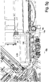
- the Figures 5 a - n show different operating states of the cutting machine in a slightly perspective view with a vertical longitudinal section along the line B - B of FIG Figure 1 d.
- the cut is in the line of sight of the Figure 1 b in the front processing lane, so for example the feed conveyor 14 a, but near its rear end in this viewing direction.
- Figure 5 With regard to the shaped tube 2, a reveals the axial area of the front shaped tube 2.1 and of the rear shaped tube 2.2 , over the common length of which the transverse ram 2.1 + 2. a goes through and which is acted upon by several piston rods 12.1 ', 12.2' in the second transverse direction 11.2 .
- One of the piston rods 12.1 ' is located in the area of the front molded tube 2.1.
- the slices cut off by the knife 3 at the front end of the shaped tube 2 fall onto a weighing station 18 which transfers the slices - or portions - to a first discharge conveyor 22 after they have been weighed.
- the weighing station 18 is according to FIG Figure 1 b not connected to the frame of the rest of the cutting machine, but rests itself on the ground in order to minimize the transmission of vibrations from the cutting machine to the weighing station 18 .
- Figure 5 a shows together with the enlarged section in Figure 5 b
- the beginning of the slicing process (described below only for the shaped tube 2 shown in section and the corresponding processing track, parallel to this, the same process can take place on the processing track behind, with the knife 3 always cutting a slice from both shaped tubes at the same time ), in which the meat strand 100 is pressed forwards by the longitudinal press ram 4 as far as the front end of the shaped tube 2 and into contact with the stop plate 13.
- the knife 3 is still completely above the two shaped tubes 2 lying next to one another .
- Figure 5 b is the distance 9 to recognize between the front end of the forming tube 2 and the stopper plate 13, which covers the free internal cross-section the shape of pipes, which simultaneously 9, the distance between the cutting edge of the knife 3 and the cutting plate 13 - represents - again in the axial direction .
- the blade 3 After descent of the blade 3, the blade 3 covers the free inner cross-section of the two - Shape tubes 2, and the separated discs - of which in Figure 5 c only the disc 101 separated from the rear processing lane can be seen - fall onto the first discharge conveyor 22 and can be transported away and further processed, as in FIG Figure 5 c shown in a state a few slices later. Thereafter, the longitudinal ram 4 pushes the cord 100 further forward again until it rests against the stop plate 13 for the cutting of the next pane
- Figure 5 d shows the state when the strand of meat 100 has been cut open to such an extent that it is only located in the axial area of the front forming tube 2.1 and the longitudinal press ram 4 is also already located in the forming tube 2.1 .
- the transverse compression walls 2.2 b 2 are relative to the central wall of the angle part 2.2 b 1 (see Figure 3 a ) moved to the outside, so that the in Figure 5 f on the feed conveyors 14 a, b brought up meat strands 100 in the direction of passage 10 b can be moved up to just before the rear end of the rear U-parts 2.2 b and in this direction by means of the Inserter 21 with its two prongs engaging the rear ends of the meat strands 100 can be inserted into the rear U-parts 2.2 b of the two shaped tube 2 , as in FIG Figure 5 g shown.
- the longitudinal pressing can be performed by moving the longitudinal ram 4 forward in the longitudinal pressing direction 10 a and then cutting - as described above - are started with the new strand of meat 100 .
- a second embodiment of the cutting machine 1 compared to the Figures 1 - 5 show the Figures 6 a , b with the two adjacent - this design can also process two strands of meat 100 simultaneously on two adjacent tracks - forming tubes 2 in Figure 6 a in loading position and in Figure 6 b in the slicing position.
- This second design differs from that of the as follows Figure 1 to 5 : On the one hand, to bring the rear U-parts 2.2 b closer together and spacing them apart from the rear transverse press rams 2.2 a or the transverse press rams 2.1 + 2, which extend over the entire axial length of the shaped tubes . a these - viewed in the first transverse direction 11.1 - moved apart or against each other, with the two parts maintaining their parallel position to each other by - again with the help of a scissor linkage 19 - the rear U-part 2.2 b while maintaining the parallel position to the rest of the Shaped tube 2 is objected to by this, so not by pivoting about a pivot axis.
- each rear U-part 2.2 b also runs in the in Figure 6 a, the loading position shown is inclined forward downward with the result that a strand of meat 100 which is transported to the rear end by means of the feed conveyor 14 a, b and finally protrudes beyond the front end of the feed conveyor 14 a, b is tipped into the U-part 2.2 b slides in and down in this, so that a separate slide can be dispensed with.
- the feeder 14 has a, b the meat strands 100 to the height of the rear end of the inclined situated in the loading position the rear U-part 2.2 bringing b and can for ease of falling in at its front end not only horizontally, but also slightly downwards be trained.
- the Figures 7 a to 7 c 1 show a second design of a cutting unit 27, the basic sequence of movements of which in the Figures 8 a , b is explained.
- this cutting unit 27 has a bar-shaped knife 3, the bar-shaped cross section being so thin that it would be better to speak of a strip-shaped knife 3 .
- the cutting unit 27 is composed of a base body 32, which is method of separating a slice in the first knife-cross direction of 31.1 as far down that a meat strand 100 passes fully through, in this case straight cutting edge 3a of the fixed therein blade 3 the cross-section, as in Figure 7 c 1 indicated.
- the base body 32 consists of two spaced-apart side supports 32 a, which are rounded by two spacer bars 32 b which are spaced parallel to each other and transverse to the direction of the side supports 32 a extending in the first transverse direction of the knife 31.1 Have cross-section, can be supplemented to form a frame-shaped base body 32 .
- the knife unit 33 in which the knife 3 is located, is attached to the lower of the two spacer rods 32 b:
- the knife unit 33 comprises three support struts 35 which are spaced apart in the longitudinal direction of the lower spacer rod 32 b and which are attached to this spacer rod 32 b Are pivotably mounted and are firmly connected at their free end to a support plate 34 extending over all three support struts 35 .
- the support plate 34 thus extends in the same direction as the spacer rod 32 b, that is, in the second knife transverse direction 31.2.
- the strip-shaped knife 3 is arranged in the feed direction 10 a immediately behind the back of the support plate 34 so that it protrudes with its cutting edge 3 a arranged on the lower edge of the knife 3 over the support edge 34 a of the support plate 34 , but relative to this approximately in the second knife transverse direction 31.2, the direction of the knife edge 3 a, is movable.
- the knife 3 is also beveled on its front surface to form a cutting edge 3 a, this bevel of the front surface of the knife 3 defining the knife plane 3 ′′ , which, as I said, under certain circumstances, against the feed direction 10 a, is somewhat in the direction of the shaped tube Front surface of the support plate 34 can be.
- the knife 3 is fastened with each of its ends to the free end of a drive lever 36 , which is designed as a two-armed drive lever and in its central area to one of the two in the main direction of extension of the cutter insert 34, the second knife Transverse direction 31.2, opposite ends of the support plate 34 are pivotable about a lever axis 36 ' extending transversely to the knife plane 3 " and thus also to the support plate plane 34' .
- the two other free ends of the drive levers 36 are connected to one another via a coupling rod 37 , so that the oscillating back and forth movement of the one driven pivot lever 36 brought about by a knife motor 38 not only via the knife 3 itself, but also via the coupling rod 37 is transferred to the other pivot lever 36 , and thereby the knife 3 can be made less stable.
- pivot levers 36 could also be designed as one-armed levers, and then the point of application of the pivot lever between the pivot axis 36 ' and the attachment point of the blade 3, which is driven by the knife motor 38 and is in operative connection with the driven pivot lever 36 would have to attack this pivot lever 36 .
- the knife 3 and also its cutting edge 3 a does not perform an exactly linear oscillating movement in the direction of its straight cutting edge 34 a, but a slightly curved movement whose radius of curvature corresponds to the distance between the lever axis 36' and the Attachment end of the knife 3 corresponds to each of the pivot levers 36 .
- an oscillating back and forth movement is referred to in a simplified manner.
- the entire knife unit 33 - consisting of support struts 35, support plate 34, knife 3, drive levers 36 - around the lower, round cross-section, serving as pivot axis 28 ' Rod 32 b can be pivoted back and forth, namely from a cutting position into a lifting position.
- Figure 7c1 the cutting position is shown in which the knife plane 3 ′′ lies parallel to the first transverse knife direction 31.1, in which the base body 32 is moved along the frame of the machine to cut the slices.
- c 2 shows the lift-off position in which the knife unit 33 is somewhat pivotable about the pivot axis 28 ', that is to say about the lower spacer rod 32 b, in the feed direction 10 a, that is, away from the meat strand.
- the Figures 7 d 1 and 7 d 2 show a design that differs from that of the Figures 7 c 1 , 2 differs only slightly.
- the motor 38 is not arranged protruding forward on the base body 27 , but runs parallel to the frame-shaped base body 27 on its side.
- Figure 8 a shows the state in which, when cutting a slice by means of the cutting movement 28 a in the first knife transverse direction 31.1 and the superimposed back and forth movement of the cutting edge 3 a in the second knife transverse direction 31.2, the knife 3 - which moves with respect to the Cutting unit 27 in the cutting position according to Figure 7 c 1 is - the disc 101 has just completely separated.
- the Figure 8 b shows the state in which, after a slice 101 has been completely cut off, the measuring unit 33 with the knife 3 has been pivoted into the lift-off position, thereby pushing the cut-off slice 101 away from the meat strand 100 and thereby facilitating throwing it onto the weighing station 18 , but above all immediately, even before the return movement 28 c has started in the first knife-transverse direction 31.1 , the forward push of the meat strand 100 already enables, which is also the goal of the knife movements 28 a to d in the Figures 4 a to c was.
- the pivoting movement naturally executes the entire cutting unit 33 except for the cutting edge 3 a , but the lifting off the end face of the meat strand 100 is correspondingly less than that of the cutting edge 3 a corresponding to the smaller distance to the pivot axis 28 '.
- This design of the cutting unit 33 thus achieves the same advantages with regard to the early advance of the meat strand 100 for cutting off the new disc 101 , but avoids the disadvantage of the solution of a rotating circular disc-shaped or sickle-shaped knife 3 , which consists in the fact that such a knife 3 - when extending over two or even more adjacent meat strands 100 and cutting them at the same time - the very large mass of such a knife is avoided, which must be accelerated and decelerated again with each cutting process.
Landscapes
- Engineering & Computer Science (AREA)
- Life Sciences & Earth Sciences (AREA)
- Forests & Forestry (AREA)
- Mechanical Engineering (AREA)
- Zoology (AREA)
- Food Science & Technology (AREA)
- Wood Science & Technology (AREA)
- Meat, Egg Or Seafood Products (AREA)
- Processing Of Meat And Fish (AREA)
- Sawing (AREA)
- Formation And Processing Of Food Products (AREA)
- Confectionery (AREA)
- Extrusion Moulding Of Plastics Or The Like (AREA)
Claims (20)
- Machine de coupe (1) pour la production de tranches (101, 102) à partir de cordons (100) d'un matériau élastique, par exemple de cordons de viande (100), et en particulier de portions (110) composées de plusieurs tranches, notamment avec un poids précis,
dans laquelle la machine de coupe (1)- comprend une pluralité de tubes de façonnage (2) pour un cordon de viande (100) chacun, qui sont disposés parallèlement les uns à côté des autres, ouverts à l'avant et à l'arrière et s'étendent dans la direction de pressage longitudinale (10a), la direction axiale,- comprend un poinçon de pressage longitudinal (4) pour chacun des tubes de façonnage (2), qui peut être introduit dans le tube de façonnage (2) à partir de l'extrémité de chargement arrière (2b) dans la direction de pressage longitudinale (10a) du tube de façonnage (2),- à l'extrémité avant de coupe (2a) des tubes de façonnage (2), un couteau (3) pour séparer les tranches (101, 102) des cordons (100) est disposé de manière mobile dans une première direction transversale de couteau (31.1),- dans lequel les tubes de façonnage (2) sont constitués, dans la direction circonférentielle, d'une pluralité de pièces de façonnage mobiles les unes par rapport aux autres dans au moins l'une de deux directions transversales (11.1, 11.2) et présentent ainsi une section transversale réglable dans au moins l'une des deux directions transversales (11.1, 11.2) par rapport à la direction longitudinale (10),caractérisé en ce que- il y a plusieurs plaques de butée (13), en particulier une plaque de butée (13) par tube de façonnage, s'étendant parallèlement au plan du couteau (3"), mobile dans une direction transversale (11.1, 11.2), en particulier mobile dans la première direction transversale du couteau (31.1). - Machine de coupe selon la revendication 1,
caractérisé en ce que- le couteau (3) est mobile dans la première direction transversale du couteau (31.1) et en particulier dans la direction axiale (10a), la direction d'avance, vers les tubes de façonnage (2) au moyen d'une unité de coupe (27), commandée par une commande (20),et/ou- la plaque de butée (13) est fermement reliée au couteau (3) dans la direction transversale du couteau (31.1) et fait notamment partie de l'unité de coupe (27),et/ou- le couteau (3) s'étend en largeur sur tous les tubes de façonnage (2) afin de pouvoir découper des tranches (101, 102) de tous les tubes de façonnage (2) adjacents en une seule opération,et/ou- le couteau (3) est un couteau (3) oscillant, en particulier dans la direction (3'a) dans laquelle s'étend son arête de couteau (3a), notamment sous la forme d'une poutre ou d'une bande, ou est un couteau rotatif (3), notamment un couteau (3)sous la forme d'un disque circulaire. - Machine de coupe selon l'une des revendications précédentes,
caractérisé en ce que- vu dans la direction de pressage longitudinale (10a), le couteau (3) et la plaque de butée (13) ne se chevauchent pas, de préférence dans le plan transversal, c'est-à-dire radialement par rapport à la direction de pressage longitudinale (10a), il n'y a qu'un étroit espace de moins de 20 mm, en particulier moins de 10 mm, entre eux. - Machine de coupe selon l'une des revendications précédentes,
caractérisé en ce que- la section libre intérieure (7') des tubes de façonnage (2) présente chacun deux côtés opposés s'étendant parallèlement l'un à l'autre et est notamment de forme rectangulaire ou en parallélogramme,et/ou- les poinçons de pressage longitudinaux (4) pour les différents tubes façonnés (2) peuvent être commandés indépendamment les uns des autres dans leur avance axiale et disposent notamment d'un capteur pour détecter la position axiale du poinçon de pressage longitudinal (4). - Machine de coupe selon l'une des revendications précédentes,
caractérisé en ce que- les tubes de façonnage (2) à l'état fermé sur la circonférence sont inclinés obliquement vers le bas dans la direction de pressage longitudinale (10a) vers leur extrémité de coupe avant (2a), en particulier d'un angle (15) compris entre 20° et 70°, mieux entre 30° et 60°, mieux entre 40° et 50°, par rapport à l'horizontale,et/ou- sur le côté du couteau (3) opposé au tube de façonnage (2) est disposée une plaque de butée (13), en particulier perpendiculairement à la direction longitudinale de pressage (10a), la distance axiale (9) entre le couteau (3) et le tube de façonnage étant réglable. - Machine de coupe selon l'une des revendications précédentes,
caractérisé en ce que
chaque tube de façonnage (2) est subdivisé, au moins par rapport à une pièce de façonnage, dans la direction de pressage longitudinale (10a), en un tube de façonnage avant (2.1) et un tube de façonnage arrière (2.2), en particulier directement adjacent à celui-ci, qui sont mobiles l'un par rapport à l'autre transversalement à la direction de pressage (10a) entre une position alignée et une position non alignée, le tube de façonnage avant (2a) présentant de préférence une longueur comprise entre 2 % et 50 %, mieux entre 5 % et 30 %, mieux entre 10 % et 20 % de la longueur totale du tube de façonnage (2). - Machine de coupe selon la revendication 6,
caractérisé en ce que
entre le tube de façonnage avant (2.1) et le tube de façonnage arrière (2.2), en particulier séparément pour chaque tube de façonnage (2), il existe une plaque intermédiaire (8) qui peut être déplacée dans la direction transversale (11) à la direction de pressage longitudinale (10a) entre une position fermée, dans laquelle elle ferme la section transversale intérieure libre (7') du tube de façonnage (2), et une position ouverte, dans laquelle elle laisse ce dernier ouvert, de manière contrôlée, en particulier séparément, et est fixée en particulier au tube de façonnage arrière (2.2). - Machine à couper selon les revendications 6 ou 7,
caractérisé en ce que- chaque tube de façonnage arrière (2.2), vu dans la direction longitudinale (10), est constitué d'au moins deux parties de façonnage arrières (2.2a, b) qui peuvent être déplacées l'une par rapport à l'autre au moins dans la deuxième direction transversale (11.2) à la direction longitudinale (10)et en ce que- les deux parties de façonnage arrières (2.2a, b) du tube de façonnage arrière (2.2) sont complètement désengagées dans la deuxième direction transversale (11.2) et peuvent être amenées à distance l'une de l'autre. - Machine de coupe selon la revendication 8,
caractérisé en ce que- au moins la partie de façonnage arrière (2.2b) comprenant la paroi inférieure de l'espace libre intérieur (7) du tube de façonnage arrière (2.2) peut être abaissée, en particulier rabattue, dans une position de chargement, en particulier horizontale, dans laquelle elle est alignée, en particulier, avec un convoyeur d'alimentation (14a, b) pour des cordons (100)et/ou- la plaque intermédiaire (8) est fixée à la pièce de façonnage arrière (2.2b) comprenant la paroi inférieure de l'espace libre intérieur (7) du tube de façonnage arrière (2.2). - Machine de coupe selon l'une des revendications 6 à 9,
caractérisé en ce que- le tube de façonnage arrière (2.2) est constitué, en particulier, uniquement de deux parties de façonnage arrière (2.2a, b) et, vu dans la direction de pressage longitudinale (10a), une partie de façonnage arrière (2.2b) de chaque tube de façonnage arrière (2.2) est formée comme une partie en U (2.2b) et l'autre partie de façonnage arrière (2. 2a) est conçu comme un poinçon de pressage transversal (2.2a) qui est mobile à cet effet et qui, dans la deuxième direction transversale (11.2), s'adapte étroitement au côté circonférentiel ouvert de la partie en U (2.2b) et peut être déplacé dans cette dernière, et en particulier- en amont de la partie en U (2.2b) abaissée en position de chargement, une auge de compression transversale (16) ouverte à l'avant et à l'arrière et en haut dans le sens longitudinal (10b) est montée comme autre pièce de tube de façonnage, en particulier directement devant, dans laquelle les deux parois latérales opposées de l'auge de compression transversale (16) peuvent être déplacées l'une par rapport à l'autre dans la première direction transversale (11:1). - Machine de coupe selon la revendication 10,
caractérisé en ce que
une paroi latérale de l'auge de compression transversale (16) est fermement reliée au fond de l'auge de compression transversale (16), et- soit le fond est formé par une bande d'alimentation (6) pour les cordons (100) qui est mobile dans le sens longitudinal (10b) de l'auge de pressage transversale (16)- soit il existe un poussoir (21) qui peut être déplacé dans la direction longitudinale (10b) et qui peut être introduit dans l'espace libre intérieur de l'auge de compression transversale (16) et/ou de la partie en U (2.2b), et il existe en particulier un capteur de position pour déterminer la position longitudinale du poussoir (21). - Procédé de fabrication de tranches (101, 102) et en particulier de portions (110) composées de plusieurs tranches, notamment avec un poids précis, à partir d'un cordon (100) d'un matériau élastique, par exemple un cordon de viande (100), où- le cordon (100) est disposé dans un tube de façonnage (2),- le cordon (100) est pressé dans le tube de façonnage (2) dans au moins une direction transversale (11.1, 11.2) et dans la direction de pressage longitudinale (10a) du tube de façonnage (2),- plusieurs cordons (100) sont disposés en parallèle dans une première direction transversale (11.1) les uns à côté des autres sur plusieurs pistes de traitement, en particulier simultanément, dans un tube de façonnage (2) chacun et sont traités,- le cordon (100) est poussé vers l'avant dans la direction de pressage longitudinale (10a) au-delà de l'extrémité de coupe avant (2a) du tube de façonnage (2),- en avant de l'extrémité de coupe avant (2a) du tube de façonnage (2), une tranche (101) est séparé de chaque cordon (100) au moyen d'au moins un couteau (3),caractérisé en ce que- ledit au moins un couteau (3) du dispositif de coupe (27) est déplacé dans une direction transversale (11) à la direction de pressage longitudinale (10a) afin de séparer les tranches (101),- la poussée vers l'avant dans la direction de pressage longitudinale (10a) du cordon (100) au-delà de l'extrémité de coupe avant (2a) du tube de façonnage (2) pour le découpage en tranches (100) a lieu jusqu'à l'une de plusieurs butées, en particulier des plaques de butée (13), qui sont mobiles de manière contrôlée dans au moins une direction transversale (11),- le mouvement des différentes butées, en particulier des plaques de butée (13) couvrant la section d'un seul tube de façonnage à la fois, peut être contrôlé et en particulier sont contrôlées indépendamment les unes des autres.
- Procédé selon la revendication 12,
caractérisé en ce que- la vitesse du mouvement transversal du couteau (3) est contrôlée par rapport au diamètre et à la vitesse de rotation du couteau (3),et/ou- pour le pressage dans la direction transversale, ces cordons (100) sont chacun pressés transversalement dans la première direction transversale (11.1) dans le tube de façonnage respectif (2) ou en amont de celui-ci avant le pressage longitudinal, et- ces cordons (100) sont pressés transversalement dans le tube de façonnage (2) avant le pressage longitudinal, de préférence après le pressage transversal dans la première direction transversale (11.1), dans chaque cas dans une deuxième direction transversale (11.2) qui est en particulier perpendiculaire à la première direction transversale (11.1). - Procédé selon l'une des revendications précédentes,
caractérisé en ce que- après chaque découpe, le couteau (3) est déplacé axialement dans le sens de la pression longitudinale (10a), et pendant ce temps, le cordon de viande (100) est déjà avancé au-delà de l'extrémité avant du tube de façonnage (2),- en particulier immédiatement après la découpe d'au moins une tranche (101, 102), le couteau (3) est déplacé vers l'avant dans le sens de l'avancement (10a) d'une quantité égale à l'épaisseur d'une tranche (101), avant ou simultanément au retour du couteau (3) dans le sens transversal à sa position de départ. - Procédé selon l'une des revendications de procédé précédentes,
caractérisé en ce que- la plaque de butée (13) et le couteau (3) peuvent être réglés l'un par rapport à l'autre dans le sens longitudinal à une distance correspondant à l'épaisseur souhaitée de la tranche, en particulier séparément pour chaque tube de façonnage (2), et- en particulier la plaque de butée (13) et le couteau (3) en tant qu'unité de coupe (27) sont déplacés ensemble au moins dans la direction de coupe (27). - Procédé selon l'une des revendications de procédé précédentes,
caractérisé en ce que- chaque tube de façonnage (2) est réalisé en deux parties dans sa direction longitudinale (10) avec un tube de façonnage avant (2.1) et un tube de façonnage arrière (2.2), la compression transversale du cordon (100) dans le tube de façonnage avant (2.1) étant commandée indépendamment de la compression transversale dans le tube de façonnage arrière suivant (2.2), et- en particulier le tube de façonnage avant (2.1) et le tube de façonnage arrière (2.2) du même tube de façonnage (2) sont ajustés à la même section transversale libre intérieure (7'), alignée, à l'état pressé. - Procédé selon la revendication 16,
caractérisé en ce que
dès que l'extrémité arrière d'un ou, en particulier, de tous les cordons insérés (100) se trouve uniquement dans la zone axiale du tube de façonnage avant respectif (2.1), en particulier l'un après l'autre, dans le tube de façonnage (2) concerné ou dans tous les tubes de façonnage (2)- le reste du cordon (100) dans le tube de façonnage avant (2.1) est déplacé plus loin dans la direction d'alimentation (10a), en particulier à l'aide du poinçon de pressage longitudinal (4), et est complètement découpé,- simultanément on commence au moins à charger le tube de façonnage arrière (2.2) avec un nouveau cordon (100) à couper, en particulier en abaissant la partie inférieure de façonnage arrière (2.2b) du tube de façonnage arrière (2.2) au moins à son extrémité de chargement (2b), en particulier sur toute sa longueur axiale, vers le bas dans une position de chargement, en particulier une position de chargement horizontale, alignée avec le convoyeur d'alimentation (14a, b) pour les nouveaux cordons (100), et- le cordon suivant (100) est inséré dans la partie inférieure arrière (2.2b) du tube de façonnage arrière (2.2), en particulier sous la tige de poinçon (12) du poinçon de pressage longitudinal (4), et en particulier transporté vers l'avant, de préférence jusqu'à l'extrémité avant de la partie de façonnage arrière (2.2b) du tube de façonnage arrière, en particulier jusqu'à la plaque intermédiaire (8) qui s'y trouve- dès que le cordon (100) est coupé, le poinçon de pressage longitudinal (4) est rétracté. - Procédé selon l'une des revendications 16 ou 17,
caractérisé en ce que- avant ou après l'insertion du nouveau cordon (100) dans la partie de façonnage arrière inférieure (2.2b), le nouveau cordon (100) est compressé transversalement dans la première direction transversale (11.1) en particulier- la partie de façonnage arrière inférieure (2.2b) du tube de façonnage arrière (2.2) est de nouveau soulevée dans une position de pressage en alignement avec la partie inférieure avant (2.1b), de sorte que le cordon (100) se trouve devant le poinçon de pressage longitudinal (4), et le tube de façonnage arrière (2.2) est ainsi refermé, en particulier sur la circonférence, et le cordon (100) qui s'y trouve est compressé transversalement dans la deuxième direction transversale (11.2) au moyen d'un poinçon de pressage transversal (2.2b1),
ou- le poinçon de pressage longitudinal (4) est rétracté au moins jusqu'à l'extrémité arrière du nouveau cordon (100) inséré dans la partie de façonnage arrière (2.2b). - Procédé selon l'une des revendications 16 à 18,
caractérisé en ce que- soit une paroi de pressage transversale (2.2b2) éventuellement présente sur la partie de façonnage arrière inférieur (2.2b) est déplacée radialement vers l'extérieur par rapport au reste de la partie de façonnage arrière inférieur (2.2b) avant l'insertion du nouveau cordon (100) et avant que la partie de façonnage arrière inférieur (2.2b) ne soit soulevée est rapprochée de la largeur prédéterminée dans la position de pressage et le nouveau cordon (100) est pressé transversalement,- soit le nouveau cordon (100) est pressé transversalement dans la première direction transversale (11. 1) dans un poste de pressage transversal disposé entre la partie de façonnage arrière inférieur (2.2b) et le convoyeur d'alimentation (14). - Procédé selon l'une des revendications 16 à 19,
caractérisé en ce que
en position de chargement, le cordon suivant (100) dans la direction longitudinale (10b) du convoyeur d'alimentation (14) dans la partie de façonnage arrière, en particulier en forme de U, du tube de façonnage arrière (2.2b)- est soit poussé par un poussoir (21) déplaçable en direction du convoyeur d'alimentation (14) et détermine ainsi en particulier la longueur du cordon de viande (100), notamment en déterminant la position du poussoir (21) dans sa position la plus avancée,- soit le cordon suivant (100) est transporté dans la partie de façonnage arrière (2.2b) reposant sur une ceinture de tube de façonnage (6) mobile dans la direction longitudinale (10), qui est notamment un composant de cette partie de façonnage arrière (2.2b).
Applications Claiming Priority (2)
| Application Number | Priority Date | Filing Date | Title |
|---|---|---|---|
| DE102016107849.2A DE102016107849A1 (de) | 2016-04-28 | 2016-04-28 | Schneidemaschine sowie Verfahren zum Aufschneiden von elastischen Strängen, insbesondere Fleischsträngen |
| PCT/EP2017/060012 WO2017186827A1 (fr) | 2016-04-28 | 2017-04-27 | Machine de coupe et procédé pour découper des boudins de matière élastiques, notamment des boudins de viande |
Publications (2)
| Publication Number | Publication Date |
|---|---|
| EP3448643A1 EP3448643A1 (fr) | 2019-03-06 |
| EP3448643B1 true EP3448643B1 (fr) | 2020-09-30 |
Family
ID=58633000
Family Applications (4)
| Application Number | Title | Priority Date | Filing Date |
|---|---|---|---|
| EP17168340.2A Active EP3238898B1 (fr) | 2016-04-28 | 2017-04-27 | Machine de coupe et procédé de coupe de cordons élastiques, en particulier des cordons de viande |
| EP17719602.9A Active EP3448641B1 (fr) | 2016-04-28 | 2017-04-27 | Trancheuse et procédé pour trancher des boudins élastiques, en particulier des boudins de viande |
| EP17719604.5A Active EP3448642B1 (fr) | 2016-04-28 | 2017-04-27 | Machine de découpe ainsi que procédé pour découper des blocs élastiques, en particulier des blocs de viande |
| EP17723297.2A Active EP3448643B1 (fr) | 2016-04-28 | 2017-04-27 | Machine de coupe et procédé pour découper des boudins de matière élastiques, notamment des boudins de viande |
Family Applications Before (3)
| Application Number | Title | Priority Date | Filing Date |
|---|---|---|---|
| EP17168340.2A Active EP3238898B1 (fr) | 2016-04-28 | 2017-04-27 | Machine de coupe et procédé de coupe de cordons élastiques, en particulier des cordons de viande |
| EP17719602.9A Active EP3448641B1 (fr) | 2016-04-28 | 2017-04-27 | Trancheuse et procédé pour trancher des boudins élastiques, en particulier des boudins de viande |
| EP17719604.5A Active EP3448642B1 (fr) | 2016-04-28 | 2017-04-27 | Machine de découpe ainsi que procédé pour découper des blocs élastiques, en particulier des blocs de viande |
Country Status (9)
| Country | Link |
|---|---|
| US (4) | US10875207B2 (fr) |
| EP (4) | EP3238898B1 (fr) |
| CN (4) | CN209579743U (fr) |
| BR (1) | BR102017008872B1 (fr) |
| DE (1) | DE102016107849A1 (fr) |
| DK (1) | DK3448641T3 (fr) |
| ES (4) | ES2760463T3 (fr) |
| PL (1) | PL3238898T3 (fr) |
| WO (3) | WO2017186828A1 (fr) |
Cited By (1)
| Publication number | Priority date | Publication date | Assignee | Title |
|---|---|---|---|---|
| US12311567B2 (en) | 2021-10-25 | 2025-05-27 | Provisur Technologies, Inc. | Releasable side strapping assembly for a food product slicing apparatus |
Families Citing this family (35)
| Publication number | Priority date | Publication date | Assignee | Title |
|---|---|---|---|---|
| DE102016101753A1 (de) * | 2016-02-01 | 2017-08-03 | Textor Maschinenbau GmbH | Aufschneiden von lebensmittelprodukten |
| DE102016107849A1 (de) | 2016-04-28 | 2017-11-02 | Tvi Entwicklung Und Produktion Gmbh | Schneidemaschine sowie Verfahren zum Aufschneiden von elastischen Strängen, insbesondere Fleischsträngen |
| WO2018091993A1 (fr) * | 2016-11-17 | 2018-05-24 | Milan Conception Inc. | Procédé et appareil de coupe destinés à couper des profils d'ébauche |
| IT201600126477A1 (it) * | 2016-12-14 | 2018-06-14 | Turatti Srl | Macchine per formare spaghetti di prodotti vegetali |
| DE102017112178A1 (de) * | 2017-06-02 | 2018-12-06 | Tvi Entwicklung Und Produktion Gmbh | Schneidvorrichtung sowie Schneidverfahren |
| DE102017112177B4 (de) * | 2017-06-02 | 2023-11-23 | Tvi Entwicklung Und Produktion Gmbh | Schneideinheit sowie Schneidverfahren |
| WO2019147784A1 (fr) * | 2018-01-26 | 2019-08-01 | Provisur Technologies, Inc. | Appareil de tranchage de boudins de produit alimentaire destiné à trancher de multiples couches de boudins de produit alimentaire empilés |
| DE102018106300B4 (de) * | 2018-03-19 | 2024-03-14 | Tvi Entwicklung Und Produktion Gmbh | Verfahren zum Verpressen und Aufschneiden von elastischen Laiben sowie Schneidemaschine hierfür |
| CN109090196B (zh) * | 2018-07-23 | 2020-11-17 | 山东名邦食品股份有限公司 | 一种便于固定的鳗鱼罐头加工用鳗鱼切片辅助装置 |
| US10653154B2 (en) * | 2018-10-08 | 2020-05-19 | Kronos Foods Corp. | Horizontal char slicer, system and method |
| KR102222315B1 (ko) * | 2018-12-13 | 2021-03-03 | 이근영 | 냉장육 정량 육절기 |
| JP7220789B2 (ja) * | 2018-12-13 | 2023-02-10 | グムヨン イ | 冷蔵肉定量肉切機 |
| US11498138B2 (en) * | 2019-01-23 | 2022-11-15 | Steve Dunivan | Bandsaw automated portioning saw system and method of use |
| WO2020171880A1 (fr) | 2019-02-19 | 2020-08-27 | Provisur Technologies, Inc. | Appareil transporteur à trancher et à présentation multiple |
| DE102019110026A1 (de) * | 2019-04-16 | 2020-10-22 | Tvi Entwicklung Und Produktion Gmbh | Schneidemaschine sowie Verfahren zum Aufschneiden eines Laibes in Scheiben |
| GB2586438B (en) * | 2019-05-03 | 2022-08-31 | Thurne Middleby Ltd | Feeding of food products in slicing or portioning machines |
| DE102019133068A1 (de) * | 2019-12-04 | 2021-06-10 | Tvi Entwicklung Und Produktion Gmbh | Verfahren zum Verpressen und ggfs. Aufschneiden eines Laibes sowie hierfür geeignete Aufschneidemaschine |
| DE102019135165B4 (de) * | 2019-12-19 | 2025-11-13 | Tvi Entwicklung Und Produktion Gmbh | Schneideinheit und Aufschneide-Maschine mit einer solchen Schneideinheit |
| DE102020112864A1 (de) * | 2020-05-12 | 2021-11-18 | Tvi Entwicklung Und Produktion Gmbh | Gewichts-Variations-Verfahren sowie Aufschneidemaschine für dessen Durchführung |
| DE102020112863A1 (de) | 2020-05-12 | 2021-11-18 | Tvi Entwicklung Und Produktion Gmbh | Gewichts-Variations-Verfahren sowie Aufschneidemaschine zu seinem Betrieb |
| FR3114038B1 (fr) * | 2020-09-11 | 2022-11-11 | Soc Dingenierie Limousine Dapplication Technique | Système de dosage destiné à réaliser des portions d’un matériau malléable |
| CN112544670B (zh) * | 2020-11-27 | 2022-04-26 | 杭州小帘栊餐饮管理有限公司 | 一种肉骨称量切割装置 |
| DE102020134505B3 (de) * | 2020-12-21 | 2022-03-10 | Tvi Entwicklung Und Produktion Gmbh | Verfahren zum Verpressen und Aufschneiden eines Produkt-Stückes sowie Aufschneidemaschine hierfür |
| CN114683339B (zh) * | 2020-12-31 | 2024-11-05 | 江苏万阳电子有限公司 | 一种伺服送管系统 |
| DE102021103850A1 (de) | 2021-02-18 | 2022-08-18 | Tvi Entwicklung Und Produktion Gmbh | Mehrspurige Aufschneide-Maschine mit jeweils einer Anschlagplatte pro Spur sowie Verfahren zu deren Betrieb |
| DE102021103849A1 (de) * | 2021-02-18 | 2022-08-18 | Tvi Entwicklung Und Produktion Gmbh | Aufschneide-Maschine sowie Betriebs-Verfahren hierfür zum Verbessern des ziehenden Schnittes |
| CN113287651B (zh) * | 2021-04-28 | 2022-11-25 | 山东源泉食品有限公司 | 一种用于冻肉刨片机上的配重进给机构 |
| KR102386845B1 (ko) * | 2022-01-25 | 2022-04-15 | 박기남 | 햄버거 패티용 고기를 가공하는 장치 및 그 방법 |
| GB2617592A (en) * | 2022-04-13 | 2023-10-18 | Thurne Middleby Ltd | Food portioning machine and methods of operation thereof |
| DE102022109293A1 (de) * | 2022-04-14 | 2023-10-19 | Tvi Entwicklung Und Produktion Gmbh | Aufschneide-Maschine mit Quer-Transfervorrichtung zum Beladen außerhalb der Maschine sowie Belade-Verfahren für eine Aufschneide-Maschine |
| DE102023108709A1 (de) * | 2023-04-05 | 2024-10-10 | Multivac Sepp Haggenmüller Se & Co. Kg | Aufschneide-Maschine mit Parkposition für Greifer |
| BE1031835B1 (nl) * | 2023-07-27 | 2025-02-26 | Marelec Food Tech | Scheidingsinrichting voor portioneermachine |
| DE102024107416A1 (de) * | 2024-03-15 | 2025-09-18 | Tvi Entwicklung Und Produktion Gmbh | Aufschneidemaschine |
| DE102024107417B4 (de) * | 2024-03-15 | 2026-02-05 | Tvi Entwicklung Und Produktion Gmbh | Aufschneidemaschine |
| CN119658705B (zh) * | 2025-02-19 | 2025-06-20 | 河南科技学院 | 一种用于尾叉骨剔骨的主从式双臂力位混合控制方法 |
Family Cites Families (42)
| Publication number | Priority date | Publication date | Assignee | Title |
|---|---|---|---|---|
| US2241807A (en) * | 1940-05-23 | 1941-05-13 | Logansport Machine Inc | Hydraulic press system |
| US2565245A (en) * | 1949-11-12 | 1951-08-21 | Churchill Meat Company | Method and means for shaping meats |
| US3703064A (en) | 1970-03-30 | 1972-11-21 | Cubb Pac Corp | Packaging of meat |
| US3821913A (en) * | 1972-09-28 | 1974-07-02 | Chemetron Corp | Apparatus for accumulating stacks of sliced material |
| US3975795A (en) | 1975-01-20 | 1976-08-24 | Union Carbide Corporation | Product stuffing apparatus and method |
| US4193167A (en) * | 1978-11-09 | 1980-03-18 | Armour And Company | Apparatus for molding meat patties |
| DE3540904C2 (de) * | 1985-11-19 | 1995-08-10 | Holac Maschbau Gmbh | Vorrichtung zum Schneiden von Lebensmitteln, insbesondere von Fleisch |
| ES2015660A6 (es) | 1989-05-19 | 1990-09-01 | Metalquimia Sa | Procedimiento para dosificacion y embutido de masas carnicas, al vacio y maquina para su realizacion. |
| US5112634A (en) * | 1991-07-31 | 1992-05-12 | Swearingen Ralph M | Method and apparatus for making ground meat patties |
| US5342236A (en) * | 1993-05-12 | 1994-08-30 | Milton Industries, Inc. | Meat cutter |
| IT1269115B (it) * | 1994-06-16 | 1997-03-21 | Perini Fabio Spa | Dispositivo per il cambio automatico di bobine di materiale nastriforme |
| JP2787907B2 (ja) * | 1995-12-15 | 1998-08-20 | 日本電気株式会社 | 半導体装置用樹脂封止金型 |
| US20020104414A1 (en) * | 1997-08-15 | 2002-08-08 | Joachim Schill | Method and device for slicing pieces of fresh whole-muscle meat |
| JP4127738B2 (ja) | 1999-03-31 | 2008-07-30 | プリマハム株式会社 | ハム等の食物原木スライス装置 |
| JP4204145B2 (ja) | 1999-08-16 | 2009-01-07 | ハイテック株式会社 | ソーセージ等の食品を製造する方法及び装置 |
| US7364504B2 (en) * | 2003-09-02 | 2008-04-29 | Remington Holdings Llc | Apparatus and method for producing controlled portions of meat products |
| DE10353114A1 (de) * | 2003-10-15 | 2005-05-12 | Cfs Kempten Gmbh | Verfahren und Vorrichtung zum Aufschneiden von Lebensmittelriegeln |
| DE102004041915B4 (de) * | 2004-08-30 | 2017-08-24 | Tvi Entwicklung Und Produktion Gmbh | Vorrichtungen und Verfahren zum Portionieren |
| DE102007019106B4 (de) | 2006-04-21 | 2011-08-25 | Völkl, Thomas, 83052 | Fleischfaserentfernung |
| PL2084968T3 (pl) * | 2008-02-04 | 2011-10-31 | Marel Hf | Sposób przetwarzania elementów takich jak kawałki mięsa |
| DE102008020246A1 (de) * | 2008-04-22 | 2009-11-12 | Maschinenbau Heinrich Hajek Gmbh & Co. | Verfahren zur Beladung einer Hochgeschwindigkeits-Schneidmaschine mit Produkten und Beladungseinrichtung hierfür |
| ES2385738T3 (es) | 2009-02-10 | 2012-07-31 | Albert Handtmann Maschinenfabrik Gmbh & Co. Kg | Válvula de corte y procedimiento para obtener porciones |
| DE102009038875A1 (de) * | 2009-08-26 | 2011-03-03 | Weber Maschinenbau Gmbh Breidenbach | Antriebsmotor |
| EP2516118B1 (fr) * | 2009-12-23 | 2013-11-06 | CFS Bühl GmbH | Procédé pour classer par ordre de qualité des tranches d'aliment découpées dans un pain d'aliment |
| DE102010035657B4 (de) | 2010-03-19 | 2015-01-29 | Anton & Völkl Patente Ug (Haftungsbeschränkt) & Co. Kg | Portioniermaschine |
| IT1406049B1 (it) | 2011-02-18 | 2014-02-06 | Grasselli | Macchina per il taglio della carne |
| DE102011051210A1 (de) * | 2011-06-20 | 2012-12-20 | Uwe Reifenhäuser | Verfahren und Vorrichtung zum Schneiden eines Lebensmittelstrangs in Scheiben |
| DE102011111602A1 (de) * | 2011-07-08 | 2013-01-10 | Weber Maschinenbau Gmbh Breidenbach | Lebensmittelaufschneidevorrichtung |
| DE102011112171A1 (de) * | 2011-09-01 | 2013-03-07 | Weber Maschinenbau Gmbh Breidenbach | Verfahren und Vorrichtung zum mehrspurigen Aufschneiden von Lebensmittelprodukten |
| DE102012000545A1 (de) * | 2012-01-13 | 2013-07-18 | Weber Maschinenbau Gmbh Breidenbach | Verfahren und Vorrichtung zum Erstellen von Portionen |
| DE102012102649A1 (de) * | 2012-03-27 | 2013-10-02 | Uwe Reifenhäuser | Verfahren und Vorrichtung zum gewichtsgenauen Schneiden eines Lebensmittelstranges |
| US8342919B1 (en) * | 2012-06-11 | 2013-01-01 | Mauer James E | Method and apparatus for cutting the second joint of a poultry wing and product therefrom |
| US8808070B2 (en) * | 2012-12-26 | 2014-08-19 | Chao Jing Weng | Bulk meat cutting apparatus |
| DE102013207504A1 (de) * | 2013-04-25 | 2014-10-30 | Weber Maschinenbau Gmbh Breidenbach | Vorrichtung zum Fördern von Lebensmittelprodukten |
| DE102013114664A1 (de) * | 2013-12-20 | 2015-06-25 | Weber Maschinenbau Gmbh Breidenbach | Vorrichtung und Verfahren zum Aufschneiden von Lebensmittelprodukten |
| WO2015171858A1 (fr) | 2014-05-07 | 2015-11-12 | Formax, Inc. | Appareil et procédés de tranchage de produit alimentaire |
| DE102014106353B4 (de) * | 2014-05-07 | 2025-05-22 | Multivac Sepp Haggenmüller Se & Co. Kg | Schneidmaschine zum Schneiden von Lebensmitteln |
| CN204935713U (zh) | 2015-09-10 | 2016-01-06 | 李树忠 | 一种直切式羊肉切片机 |
| US20170232628A1 (en) * | 2016-02-12 | 2017-08-17 | Globe Food Equipment Company | Product slicer |
| US20170232629A1 (en) * | 2016-02-12 | 2017-08-17 | Globe Food Equipment Company | Product slicer |
| DE102016107849A1 (de) | 2016-04-28 | 2017-11-02 | Tvi Entwicklung Und Produktion Gmbh | Schneidemaschine sowie Verfahren zum Aufschneiden von elastischen Strängen, insbesondere Fleischsträngen |
| US10259133B2 (en) * | 2016-05-23 | 2019-04-16 | Robin Thurgood | Deli slicer and packaging system |
-
2016
- 2016-04-28 DE DE102016107849.2A patent/DE102016107849A1/de not_active Ceased
-
2017
- 2017-04-27 DK DK17719602.9T patent/DK3448641T3/da active
- 2017-04-27 CN CN201790000797.2U patent/CN209579743U/zh active Active
- 2017-04-27 US US16/096,104 patent/US10875207B2/en active Active
- 2017-04-27 US US16/096,991 patent/US10492504B2/en active Active
- 2017-04-27 CN CN201790000808.7U patent/CN209078854U/zh active Active
- 2017-04-27 ES ES17168340T patent/ES2760463T3/es active Active
- 2017-04-27 EP EP17168340.2A patent/EP3238898B1/fr active Active
- 2017-04-27 CN CN201790000785.XU patent/CN209648830U/zh active Active
- 2017-04-27 EP EP17719602.9A patent/EP3448641B1/fr active Active
- 2017-04-27 PL PL17168340T patent/PL3238898T3/pl unknown
- 2017-04-27 EP EP17719604.5A patent/EP3448642B1/fr active Active
- 2017-04-27 WO PCT/EP2017/060014 patent/WO2017186828A1/fr not_active Ceased
- 2017-04-27 WO PCT/EP2017/060010 patent/WO2017186826A1/fr not_active Ceased
- 2017-04-27 ES ES17723297T patent/ES2829293T3/es active Active
- 2017-04-27 WO PCT/EP2017/060012 patent/WO2017186827A1/fr not_active Ceased
- 2017-04-27 ES ES17719604T patent/ES2835305T3/es active Active
- 2017-04-27 US US16/096,897 patent/US10843364B2/en active Active
- 2017-04-27 BR BR102017008872-3A patent/BR102017008872B1/pt active IP Right Grant
- 2017-04-27 EP EP17723297.2A patent/EP3448643B1/fr active Active
- 2017-04-27 ES ES17719602T patent/ES2929536T3/es active Active
- 2017-04-28 CN CN201710296012.7A patent/CN107379055B/zh active Active
- 2017-04-28 US US15/582,494 patent/US10245745B2/en active Active
Non-Patent Citations (1)
| Title |
|---|
| None * |
Cited By (5)
| Publication number | Priority date | Publication date | Assignee | Title |
|---|---|---|---|---|
| US12311567B2 (en) | 2021-10-25 | 2025-05-27 | Provisur Technologies, Inc. | Releasable side strapping assembly for a food product slicing apparatus |
| US12427687B2 (en) | 2021-10-25 | 2025-09-30 | Provisur Technologies, Inc. | Profile scanner and feed assembly for a high-speed food slicing apparatus |
| US12441021B2 (en) | 2021-10-25 | 2025-10-14 | Provisur Technologies, Inc. | Blade assembly and counterweight mechanism for a high-speed food slicing apparatus, and methods associated with the same |
| US12558808B2 (en) | 2021-10-25 | 2026-02-24 | Provisur Technologies, Inc. | Blade assembly and retraction mechanism for a high-speed food slicing apparatus |
| US12570021B2 (en) | 2021-10-25 | 2026-03-10 | Provisur Technologies, Inc. | Drive assembly for a food product slicing apparatus |
Also Published As
| Publication number | Publication date |
|---|---|
| US20170312931A1 (en) | 2017-11-02 |
| EP3448642A1 (fr) | 2019-03-06 |
| CN107379055B (zh) | 2020-06-05 |
| BR102017008872B1 (pt) | 2024-02-27 |
| BR102017008872A2 (pt) | 2018-06-19 |
| CN107379055A (zh) | 2017-11-24 |
| CN209579743U (zh) | 2019-11-05 |
| US10843364B2 (en) | 2020-11-24 |
| ES2829293T3 (es) | 2021-05-31 |
| ES2835305T3 (es) | 2021-06-22 |
| CN209648830U (zh) | 2019-11-19 |
| DK3448641T3 (da) | 2022-10-31 |
| EP3448642B1 (fr) | 2020-10-07 |
| EP3238898A1 (fr) | 2017-11-01 |
| ES2760463T3 (es) | 2020-05-14 |
| ES2929536T3 (es) | 2022-11-30 |
| WO2017186828A1 (fr) | 2017-11-02 |
| WO2017186826A1 (fr) | 2017-11-02 |
| US10245745B2 (en) | 2019-04-02 |
| EP3448641A1 (fr) | 2019-03-06 |
| US20190223459A1 (en) | 2019-07-25 |
| PL3238898T3 (pl) | 2020-04-30 |
| EP3238898B1 (fr) | 2019-10-16 |
| DE102016107849A1 (de) | 2017-11-02 |
| WO2017186827A1 (fr) | 2017-11-02 |
| EP3448643A1 (fr) | 2019-03-06 |
| US10875207B2 (en) | 2020-12-29 |
| US20190232516A1 (en) | 2019-08-01 |
| EP3448641B1 (fr) | 2022-09-28 |
| CN209078854U (zh) | 2019-07-09 |
| US20190191727A1 (en) | 2019-06-27 |
| US10492504B2 (en) | 2019-12-03 |
Similar Documents
| Publication | Publication Date | Title |
|---|---|---|
| EP3448643B1 (fr) | Machine de coupe et procédé pour découper des boudins de matière élastiques, notamment des boudins de viande | |
| EP2532493B1 (fr) | Machine de mise en portion | |
| DE102020134505B3 (de) | Verfahren zum Verpressen und Aufschneiden eines Produkt-Stückes sowie Aufschneidemaschine hierfür | |
| EP3831559A1 (fr) | Procédé pour presser et/ou couper d'un pâton ainsi que correspondante machine à couper | |
| EP3956115B1 (fr) | Machine à découper destinée à découper une meule en tranches | |
| EP2227964B1 (fr) | Dispositif et procédé de mise en portions | |
| EP3760047A1 (fr) | Dispositif de presse | |
| EP3412417B1 (fr) | Dispositif et procédé de coupe | |
| EP4292785A1 (fr) | Machine de découpe et procédé de découpe d'une pièce de produit en tranches | |
| EP1819489B1 (fr) | Dispositif et procede de division en portions | |
| EP2144735B1 (fr) | Dispositif de coupe en portions de produits alimentaires | |
| EP2107962B1 (fr) | Dispositif et procede de division en portions | |
| DE69303766T2 (de) | Vorrichtung zum Verteilen von Brotteig oder dergleichen | |
| EP1785035B1 (fr) | Séparateur de blancs de poulet | |
| DE102024110985A1 (de) | Aufschneidemaschine, System und Verfahren | |
| DE102024107416A1 (de) | Aufschneidemaschine | |
| DE19756797A1 (de) | Vorrichtung zur Erzeugung von Materialansammlungen |
Legal Events
| Date | Code | Title | Description |
|---|---|---|---|
| STAA | Information on the status of an ep patent application or granted ep patent |
Free format text: STATUS: UNKNOWN |
|
| STAA | Information on the status of an ep patent application or granted ep patent |
Free format text: STATUS: THE INTERNATIONAL PUBLICATION HAS BEEN MADE |
|
| PUAI | Public reference made under article 153(3) epc to a published international application that has entered the european phase |
Free format text: ORIGINAL CODE: 0009012 |
|
| STAA | Information on the status of an ep patent application or granted ep patent |
Free format text: STATUS: REQUEST FOR EXAMINATION WAS MADE |
|
| 17P | Request for examination filed |
Effective date: 20181023 |
|
| AK | Designated contracting states |
Kind code of ref document: A1 Designated state(s): AL AT BE BG CH CY CZ DE DK EE ES FI FR GB GR HR HU IE IS IT LI LT LU LV MC MK MT NL NO PL PT RO RS SE SI SK SM TR |
|
| AX | Request for extension of the european patent |
Extension state: BA ME |
|
| DAV | Request for validation of the european patent (deleted) | ||
| DAX | Request for extension of the european patent (deleted) | ||
| REG | Reference to a national code |
Ref country code: DE Ref legal event code: R079 Ref document number: 502017007520 Country of ref document: DE Free format text: PREVIOUS MAIN CLASS: B26D0007060000 Ipc: A22C0017000000 |
|
| RIC1 | Information provided on ipc code assigned before grant |
Ipc: A22C 25/08 20060101ALI20200221BHEP Ipc: B26D 3/16 20060101ALI20200221BHEP Ipc: B26D 7/30 20060101ALI20200221BHEP Ipc: A22C 17/00 20060101AFI20200221BHEP Ipc: B26D 5/08 20060101ALI20200221BHEP Ipc: A22C 17/02 20060101ALI20200221BHEP Ipc: B26D 7/01 20060101ALI20200221BHEP Ipc: B26D 7/06 20060101ALI20200221BHEP Ipc: B26D 5/02 20060101ALI20200221BHEP Ipc: B26D 5/30 20060101ALI20200221BHEP Ipc: A22C 25/18 20060101ALI20200221BHEP Ipc: B26D 5/06 20060101ALI20200221BHEP |
|
| GRAP | Despatch of communication of intention to grant a patent |
Free format text: ORIGINAL CODE: EPIDOSNIGR1 |
|
| STAA | Information on the status of an ep patent application or granted ep patent |
Free format text: STATUS: GRANT OF PATENT IS INTENDED |
|
| INTG | Intention to grant announced |
Effective date: 20200424 |
|
| RAP1 | Party data changed (applicant data changed or rights of an application transferred) |
Owner name: TVI ENTWICKLUNG UND PRODUKTION GMBH |
|
| GRAS | Grant fee paid |
Free format text: ORIGINAL CODE: EPIDOSNIGR3 |
|
| GRAA | (expected) grant |
Free format text: ORIGINAL CODE: 0009210 |
|
| STAA | Information on the status of an ep patent application or granted ep patent |
Free format text: STATUS: THE PATENT HAS BEEN GRANTED |
|
| AK | Designated contracting states |
Kind code of ref document: B1 Designated state(s): AL AT BE BG CH CY CZ DE DK EE ES FI FR GB GR HR HU IE IS IT LI LT LU LV MC MK MT NL NO PL PT RO RS SE SI SK SM TR |
|
| REG | Reference to a national code |
Ref country code: CH Ref legal event code: EP Ref country code: GB Ref legal event code: FG4D Free format text: NOT ENGLISH |
|
| REG | Reference to a national code |
Ref country code: AT Ref legal event code: REF Ref document number: 1317821 Country of ref document: AT Kind code of ref document: T Effective date: 20201015 |
|
| REG | Reference to a national code |
Ref country code: DE Ref legal event code: R096 Ref document number: 502017007520 Country of ref document: DE |
|
| REG | Reference to a national code |
Ref country code: IE Ref legal event code: FG4D Free format text: LANGUAGE OF EP DOCUMENT: GERMAN |
|
| REG | Reference to a national code |
Ref country code: CH Ref legal event code: NV Representative=s name: BOVARD AG PATENT- UND MARKENANWAELTE, CH |
|
| REG | Reference to a national code |
Ref country code: NL Ref legal event code: FP |
|
| PG25 | Lapsed in a contracting state [announced via postgrant information from national office to epo] |
Ref country code: FI Free format text: LAPSE BECAUSE OF FAILURE TO SUBMIT A TRANSLATION OF THE DESCRIPTION OR TO PAY THE FEE WITHIN THE PRESCRIBED TIME-LIMIT Effective date: 20200930 Ref country code: SE Free format text: LAPSE BECAUSE OF FAILURE TO SUBMIT A TRANSLATION OF THE DESCRIPTION OR TO PAY THE FEE WITHIN THE PRESCRIBED TIME-LIMIT Effective date: 20200930 Ref country code: HR Free format text: LAPSE BECAUSE OF FAILURE TO SUBMIT A TRANSLATION OF THE DESCRIPTION OR TO PAY THE FEE WITHIN THE PRESCRIBED TIME-LIMIT Effective date: 20200930 Ref country code: GR Free format text: LAPSE BECAUSE OF FAILURE TO SUBMIT A TRANSLATION OF THE DESCRIPTION OR TO PAY THE FEE WITHIN THE PRESCRIBED TIME-LIMIT Effective date: 20201231 Ref country code: BG Free format text: LAPSE BECAUSE OF FAILURE TO SUBMIT A TRANSLATION OF THE DESCRIPTION OR TO PAY THE FEE WITHIN THE PRESCRIBED TIME-LIMIT Effective date: 20201230 Ref country code: NO Free format text: LAPSE BECAUSE OF FAILURE TO SUBMIT A TRANSLATION OF THE DESCRIPTION OR TO PAY THE FEE WITHIN THE PRESCRIBED TIME-LIMIT Effective date: 20201230 |
|
| PG25 | Lapsed in a contracting state [announced via postgrant information from national office to epo] |
Ref country code: RS Free format text: LAPSE BECAUSE OF FAILURE TO SUBMIT A TRANSLATION OF THE DESCRIPTION OR TO PAY THE FEE WITHIN THE PRESCRIBED TIME-LIMIT Effective date: 20200930 Ref country code: LV Free format text: LAPSE BECAUSE OF FAILURE TO SUBMIT A TRANSLATION OF THE DESCRIPTION OR TO PAY THE FEE WITHIN THE PRESCRIBED TIME-LIMIT Effective date: 20200930 |
|
| REG | Reference to a national code |
Ref country code: LT Ref legal event code: MG4D |
|
| PG25 | Lapsed in a contracting state [announced via postgrant information from national office to epo] |
Ref country code: EE Free format text: LAPSE BECAUSE OF FAILURE TO SUBMIT A TRANSLATION OF THE DESCRIPTION OR TO PAY THE FEE WITHIN THE PRESCRIBED TIME-LIMIT Effective date: 20200930 Ref country code: SM Free format text: LAPSE BECAUSE OF FAILURE TO SUBMIT A TRANSLATION OF THE DESCRIPTION OR TO PAY THE FEE WITHIN THE PRESCRIBED TIME-LIMIT Effective date: 20200930 Ref country code: LT Free format text: LAPSE BECAUSE OF FAILURE TO SUBMIT A TRANSLATION OF THE DESCRIPTION OR TO PAY THE FEE WITHIN THE PRESCRIBED TIME-LIMIT Effective date: 20200930 Ref country code: PT Free format text: LAPSE BECAUSE OF FAILURE TO SUBMIT A TRANSLATION OF THE DESCRIPTION OR TO PAY THE FEE WITHIN THE PRESCRIBED TIME-LIMIT Effective date: 20210201 Ref country code: RO Free format text: LAPSE BECAUSE OF FAILURE TO SUBMIT A TRANSLATION OF THE DESCRIPTION OR TO PAY THE FEE WITHIN THE PRESCRIBED TIME-LIMIT Effective date: 20200930 Ref country code: CZ Free format text: LAPSE BECAUSE OF FAILURE TO SUBMIT A TRANSLATION OF THE DESCRIPTION OR TO PAY THE FEE WITHIN THE PRESCRIBED TIME-LIMIT Effective date: 20200930 |
|
| PG25 | Lapsed in a contracting state [announced via postgrant information from national office to epo] |
Ref country code: PL Free format text: LAPSE BECAUSE OF FAILURE TO SUBMIT A TRANSLATION OF THE DESCRIPTION OR TO PAY THE FEE WITHIN THE PRESCRIBED TIME-LIMIT Effective date: 20200930 Ref country code: IS Free format text: LAPSE BECAUSE OF FAILURE TO SUBMIT A TRANSLATION OF THE DESCRIPTION OR TO PAY THE FEE WITHIN THE PRESCRIBED TIME-LIMIT Effective date: 20210130 Ref country code: AL Free format text: LAPSE BECAUSE OF FAILURE TO SUBMIT A TRANSLATION OF THE DESCRIPTION OR TO PAY THE FEE WITHIN THE PRESCRIBED TIME-LIMIT Effective date: 20200930 |
|
| REG | Reference to a national code |
Ref country code: ES Ref legal event code: FG2A Ref document number: 2829293 Country of ref document: ES Kind code of ref document: T3 Effective date: 20210531 |
|
| PG25 | Lapsed in a contracting state [announced via postgrant information from national office to epo] |
Ref country code: SK Free format text: LAPSE BECAUSE OF FAILURE TO SUBMIT A TRANSLATION OF THE DESCRIPTION OR TO PAY THE FEE WITHIN THE PRESCRIBED TIME-LIMIT Effective date: 20200930 |
|
| REG | Reference to a national code |
Ref country code: DE Ref legal event code: R097 Ref document number: 502017007520 Country of ref document: DE |
|
| PLBE | No opposition filed within time limit |
Free format text: ORIGINAL CODE: 0009261 |
|
| STAA | Information on the status of an ep patent application or granted ep patent |
Free format text: STATUS: NO OPPOSITION FILED WITHIN TIME LIMIT |
|
| PG25 | Lapsed in a contracting state [announced via postgrant information from national office to epo] |
Ref country code: DK Free format text: LAPSE BECAUSE OF FAILURE TO SUBMIT A TRANSLATION OF THE DESCRIPTION OR TO PAY THE FEE WITHIN THE PRESCRIBED TIME-LIMIT Effective date: 20200930 |
|
| 26N | No opposition filed |
Effective date: 20210701 |
|
| PG25 | Lapsed in a contracting state [announced via postgrant information from national office to epo] |
Ref country code: SI Free format text: LAPSE BECAUSE OF FAILURE TO SUBMIT A TRANSLATION OF THE DESCRIPTION OR TO PAY THE FEE WITHIN THE PRESCRIBED TIME-LIMIT Effective date: 20200930 Ref country code: MC Free format text: LAPSE BECAUSE OF FAILURE TO SUBMIT A TRANSLATION OF THE DESCRIPTION OR TO PAY THE FEE WITHIN THE PRESCRIBED TIME-LIMIT Effective date: 20200930 |
|
| PG25 | Lapsed in a contracting state [announced via postgrant information from national office to epo] |
Ref country code: LU Free format text: LAPSE BECAUSE OF NON-PAYMENT OF DUE FEES Effective date: 20210427 |
|
| REG | Reference to a national code |
Ref country code: BE Ref legal event code: MM Effective date: 20210430 |
|
| PG25 | Lapsed in a contracting state [announced via postgrant information from national office to epo] |
Ref country code: IE Free format text: LAPSE BECAUSE OF NON-PAYMENT OF DUE FEES Effective date: 20210427 |
|
| PG25 | Lapsed in a contracting state [announced via postgrant information from national office to epo] |
Ref country code: IS Free format text: LAPSE BECAUSE OF FAILURE TO SUBMIT A TRANSLATION OF THE DESCRIPTION OR TO PAY THE FEE WITHIN THE PRESCRIBED TIME-LIMIT Effective date: 20210130 |
|
| PG25 | Lapsed in a contracting state [announced via postgrant information from national office to epo] |
Ref country code: BE Free format text: LAPSE BECAUSE OF NON-PAYMENT OF DUE FEES Effective date: 20210430 |
|
| P01 | Opt-out of the competence of the unified patent court (upc) registered |
Effective date: 20230512 |
|
| PG25 | Lapsed in a contracting state [announced via postgrant information from national office to epo] |
Ref country code: CY Free format text: LAPSE BECAUSE OF FAILURE TO SUBMIT A TRANSLATION OF THE DESCRIPTION OR TO PAY THE FEE WITHIN THE PRESCRIBED TIME-LIMIT Effective date: 20200930 |
|
| PG25 | Lapsed in a contracting state [announced via postgrant information from national office to epo] |
Ref country code: HU Free format text: LAPSE BECAUSE OF FAILURE TO SUBMIT A TRANSLATION OF THE DESCRIPTION OR TO PAY THE FEE WITHIN THE PRESCRIBED TIME-LIMIT; INVALID AB INITIO Effective date: 20170427 |
|
| PG25 | Lapsed in a contracting state [announced via postgrant information from national office to epo] |
Ref country code: MK Free format text: LAPSE BECAUSE OF FAILURE TO SUBMIT A TRANSLATION OF THE DESCRIPTION OR TO PAY THE FEE WITHIN THE PRESCRIBED TIME-LIMIT Effective date: 20200930 |
|
| PG25 | Lapsed in a contracting state [announced via postgrant information from national office to epo] |
Ref country code: TR Free format text: LAPSE BECAUSE OF FAILURE TO SUBMIT A TRANSLATION OF THE DESCRIPTION OR TO PAY THE FEE WITHIN THE PRESCRIBED TIME-LIMIT Effective date: 20200930 |
|
| PG25 | Lapsed in a contracting state [announced via postgrant information from national office to epo] |
Ref country code: MT Free format text: LAPSE BECAUSE OF FAILURE TO SUBMIT A TRANSLATION OF THE DESCRIPTION OR TO PAY THE FEE WITHIN THE PRESCRIBED TIME-LIMIT Effective date: 20200930 |
|
| PGFP | Annual fee paid to national office [announced via postgrant information from national office to epo] |
Ref country code: NL Payment date: 20250422 Year of fee payment: 9 |
|
| PGFP | Annual fee paid to national office [announced via postgrant information from national office to epo] |
Ref country code: DE Payment date: 20250417 Year of fee payment: 9 |
|
| PGFP | Annual fee paid to national office [announced via postgrant information from national office to epo] |
Ref country code: ES Payment date: 20250519 Year of fee payment: 9 |
|
| PGFP | Annual fee paid to national office [announced via postgrant information from national office to epo] |
Ref country code: IT Payment date: 20250430 Year of fee payment: 9 |
|
| PGFP | Annual fee paid to national office [announced via postgrant information from national office to epo] |
Ref country code: FR Payment date: 20250425 Year of fee payment: 9 |
|
| PGFP | Annual fee paid to national office [announced via postgrant information from national office to epo] |
Ref country code: CH Payment date: 20250501 Year of fee payment: 9 |
|
| PGFP | Annual fee paid to national office [announced via postgrant information from national office to epo] |
Ref country code: AT Payment date: 20250416 Year of fee payment: 9 |
|
| PGFP | Annual fee paid to national office [announced via postgrant information from national office to epo] |
Ref country code: GB Payment date: 20260324 Year of fee payment: 10 |