EP3448656B1 - Stanz-siegeleinheit und ultraschallbearbeitungsvorrichtung mit einer solchen - Google Patents
Stanz-siegeleinheit und ultraschallbearbeitungsvorrichtung mit einer solchen Download PDFInfo
- Publication number
- EP3448656B1 EP3448656B1 EP17720758.6A EP17720758A EP3448656B1 EP 3448656 B1 EP3448656 B1 EP 3448656B1 EP 17720758 A EP17720758 A EP 17720758A EP 3448656 B1 EP3448656 B1 EP 3448656B1
- Authority
- EP
- European Patent Office
- Prior art keywords
- die
- sonotrode
- plate
- stamp
- opening
- Prior art date
- Legal status (The legal status is an assumption and is not a legal conclusion. Google has not performed a legal analysis and makes no representation as to the accuracy of the status listed.)
- Active
Links
Images



Classifications
-
- F—MECHANICAL ENGINEERING; LIGHTING; HEATING; WEAPONS; BLASTING
- F15—FLUID-PRESSURE ACTUATORS; HYDRAULICS OR PNEUMATICS IN GENERAL
- F15B—SYSTEMS ACTING BY MEANS OF FLUIDS IN GENERAL; FLUID-PRESSURE ACTUATORS, e.g. SERVOMOTORS; DETAILS OF FLUID-PRESSURE SYSTEMS, NOT OTHERWISE PROVIDED FOR
- F15B15/00—Fluid-actuated devices for displacing a member from one position to another; Gearing associated therewith
- F15B15/08—Characterised by the construction of the motor unit
- F15B15/14—Characterised by the construction of the motor unit of the straight-cylinder type
- F15B15/1423—Component parts; Constructional details
- F15B15/1447—Pistons; Piston to piston rod assemblies
- F15B15/1452—Piston sealings
-
- B—PERFORMING OPERATIONS; TRANSPORTING
- B29—WORKING OF PLASTICS; WORKING OF SUBSTANCES IN A PLASTIC STATE IN GENERAL
- B29C—SHAPING OR JOINING OF PLASTICS; SHAPING OF MATERIAL IN A PLASTIC STATE, NOT OTHERWISE PROVIDED FOR; AFTER-TREATMENT OF THE SHAPED PRODUCTS, e.g. REPAIRING
- B29C65/00—Joining or sealing of preformed parts, e.g. welding of plastics materials; Apparatus therefor
- B29C65/02—Joining or sealing of preformed parts, e.g. welding of plastics materials; Apparatus therefor by heating, with or without pressure
- B29C65/08—Joining or sealing of preformed parts, e.g. welding of plastics materials; Apparatus therefor by heating, with or without pressure using ultrasonic vibrations
-
- B—PERFORMING OPERATIONS; TRANSPORTING
- B29—WORKING OF PLASTICS; WORKING OF SUBSTANCES IN A PLASTIC STATE IN GENERAL
- B29C—SHAPING OR JOINING OF PLASTICS; SHAPING OF MATERIAL IN A PLASTIC STATE, NOT OTHERWISE PROVIDED FOR; AFTER-TREATMENT OF THE SHAPED PRODUCTS, e.g. REPAIRING
- B29C65/00—Joining or sealing of preformed parts, e.g. welding of plastics materials; Apparatus therefor
- B29C65/74—Joining or sealing of preformed parts, e.g. welding of plastics materials; Apparatus therefor by welding and severing, or by joining and severing, the severing being performed in the area to be joined, next to the area to be joined, in the joint area or next to the joint area
- B29C65/743—Joining or sealing of preformed parts, e.g. welding of plastics materials; Apparatus therefor by welding and severing, or by joining and severing, the severing being performed in the area to be joined, next to the area to be joined, in the joint area or next to the joint area using the same tool for both joining and severing, said tool being monobloc or formed by several parts mounted together and forming a monobloc
- B29C65/7437—Joining or sealing of preformed parts, e.g. welding of plastics materials; Apparatus therefor by welding and severing, or by joining and severing, the severing being performed in the area to be joined, next to the area to be joined, in the joint area or next to the joint area using the same tool for both joining and severing, said tool being monobloc or formed by several parts mounted together and forming a monobloc the tool being a perforating tool
-
- B—PERFORMING OPERATIONS; TRANSPORTING
- B29—WORKING OF PLASTICS; WORKING OF SUBSTANCES IN A PLASTIC STATE IN GENERAL
- B29C—SHAPING OR JOINING OF PLASTICS; SHAPING OF MATERIAL IN A PLASTIC STATE, NOT OTHERWISE PROVIDED FOR; AFTER-TREATMENT OF THE SHAPED PRODUCTS, e.g. REPAIRING
- B29C65/00—Joining or sealing of preformed parts, e.g. welding of plastics materials; Apparatus therefor
- B29C65/74—Joining or sealing of preformed parts, e.g. welding of plastics materials; Apparatus therefor by welding and severing, or by joining and severing, the severing being performed in the area to be joined, next to the area to be joined, in the joint area or next to the joint area
- B29C65/743—Joining or sealing of preformed parts, e.g. welding of plastics materials; Apparatus therefor by welding and severing, or by joining and severing, the severing being performed in the area to be joined, next to the area to be joined, in the joint area or next to the joint area using the same tool for both joining and severing, said tool being monobloc or formed by several parts mounted together and forming a monobloc
- B29C65/7441—Joining or sealing of preformed parts, e.g. welding of plastics materials; Apparatus therefor by welding and severing, or by joining and severing, the severing being performed in the area to be joined, next to the area to be joined, in the joint area or next to the joint area using the same tool for both joining and severing, said tool being monobloc or formed by several parts mounted together and forming a monobloc for making welds and cuts of other than simple rectilinear form
-
- B—PERFORMING OPERATIONS; TRANSPORTING
- B29—WORKING OF PLASTICS; WORKING OF SUBSTANCES IN A PLASTIC STATE IN GENERAL
- B29C—SHAPING OR JOINING OF PLASTICS; SHAPING OF MATERIAL IN A PLASTIC STATE, NOT OTHERWISE PROVIDED FOR; AFTER-TREATMENT OF THE SHAPED PRODUCTS, e.g. REPAIRING
- B29C65/00—Joining or sealing of preformed parts, e.g. welding of plastics materials; Apparatus therefor
- B29C65/74—Joining or sealing of preformed parts, e.g. welding of plastics materials; Apparatus therefor by welding and severing, or by joining and severing, the severing being performed in the area to be joined, next to the area to be joined, in the joint area or next to the joint area
- B29C65/743—Joining or sealing of preformed parts, e.g. welding of plastics materials; Apparatus therefor by welding and severing, or by joining and severing, the severing being performed in the area to be joined, next to the area to be joined, in the joint area or next to the joint area using the same tool for both joining and severing, said tool being monobloc or formed by several parts mounted together and forming a monobloc
- B29C65/7443—Joining or sealing of preformed parts, e.g. welding of plastics materials; Apparatus therefor by welding and severing, or by joining and severing, the severing being performed in the area to be joined, next to the area to be joined, in the joint area or next to the joint area using the same tool for both joining and severing, said tool being monobloc or formed by several parts mounted together and forming a monobloc by means of ultrasonic vibrations
-
- B—PERFORMING OPERATIONS; TRANSPORTING
- B29—WORKING OF PLASTICS; WORKING OF SUBSTANCES IN A PLASTIC STATE IN GENERAL
- B29C—SHAPING OR JOINING OF PLASTICS; SHAPING OF MATERIAL IN A PLASTIC STATE, NOT OTHERWISE PROVIDED FOR; AFTER-TREATMENT OF THE SHAPED PRODUCTS, e.g. REPAIRING
- B29C65/00—Joining or sealing of preformed parts, e.g. welding of plastics materials; Apparatus therefor
- B29C65/74—Joining or sealing of preformed parts, e.g. welding of plastics materials; Apparatus therefor by welding and severing, or by joining and severing, the severing being performed in the area to be joined, next to the area to be joined, in the joint area or next to the joint area
- B29C65/749—Removing scrap
-
- B—PERFORMING OPERATIONS; TRANSPORTING
- B29—WORKING OF PLASTICS; WORKING OF SUBSTANCES IN A PLASTIC STATE IN GENERAL
- B29C—SHAPING OR JOINING OF PLASTICS; SHAPING OF MATERIAL IN A PLASTIC STATE, NOT OTHERWISE PROVIDED FOR; AFTER-TREATMENT OF THE SHAPED PRODUCTS, e.g. REPAIRING
- B29C65/00—Joining or sealing of preformed parts, e.g. welding of plastics materials; Apparatus therefor
- B29C65/78—Means for handling the parts to be joined, e.g. for making containers or hollow articles, e.g. means for handling sheets, plates, web-like materials, tubular articles, hollow articles or elements to be joined therewith; Means for discharging the joined articles from the joining apparatus
- B29C65/7841—Holding or clamping means for handling purposes
- B29C65/7847—Holding or clamping means for handling purposes using vacuum to hold at least one of the parts to be joined
-
- B—PERFORMING OPERATIONS; TRANSPORTING
- B29—WORKING OF PLASTICS; WORKING OF SUBSTANCES IN A PLASTIC STATE IN GENERAL
- B29C—SHAPING OR JOINING OF PLASTICS; SHAPING OF MATERIAL IN A PLASTIC STATE, NOT OTHERWISE PROVIDED FOR; AFTER-TREATMENT OF THE SHAPED PRODUCTS, e.g. REPAIRING
- B29C66/00—General aspects of processes or apparatus for joining preformed parts
- B29C66/01—General aspects dealing with the joint area or with the area to be joined
- B29C66/05—Particular design of joint configurations
- B29C66/10—Particular design of joint configurations particular design of the joint cross-sections
- B29C66/11—Joint cross-sections comprising a single joint-segment, i.e. one of the parts to be joined comprising a single joint-segment in the joint cross-section
- B29C66/112—Single lapped joints
-
- B—PERFORMING OPERATIONS; TRANSPORTING
- B29—WORKING OF PLASTICS; WORKING OF SUBSTANCES IN A PLASTIC STATE IN GENERAL
- B29C—SHAPING OR JOINING OF PLASTICS; SHAPING OF MATERIAL IN A PLASTIC STATE, NOT OTHERWISE PROVIDED FOR; AFTER-TREATMENT OF THE SHAPED PRODUCTS, e.g. REPAIRING
- B29C66/00—General aspects of processes or apparatus for joining preformed parts
- B29C66/01—General aspects dealing with the joint area or with the area to be joined
- B29C66/05—Particular design of joint configurations
- B29C66/10—Particular design of joint configurations particular design of the joint cross-sections
- B29C66/11—Joint cross-sections comprising a single joint-segment, i.e. one of the parts to be joined comprising a single joint-segment in the joint cross-section
- B29C66/112—Single lapped joints
- B29C66/1122—Single lap to lap joints, i.e. overlap joints
-
- B—PERFORMING OPERATIONS; TRANSPORTING
- B29—WORKING OF PLASTICS; WORKING OF SUBSTANCES IN A PLASTIC STATE IN GENERAL
- B29C—SHAPING OR JOINING OF PLASTICS; SHAPING OF MATERIAL IN A PLASTIC STATE, NOT OTHERWISE PROVIDED FOR; AFTER-TREATMENT OF THE SHAPED PRODUCTS, e.g. REPAIRING
- B29C66/00—General aspects of processes or apparatus for joining preformed parts
- B29C66/01—General aspects dealing with the joint area or with the area to be joined
- B29C66/05—Particular design of joint configurations
- B29C66/10—Particular design of joint configurations particular design of the joint cross-sections
- B29C66/11—Joint cross-sections comprising a single joint-segment, i.e. one of the parts to be joined comprising a single joint-segment in the joint cross-section
- B29C66/114—Single butt joints
-
- B—PERFORMING OPERATIONS; TRANSPORTING
- B29—WORKING OF PLASTICS; WORKING OF SUBSTANCES IN A PLASTIC STATE IN GENERAL
- B29C—SHAPING OR JOINING OF PLASTICS; SHAPING OF MATERIAL IN A PLASTIC STATE, NOT OTHERWISE PROVIDED FOR; AFTER-TREATMENT OF THE SHAPED PRODUCTS, e.g. REPAIRING
- B29C66/00—General aspects of processes or apparatus for joining preformed parts
- B29C66/40—General aspects of joining substantially flat articles, e.g. plates, sheets or web-like materials; Making flat seams in tubular or hollow articles; Joining single elements to substantially flat surfaces
- B29C66/47—Joining single elements to sheets, plates or other substantially flat surfaces
- B29C66/472—Joining single elements to sheets, plates or other substantially flat surfaces said single elements being substantially flat
-
- B—PERFORMING OPERATIONS; TRANSPORTING
- B29—WORKING OF PLASTICS; WORKING OF SUBSTANCES IN A PLASTIC STATE IN GENERAL
- B29C—SHAPING OR JOINING OF PLASTICS; SHAPING OF MATERIAL IN A PLASTIC STATE, NOT OTHERWISE PROVIDED FOR; AFTER-TREATMENT OF THE SHAPED PRODUCTS, e.g. REPAIRING
- B29C66/00—General aspects of processes or apparatus for joining preformed parts
- B29C66/50—General aspects of joining tubular articles; General aspects of joining long products, i.e. bars or profiled elements; General aspects of joining single elements to tubular articles, hollow articles or bars; General aspects of joining several hollow-preforms to form hollow or tubular articles
- B29C66/51—Joining tubular articles, profiled elements or bars; Joining single elements to tubular articles, hollow articles or bars; Joining several hollow-preforms to form hollow or tubular articles
- B29C66/53—Joining single elements to tubular articles, hollow articles or bars
- B29C66/532—Joining single elements to the wall of tubular articles, hollow articles or bars
- B29C66/5326—Joining single elements to the wall of tubular articles, hollow articles or bars said single elements being substantially flat
-
- B—PERFORMING OPERATIONS; TRANSPORTING
- B29—WORKING OF PLASTICS; WORKING OF SUBSTANCES IN A PLASTIC STATE IN GENERAL
- B29C—SHAPING OR JOINING OF PLASTICS; SHAPING OF MATERIAL IN A PLASTIC STATE, NOT OTHERWISE PROVIDED FOR; AFTER-TREATMENT OF THE SHAPED PRODUCTS, e.g. REPAIRING
- B29C66/00—General aspects of processes or apparatus for joining preformed parts
- B29C66/80—General aspects of machine operations or constructions and parts thereof
- B29C66/81—General aspects of the pressing elements, i.e. the elements applying pressure on the parts to be joined in the area to be joined, e.g. the welding jaws or clamps
- B29C66/816—General aspects of the pressing elements, i.e. the elements applying pressure on the parts to be joined in the area to be joined, e.g. the welding jaws or clamps characterised by the mounting of the pressing elements, e.g. of the welding jaws or clamps
-
- B—PERFORMING OPERATIONS; TRANSPORTING
- B29—WORKING OF PLASTICS; WORKING OF SUBSTANCES IN A PLASTIC STATE IN GENERAL
- B29C—SHAPING OR JOINING OF PLASTICS; SHAPING OF MATERIAL IN A PLASTIC STATE, NOT OTHERWISE PROVIDED FOR; AFTER-TREATMENT OF THE SHAPED PRODUCTS, e.g. REPAIRING
- B29C66/00—General aspects of processes or apparatus for joining preformed parts
- B29C66/80—General aspects of machine operations or constructions and parts thereof
- B29C66/81—General aspects of the pressing elements, i.e. the elements applying pressure on the parts to be joined in the area to be joined, e.g. the welding jaws or clamps
- B29C66/816—General aspects of the pressing elements, i.e. the elements applying pressure on the parts to be joined in the area to be joined, e.g. the welding jaws or clamps characterised by the mounting of the pressing elements, e.g. of the welding jaws or clamps
- B29C66/8167—Quick change joining tools or surfaces
-
- B—PERFORMING OPERATIONS; TRANSPORTING
- B29—WORKING OF PLASTICS; WORKING OF SUBSTANCES IN A PLASTIC STATE IN GENERAL
- B29C—SHAPING OR JOINING OF PLASTICS; SHAPING OF MATERIAL IN A PLASTIC STATE, NOT OTHERWISE PROVIDED FOR; AFTER-TREATMENT OF THE SHAPED PRODUCTS, e.g. REPAIRING
- B29C66/00—General aspects of processes or apparatus for joining preformed parts
- B29C66/80—General aspects of machine operations or constructions and parts thereof
- B29C66/83—General aspects of machine operations or constructions and parts thereof characterised by the movement of the joining or pressing tools
- B29C66/832—Reciprocating joining or pressing tools
- B29C66/8322—Joining or pressing tools reciprocating along one axis
-
- B—PERFORMING OPERATIONS; TRANSPORTING
- B29—WORKING OF PLASTICS; WORKING OF SUBSTANCES IN A PLASTIC STATE IN GENERAL
- B29C—SHAPING OR JOINING OF PLASTICS; SHAPING OF MATERIAL IN A PLASTIC STATE, NOT OTHERWISE PROVIDED FOR; AFTER-TREATMENT OF THE SHAPED PRODUCTS, e.g. REPAIRING
- B29C66/00—General aspects of processes or apparatus for joining preformed parts
- B29C66/80—General aspects of machine operations or constructions and parts thereof
- B29C66/84—Specific machine types or machines suitable for specific applications
- B29C66/841—Machines or tools adaptable for making articles of different dimensions or shapes or for making joints of different dimensions
- B29C66/8414—Machines or tools adaptable for making articles of different dimensions or shapes or for making joints of different dimensions of different diameter
-
- B—PERFORMING OPERATIONS; TRANSPORTING
- B29—WORKING OF PLASTICS; WORKING OF SUBSTANCES IN A PLASTIC STATE IN GENERAL
- B29C—SHAPING OR JOINING OF PLASTICS; SHAPING OF MATERIAL IN A PLASTIC STATE, NOT OTHERWISE PROVIDED FOR; AFTER-TREATMENT OF THE SHAPED PRODUCTS, e.g. REPAIRING
- B29C69/00—Combinations of shaping techniques not provided for in a single one of main groups B29C39/00 - B29C67/00, e.g. associations of moulding and joining techniques; Apparatus therefore
- B29C69/005—Combinations of shaping techniques not provided for in a single one of main groups B29C39/00 - B29C67/00, e.g. associations of moulding and joining techniques; Apparatus therefore cutting-off or cutting-out a part of a strip-like or sheet-like material, transferring that part and fixing it to an article
-
- F—MECHANICAL ENGINEERING; LIGHTING; HEATING; WEAPONS; BLASTING
- F02—COMBUSTION ENGINES; HOT-GAS OR COMBUSTION-PRODUCT ENGINE PLANTS
- F02F—CYLINDERS, PISTONS OR CASINGS, FOR COMBUSTION ENGINES; ARRANGEMENTS OF SEALINGS IN COMBUSTION ENGINES
- F02F5/00—Piston rings, e.g. associated with piston crown
-
- F—MECHANICAL ENGINEERING; LIGHTING; HEATING; WEAPONS; BLASTING
- F16—ENGINEERING ELEMENTS AND UNITS; GENERAL MEASURES FOR PRODUCING AND MAINTAINING EFFECTIVE FUNCTIONING OF MACHINES OR INSTALLATIONS; THERMAL INSULATION IN GENERAL
- F16J—PISTONS; CYLINDERS; SEALINGS
- F16J1/00—Pistons; Trunk pistons; Plungers
- F16J1/005—Pistons; Trunk pistons; Plungers obtained by assembling several pieces
- F16J1/006—Pistons; Trunk pistons; Plungers obtained by assembling several pieces of different materials
- F16J1/008—Pistons; Trunk pistons; Plungers obtained by assembling several pieces of different materials with sealing lips
-
- F—MECHANICAL ENGINEERING; LIGHTING; HEATING; WEAPONS; BLASTING
- F16—ENGINEERING ELEMENTS AND UNITS; GENERAL MEASURES FOR PRODUCING AND MAINTAINING EFFECTIVE FUNCTIONING OF MACHINES OR INSTALLATIONS; THERMAL INSULATION IN GENERAL
- F16J—PISTONS; CYLINDERS; SEALINGS
- F16J15/00—Sealings
- F16J15/16—Sealings between relatively-moving surfaces
- F16J15/18—Sealings between relatively-moving surfaces with stuffing-boxes for elastic or plastic packings
- F16J15/188—Split assemblies
-
- F—MECHANICAL ENGINEERING; LIGHTING; HEATING; WEAPONS; BLASTING
- F16—ENGINEERING ELEMENTS AND UNITS; GENERAL MEASURES FOR PRODUCING AND MAINTAINING EFFECTIVE FUNCTIONING OF MACHINES OR INSTALLATIONS; THERMAL INSULATION IN GENERAL
- F16J—PISTONS; CYLINDERS; SEALINGS
- F16J9/00—Piston-rings, e.g. non-metallic piston-rings, seats therefor; Ring sealings of similar construction
- F16J9/04—Helical rings
Definitions
- the present invention relates to a punch-sealing unit with a punch designed as a sonotrode and a die, the die having an opening and the punch being movable into and out of the opening in the punching direction. Furthermore, the present invention relates to an ultrasound processing device for punching die-cuts from punched material and for sealing the die-cuts on raw products.
- diaphragms serving as pressure compensation elements are installed in electronic housings but also in lights and headlights. These pressure compensation elements enable pressure compensation, which in turn leads to a lower load on possibly existing seals and thus reduced leakages. Insofar as the membrane is permeable, moisture can also escape from the housing.
- the appropriately punched-out and pre-assembled membrane is provided on a carrier tape and attached to the product, e.g. the housing, welded or sealed.
- the product e.g. the housing, welded or sealed.
- membrane elements produced by means of injection molding can also be manufactured and screwed to the housing or clipped onto it.
- the applicant has recently developed an ultrasound processing machine that mechanically punches a membrane from a material strip in one operation and seals it onto a molded plastic part using ultrasound.
- a conventional ultrasound processing device in which an ultrasound oscillation unit consisting of a sonotrode and a converter is held in a feed unit which can be actuated by means of a drive unit.
- the sonotrode can optionally be connected to the converter via an amplitude transformation piece.
- the feed unit is connected to a device frame, so that by actuating the drive unit, the position of the ultrasonic vibration unit can be moved back and forth in one direction relative to the machine frame.
- a die was used has been accommodated in a die plate, firmly connected to the machine frame, so that the sonotrode could be moved into the opening of the die by the movement of the ultrasonic oscillation unit in order to punch out the membrane from the membrane band.
- the frame can bend, which can no longer be compensated for by appropriate alignment of the sonotrode.
- the document JP S56129130 A shows in Fig. 1 a device for holding and adjusting a sonotrode in an ultrasonic welding device.
- the sonotrode has a flange which is clamped between a lower and an upper retaining ring by means of a screw.
- the upper retaining ring is also attached to a sonotrode plate with a screw.
- EP 1 043 146 A1 presents a method and a device for attaching straws to flexible containers using ultrasonic welding technology.
- a holder of a sonotrode is also shown in Figures 1 and 2.
- the document CH 687366 A5 relates to a device for punching out a joining part and for welding the same.
- a vacuum line leading into a welding stamp is presented, which can be used to prevent a stamped part from moving or moving down.
- a sonotrode plate with a sonotrode plate opening for receiving the sonotrode is provided, the sonotrode having a collar, and the sonotrode plate opening having an inner contour with a stop surface and the collar having an outer contour with a stop surface, the two stop surfaces corresponding to one another are formed so that when the sonotrode is received in the sonotrode plate opening, the stop surfaces abut one another, the inner contour having an inner cone and the outer contour having an outer cone which is designed to correspond to the inner cone.
- the conical outer contour of the collar and the corresponding inner contour of the sonotrode plate has the advantage that the alignment of the sonotrode and thus of the stamp relative to the sonotrode plate can be done easily.
- the collar of the sonotrode only has to be inserted into the opening of the sonotrode plate. Due to the corresponding conical sections, the sonotrode is automatically aligned almost exactly with respect to the sonotrode plate.
- a high concentricity and a high coaxiality of the sonotrode axis and the outer cone axis are also advantageous.
- the collar can be formed in one piece with the sonotrode. Alternatively, the collar can also be manufactured separately from the sonotrode and connected to it. To attach the collar to the sonotrode, it can be shrunk onto it, for example, or soldered or welded to it.
- the sonotrode can be rotationally symmetrical, e.g. with a circular cross-section, and the collar can protrude in a direction radially to the axis of rotation over the outer surface of the sonotrode and be designed to run all around.
- the sonotrode plate holds the collar so that the sonotrode can swing as freely as possible.
- the stamp can also have a non-circular cross section.
- the collar can also be interrupted in the circumferential direction.
- the collar has a section with a reduced axial extension in the vicinity of the outer surface of the sonotrode in order to influence the oscillation behavior of the sonotrode as little as possible due to the fastening of the collar to the sonotrode plate.
- the federal government is preferred connected to the sonotrode in a region in which, with resonant excitation of the sonotrode with an ultrasonic oscillation, there is an oscillation minimum of the longitudinal oscillation.
- a clamping element for fastening the sonotrode to the sonotrode plate, which is arranged in such a way that it prevents movement of the sonotrode or the sonotrode collar in the axial direction (punching direction) relative to the sonotrode plate.
- This clamping element can consist, for example, of a sleeve with a collar element, the sleeve being positioned within the sonotrode plate opening and the collar element being fastened to the sonotrode plate.
- the attachment to the sonotrode plate can be done, for example, with the help of one or more screws.
- the clamping element can also be designed as a sleeve with an external thread, which can be screwed into an internal thread in the sonotrode plate.
- the die is fastened to the die plate and the die plate has a die plate opening into which the die is inserted.
- the die plate opening may have an inner cone and the die may have an outer cone, the outer cone of the die being designed to correspond to the inner cone of the die plate opening.
- the die can be easily oriented relative to the die plate opening.
- non-conical corresponding stop surfaces are also possible.
- the die is preferably formed in one piece. Alternatively, it can also be designed in several parts.
- a die clamping unit is provided, which is preferably attached to the die plate with one or more screws and is preferably in contact with the die at least in sections.
- the die clamping unit can have an opening which is flush with the die opening, a section for feeding punched material preferably being formed in sections between the die clamping unit and the die.
- the die clamping unit then also serves to guide the material to be punched.
- the sonotrode plate and the die plate can be placed on top of one another, screwed together and then the openings with the inner cones made. It is therefore preferred if the inner cones of the sonotrode plate and the die plate and the outer cones of the sonotrode collar and die each have the same cone angle.
- the sonotrode plate is connected to the die or the die plate to which the die is attached via a straight guide and preferably via a column guide.
- a column guide means a guide which comprises at least one guide column and at least one guide bush.
- the guide column can be moved in a sliding or rolling manner within the guide bush.
- the guide column can be fastened to the die plate and the sonotrode plate can have a guide bush, so that a movement of the plate relative to the guide column results in a relative movement between the sonotrode plate and the die plate.
- the guide bush can either be attached to the sonotrode plate as a separate component or integrally molded into the sonotrode plate.
- the sonotrode plate which holds the sonotrode
- the die plate which holds the die
- the guide column can be attached to the sonotrode plate and the die plate can have a guide bush.
- the unit to be set up, e.g. alignment between the sonotrode and the die, even outside the ultrasound processing device.
- the column guide has at least two columns which are screwed to the die plate. Furthermore, the sonotrode plate has guide openings for receiving the columns, a guide sleeve preferably being arranged between the columns and the guide openings.
- the sonotrode has a fluid channel with an inlet, which is arranged on the surface of the sonotrode facing the die.
- the outlet of the fluid channel can be connected to a vacuum source or compressed air source.
- the guidance of the die-cut can be improved up to the sealing position after punching out, since the die-cut is held on the punch.
- compressed air can be applied to the fluid channel in order to detach the sealed diecut from the stamp without the risk of damaging the seal.
- the present invention relates to an ultrasound processing device for punching die-cuts from punched material and for sealing the die-cuts on raw products.
- a punch seal unit is used as described.
- the ultrasound processing device has a frame to which the die plate is fastened. Furthermore, a drive unit is provided which engages the sonotrode plate and can move it relative to the die plate. A compensating coupling can be provided between the drive unit and the sonotrode plate, with which a smaller deviation between the direction of movement of the drive unit and the direction of movement of the column guide can be compensated.
- the drive unit can have a piston, for example, which can be actuated hydraulically or pneumatically. Since the forces to be exerted by the sonotrode differ during punching and sealing, the drive unit can have two pistons with different effective cross sections, one piston being used to apply the punching force and the other piston being used to apply the sealing force.
- the drive unit can be an electric motor, e.g. B. have a servo motor.
- a supply of punched material and a supply of raw products are provided, the supply of punched material and the supply of raw products being arranged on opposite sides of the die plate.
- FIG. 1 An embodiment of a punch seal unit according to the invention is shown.
- the punch seal unit has a sonotrode plate 1 and a die plate 2.
- the two plates are connected to each other by a column guide.
- the column guide has four guide columns 3, which are screwed to the die plate 2 and are movably guided within guide sleeves 4, which are fastened in corresponding bores in the sonotrode plate 1.
- the sonotrode plate 1 can then be moved back and forth with respect to the die plate 2 along the guide columns 3.
- the column guide ensures that the sonotrode plate 1 and the die plate 2 are arranged almost perfectly parallel to one another.
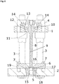
- FIG 2 a corresponding sectional view is shown. It can be seen that a sonotrode 8 designed as a punch is arranged in the middle between the four guide columns 3.
- the sonotrode 8 is rotationally symmetrical with respect to a longitudinal axis and has a circular cross section in the example shown.
- the sonotrode In order to hold the sonotrode 8 on the sonotrode plate 1, the sonotrode has a collar 10 which extends like a bead radially outwards.
- the collar 10 has a conical outer surface 12.
- the sonotrode plate 1 has an opening in which the sonotrode 10 is inserted. This opening has a conical inner surface 11.
- the inner cone 11 of the sonotrode plate 1 and the outer cone 12 of the sonotrode collar 10 are designed to correspond to one another.
- a clamping element 13 is provided in order to move the sonotrode 8 in Figure 2 to prevent upwards relative to the sonotrode plate 1.
- This clamping element 13 is essentially sleeve-shaped with a collar extending radially to the sleeve.
- the collar of the clamping element 13 has corresponding openings through which screws 14 are guided and fasten the collar of the clamping element 13 to the sonotrode plate 1.
- the sleeve itself is largely inside the opening in the sonotrode plate 1 and provides a stop surface for the sonotrode 8 or the collar 10 of the sonotrode.
- the sonotrode In the illustrated position of the clamping element 13, the sonotrode cannot be moved relative to the sonotrode plate 1 in the direction of the die plate 2, since this is caused by the corresponding cones 11, 12 is prevented. A relative movement of the sonotrode 8 in the opposite direction, however, is prevented by the contact with the clamping element 13. As a result, the clamping element 13 not only clamps the sonotrode, but also transmits power to the sonotrode 8.
- the die plate 2 has an opening with a conical inner surface 17. Received in this opening is the die 5, which has a conical outer surface 18.
- the conical outer surface 18 of the die 5 and the conical inner surface 17 of the die plate 2 are designed to correspond to one another.
- the die 5 has an opening 15, the inner contour of which at least in sections corresponds approximately to the outer contour of the sonotrode 8.
- a tape guide element 6 is provided, which is fastened to the die plate 2 with screws 7.
- the tape guide element 6 has an opening 16 which is aligned with the opening 15 in the die.
- a gap 19 is formed between the band guide element 6 and the die plate 2, through which the band-shaped punched material can be guided.
- the tape guide element can be designed to be movable so that it is movably guided between a clamping position in which the tape guide element clamps the tape on the die and / or the die plate, and a guide position in which the tape between the tape guide element and die and / or die plate becomes.
- the band guide element comes into contact with the die in sections and clamps it within the die plate.
- the tape guide element thus also functions as a die clamping element.
- the sonotrode plate 1 can now be moved via the column guide along the guide columns 3 relative to the die plate 2, with the result that the front surface of the sonotrode 8, which serves as a stamp, is inserted into the opening 15 of the die 5.
- the sonotrode 8 has a channel 9 which can be connected to a vacuum or to a compressed air source, so that the diecut is sucked onto or pushed off the end face of the sonotrode can.
- the sonotrode is excited with ultrasound only during the sealing process, but not during the stamping process. In an alternative embodiment, however, the ultrasound excitation also takes place during the stamping process.
- FIG 3 a perspective sectional view is shown, the band-shaped punched product and the raw product now being additionally shown here.
- the sonotrode plate 1 moves in the direction of the die plate 2
- the sonotrode 8 passes through the band guide element 6 moved so that the die cut, for example a membrane, is punched out of the band 20.
- the end face can now suck in the diecut until the sonotrode has passed through the opening 15 and the diecut comes to rest on the raw product 21 provided.
- the sonotrode 8 is subjected to an ultrasonic vibration, so that the diecut is welded to the raw product 21.
- connection to the vacuum source is closed and, if necessary, the channel 9 is acted upon by a fluid such as compressed air and the sonotrode plate 1 is moved away from the die plate 2 again. Thereafter, both the band-shaped material to be cut 20 and the row of raw products 21 are moved on and a new stamping and sealing process begins.
- FIG 4 A corresponding ultrasound processing device with a corresponding punch-sealing unit is shown.
- the unit has a device base 23 on which a corresponding device frame 22 is mounted.
- the die plate 2 is attached to the frame 22.
- the die plate could be attached to the device foot 23.
- a drive unit 24 is provided which engages the sonotrode plate 1 and can move it relative to the die plate 2 via the guide columns 3.
- a converter 25 is provided to apply an ultrasonic vibration to the sonotrode 8.
- the sonotrode 8 can also be equipped with an amplitude transformer. In this case, the collar can also be arranged on the section of the sonotrode which forms the amplitude transformer.
- FIG. 5 and 6 An alternative embodiment of a sonotrode 26 is shown.
- This sonotrode 26 differs from the sonotrode shown in the previous figures in that the sonotrode collar 10 is not formed in one piece with the sonotrode 26, but is shrunk onto it.
- the sonotrode collar 10 could also be welded or soldered to the sonotrode.
- the outside diameter of the collar is labeled D1 and the inside diameter of the collar is labeled D11.
- the cone angle of the collar and the inner surface of the sonotrode plate opening is preferably between 5 ° and 30 ° and most preferably around 10 °.
- L0 denotes half the wavelength of the ultrasonic vibration.
- the entire sonotrode thus has a length that corresponds to a full wavelength of the resonant ultrasonic oscillation.
- the thickness of the collar (clamping surface height) is designated L1 and is preferably at least L0 / 20 and at most L0 / 2.
- the thickness of the fret is best chosen to be L0 / 10 (one tenth of half the wavelength).
- the clamping surface height must not be chosen too small in order to ensure centering in the sonotrode plate.
- the sonotrode has only a length that corresponds to half a wavelength of the resonant ultrasonic oscillation. All other preferred dimensions mentioned also apply to the shorter version of the sonotrode.
- the sonotrode collar 10 is shrunk into the opening of the sonotrode plate.
- the band 20 is first positioned within the band guide element 6.
- the sonotrode 8 is initially in a basic position in which the stamp is positioned above the belt.
- the channel 9 is connected to a vacuum source and the sonotrode is moved downward, so that the sonotrode tip moves through the die and a punched part is punched out of the band.
- the diecut is held on the sonotrode and moved in the vicinity of the unsealed raw product. This movement is also known as the punch stroke.
- the sonotrode is subjected to ultrasound.
- the vibrating sonotrode 8 is moved somewhat in the direction of the raw product 21 during the subsequent sealing process in order to exert a welding force on the diecut. This movement is also known as the welding stroke.
- the connection between the duct and the vacuum source can be separated during the sealing process.
- the sonotrode is moved upwards again into its basic position and the band 20 is moved further within the band guide element. The next stamping and sealing process can then follow.
Landscapes
- Engineering & Computer Science (AREA)
- Mechanical Engineering (AREA)
- General Engineering & Computer Science (AREA)
- Chemical & Material Sciences (AREA)
- Combustion & Propulsion (AREA)
- Physics & Mathematics (AREA)
- Fluid Mechanics (AREA)
- Lining Or Joining Of Plastics Or The Like (AREA)
- Perforating, Stamping-Out Or Severing By Means Other Than Cutting (AREA)
- Pressure Welding/Diffusion-Bonding (AREA)
- Apparatuses For Generation Of Mechanical Vibrations (AREA)
- Details Of Cutting Devices (AREA)
Description
- Die vorliegende Erfindung betrifft eine Stanz-Siegeleinheit mit einem als Sonotrode ausgebildeten Stempel und einer Matrize, wobei die Matrize eine Öffnung aufweist und der Stempel in Stanzrichtung in die Öffnung hinein- und aus dieser herausbewegbar ist. Des Weiteren betrifft die vorliegende Erfindung eine Ultraschallbearbeitungsvorrichtung zum Stanzen von Stanzlingen aus Stanzgut und zum Siegeln der Stanzlinge an Rohprodukte.
- Es gibt in der Industrie eine Vielzahl von Anwendungen, bei denen ein Stanzling aus einem Stanzgut ausgestanzt wird und dieser in einem weiteren Verarbeitungsschritt an ein Produkt gesiegelt wird.
- Beispielsweise werden als Druckausgleichselemente dienende Membrane in elektronische Gehäuse aber auch in Leuchten und Scheinwerfer eingebaut. Diese Druckausgleichselemente ermöglichen einen Druckausgleich, was wiederum zu einer geringeren Belastung von möglicherweise vorhandenen Dichtungen und damit reduzierten Leckagen führt. Insoweit die Membran permeabel ist, kann auch Feuchtigkeit aus dem Gehäuse entweichen.
- In der Regel werden die entsprechend ausgestanzten und vorkonfektionierten Membrane über ein Trägerband bereitgestellt und mit dem Produkt, wie z.B. dem Gehäuse, verschweißt bzw. versiegelt. Alternativ können auch mittels Spritzgießen hergestellte Membranelemente gefertigt und mit dem Gehäuse verschraubt bzw. mit diesem verklipst werden.
- Kürzlich wurde von der Anmelderin eine Ultraschallbearbeitungsmaschine entwickelt, die in einem Arbeitsgang eine Membran mechanisch aus einem Materialband stanzt und mittels Ultraschall auf ein Kunststoffformteil aufsiegelt. Hierzu wurde eine herkömmliche Ultraschallbearbeitungsvorrichtung verwendet, bei der eine Ultraschallschwingeinheit bestehend aus einer Sonotrode und einem Konverter in einer mittels einer Antriebseinheit betätigbaren Vorschubeinheit gehalten wird. Dabei kann die Sonotrode ggf. über ein Amplitudentransformationsstück mit dem Konverter verbunden sein. Die Vorschubeinheit ist mit einem Gerätegestell verbunden, sodass durch Ansteuern der Antriebseinheit die Position der Ultraschallschwingeinheit relativ zu dem Maschinengestell in einer Richtung hin und her bewegt werden kann. Bei der entwickelten Maschine wurde eine Matrize, die in einer Matrizenplatte aufgenommen worden ist, fest mit dem Maschinengestell verbunden, sodass durch die Bewegung der Ultraschallschwingeinheit die Sonotrode in die Öffnung der Matrize hineinbewegt werden konnte, um die Membran aus dem Membranband auszustanzen.
- Der Vorteil dieser Maschine ist es, dass auf die Verwendung von vorgefertigten Membranen, die zunächst auf ein Trägerband appliziert werden müssen, verzichtet werden kann. Stattdessen werden die Membranen unmittelbar vor der Verbindung mit dem Produkt, wie z.B. dem Gehäuse, ausgestanzt.
- Allerdings ist es sehr aufwendig, diese Maschine zu justieren, da Stempel und Matrize exakt zueinander ausgerichtet sein müssen. Ein zuverlässiger Stanzvorgang ist nur dann sichergestellt, wenn die Innenkontur der Matrize sich nicht zu sehr von der Außenkontur der Sonotrode unterscheidet.
- Es ist daher nicht nur die Matrizenplatte exakt gegenüber dem Gestell auszurichten, sondern darüber hinaus müssen auch erhöhte Anforderungen an die Toleranzen bei der Verbindung zwischen Gestell und Transportschlitten bzw. zwischen Transportschlitten und Ultraschallschwingeinheit erfüllt werden.
- Des Weiteren kann es aufgrund der nur einseitigen Halterung der Vorschubeinheit am Gestell zu Verbiegungen gegenüber dem Gestell kommen, die sich durch entsprechende Ausrichtung der Sonotrode nicht mehr kompensieren lassen.
- Das Dokument
JP S56129130 A Fig. 1 eine Vorrichtung zur Halterung und Justierung einer Sonotrode in einem Ultraschallschweißgerät. Die Sonotrode weist in diesem Fall einen Flansch auf, der mittels einer Schraube zwischen einem unteren und einer oberen Haltering verklemmt ist. Der obere Haltering ist ebenfalls mit einer Schraube an einer Sonotrodenplatte befestigt. - Das Dokument
EP 1 043 146 A1 stellt eine Methode und eine Vorrichtung zur Anbringung von Strohhalmen an biegsamen Behältnissen mittels Ultraschallschweißtechnik vor. In diesem Dokument ist beispielsweise in den Abbildungen 1 und 2 ebenfalls eine Halterung einer Sonotrode dargestellt. - Das Dokument
CH 687366 A5 - Die Ausrichtung der Werkzeuge zueinander und insbesondere die Justierung der Sonotrode stellt bei der Inbetriebnahme eine große Herausforderung dar, so dass hierfür in der Regel ein vom Anlagenhersteller besonders geschulter Fachmann notwendig ist. Eine nicht ausreichende Ausrichtung führt zu erhöhtem Verschleiß an den Werkzeugen sowie zu Störungen des Stanz-SiegelProzesses.
- In jedem Fall ist ein Austausch der Matrize bzw. des Sonotrodenstempels, um bspw. die Größe der zu stanzenden und zu verschweißenden Membranen zu ändern, nur mit großem Aufwand möglich, der in der Regel von dem Benutzer der Ultraschallbearbeitungsvorrichtung nicht betrieben werden kann.
- Es ist daher die Aufgabe der vorliegenden Erfindung eine Stanzsiegeleinheit anzugeben, die die genannten Probleme zumindest verringert.
- Erfindungsgemäß wird dies dadurch erreicht, dass eine Sonotrodenplatte mit einer Sonotrodenplattenöffnung zur Aufnahme der Sonotrode vorgesehen ist, wobei die Sonotrode einen Bund aufweist, und die Sonotrodenplattenöffnung eine Innenkontur mit einer Anschlagsfläche und der Bund eine Außenkontur mit einer Anschlagsfläche hat, wobei die beiden Anschlagsflächen korrespondierend zueinander ausgebildet sind, so dass, wenn die Sonotrode in der Sonotrodenplattenöffnung aufgenommen ist, die Anschlagsflächen aneinander anliegen, wobei die Innenkontur einen Innenkonus und die Außenkontur einen Außenkonus, welcher korrespondierend zu dem Innenkonus ausgebildet ist, aufweist.
- Durch diese Maßnahme ist eine leichte Ausrichtung der Sonotrode gegenüber der Sonotrodenplatte möglich. Ist daher die Sonotrodenplatte einmal korrekt positioniert, kann die Sonotrode leicht gegen eine andere Sonotrode ausgetauscht werden. Sobald die korrespondierenden Anschlagsflächen aneinander liegen, ist die Sonotrode korrekt relativ zur Sonotrodenplatte positioniert.
- Die konusförmige Außenkontur des Bundes und die dazu korrespondierende Innenkontur der Sonotrodenplatte hat den Vorteil, dass die Ausrichtung der Sonotrode und damit des Stempels relativ zu der Sonotrodenplatte einfach erfolgen kann. Der Bund der Sonotrode muss lediglich in die Öffnung der Sonotrodenplatte eingelegt werden. Aufgrund der korrespondierenden konischen Abschnitte ist die Sonotrode automatisch nahezu exakt gegenüber der Sonotrodenplatte ausgerichtet. Dabei ist des Weiteren eine hohe Rundlaufgenauigkeit und eine hohe Koaxialität von Sonotrodenachse und Außenkonusachse von Vorteil.
- Der Bund kann einstückig mit der Sonotrode ausgebildet sein. Alternativ dazu kann der Bund auch getrennt von der Sonotrode gefertigt werden und mit dieser verbunden sein. Zur Befestigung des Bundes an der Sonotrode kann dieser beispielsweise auf diese aufgeschrumpft werden oder mit dieser verlötet oder verschweißt werden.
- Beispielsweise kann die Sonotrode rotationssymmetrisch, z.B. mit kreisförmigem Querschnitt, ausgeführt werden und der Bund kann in einer Richtung radial zur Rotationsachse über die Außenfläche der Sonotrode vorstehen und umlaufend ausgeführt sein. Die Sonotrodenplatte hält den Bund, sodass die Sonotrode möglichst frei schwingen kann. Alternativ kann der Stempel auch einen nicht kreisförmigen Querschnitt aufweisen. Alternativ kann der Bund in Umfangsrichtung auch unterbrochen sein.
- Ggf. weist der Bund in der Nähe der Außenfläche der Sonotrode einen Abschnitt mit verringerter axialer Ausdehnung auf, um das Schwingverhalten der Sonotrode aufgrund der Befestigung des Bundes an der Sonotrodenplatte möglichst wenig zu beeinflussen. Zudem ist der Bund vorzugsweise in einem Bereich mit der Sonotrode verbunden, in dem bei resonanter Anregung der Sonotrode mit einer Ultraschallschwingung ein Schwingungsminimum der longitudinalen Schwingung liegt.
- Zur Befestigung der Sonotrode an der Sonotrodenplatte ist in einer bevorzugten Ausführungsform ein Klemmelement vorgesehen, dass derart angeordnet ist, dass es eine Bewegung der Sonotrode bzw. des Sonotrodenbundes in axialer Richtung (Stanzrichtung) relativ zur Sonotrodenplatte verhindert. Dieses Klemmelement kann bspw. aus einer Hülse mit Kragenelement bestehen, wobei die Hülse innerhalb der Sonotrodenplattenöffnung positioniert ist und das Kragenelement an der Sonotrodenplatte befestigt ist. Die Befestigung an der Sonotrodenplatte kann bspw. mit Hilfe von einer oder mehrerer Schrauben erfolgen. Alternativ kann das Klemmelement auch als Muffe mit Außengewinde ausgebildet sein, welches in ein Innengewinde in der Sonotrodenplatte eingeschraubt werden kann.
- In einer weiteren bevorzugten Ausführungsform ist die Matrize an der Matrizenplatte befestigt und die Matrizenplatte weist eine Matrizenplattenöffnung auf, in die die Matrize eingesetzt ist. Bspw. kann die Matrizenplattenöffnung einen Innenkonus und die Matrize einen Außenkonus aufweisen, wobei der Außenkonus der Matrize korrespondierend zu dem Innenkonus der Matrizenplattenöffnung ausgebildet ist. Auch hier kann die Matrize auf einfache Weise relativ zur Matrizenplattenöffnung orientiert werden. Alternativ sind auch nichtkonische korrespondierende Anschlagsflächen möglich. Die Matrize ist vorzugsweise einteilig ausgebildet. Alternativ kann sie auch mehrteilig ausgebildet sein.
- In einer bevorzugten Ausführungsform ist eine Matrizenklemmeinheit vorgesehen, welche an der Matrizenplatte vorzugsweise mit einer oder mehreren Schrauben befestigt ist und vorzugsweise zumindest abschnittsweise mit der Matrize in Kontakt steht.
- Die Matrizenklemmeinheit kann eine Öffnung aufweisen, die mit der Matrizenöffnung fluchtet, wobei vorzugsweise zwischen Matrizenklemmeinheit und Matrize abschnittsweise ein Spalt zur Zuführung von Stanzgut gebildet wird. Die Matrizenklemmeinheit dient dann auch zur Führung des Stanzgutes.
- Um die Herstellung von Sonotrodenplatte und Matrizenplatte zu vereinfachen, können diese aufeinander gelegt, miteinander verschraubt und dann die Öffnungen mit den Innenkonen eingebracht werden. Daher ist es bevorzugt, wenn die Innenkonen der Sonotrodenplatte und der Matrizenplatte sowie die Außenkonen von Sonotrodenbund und Matrize jeweils den gleichen Konuswinkel aufweisen.
- In einer weiteren bevorzugten Ausführungsform ist die Sonotrodenplatte über eine Geradführung und vorzugsweise über eine Säulenführung mit der Matrize oder der Matrizenplatte, an der die Matrize befestigt ist, verbunden.
- Unter einer Säulenführung wird eine Führung verstanden, die mindestens eine Führungssäule und mindestens eine Führungsbuchse umfasst. Dabei kann die Führungssäule innerhalb der Führungsbuchse gleitend oder wälzend bewegt werden. Beispielsweise kann die Führungssäule an der Matrizenplatte befestigt sein und die Sonotrodenplatte eine Führungsbuchse aufweisen, sodass durch eine Bewegung der Platte relativ zur Führungssäule eine Relativbewegung zwischen Sonotrodenplatte und Matrizenplatte verwirklicht wird.
- Dabei kann die Führungsbuchse sowohl als separates Bauteil an der Sonotrodenplatte befestigt sein oder einstückig in die Sonotrodenplatte eingeformt sein.
- Mit anderen Worten ist nun die Sonotrodenplatte, welche die Sonotrode hält, und die Matrizenplatte, welche die Matrize hält, direkt miteinander über eine Säulenführung verbunden und nicht, wie im Stand der Technik, über ein Transportschlitten, der wiederum mit dem Maschinengestell verbunden ist.
- Alternativ kann die Führungssäule an der Sonotrodenplatte befestigt sein und die Matrizenplatte eine Führungsbuchse aufweisen.
- Dadurch kann eine Einrichtung der Einheit, d.h. eine Ausrichtung zwischen Sonotrode und Matrize, sogar außerhalb der Ultraschallbearbeitungsvorrichtung erfolgen.
- In einer bevorzugten Ausführungsform weist die Säulenführung mindestens zwei Säulen auf, die mit der Matrizenplatte verschraubt sind. Des Weiteren weist die Sonotrodenplatte Führungsöffnungen zur Aufnahme der Säulen auf, wobei vorzugsweise zwischen den Säulen und den Führungsöffnungen jeweils eine Führungshülse angeordnet ist.
- Aufgrund der Säulenführung von Sonotrodenplatte und Matrizenplatte sind diese mit sehr hoher Genauigkeit zueinander ausgerichtet. Die Ausbildung von Matrize und/oder Sonotrodenbund mit Außenkonus kann nun eine präzise Ausrichtung von Matrize bzw. Sonotrodenbund zu Matrizenplatte bzw. Sonotrodenplatte erfolgen.
- In einer besonders bevorzugten Ausführungsform weist die Sonotrode einen Fluidkanal mit einem Einlass auf, der an der der Matrize zugewandte Fläche der Sonotrode angeordnet ist. Der Auslass des Fluidkanals ist mit einer Vakuumquelle oder Druckluftquelle verbindbar.
- Durch Anlegen eines Vakuums kann die Führung des Stanzlings nach dem Ausstanzen bis zur Siegelposition verbessert werden, da der Stanzling am Stempel gehalten wird. Nach Beendigung des Siegelvorgangs kann der Fluidkanal mit Druckluft beaufschlagt werden, um den gesiegelten Stanzling vom Stempel zu lösen, ohne dass die Gefahr besteht, die Siegelung zu beschädigen.
- Des Weiteren betrifft die vorliegende Erfindung eine Ultraschallbearbeitungsvorrichtung zum Stanzen von Stanzlingen aus Stanzgut und zum Siegeln der Stanzlinge an Rohprodukte. Erfindungsgemäß wird eine Stanzsiegeleinheit wie beschrieben verwendet.
- Die Ultraschallbearbeitungsvorrichtung weist in einer bevorzugten Ausführungsform ein Gestell auf, an welchem die Matrizenplatte befestigt ist. Des Weiteren ist eine Antriebseinheit vorgesehen, welche an der Sonotrodenplatte angreift und diese relativ zur Matrizenplatte bewegen kann. Zwischen Antriebseinheit und Sonotrodenplatte kann eine Ausgleichskupplung vorgesehen sein, mit der kleinere Abweichung zwischen der Bewegungsrichtung der Antriebseinheit und der Bewegungsrichtung der Säulenführung ausgeglichen werden können. Die Antriebseinheit kann beispielsweise einen Kolben aufweisen, der hydraulisch oder pneumatisch betätigt werden kann. Da sich die von der Sonotrode aufzubringenden Kräfte beim Stanzen und beim Siegeln unterscheiden, kann die Antriebseinheit zwei Kolben mit unterschiedlichen effektiven Querschnitten aufweisen, wobei der eine Kolben zum Aufbringen der Stanzkraft und der andere Kolben zum Aufbringen der Siegelkraft vorgesehen ist.
- Alternativ kann die Antriebseinheit einen elektrischen Motor, z. B. einen Servomotor, aufweisen.
- In einer weiteren besonders bevorzugten Ausführungsform ist eine Zuführung von Stanzgut und eine Zuführung von Rohprodukten vorgesehen, wobei die Zuführung von Stanzgut und die Zuführung von Rohprodukten auf gegenüberliegenden Seiten der Matrizenplatte angeordnet sind.
- Weitere Vorteile, Merkmale und Anwendungsmöglichkeiten der vorliegenden Erfindung werden deutlich anhand der folgenden Beschreibung einer bevorzugten Ausführungsform und der dazugehörigen Figuren. Es zeigen:
-
Figur 1 eine perspektivische Ansicht einer erfindungsgemäßen Stanzsiegeleinheit, -
Figur 2 eine Schnittansicht der Stanzsiegeleinheit vonFigur 1 , -
Figur 3 eine perspektivische Schnittansicht der Stanzsiegeleinheit vonFigur 1 , -
Figur 4 eine perspektivische Ansicht einer Ultraschallbearbeitungseinheit mit der Stanzsiegeleinheit derFiguren 1 bis 4 , -
Figur 5 eine Seitenansicht einer alternativen Ausführungsform einer Sonotrode einer erfindungsgemäßen Stanzsiegeleinheit und -
Figur 6 eine Schnittansicht der Ausführungsform der Sonotrode vonFigur 5 . - In
Figur 1 ist eine Ausführungsform einer erfindungsgemäßen Stanzsiegeleinheit gezeigt. Die Stanzsiegeleinheit weist eine Sonotrodenplatte 1 und eine Matrizenplatte 2 auf. Die beiden Platten sind über eine Säulenführung miteinander verbunden. Die Säulenführung weist vier Führungssäulen 3 auf, die mit der Matrizenplatte 2 verschraubt sind und innerhalb von Führungshülsen 4, die in entsprechenden Bohrungen in der Sonotrodenplatte 1 befestigt sind, beweglich geführt sind. Die Sonotrodenplatte 1 kann dann gegenüber der Matrizenplatte 2 entlang der Führungssäulen 3 hin und her bewegt werden. Über die Säulenführung ist sichergestellt, dass die Sonotrodenplatte 1 und die Matrizenplatte 2 nahezu perfekt parallel zueinander angeordnet sind. - In
Figur 2 ist eine entsprechende Schnittansicht dargestellt. Man erkennt, dass in der Mitte zwischen den vier Führungssäulen 3 eine als Stanzstempel ausgebildete Sonotrode 8 angeordnet ist. Die Sonotrode 8 ist rotationssymmetrisch in Bezug auf eine Längsachse ausgebildet und hat im gezeigten Beispiel einen kreisförmigen Querschnitt. Um die Sonotrode 8 an der Sonotrodenplatte 1 zu halten, weist die Sonotrode einen Bund 10 auf, der sich wulstartig radial nach außen erstreckt. Der Bund 10 weist eine konische Außenfläche 12 auf. Die Sonotrodenplatte 1 hat eine Öffnung, in der die Sonotrode 10 eingesetzt ist. Diese Öffnung weist eine konische Innenfläche 11 auf. Der Innenkonus 11 der Sonotrodenplatte 1 und der Außenkonus 12 des Sonotrodenbundes 10 sind korrespondierend zueinander ausgebildet. Dies führt zu einer exakten Ausrichtung der Achse der Sonotrode senkrecht zur Fläche der Sonotrodenplatte. Um eine Bewegung der Sonotrode 8 inFigur 2 nach oben relativ zur Sonotrodenplatte 1 zu verhindern, ist ein Klemmelement 13 vorgesehen. Dieses Klemmelement 13 ist im Wesentlichen hülsenförmig mit einem sich radial zur Hülse erstreckendem Kragen. Der Kragen des Klemmelementes 13 weist entsprechende Öffnungen auf, durch die Schrauben 14 geführt sind und den Kragen des Klemmelementes 13 an der Sonotrodenplatte 1 befestigen. Die Hülse selbst befindet sich größtenteils innerhalb der Öffnung in der Sonotrodenplatte 1 und stellt eine Anschlagsfläche für die Sonotrode 8 bzw. den Bund 10 der Sonotrode zur Verfügung. In der dargestellten Position des Klemmelementes 13 kann die Sonotrode relativ zur Sonotrodenplatte 1 in Richtung der Matrizenplatte 2 nicht bewegt werden, da dies durch die korrespondierenden Konusse 11, 12 verhindert wird. Eine Relativbewegung der Sonotrode 8 in die umgekehrte Richtung wird hingegen durch die Anlage am Klemmelement 13 verhindert. Im Ergebnis bewirkt das Klemmelement 13 nicht nur ein Klemmen der Sonotrode, sondern auch eine Kraftübertragung auf die Sonotrode 8. - Die Matrizenplatte 2 weist in gleicher Weise eine Öffnung mit konischer Innenfläche 17 auf. Aufgenommen in dieser Öffnung ist die Matrize 5, welche eine konische Außenfläche 18 hat. Auch hier sind die konische Außenfläche 18 der Matrize 5 und die konische Innenfläche 17 der Matrizenplatte 2 korrespondierend zueinander ausgeführt. Die Matrize 5 weist eine Öffnung 15 auf, deren Innenkontur zumindest abschnittsweise in etwa der Außenkontur der Sonotrode 8 entspricht. Des Weiteren ist ein Bandführungselement 6 vorgesehen, welches mit Schrauben 7 an der Matrizenplatte 2 befestigt ist. Das Bandführungselement 6 weist eine Öffnung 16 auf, die mit der Öffnung 15 in der Matrize fluchtet. Zwischen dem Bandführungselement 6 und der Matrizenplatte 2 wird ein Spalt 19 gebildet, durch den das bandförmige Stanzgut geführt werden kann. Alternativ dazu kann das Bandführungselement beweglich ausgebildet sein, so dass es zwischen einer Klemmposition, in der das Bandführungselement das Band an der Matrize und/oder der Matrizenplatte einklemmt, und einer Führungsposition, in der das Band zwischen Bandführungselement und Matrize und/oder Matrizenplatte beweglich geführt wird. Bei der gezeigten Ausführungsform tritt das Bandfürungselement abschnittsweis mit der Matrize in Kontakt und klemmt diese innerhalb der Matrizenplatte fest. Das Bandführungselement fungiert somit auch als Matrizenklemmelement.
- Bei der gezeigten Ausführungsform kann nun die Sonotrodenplatte 1 über die Säulenführung entlang der Führungssäulen 3 relativ zur Matrizenplatte 2 bewegt werden mit der Folge, dass die Frontfläche der Sonotrode 8, die als Stempel dient, in die Öffnung 15 der Matrize 5 eingeführt wird. Befindet sich Stanzgut in dem Spalt 19 zwischen Matrize 5 und Bandführung 6, so wird ein Stanzling in Größe der Stirnfläche der Sonotrode 8 aus dem Band ausgestanzt und durch die Öffnung 15 nach unten transportiert, um im nächsten Bearbeitungsschritt mit dem Rohprodukt mittels Ultraschall verschweißt zu werden. Um einen zuverlässigen Transport des Stanzlinges durch die Öffnung 15 in der Matrize sicherzustellen, weist die Sonotrode 8 einen Kanal 9 auf, der mit einem Vakuum oder mit einer Druckluftquelle verbunden werden kann, sodass der Stanzling an die Stirnfläche der Sonotrode gesaugt oder von dieser abgestoßen werden kann. In einer bevorzugten Ausführungsform wird die Sonotrode nur während des Siegelprozesses, nicht aber während des Stanzprozesses mit Ultraschall angeregt. In einer alternativen Ausführungsform erfolgt jedoch die Ultraschallanregung auch während des Stanzprozesses.
- In
Figur 3 ist eine perspektivische Schnittansicht gezeigt, wobei hier jetzt zusätzlich noch das bandförmige Stanzgut sowie das Rohprodukt dargestellt ist. Bei der Bewegung der Sonotrodenplatte 1 in Richtung der Matrizenplatte 2 wird die Sonotrode 8 durch das Bandführungselement 6 hindurch bewegt, sodass der Stanzling, z.B. eine Membran aus dem Band 20 ausgestanzt wird. Aufgrund des Kanals 9 kann nun die Stirnfläche den Stanzling ansaugen, bis die Sonotrode die Öffnung 15 durchwandert hat und der Stanzling auf dem bereitgestellten Rohprodukt 21 zu liegen kommt. In dieser Position wird die Sonotrode 8 mit einer Ultraschallschwingung beaufschlagt, sodass der Stanzling mit dem Rohprodukt 21 verschweißt wird. Die Verbindung zur Vakuumquelle wird geschlossen und ggf. der Kanal 9 mit einem Fluid wie z.B. Druckluft beaufschlagt und die Sonotrodenplatte 1 wieder von der Matrizenplatte 2 weg bewegt. Danach werden sowohl das bandförmige Stanzgut 20 als auch die Reihe der Rohprodukte 21 weiter bewegt und ein neuer Stanzsiegelvorgang beginnt. - In
Figur 4 ist eine entsprechende Ultraschallbearbeitungseinrichtung mit einer entsprechenden Stanzsiegeleinheit gezeigt. Die Einheit weist einen Gerätefuß 23 auf, an dem ein entsprechendes Gerätegestell 22 montiert ist. Die Matrizenplatte 2 ist am Gestell 22 befestigt. Alternativ könnte die Matrizenplatte am Gerätefuß 23 befestigt sein. Eine Antriebseinheit 24 ist vorgesehen, die an der Sonotrodenplatte 1 angreift und diese über die Führungssäulen 3 relativ zur Matrizenplatte 2 bewegen kann. Zum Beaufschlagen der Sonotrode 8 mit einer Ultraschallschwingung ist ein Konverter 25 vorgesehen. Die Sonotrode 8 kann auch mit einem Amplitudentransformator ausgestattet sein. In diesem Fall kann der Bund auch an dem den Amplitudentransformator bildenden Abschnitt der Sonotrode angeordnet sein. - In den
Figuren 5 und6 ist eine alternative Ausführungsform einer Sonotrode 26 dargestellt. Diese Sonotrode 26 unterscheidet sich von der in den vorherigen Figuren dargestellten Sonotrode dadurch, dass der Sonotrodenbund 10 nicht einstückig mit der Sonotrode 26 ausgebildet ist, sondern auf diese aufgeschrumpft ist. Alternativ könnte der Sonotrodenbund 10 auch an die Sonotrode angeschweißt oder angelötet sein. - Für alle Ausführungsformen gelten die folgenden bevorzugten Abmessungen. Der Außendurchmesser des Bundes ist mit D1 und der Innendurchmesser des Bundes ist mit D11 bezeichnet. Der Konuswinkel des Bundes und der Innenfläche der Sonotrodenplattenöffnung liegt vorzugsweise zwischen 5° und 30° und am besten bei etwa 10°. Mit L0 ist die halbe Wellenlänge der Ultraschallschwingung bezeichnet. Die gesamte Sonotrode hat somit eine Länge, die einer vollen Wellenlänge der resonanten Ultraschallschwingung entspricht. Die Dicke des Bundes (Klemmflächenhöhe) ist mit L1 bezeichnet und beträgt vorzugsweise mindestens L0/20 und höchstens L0/2. Am besten wird die Dicke des Bundes zu L0/10 (Ein Zehntel der halben Wellenlänge) gewählt. Die Klemmflächenhöhe darf nicht zu klein gewählt werden, um eine zentrierende Aufnahme in der Sonotrodenplatte zu gewährleisten.
- In einer alternativen Ausführungsform hat die Sonotrode nur eine Länge, die einer halben Wellenlänge der resonanten Ultraschallschwingung entspricht. Alle anderen genannten, bevorzugten Abmessungen gelten auch für die kürzere Ausführung der Sonotrode.
- In einer weiteren Ausführungsform ist vorgesehen, dass der Sonotrodenbund 10 in die Öffnung der Sonotrodenplatte eingeschrumpft wird.
- Zur Durchführung des Stanz-Siegelvorgangs wird zunächst das Band 20 innerhalb des Bandführungselementes 6 positioniert. Die Sonotrode 8 ist zunächst in einer Grundposition, in der der Stempel oberhalb des Bandes positioniert ist. Nun wird der Kanal 9 mit einer Vakuumquelle verbunden und die Sonotrode nach unten bewegt, so dass sich die Sonotrodenspitze durch die Matrize hindurchbewegt und einen Stanzling aus dem Band stanzt. Dadurch, das am Kanal 9 Vakuum anliegt, wird der Stanzling an der Sonotrode gehalten und in die Nähe des unversiegelten Rohproduktes bewegt. Diese Bewegung wird auch als Stanzhub bezeichnet. Unmittelbar bevor und spätestens wenn der Stanzling das Rohprodukt 21 berührt wird die Sonotrode mit Ultraschall beaufschlagt. Die schwingende Sonotrode 8 wird während des sich anschließenden Siegelvorgangs etwas in Richtung des Rohproduktes 21 bewegt, um eine Schweißkraft auf den Stanzling auszuüben. Diese Bewegung wird auch als Schweißhub bezeichnet. Während des Siegelvorgangs kann die Verbindung zwischen Kanal und Vakuumquelle getrennt werden.
- Sobald der Siegelvorgang beendet ist, wird die Sonotrode wieder nach oben in ihre Grundposition bewegt und das Band 20 innerhalb des Bandführungselementes weiterbewegt. Danach kann sich der nächste Stanz-Siegelvorgang anschließen.
-
- 1
- Sonotrodenplatte
- 2
- Matrizenplatte
- 3
- Führungssäule
- 4
- Führungshülse
- 5
- Matrize
- 6
- Bandführungselement
- 7
- Schrauben
- 8
- Sonotrode
- 9
- Kanal
- 10
- Sonotrodenbund
- 11
- konische Innenfläche
- 12
- konische Außenfläche
- 13
- Klemmelement
- 14
- Schrauben
- 15
- Öffnung
- 16
- Öffnung
- 17
- konische Innenfläche
- 18
- konische Außenfläche
- 19
- Spalt
- 20
- Band
- 21
- Rohrprodukt
- 22
- Gerätegestell
- 23
- Gerätefuß
- 24
- Stanz-Siegel-Einheit
- 25
- Konverter
- 26
- Sonotrode
Claims (14)
- Stanz-Siegel-Einheit mit einem als Sonotrode (8) ausgebildeten Stempel und einer Matrize (5), wobei die Matrize (5) eine Öffnung (15) aufweist und der Stempel in Stanzrichtung in die Öffnung (15) hinein- und aus dieser herausbewegbar ist, dadurch gekennzeichnet, dass eine Sonotrodenplatte (1) mit einer Sonotrodenplattenöffnung zur Aufnahme der Sonotrode vorgesehen ist, wobei die Sonotrode (8) einen Bund (10) aufweist, und die Sonotrodenplattenöffnung eine Innenkontur mit einer Anschlagsfläche und der Bund eine Außenkontur mit einer Anschlagsfläche hat, wobei die beiden Anschlagsflächen korrespondierend zueinander ausgebildet sind, so dass, wenn die Sonotrode in der Sonotrodenplattenöffnung aufgenommen ist, die Anschlagsflächen aneinander anliegen, wobei die Innenkontur einen Innenkonus und die Außenkontur einen Außenkonus, welcher korrespondierend zu dem Innenkonus ausgebildet ist, aufweist.
- Stanz-Siegel-Einheit nach Anspruch 1, dadurch gekennzeichnet, dass der Bund umlaufend ausgeführt ist.
- Stanz-Siegel-Einheit nach Anspruch 1 oder 2, dadurch gekennzeichnet, dass ein Klemmelement (13) vorgesehen ist, welches sowohl mit der Sonotrodenplatte (1) als auch dem Bund in Kontakt tritt und derart angeordnet ist, dass es eine lineare Relativbewegung zwischen Bund und Sonotrodenplatte (1) verhindert, wobei vorzugsweise das Klemmelement (13) aus einer Hülse mit Kragenelement besteht, wobei die Hülse innerhalb der Sonotrodenplattenöffnung positioniert ist und das Kragenelement an der Sonotrodenplatte (1) vorzugsweise mit Hilfe von einer oder mehreren Schrauben (7, 14) befestigt ist.
- Stanz-Siegel-Einheit nach einem der Ansprüche 1 bis 3, dadurch gekennzeichnet, dass die Matrize (5) an einer Matrizenplatte (2) befestigt ist und die Matrizenplatte (2) eine Matrizenplattenöffnung aufweist, in die die Matrize (5) eingesetzt ist.
- Stanz-Siegel-Einheit nach Anspruch 4, dadurch gekennzeichnet, dass die Matrizenplattenöffnung eine Innenkontur und die Matrize einen Außenkontur hat, wobei die Außenkontur der Matrize und die Innenkontur der Matrizenplatte korrespondierend zueinander ausgeführt sind, wobei vorzugsweise die Innenkontur der Matrizenplatte einen Innenkonus und die Außenkontur der Matrize (5) einen Außenkonus aufweist, wobei der Außenkonus der Matrize (5) korrespondierend zu dem Innenkonus der Matrizenplattenöffnung ausgebildet ist.
- Stanz-Siegel-Einheit nach Anspruch 5, dadurch gekennzeichnet, dass eine Matrizenklemmeinheit vorgesehen ist, welche an der Matrizenplatte (2) vorzugsweise mit einer oder mehreren Schrauben (7, 14) befestigt ist und zumindest abschnittsweise mit der Matrize (5) in Kontakt steht.
- Stanz-Siegel-Einheit nach Anspruch 6, dadurch gekennzeichnet, dass die Matrizenklemmeinheit eine Öffnung (15, 16) aufweist, die mit der Matrizenöffnung fluchtet, wobei vorzugsweise zwischen Matrizenklemmeinheit und Matrize (5) abschnittsweise ein Spalt (19) zur Zuführung von Stanzgut gebildet wird.
- Stanz-Siegel-Einheit nach einem der Ansprüche 5 bis 6, dadurch gekennzeichnet, dass die Innenkonen der Sonotrodenplatte (1) und der Matrizenplatte (2) sowie die Außenkonen von Sonotrodenbund (10) und Matrize (5) jeweils den gleichen Konuswinkel aufweisen.
- Stanz-Siegel-Einheit nach einem der Ansprüche 1 bis 8, dadurch gekennzeichnet, dass die Sonotrodenplatte über eine Geradführung mit der Matrize (5) oder der Matrizenplatte (2), an der die Matrize (5) befestigt ist, verbunden ist, wobei vorzugsweise die Geradführung eine Säulenführung ist.
- Stanz-Siegel-Einheit nach Anspruch 9, dadurch gekennzeichnet, dass die Geradführung eine Säulenführung ist und mindestens zwei Säulen aufweist, die mit der Matrizenplatte (2) verschraubt sind, und die Sonotrodenplatte (1) Führungsöffnungen zur Aufnahme der Säulen aufweist, wobei vorzugsweise zwischen den Säulen und den Führungsöffnungen jeweils eine Führungshülse (4) angeordnet ist.
- Stanz-Siegel-Einheit nach einem der Ansprüche 1 bis 10, dadurch gekennzeichnet, dass die Sonotrode (8) einen Fluidkanal mit einem Einlass, der an der der Matrize (5) zugewandten Fläche der Sonotrode (8) angeordnet ist, und einem Auslass, der mit einer Vakuumquelle und/oder Druckluftquelle verbindbar ist.
- Ultraschallbearbeitungsvorrichtung zum Stanzen von Stanzlingen aus Stanzgut und zum Siegeln der Stanzlinge an Rohprodukte, dadurch gekennzeichnet, dass eine Stanz-Siegel-Einheit nach einem der Ansprüche 1 bis 11 vorgesehen ist.
- Ultraschallbearbeitungsvorrichtung nach Anspruch 12, dadurch gekennzeichnet, dass ein Gestell, an welchem die Matrizenplatte (2) befestigt ist, und eine Antriebseinheit, welche an der Sonotrodenplatte (1) angreift und diese relativ zur Matrizenplatte (2) bewegen kann, vorgesehen ist.
- Ultraschallbearbeitungsvorrichtung nach Anspruch 12 oder 13, dadurch gekennzeichnet, dass eine Zuführung von Stanzgut und eine Zuführung von Rohprodukten vorgesehen ist, wobei die Zuführung von Stanzgut und die Zuführung von Rohprodukten auf gegenüberliegenden Seiten der Matrizenplatte (2) angeordnet sind.
Applications Claiming Priority (2)
| Application Number | Priority Date | Filing Date | Title |
|---|---|---|---|
| DE102016107958.8A DE102016107958A1 (de) | 2016-04-28 | 2016-04-28 | Stanz-Siegeleinheit und Ultraschallbearbeitungsvorrichtung mit einer solchen |
| PCT/EP2017/059869 WO2017186764A1 (de) | 2016-04-28 | 2017-04-26 | Stanz-siegeleinheit und ultraschallbearbeitungsvorrichtung mit einer solchen |
Publications (2)
| Publication Number | Publication Date |
|---|---|
| EP3448656A1 EP3448656A1 (de) | 2019-03-06 |
| EP3448656B1 true EP3448656B1 (de) | 2020-02-26 |
Family
ID=58664685
Family Applications (1)
| Application Number | Title | Priority Date | Filing Date |
|---|---|---|---|
| EP17720758.6A Active EP3448656B1 (de) | 2016-04-28 | 2017-04-26 | Stanz-siegeleinheit und ultraschallbearbeitungsvorrichtung mit einer solchen |
Country Status (6)
| Country | Link |
|---|---|
| US (1) | US10393152B2 (de) |
| EP (1) | EP3448656B1 (de) |
| JP (1) | JP6590390B2 (de) |
| CN (1) | CN109153188B (de) |
| DE (1) | DE102016107958A1 (de) |
| WO (1) | WO2017186764A1 (de) |
Families Citing this family (6)
| Publication number | Priority date | Publication date | Assignee | Title |
|---|---|---|---|---|
| DE102016107958A1 (de) | 2016-04-28 | 2017-11-02 | Herrmann Ultraschalltechnik Gmbh & Co. Kg | Stanz-Siegeleinheit und Ultraschallbearbeitungsvorrichtung mit einer solchen |
| IT201700117582A1 (it) * | 2017-10-18 | 2019-04-18 | Gd Spa | Unità di taglio di un nastro di substrato per un dispositivo di generazione di aerosol e relativo gruppo di taglio. |
| DE112018007528A5 (de) | 2018-04-27 | 2021-01-14 | Telsonic Holding Ag | Verfahren und Vorrichtung zum Applizieren eines flexiblen Flächengebildes auf ein Basisformteil, sowie Bauteil mit einem flexiblen Flächengebilde auf einem Basisformteil |
| CN110757828B (zh) * | 2019-11-27 | 2024-02-06 | 烟台迪康环境科技有限公司 | 半自动制作堆料滤网的装置 |
| DE102021110762A1 (de) | 2021-04-27 | 2022-10-27 | Herrmann Ultraschalltechnik Gmbh & Co. Kg | Ultraschallschwingeinheit mit stoffschlüssig verbundenen Komponenten |
| CN118418469A (zh) * | 2024-07-02 | 2024-08-02 | 宁波浙隆汽车零部件有限公司 | 一种用于汽车踏板灯无缝焊接机构 |
Family Cites Families (13)
| Publication number | Priority date | Publication date | Assignee | Title |
|---|---|---|---|---|
| JPS6011336B2 (ja) * | 1974-11-26 | 1985-03-25 | キヤノン株式会社 | 中間鏡筒 |
| JPS56129130A (en) | 1980-03-14 | 1981-10-09 | Shimada Phys & Chem Ind Co Ltd | Cutting and fusion bonding of thermoplastic resin tape |
| DE9212560U1 (de) * | 1992-09-17 | 1993-03-18 | Branson Ultraschall Niederlassung der Emerson Technologies GmbH & Co, 6057 Dietzenbach | Ultraschall-Schweißeinrichtung, insbesondere für Kleinteile |
| CH687366A5 (de) | 1993-06-04 | 1996-11-29 | Emporia Maschinen Ag | Vorrichtung zum Ausstanzen eines Fuegeteils und zum Verschweissen desselben mit einem Werkstueck, sowie Sonotrode fuer den Gebrauch in einer solchen Vorrichtung. |
| SE519828C2 (sv) * | 1999-04-08 | 2003-04-15 | Sandvik Ab | Skär av en hårdmetallkropp med en bindefasanrikad ytzon och en beläggning och sätt att framställa denna |
| ES2175920T3 (es) | 1999-04-08 | 2002-11-16 | Robino & Galandrino Spa | Metodo y aparato para sellar pajillas de bolsas flexibles. |
| SG157957A1 (en) * | 2003-01-29 | 2010-01-29 | Interplex Qlp Inc | Package for integrated circuit die |
| DE102004018309B4 (de) * | 2004-04-13 | 2009-01-02 | Maschinenfabrik Spaichingen Gmbh | Vorrichtung zum Stanzen und Schweißen oder Kleben von Werkstücken |
| DE102005060026B4 (de) * | 2005-12-14 | 2013-08-29 | Ms Spaichingen Gmbh | Vorrichtung zur Durchführung von Stanz- und/oder Schweiß- und/oder Klebearbeiten |
| DE102006020418A1 (de) * | 2006-04-26 | 2007-10-31 | Herrmann Ultraschalltechnik Gmbh & Co. Kg | Vorrichtung zum Bearbeiten von Werkstücken mittels Ultraschall |
| US9393766B2 (en) | 2011-05-09 | 2016-07-19 | Boehringer Ingelheim Microparts Gmbh | Process for joining a foil or a membrane |
| DE102013223379A1 (de) * | 2013-11-15 | 2015-05-21 | Ms Spaichingen Gmbh | Verfahren und Vorrichtung zum Stanzen und Verbinden von Kunststoffteilen |
| DE102016107958A1 (de) | 2016-04-28 | 2017-11-02 | Herrmann Ultraschalltechnik Gmbh & Co. Kg | Stanz-Siegeleinheit und Ultraschallbearbeitungsvorrichtung mit einer solchen |
-
2016
- 2016-04-28 DE DE102016107958.8A patent/DE102016107958A1/de not_active Withdrawn
-
2017
- 2017-04-26 CN CN201780026424.7A patent/CN109153188B/zh not_active Expired - Fee Related
- 2017-04-26 EP EP17720758.6A patent/EP3448656B1/de active Active
- 2017-04-26 US US16/084,592 patent/US10393152B2/en active Active
- 2017-04-26 JP JP2018554732A patent/JP6590390B2/ja not_active Expired - Fee Related
- 2017-04-26 WO PCT/EP2017/059869 patent/WO2017186764A1/de not_active Ceased
Non-Patent Citations (1)
| Title |
|---|
| None * |
Also Published As
| Publication number | Publication date |
|---|---|
| JP6590390B2 (ja) | 2019-10-16 |
| EP3448656A1 (de) | 2019-03-06 |
| US10393152B2 (en) | 2019-08-27 |
| WO2017186764A1 (de) | 2017-11-02 |
| JP2019514723A (ja) | 2019-06-06 |
| CN109153188A (zh) | 2019-01-04 |
| US20190078591A1 (en) | 2019-03-14 |
| CN109153188B (zh) | 2020-03-06 |
| DE102016107958A1 (de) | 2017-11-02 |
Similar Documents
| Publication | Publication Date | Title |
|---|---|---|
| EP3448656B1 (de) | Stanz-siegeleinheit und ultraschallbearbeitungsvorrichtung mit einer solchen | |
| EP1849583B1 (de) | Vorrichtung zum Bearbeiten von Werkstücken mittels Ultraschall | |
| DE102016114026B4 (de) | Vorrichtung zum Prägen einer Vertiefung in ein plattenartiges Werkstück und Durchstanzen der geprägten Vertiefung | |
| EP2483167B1 (de) | Vorrichtung zum handhaben eines folienartigen abdeckstreifens an einer packstoffbahn für einen verpackungsbehälter | |
| DE3835566A1 (de) | Verfahren und vorrichtung zum befestigen eines hohlkoerpers an einem blech od. dgl. | |
| EP3505270B1 (de) | Setzeinheit für eine stanznietvorrichtung, stanznietvorrichtung und verfahren zum herstellen einer solchen | |
| DE102005039214A1 (de) | Verfahren zum Verbinden des Stoß von Dichtungsprofilen sowie Vorrichtung zu dessen Durchführung | |
| DE102008006864A1 (de) | Verfahren und Vorrichtung zur Lochung eines Werkstücks | |
| WO1998017412A1 (de) | Einrichtung zum formen eines spiralrohres | |
| DE102013217213A1 (de) | Verfahren zum einstanzen und befestigen eines befestigungselements und entsprechende matrize | |
| EP3117925B1 (de) | Stanznietvorrichtung und fertigungsvorrichtung | |
| EP2873512A1 (de) | Verfahren und Vorrichtung zum Stanzen und Verbinden von Kunststoffteilen | |
| DE112015001794B4 (de) | Führungsmechanismus und Verfahren zu dessen Herstellung | |
| DE102016212548B4 (de) | Betätigungseinheit eines fluidbetätigten Membranantriebes sowie Verfahren zu ihrer Herstellung und damit ausgestatteter Membranantrieb | |
| DE19911125C1 (de) | Verfahren und Vorrichtung zum Trennen oder Lochen eines Werkstücks unter Einfluß eines unter Hochdruck stehenden Druckmediums | |
| DE102018205621A1 (de) | Stanznietvorrichtung mit Zuführeinheit für Niete | |
| EP3335807A1 (de) | Sonotrode sowie schwingeinheit mit einer solchen sonotrode | |
| DE19842104B4 (de) | Stanznietverfahren | |
| DE102017208676A1 (de) | Verfahren zum Einbringen eines Lötdepots, Bauteil mit Lötdepot und Fügevorrichtung zum Einbringen eines Lötdepots | |
| EP0882546A1 (de) | Versorgungssystem zum Zuführen von Verbindungselementen von einer Versorgungseinheit an einen Stanzkopf | |
| DE10234534B3 (de) | Spritzgußwerkzeug zum Umspritzen kleinformatiger Stanzteile | |
| EP2944440B1 (de) | Stanzvorrichtung und stanzverfahren zur herstellung von formetiketten | |
| DE69510349T2 (de) | Werkzeugkupplung mit zentrier- und spanneinrichtungen | |
| DE20214006U1 (de) | Thermoformwerkzeug | |
| EP3552730B1 (de) | Stanznietvorrichtung |
Legal Events
| Date | Code | Title | Description |
|---|---|---|---|
| STAA | Information on the status of an ep patent application or granted ep patent |
Free format text: STATUS: UNKNOWN |
|
| STAA | Information on the status of an ep patent application or granted ep patent |
Free format text: STATUS: THE INTERNATIONAL PUBLICATION HAS BEEN MADE |
|
| PUAI | Public reference made under article 153(3) epc to a published international application that has entered the european phase |
Free format text: ORIGINAL CODE: 0009012 |
|
| STAA | Information on the status of an ep patent application or granted ep patent |
Free format text: STATUS: REQUEST FOR EXAMINATION WAS MADE |
|
| 17P | Request for examination filed |
Effective date: 20181031 |
|
| AK | Designated contracting states |
Kind code of ref document: A1 Designated state(s): AL AT BE BG CH CY CZ DE DK EE ES FI FR GB GR HR HU IE IS IT LI LT LU LV MC MK MT NL NO PL PT RO RS SE SI SK SM TR |
|
| AX | Request for extension of the european patent |
Extension state: BA ME |
|
| DAV | Request for validation of the european patent (deleted) | ||
| DAX | Request for extension of the european patent (deleted) | ||
| GRAP | Despatch of communication of intention to grant a patent |
Free format text: ORIGINAL CODE: EPIDOSNIGR1 |
|
| STAA | Information on the status of an ep patent application or granted ep patent |
Free format text: STATUS: GRANT OF PATENT IS INTENDED |
|
| INTG | Intention to grant announced |
Effective date: 20191128 |
|
| GRAS | Grant fee paid |
Free format text: ORIGINAL CODE: EPIDOSNIGR3 |
|
| GRAA | (expected) grant |
Free format text: ORIGINAL CODE: 0009210 |
|
| STAA | Information on the status of an ep patent application or granted ep patent |
Free format text: STATUS: THE PATENT HAS BEEN GRANTED |
|
| AK | Designated contracting states |
Kind code of ref document: B1 Designated state(s): AL AT BE BG CH CY CZ DE DK EE ES FI FR GB GR HR HU IE IS IT LI LT LU LV MC MK MT NL NO PL PT RO RS SE SI SK SM TR |
|
| REG | Reference to a national code |
Ref country code: GB Ref legal event code: FG4D Free format text: NOT ENGLISH |
|
| REG | Reference to a national code |
Ref country code: CH Ref legal event code: EP |
|
| REG | Reference to a national code |
Ref country code: DE Ref legal event code: R096 Ref document number: 502017004000 Country of ref document: DE |
|
| REG | Reference to a national code |
Ref country code: CH Ref legal event code: NV Representative=s name: ISLER AND PEDRAZZINI AG, CH |
|
| REG | Reference to a national code |
Ref country code: AT Ref legal event code: REF Ref document number: 1237104 Country of ref document: AT Kind code of ref document: T Effective date: 20200315 |
|
| REG | Reference to a national code |
Ref country code: IE Ref legal event code: FG4D Free format text: LANGUAGE OF EP DOCUMENT: GERMAN |
|
| PG25 | Lapsed in a contracting state [announced via postgrant information from national office to epo] |
Ref country code: FI Free format text: LAPSE BECAUSE OF FAILURE TO SUBMIT A TRANSLATION OF THE DESCRIPTION OR TO PAY THE FEE WITHIN THE PRESCRIBED TIME-LIMIT Effective date: 20200226 Ref country code: NO Free format text: LAPSE BECAUSE OF FAILURE TO SUBMIT A TRANSLATION OF THE DESCRIPTION OR TO PAY THE FEE WITHIN THE PRESCRIBED TIME-LIMIT Effective date: 20200526 Ref country code: RS Free format text: LAPSE BECAUSE OF FAILURE TO SUBMIT A TRANSLATION OF THE DESCRIPTION OR TO PAY THE FEE WITHIN THE PRESCRIBED TIME-LIMIT Effective date: 20200226 |
|
| REG | Reference to a national code |
Ref country code: NL Ref legal event code: MP Effective date: 20200226 |
|
| REG | Reference to a national code |
Ref country code: LT Ref legal event code: MG4D |
|
| PG25 | Lapsed in a contracting state [announced via postgrant information from national office to epo] |
Ref country code: GR Free format text: LAPSE BECAUSE OF FAILURE TO SUBMIT A TRANSLATION OF THE DESCRIPTION OR TO PAY THE FEE WITHIN THE PRESCRIBED TIME-LIMIT Effective date: 20200527 Ref country code: HR Free format text: LAPSE BECAUSE OF FAILURE TO SUBMIT A TRANSLATION OF THE DESCRIPTION OR TO PAY THE FEE WITHIN THE PRESCRIBED TIME-LIMIT Effective date: 20200226 Ref country code: SE Free format text: LAPSE BECAUSE OF FAILURE TO SUBMIT A TRANSLATION OF THE DESCRIPTION OR TO PAY THE FEE WITHIN THE PRESCRIBED TIME-LIMIT Effective date: 20200226 Ref country code: IS Free format text: LAPSE BECAUSE OF FAILURE TO SUBMIT A TRANSLATION OF THE DESCRIPTION OR TO PAY THE FEE WITHIN THE PRESCRIBED TIME-LIMIT Effective date: 20200626 Ref country code: LV Free format text: LAPSE BECAUSE OF FAILURE TO SUBMIT A TRANSLATION OF THE DESCRIPTION OR TO PAY THE FEE WITHIN THE PRESCRIBED TIME-LIMIT Effective date: 20200226 Ref country code: BG Free format text: LAPSE BECAUSE OF FAILURE TO SUBMIT A TRANSLATION OF THE DESCRIPTION OR TO PAY THE FEE WITHIN THE PRESCRIBED TIME-LIMIT Effective date: 20200526 |
|
| PG25 | Lapsed in a contracting state [announced via postgrant information from national office to epo] |
Ref country code: NL Free format text: LAPSE BECAUSE OF FAILURE TO SUBMIT A TRANSLATION OF THE DESCRIPTION OR TO PAY THE FEE WITHIN THE PRESCRIBED TIME-LIMIT Effective date: 20200226 |
|
| PG25 | Lapsed in a contracting state [announced via postgrant information from national office to epo] |
Ref country code: EE Free format text: LAPSE BECAUSE OF FAILURE TO SUBMIT A TRANSLATION OF THE DESCRIPTION OR TO PAY THE FEE WITHIN THE PRESCRIBED TIME-LIMIT Effective date: 20200226 Ref country code: LT Free format text: LAPSE BECAUSE OF FAILURE TO SUBMIT A TRANSLATION OF THE DESCRIPTION OR TO PAY THE FEE WITHIN THE PRESCRIBED TIME-LIMIT Effective date: 20200226 Ref country code: SM Free format text: LAPSE BECAUSE OF FAILURE TO SUBMIT A TRANSLATION OF THE DESCRIPTION OR TO PAY THE FEE WITHIN THE PRESCRIBED TIME-LIMIT Effective date: 20200226 Ref country code: DK Free format text: LAPSE BECAUSE OF FAILURE TO SUBMIT A TRANSLATION OF THE DESCRIPTION OR TO PAY THE FEE WITHIN THE PRESCRIBED TIME-LIMIT Effective date: 20200226 Ref country code: RO Free format text: LAPSE BECAUSE OF FAILURE TO SUBMIT A TRANSLATION OF THE DESCRIPTION OR TO PAY THE FEE WITHIN THE PRESCRIBED TIME-LIMIT Effective date: 20200226 Ref country code: CZ Free format text: LAPSE BECAUSE OF FAILURE TO SUBMIT A TRANSLATION OF THE DESCRIPTION OR TO PAY THE FEE WITHIN THE PRESCRIBED TIME-LIMIT Effective date: 20200226 Ref country code: ES Free format text: LAPSE BECAUSE OF FAILURE TO SUBMIT A TRANSLATION OF THE DESCRIPTION OR TO PAY THE FEE WITHIN THE PRESCRIBED TIME-LIMIT Effective date: 20200226 Ref country code: SK Free format text: LAPSE BECAUSE OF FAILURE TO SUBMIT A TRANSLATION OF THE DESCRIPTION OR TO PAY THE FEE WITHIN THE PRESCRIBED TIME-LIMIT Effective date: 20200226 Ref country code: PT Free format text: LAPSE BECAUSE OF FAILURE TO SUBMIT A TRANSLATION OF THE DESCRIPTION OR TO PAY THE FEE WITHIN THE PRESCRIBED TIME-LIMIT Effective date: 20200719 |
|
| REG | Reference to a national code |
Ref country code: DE Ref legal event code: R097 Ref document number: 502017004000 Country of ref document: DE |
|
| PG25 | Lapsed in a contracting state [announced via postgrant information from national office to epo] |
Ref country code: MC Free format text: LAPSE BECAUSE OF FAILURE TO SUBMIT A TRANSLATION OF THE DESCRIPTION OR TO PAY THE FEE WITHIN THE PRESCRIBED TIME-LIMIT Effective date: 20200226 |
|
| PLBE | No opposition filed within time limit |
Free format text: ORIGINAL CODE: 0009261 |
|
| STAA | Information on the status of an ep patent application or granted ep patent |
Free format text: STATUS: NO OPPOSITION FILED WITHIN TIME LIMIT |
|
| PG25 | Lapsed in a contracting state [announced via postgrant information from national office to epo] |
Ref country code: IT Free format text: LAPSE BECAUSE OF FAILURE TO SUBMIT A TRANSLATION OF THE DESCRIPTION OR TO PAY THE FEE WITHIN THE PRESCRIBED TIME-LIMIT Effective date: 20200226 Ref country code: LU Free format text: LAPSE BECAUSE OF NON-PAYMENT OF DUE FEES Effective date: 20200426 |
|
| 26N | No opposition filed |
Effective date: 20201127 |
|
| REG | Reference to a national code |
Ref country code: BE Ref legal event code: MM Effective date: 20200430 |
|
| PG25 | Lapsed in a contracting state [announced via postgrant information from national office to epo] |
Ref country code: SI Free format text: LAPSE BECAUSE OF FAILURE TO SUBMIT A TRANSLATION OF THE DESCRIPTION OR TO PAY THE FEE WITHIN THE PRESCRIBED TIME-LIMIT Effective date: 20200226 Ref country code: PL Free format text: LAPSE BECAUSE OF FAILURE TO SUBMIT A TRANSLATION OF THE DESCRIPTION OR TO PAY THE FEE WITHIN THE PRESCRIBED TIME-LIMIT Effective date: 20200226 Ref country code: BE Free format text: LAPSE BECAUSE OF NON-PAYMENT OF DUE FEES Effective date: 20200430 |
|
| PG25 | Lapsed in a contracting state [announced via postgrant information from national office to epo] |
Ref country code: IE Free format text: LAPSE BECAUSE OF NON-PAYMENT OF DUE FEES Effective date: 20200426 |
|
| PG25 | Lapsed in a contracting state [announced via postgrant information from national office to epo] |
Ref country code: TR Free format text: LAPSE BECAUSE OF FAILURE TO SUBMIT A TRANSLATION OF THE DESCRIPTION OR TO PAY THE FEE WITHIN THE PRESCRIBED TIME-LIMIT Effective date: 20200226 Ref country code: MT Free format text: LAPSE BECAUSE OF FAILURE TO SUBMIT A TRANSLATION OF THE DESCRIPTION OR TO PAY THE FEE WITHIN THE PRESCRIBED TIME-LIMIT Effective date: 20200226 Ref country code: CY Free format text: LAPSE BECAUSE OF FAILURE TO SUBMIT A TRANSLATION OF THE DESCRIPTION OR TO PAY THE FEE WITHIN THE PRESCRIBED TIME-LIMIT Effective date: 20200226 |
|
| PG25 | Lapsed in a contracting state [announced via postgrant information from national office to epo] |
Ref country code: MK Free format text: LAPSE BECAUSE OF FAILURE TO SUBMIT A TRANSLATION OF THE DESCRIPTION OR TO PAY THE FEE WITHIN THE PRESCRIBED TIME-LIMIT Effective date: 20200226 Ref country code: AL Free format text: LAPSE BECAUSE OF FAILURE TO SUBMIT A TRANSLATION OF THE DESCRIPTION OR TO PAY THE FEE WITHIN THE PRESCRIBED TIME-LIMIT Effective date: 20200226 |
|
| REG | Reference to a national code |
Ref country code: AT Ref legal event code: MM01 Ref document number: 1237104 Country of ref document: AT Kind code of ref document: T Effective date: 20220426 |
|
| PG25 | Lapsed in a contracting state [announced via postgrant information from national office to epo] |
Ref country code: AT Free format text: LAPSE BECAUSE OF NON-PAYMENT OF DUE FEES Effective date: 20220426 |
|
| PGFP | Annual fee paid to national office [announced via postgrant information from national office to epo] |
Ref country code: FR Payment date: 20230424 Year of fee payment: 7 |
|
| PGFP | Annual fee paid to national office [announced via postgrant information from national office to epo] |
Ref country code: GB Payment date: 20230419 Year of fee payment: 7 |
|
| GBPC | Gb: european patent ceased through non-payment of renewal fee |
Effective date: 20240426 |
|
| PG25 | Lapsed in a contracting state [announced via postgrant information from national office to epo] |
Ref country code: GB Free format text: LAPSE BECAUSE OF NON-PAYMENT OF DUE FEES Effective date: 20240426 |
|
| PG25 | Lapsed in a contracting state [announced via postgrant information from national office to epo] |
Ref country code: FR Free format text: LAPSE BECAUSE OF NON-PAYMENT OF DUE FEES Effective date: 20240430 |
|
| PG25 | Lapsed in a contracting state [announced via postgrant information from national office to epo] |
Ref country code: GB Free format text: LAPSE BECAUSE OF NON-PAYMENT OF DUE FEES Effective date: 20240426 Ref country code: FR Free format text: LAPSE BECAUSE OF NON-PAYMENT OF DUE FEES Effective date: 20240430 |
|
| PGFP | Annual fee paid to national office [announced via postgrant information from national office to epo] |
Ref country code: DE Payment date: 20250417 Year of fee payment: 9 |
|
| PGFP | Annual fee paid to national office [announced via postgrant information from national office to epo] |
Ref country code: CH Payment date: 20250501 Year of fee payment: 9 |