EP3448768B1 - Boîte ayant des parois latérales pliables et un mécanisme de verrouillage sur le bord - Google Patents
Boîte ayant des parois latérales pliables et un mécanisme de verrouillage sur le bord Download PDFInfo
- Publication number
- EP3448768B1 EP3448768B1 EP18714971.1A EP18714971A EP3448768B1 EP 3448768 B1 EP3448768 B1 EP 3448768B1 EP 18714971 A EP18714971 A EP 18714971A EP 3448768 B1 EP3448768 B1 EP 3448768B1
- Authority
- EP
- European Patent Office
- Prior art keywords
- transverse
- side exterior
- exterior walls
- lock elements
- locking
- Prior art date
- Legal status (The legal status is an assumption and is not a legal conclusion. Google has not performed a legal analysis and makes no representation as to the accuracy of the status listed.)
- Active
Links
Images




Classifications
-
- B—PERFORMING OPERATIONS; TRANSPORTING
- B65—CONVEYING; PACKING; STORING; HANDLING THIN OR FILAMENTARY MATERIAL
- B65D—CONTAINERS FOR STORAGE OR TRANSPORT OF ARTICLES OR MATERIALS, e.g. BAGS, BARRELS, BOTTLES, BOXES, CANS, CARTONS, CRATES, DRUMS, JARS, TANKS, HOPPERS, FORWARDING CONTAINERS; ACCESSORIES, CLOSURES, OR FITTINGS THEREFOR; PACKAGING ELEMENTS; PACKAGES
- B65D11/00—Containers having bodies formed by interconnecting or uniting two or more rigid, or substantially rigid, components made wholly or mainly of plastics material
- B65D11/18—Containers having bodies formed by interconnecting or uniting two or more rigid, or substantially rigid, components made wholly or mainly of plastics material collapsible, i.e. with walls hinged together or detachably connected
- B65D11/1833—Containers having bodies formed by interconnecting or uniting two or more rigid, or substantially rigid, components made wholly or mainly of plastics material collapsible, i.e. with walls hinged together or detachably connected whereby all side walls are hingedly connected to the base panel
Definitions
- the present invention is concerned with easily transportable crates, the side walls of which can be folded down for transport, and for this purpose have a locking mechanism integrated into an edge.
- Preferred embodiments relate to a box e.g. with a lathing design in which the locking mechanism is designed as a separate locking element, which at the same time forms the edge of the corresponding side wall.
- foldable boxes or foldable crates are available on the market, which consist of a base and side walls which are foldable with respect to the base, so that the box can be folded up after use by folding down its side walls in order to save space and cost-effectively to the location of its reuse to be transported.
- foldable boxes are used industrially on a large scale and for many different purposes, e.g. B. in order to transport fruit or vegetables from the harvest fields to the customers, such a foldable box must meet many different requirements, some of which influence each other. Some requirements arise from the aspect of portability. It is particularly desirable for the crate to have only a small stacking height in the collapsed state, so that the greatest possible number of folded crates can be transported on a pallet.
- the box should be as light as possible, that is, as little material as possible should be used in order to keep the ratio of the payload to the weight of the box as low as possible during transport. Since such boxes are also often used to transport food, it is necessary that the insides of the box are as smooth as possible so that no food residues can get caught inside the box. At the same time, however, the box should be stable, which makes it difficult to use large, smooth levels.
- a locking mechanism is used in the prior art. These locking mechanisms are provided, for example, on the short outer wall (transverse outer wall).
- a locking mechanism from the prior art has, for example, three individual elements which are arranged on the outside of the outer wall. Of these three outer elements, two outer elements are essentially the same and enable engagement in latching hooks or latching lugs on the elongated side walls (longitudinal outer walls).
- the WO 2009/050689 shows a foldable box with two pairs of folding sides.
- a pair of displaceable latching elements is provided on two folding sides, which engage in the other folding sides.
- the sliding locking elements are located on the outside or outside surface of the fold-out pages.
- the U.S. 6,293,418 also discloses a folding box with a comparable locking mechanism.
- the DE 20 2011 102591 shows a folding container with a base and four side walls pivotably articulated thereon. For locking purposes, a locking device is provided in the area of the handle on the surface of two opposite side walls.
- the locking mechanism is at least partially shifted to the inside of the outer wall - in the sense of the inner surface - which, however, has the disadvantage that it may be incorrect operation of the locking mechanism is possible due to the goods. Therefore, there is a need for an improved approach.
- the object of the present invention is to create a foldable box which offers an improved compromise between freedom of design, functionality and mechanical complexity.
- Embodiments of the present invention create a foldable crate with a base and two outer walls that can be folded relative to the base and are opposite in pairs on the longitudinal and transverse sides.
- the four longitudinal and transverse outer walls can be connected to the floor, for example by means of hinges.
- the hinges each extend along a longitudinal edge of the longitudinal and transverse outer walls, which is referred to below as the hinge side.
- the second side / end of the longitudinal and transverse outer walls is free and is therefore referred to as the free end.
- An edge region is formed along the respective free end of the two longitudinal outer walls.
- the edge area is not formed by the outer walls themselves, but two so-called “locking elements with integrated edge area” are provided on the transverse outer walls, namely at the free ends of the same. These edge areas of the two locking elements, together with the two edge areas of the longitudinal outer walls, form the edge of the foldable box in the opened state of the foldable box. It should also be noted here that these locking elements are separated from the transverse outer walls because they serve as a locking mechanism. For this purpose, the two locking elements are movably mounted with respect to the transverse outer walls in order to be brought into engagement with the adjacent side walls.
- the movable mounting is designed in such a way that the two locking elements in the unfolded state can be moved away from the floor in a vertical direction with respect to the surface of the floor (e.g. upwards) in order to (e.g. Up movement) to transfer the locking elements from a locking state to a release state.
- This version with the upward movement has two advantages, namely that - in the case of stacking several boxes - the box below is held in the locked state and that the side wall can be produced with a closed optics, since there are no gaps for the unlocking movements are needed.
- Embodiments of the present invention are based on the knowledge that by providing the parts of the transverse outer walls referred to above as locking elements with integrated edge area, the possibility is created of integrating the locking mechanism directly into an area of the outer wall that is part of the design of the same.
- the provision of the mechanism of the locking mechanism at the upper edge offers the further advantage that the mechanism is not impaired by the goods transported in the box and can also be implemented much more easily, which reduces the product complexity and the associated manufacturing costs.
- this locking element also referred to as an edge element
- the locking element which preferably has a profile shape, such as an L-profile or U-profile (extending partially over the side), not on the surface of the side wall (as in the prior art ) is arranged, but is integrated into the edge or edge area of the box.
- the two locking elements are resiliently mounted relative to the transverse outer wall by means of respective spring mechanisms, which can be preferably or for example integrated into the corresponding side walls, so that the spring mechanism moves the locking element into the locking state or holds it by means of its spring force.
- the locking element can also be opened against the spring force (release state), so that the locking element snaps back into the locking state as soon as no external force acts on it and engages in the process.
- this locking mechanism can include latching lugs which are provided on the longitudinal outer walls and extend (in the unfolded state) in the direction of the transverse outer walls.
- latching lugs are provided on the transverse ends of the longitudinal outer walls and are designed to be brought into engagement with latching elements that belong to the locking elements or are integrated therein, in order to lock the side wall.
- the locking elements extend (in the unfolded state) in the direction of the longitudinal outer walls and are provided at the ends of the locking elements. Due to the hook shape of the locking hooks, the locking element and consequently also the locking elements belonging to the locking element can be lifted over the hook by means of the release state, to fold the outer wall.
- the latching hooks have an inwardly directed contact surface which is angled in such a way that the latching elements of the locking elements are transferred from a locking state of the locking element to a release state when the transverse outer wall is moved outward (ie against the contact surface), in order to then to snap into the locking hook.
- This force applied by the beveled contact surface can act against the spring force of the spring mechanism.
- this can be implemented, for example, by grooves that extend transversely to the transverse outer walls (i.e., in the unfolded state, vertically along the transverse outer wall). These grooves guide the locking element when it moves from the locked state to the released state and vice versa.
- the grooves or at least one of the grooves can have so-called “end stops” in the direction of the bottom and in the opposite direction, so that the vertical movement of the locking element is limited.
- the transverse outer walls and / or the longitudinal outer walls form battens with one or more slats, such as. B. after a wooden battens.
- battens of the battens can extend longitudinally along the longitudinal and transverse outer walls.
- one of the slats is reproduced by the locking element, so that this locking element is fully integrated into the exterior design.
- this slat of the locking element has a height that is essentially the same as the slat of the edge area to the transverse outer wall, so that the design also continues at the edges (/ along the edge) of the foldable box.
- “essentially” means, for example, with a tolerance of ⁇ 1 mm or ⁇ 5 mm or generally in a range from 0 mm to ⁇ 5 mm.
- the transverse outer walls are designed to be lower compared to the longitudinal outer walls (reduced height), since the total height of the transverse outer walls is defined by the combination of locking element and transverse outer wall.
- the locking element is seated encompassing on the free end (on the side edge) of the transverse outer wall.
- the locking elements form an angled profile (L or U) in cross-section, so that the locking elements with an integrated edge area can rest on the free end of the transverse outer walls, in order then to be level with the edge areas of the longitudinal outer walls complete.
- the locking element with an integrated edge area lies within the wall thickness, i.e. it does not protrude and thus forms part of the side wall element.
- the ends of the longitudinal outer walls can have a projection which limits the foldability of the transverse outer walls to the outside.
- each of the locking elements can have a manually operable grip area which is preferably arranged on the inside so as not to influence the external design via which the locking mechanism can be actuated.
- This grip area can, for example, be a recess or a projection by means of which the locking element can be pulled upwards in order to bring it into the release state.
- the “upward” direction of movement offers the advantage that another box, which is stacked on top of the actual box, holds the locking mechanism in the locked state.
- the outer wall for. B. below the locking element, a handle, such. B. a recess through which the foldable box can be carried in the unfolded state.
- the handle is provided with a projection which extends along the associated locking element and shields it, so to speak.
- Fig. 1 shows a foldable box 10 with a bottom 12, two longitudinal outer walls 14a and 14b and two transverse outer walls 16a and 16b.
- the longitudinal outer walls 14a and 14b as well as the transverse outer walls 16a and 16b are marked with the bottom 12 via hinges, which here with the reference symbol 15a / 15b for the hinges of the longitudinal exterior walls 14a / 14b and the reference symbols 17a / 17b for those of the transverse side Outer walls 16a / 16b are identified.
- the longitudinal outer walls 14a / 14b have what is known as an edge region 14ar or 14br.
- the edge region 14ar or 14br extends along the longitudinal edge of the longitudinal outer walls 14a / 14b, i. H. along the free end on the opposite side to the hinges 15ab.
- the edge is formed by so-called "locking elements" 18ab which have an integrated edge area.
- the locking elements 18a and 18b extend along the free end of the transverse outer walls 16a and 16b (opposite the hinges 17a and 17b).
- the locking elements 18a and 18b are placed on the outer wall 16a and 16b in such a way that the edge areas of the locking elements 18a and 18b together with the edge areas 14ar and 14br form the edge of the box 10.
- the respective locking element 18a and 18b can have a profile shape (L or U profile) so that it engages around the free end of the corresponding transverse outer wall 16a / 16b. It is preferred, but not mandatory, that the longer leg of the profile is arranged along the outside.
- the locking element 18a and 18b of the respective transverse outer side 16a and 16b is separated from the outer side and is mounted relative to the same upwardly (i.e. away from the floor 12).
- the locking elements 18a and 18b are preferably displaced as illustrated by the arrows F.
- the direction of displacement F is selected, for example, in such a way that the locking elements 18a and 18b are directed vertically upwards in relation to the opened state of the box 10, starting from the base 12.
- This relative displacement of the locking elements 18a and 18b in direction F enables the implementation of a locking mechanism which can essentially form two states, namely a locking state (shown here) and a release state (when shifting in direction F).
- the locking mechanism serves to lock the side walls 16a and 16b with respect to the side walls 14a and 14b.
- this locking mechanism is realized in that the locking element 18a and 18b with respective locking elements, which are identified here with the reference numerals 19a and 19b, in so-called "locking lugs" 14n and 14bn, which belong to the longitudinal outer walls 14a and 14b, intervention.
- locking lugs 14n and 14bn
- the locking elements 18a and 18b are moved upwards in the direction F, they are brought out of engagement with the locking lugs 14an and 14bn (release state), so that the side walls 16a and 16b (with the aid of the hinges 17a and 17b) in the direction the arrows K can be folded onto the floor 12.
- the box 10 can simulate a type of battens, each having three longitudinally extending battens arranged one above the other on each outer side 14a, 14b, 16a and 16b. Even if they are made of plastic, for example, these slats can simulate a wood structure, so that a wooden design box can be realized with the box 10 shown here.
- the uppermost slat ie the slat at the free end of the transverse outer wall 16a and 16b, is formed by the respective locking element 18a and 18b.
- the locking element 18a and 18b extends over the total width of the transverse outer wall 16a and 16b and is part of the lathing design.
- the heights of the slats on both the transverse and the longitudinal outer wall are essentially the same, with "essentially” meaning with a certain tolerance range of up to 3 mm, 5 mm or 8 mm. It is not absolutely necessary that all slats have the same height, but rather that at least the slats at the edge or in the middle or below (hinge side) have the same height, so that the slat design continues accordingly.
- FIG. 1 the basic concept of the foldable box 10 with mandatory and optional features has been explained below with reference to FIG Figures 2a to 2d and 3a to 3d Details and optional features discussed.
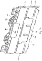
- Fig. 2a shows the transverse outer wall 16b in combination with the associated locking element 18b in an assembled representation
- Figure 2b represents the same outer wall in an exposure representation
- Figure 2c represents the outer wall 16b alone.
- the outer wall 16b and the locking element 18b is shown from the outside, while the Figure 2b and 2c to illustrate an inside view.
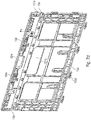
- Fig. 2d is also shows an interior view of the complete outer wall 16b together with a locking element 18b.
- the locking element 18a and 18b which forms the essential part of the locking mechanism, extends over the entire width of the transverse outer wall 16b.
- the locking element 18b has engagement areas or locking elements 19b. These can be formed, for example, by a projection or an extension of the locking element 18b.
- the two latching elements 19b have a recess so that they can snap into the associated latching hooks (not shown) on the longitudinal outer wall via this recess.
- the locking element 18b In order to release the locking state (the state in which the elements 19b are in engagement with the latching hooks / latching lugs of the longitudinal outer walls) and to form the release state, the locking element 18b is, as already explained at the beginning, designed to be displaceable. This displaceability is ensured by the grooves 16bn (cf. Figure 2b , 2c and 2d ) guided. These grooves extend along the direction F, that is to say, if one starts with an opened box, in the vertical direction away from the floor. This then guides the relative movement between element 18b and element 16b.
- the locking element 18b has an engagement area 18be on the inside, via which the locking element can be actuated.
- This engagement area 18be is designed, for example, as a recess, so that it can be reached with fingers in order to pull the locking element 18b in the direction F and thus transfer it from the locking state to the release state.
- the outer wall 16b has a handle 16bg which makes it possible to grip the box 10 in the opened state.
- This 16ge handle is how out Figure 2c is shown, formed directly in the element 16b and by means of a projection 16bv provided so that this projection 16bv (cf. Fig. 2a ) extends along the locking element 18b and protrudes over it or is at least of the same thickness, so that when gripping there is no accidental displacement of the locking element 18b (for example in direction F) and thus accidental actuation of the locking mechanism.
- the locking element 18b can have a recess 18ba for the handle 16bg.
- the transverse outer wall 16b on the hinge side (cf. reference number 17b) comprises hinge pins 16bb which, in combination with grooves (not shown) in the base plate (not shown), form the hinge 17b.
- the transverse outer wall has a so-called “overlap area" 16bu, in which the transverse outer wall 16b in the unfolded state rests against the respective longitudinal outer wall 14b so that the transverse outer wall 16b is prevented from moving further outwards (against the direction K) to fold out.
- overlap area 16bu in which the transverse outer wall 16b in the unfolded state rests against the respective longitudinal outer wall 14b so that the transverse outer wall 16b is prevented from moving further outwards (against the direction K) to fold out.
- the longitudinal outer wall 14a or 14b have a projection 14bv or 14av, which extends at the end of the longitudinal outer wall 14a or 14b in the direction of the transverse outer wall.
- a mortise cf. 16bv
- the projection 16bv or 14bv in combination with the overlap area enables the movement of the side wall 16b to be limited in the viewing direction of the hinge, while the mortise 16bv together with the grooves restricts the movement of the longitudinal outer walls 14a, 14b.
- such a tenon element can also be integrated into the locking element 18b.
- This tenon element is identified with the reference symbol 18bv and primarily fulfills a function comparable to that of the tenon element 16bv.
- the hook element 18bv as shown here, also have a hook shape, so that it engages in the longitudinal side wall 14a and 14b, or to be more precise, in the projections of the same 14av and 14bv in addition to the latching area 19b.
- the hook is shaped such that it enables engagement in the locked state and at least allows the side wall 16b to move in direction K in the released state.
- the locking state can be the state of the locking element 18a / 18b opposite the transverse outer wall 16a and 16b, the locked state of the four outer walls 14a , 14b, 16a and 16b in the unfolded state of the box 10 and is usually formed when the foldable box 10 is folded.
- the release state is actually always the state which the locking element 18a or 18b assumes with respect to the transverse outer wall 16a and 16b when engaging or for engaging and when releasing or for releasing. In this release state, the latching elements 19a and 19b are not in engagement with the associated latching lugs 14an and 14bn.
- FIG. 3d shows a longitudinal outer wall together with a transverse outer wall which are not in engagement.
- Fig. 3a shows the locking hook or the locking lug 14bn, which is connected to the locking element 19b (behind the locking lug or see Fig. 2a and 2d or 3b ) is engaged.
- the locking lug 14bn is arranged on the inside of the projection 14bv of the longitudinal outer wall 14b and thus extends at the end of the side wall 14b in the direction of the transverse outer wall 16b. This will also be done again with regard to Fig. 3d clearly, which shows the locking lug 14 on the projection 14av belonging to the longitudinal side wall 14a.
- the latching lug 14an (also the latching lug 14bn) is shaped in such a way that it has an undercut 14anh into which the latching element 19b can latch in the locked state.
- the locking element 19b belongs to the locking element 18b, as well as from Figure 3b emerges.
- the latching lug 14an or the latching lug 14bn is equipped with a beveled surface 14anf or 14bnf, so that the locking element 18b when moving outward (see arrow -K) in Figure 3b ) is moved from the locking state to the release state in order to then snap into the undercut 14anh.
- this locking is supported by a spring mechanism 16bf, which can be part of the side wall 16b, for example.
- the Figure 3b and 2c which shows this spring mechanism 16bf.
- the spring mechanism is implemented here as an elastically deforming bending beam.
- the spring element is preferably integrated into the side wall, which offers advantages in terms of manufacture and assembly.
- the spring element can also be formed by a separate spring or as part of the locking element 18b.
- the spring mechanism 16bf is designed to move the locking element into the locking position or to hold it in the locking position.
- the spring mechanism can optionally be designed in such a way that a constant preload prevails both in the release position and in the locking position.
- the groove 16bn can have one or more stops 16bna which prevent further movement in the direction F when the locking element 18b reaches the end position of the transverse outer wall 16b.
- an end position in the opposite direction can also be formed within these grooves 16bn.
- the locking element 18b rests on the free end 16be of the outer wall 16b. This version is in Figure 3c shown.
- Figure 3c shows the locking element 18b in a sectional view, the profile of the locking element 18b showing that the profile is angled so that the locking element 18b extends on the one hand parallel to the transverse outer wall 16b, namely on the outside and also a projection which extends beyond the free end 16b.
- This projection is identified with the reference symbol 18bp1
- the area extending on the outside of the outer wall 16b is identified with the reference symbol 18bp2. Due to the projection 18bp1, the locking element 18b can rest on the outer wall 16b and in particular on the free end of the outer wall 16be in the locked state.
- the outer wall 16b is then made shorter if the same compared with the outer wall 14a or 14b, so that the locking element 18b and in particular the area 18bp1 terminates together with the edge 14ar or 14br.
- the free spaces between the individual battens can also be roughly the same width in order to reproduce a uniform image of a battens.
- this statement relates primarily to the locking state.
- the box 10 can have not only the handles 16bg or 16ag on the transverse outer walls 16b and 16a, but also handles on the longitudinal outer walls.
- box 10 e.g. B.
- box 10 can be designed by an increased hinge area 15a and 15b in the bottom 12 so that the longitudinal outer walls 14a and 14b can be folded onto the transverse outer walls 16a and 16b. This affects the height of the individual parts.
- the locking element 18a / 18b is made in one piece, i.e. a cross strut with integrated locking elements 19a / 19b.
- the locking element 18a / 18b can also be made in several parts, e.g. as a profile produced by means of a sandwich construction (L or U shape).
Landscapes
- Engineering & Computer Science (AREA)
- Mechanical Engineering (AREA)
- Rigid Containers With Two Or More Constituent Elements (AREA)
Claims (15)
- Boîte pliable (10) avec un bord, aux caractéristiques suivantes:un fond (12); etchaque fois deux parois extérieures longitudinales et transversales (14a, 14b; 16a, 16b) opposées par paire, rabattables par rapport au fond (12), etdeux éléments de verrouillage (18a, 18b) avec une zone de bord intégrée;dans laquelle les parois extérieures longitudinales et transversales (14a, 14b; 16a, 16b) présentent, chacune, une charnière (15a, 15b; 17a, 17b) et une extrémité libre opposée à la charnière (15a, 15b; 17a, 17b), dans laquelle les deux parois extérieures longitudinales (14a, 14bb) forment, chacune, une zone de bord (14ar, 14br) le long de l'extrémité libre;dans laquelle les deux éléments de verrouillage (18a, 18b) sont disposés aux extrémités libres des parois extérieures transversales (16a, 16b) de sorte que les zones de bord intégrées des deux éléments de verrouillage (18a, 18b) et les deux zones de bord (14ar, 14br) des parois extérieures longitudinales (14a, 14b) forment le bord à l'état redressé de la boîte pliable;dans laquelle les deux éléments de verrouillage (18a, 18b) sont montés de manière mobile par rapport aux parois extérieures transversales (16a, 16b) pour former un mécanisme de verrouillage,caractérisée par le fait que les deux éléments de verrouillage (18a, 18b) peuvent être transférés par un mouvement dans une direction (F) s'éloignant du fond d'un état de verrouillage respectif à un état de dégagement.
- Boîte pliable (10) selon la revendication 1, dans laquelle les deux éléments de verrouillage (18a, 18b) viennent en prise par-dessus l'extrémité libre respective de la paroi extérieure transversale (16a, 16b).
- Boîte pliable (10) selon l'une des revendications précédentes, dans laquelle les deux éléments de verrouillage (18a, 18b) sont réalisés au moins par zones de manière coudée en coupe transversale et reposent sur l'extrémité libre respective des parois extérieures transversales (16a, 16b).
- Boîte pliable (10) selon l'une des revendications précédentes, dans laquelle les deux éléments de verrouillage (18a, 18b) présentent, au moins par zones, un profil en "L"; ou
dans laquelle les deux éléments de verrouillage (18a, 18b) présentent, au moins par zones, un profil en "U". - Boîte pliable (10) selon l'une des revendications précédentes, dans laquelle le mouvement des deux éléments de verrouillage (18a, 18b) s'étend, lors du transfert de l'état de verrouillage respectif à l'état de dégagement à l'état redressé, dans une direction verticale (F) par rapport à la surface du fond (12).
- Boîte pliable (10) selon la revendication 5, dans laquelle les deux éléments de verrouillage (18a, 18b) sont montés au moyen d'un mécanisme à ressort respectif (16bf) par rapport aux parois extérieures transversales (16a, 16b), dans laquelle le mécanisme à ressort (16bf) est conçu pour déplacer et/ou pour maintenir l'élément de verrouillage au moyen de la force de ressort du mécanisme à ressort (16bf) à l'état de verrouillage; ou
dans laquelle les deux éléments de verrouillage (18a, 18b) sont montés au moyen d'un mécanisme à ressort respectif (16bf) par rapport aux parois extérieures transversales (16a, 16b), dans laquelle le mécanisme à ressort (16bf) est conçu pour déplacer et/ou pour maintenir l'élément de verrouillage au moyen de la force de ressort du mécanisme à ressort (16bf) à l'état de verrouillage et dans laquelle le mécanisme à ressort respectif (16bf) est réalisé sous forme de ressort intégré dans la paroi extérieure transversale (16a, 16b). - Boîte pliable (10) selon l'une des revendications précédentes, dans laquelle les deux éléments de verrouillage (18a, 18b) sont réalisés d'une seule pièce et s'étendent sur toute la largeur de la paroi extérieure transversale.
- Boîte pliable (10) selon l'une des revendications précédentes, dans laquelle les parois extérieures longitudinales et transversales opposées (16a, 16b) simulent un lattage et/ou un lattage de bois qui s'étend le long de l'extrémité libre; et/ou
dans laquelle les deux éléments de verrouillage (18a, 18b) des parois extérieures transversales (16a, 16b) simulent, chacun, une latte du lattage ou du lattage en bois; et/ou
dans laquelle les deux zones de bord (14ar, 14br) des parois extérieures longitudinales (14a, 14b) simulent, chacune, une latte du lattage ou du lattage en bois; et/ou
dans laquelle les lattes qui sont formées par les deux éléments de verrouillage (18a, 18b) ainsi que les deux lattes qui sont formées par les deux zones de bord (14ar, 14br) présentent une hauteur sensiblement identique. - Boîte pliable (10) selon l'une des revendications précédentes, dans laquelle chacune des parois extérieures longitudinales (14a, 14b) présente, à au moins une extrémité transversale, une saillie (14av, 14bv) s'étendant, à l'état redressé, en direction des parois extérieures transversales (16a, 16b), laquelle limite l'aptitude des parois extérieures transversales à se replier vers l'extérieur; et/ou dans laquelle chacune des parois extérieures longitudinales (14a, 14b) présente, à au moins une extrémité transversale, un crochet d'encliquetage (14bn, 14an) s'étendant en direction des parois extérieures transversales (16a, 16b); et/ou
dans laquelle les deux éléments de verrouillage (18a, 18b) présentent, chacun, au moins un élément d'encliquetage (19a, 19b) s'étendant, à l'état redressé, en direction des parois extérieures longitudinales (14a, 14b); et/ou
dans laquelle l'au moins un élément de verrouillage (19a, 19b) est conçu pour être amené en prise avec l'au moins un crochet d'encliquetage (14bn, 14an) pour constituer l'état de verrouillage. - Boîte pliable (10) selon la revendication 9, dans laquelle le crochet d'encliquetage (14bn, 14an) présente une première surface de contact orientée vers l'intérieur (14bnf) qui est coudée de sorte que l'élément d'encliquetage (19a, 19b) transfère, lors du mouvement de la paroi extérieure transversale vers l'extérieur, l'élément d'encliquetage d'un état de verrouillage à un état de dégagement pour encliqueter le crochet d'encliquetage (14bn, 14an).
- Boîte pliable (10) selon la revendication 9 ou 10, dans laquelle les deux éléments de verrouillage (18a, 18b) sont montés et/ou prétendus de manière élastique par rapport aux parois extérieures transversales (16a, 16b) au moyen d'un mécanisme à ressort respectif (16bf) de sorte que le mouvement de l'état de verrouillage à l'état de dégagement ait lieu à l'encontre de la force de ressort.
- Boîte pliable (10) selon l'une des revendications précédentes, dans laquelle chaque paroi extérieure transversale présente une ou plusieurs rainures de guidage (16bn) s'étendant, à l'état redressé, verticalement le long de la paroi extérieure transversale, dans laquelle est guidé l'élément de verrouillage respectif lors de son déplacement par rapport à la paroi extérieure transversale; et/ou dans laquelle, dans au moins une des rainures de guidage (16bn) sont prévues une ou plusieurs butées d'extrémité (16bna) qui limitent le mouvement des éléments de verrouillage (18a, 18b) dans la direction verticale dans une ou plusieurs positions finales, et/ou dans laquelle les parois extérieures longitudinales (14a, 14b) s'étendent, dans une direction verticale (F) par rapport à la surface du fond (12), sur une plus grande hauteur que les parois extérieures transversales (16a, 16b).
- Boîte pliable (10) selon l'une des revendications précédentes, dans laquelle chacun des éléments de verrouillage (18a, 18b) présente une zone de prise (18be) pouvant être actionnée manuellement, par laquelle peut être actionné le mécanisme de verrouillage, dans laquelle la zone de prise pouvant être actionnée manuellement (18be) est formée sous forme d'évidement situé à l'intérieur ou de saillie située à l'intérieur (14av, 14bv).
- Boîte pliable (10) selon l'une des revendications précédentes, dans laquelle l'élément de verrouillage respectif (18a, 18b) est réalisé d'une seule pièce.
- Boîte pliable (10) selon l'une des revendications précédentes, dans laquelle chacune des parois extérieures transversales (16a, 16b) présente une poignée (16bg, 16ag) qui comporte une saillie (14av, 14bv) qui s'étend le long de l'élément de verrouillage associé (18a, 18b).
Priority Applications (1)
| Application Number | Priority Date | Filing Date | Title |
|---|---|---|---|
| PL18714971T PL3448768T3 (pl) | 2017-03-28 | 2018-03-27 | Skrzynka ze składalnymi ściankami bocznymi i mechanizmem blokowania w krawędzi |
Applications Claiming Priority (2)
| Application Number | Priority Date | Filing Date | Title |
|---|---|---|---|
| EP17163354.8A EP3381825A1 (fr) | 2017-03-28 | 2017-03-28 | Boîte ayant des parois latérales pliables et un mécanisme de verrouillage sur le bord |
| PCT/EP2018/000123 WO2018177591A1 (fr) | 2017-03-28 | 2018-03-27 | Caisse dotée de parois latérales pliables et mécanisme de verrouillage présent dans le bord |
Publications (2)
| Publication Number | Publication Date |
|---|---|
| EP3448768A1 EP3448768A1 (fr) | 2019-03-06 |
| EP3448768B1 true EP3448768B1 (fr) | 2020-11-04 |
Family
ID=58448468
Family Applications (2)
| Application Number | Title | Priority Date | Filing Date |
|---|---|---|---|
| EP17163354.8A Withdrawn EP3381825A1 (fr) | 2017-03-28 | 2017-03-28 | Boîte ayant des parois latérales pliables et un mécanisme de verrouillage sur le bord |
| EP18714971.1A Active EP3448768B1 (fr) | 2017-03-28 | 2018-03-27 | Boîte ayant des parois latérales pliables et un mécanisme de verrouillage sur le bord |
Family Applications Before (1)
| Application Number | Title | Priority Date | Filing Date |
|---|---|---|---|
| EP17163354.8A Withdrawn EP3381825A1 (fr) | 2017-03-28 | 2017-03-28 | Boîte ayant des parois latérales pliables et un mécanisme de verrouillage sur le bord |
Country Status (8)
| Country | Link |
|---|---|
| US (1) | US11091291B2 (fr) |
| EP (2) | EP3381825A1 (fr) |
| DK (1) | DK3448768T3 (fr) |
| ES (1) | ES2848073T3 (fr) |
| HU (1) | HUE053435T2 (fr) |
| PL (1) | PL3448768T3 (fr) |
| PT (1) | PT3448768T (fr) |
| WO (1) | WO2018177591A1 (fr) |
Families Citing this family (3)
| Publication number | Priority date | Publication date | Assignee | Title |
|---|---|---|---|---|
| AT522582B1 (de) | 2019-05-19 | 2020-12-15 | Hackl Gerhard | Behälter und Verfahren zur Herstellung eines Behälters |
| US12185857B2 (en) * | 2021-05-18 | 2025-01-07 | Ruben Salcedo, JR. | Self-contained removable and collapsible apparatus for the secure delivery and storage of parcels |
| IL289873B2 (en) * | 2022-01-16 | 2025-09-01 | Keter Home & Garden Products Ltd | Folding crate |
Citations (1)
| Publication number | Priority date | Publication date | Assignee | Title |
|---|---|---|---|---|
| WO2016112866A1 (fr) * | 2015-01-16 | 2016-07-21 | 上海鸿研物流技术有限公司 | Boîte pliante |
Family Cites Families (18)
| Publication number | Priority date | Publication date | Assignee | Title |
|---|---|---|---|---|
| US4960223A (en) * | 1989-07-18 | 1990-10-02 | Chiang Pei Lieh | Box crate container |
| US5501354A (en) * | 1992-05-26 | 1996-03-26 | Stromberg; Per S. | Collapsible container |
| DE19605080B4 (de) * | 1996-02-12 | 2007-05-03 | Ifco Systems Gmbh | Transportbehälter mit lösbar verrastbaren Klappwänden |
| US6015056A (en) * | 1997-12-19 | 2000-01-18 | Rehrig Pacific Company | Collapsible container |
| US6293418B1 (en) | 1999-12-09 | 2001-09-25 | Norseman Plastics Limited | Collapsible container |
| DE10200070B4 (de) * | 2002-01-03 | 2012-03-22 | Schoeller Arca Systems Gmbh | Klappbehälter mit einem Behälterboden und vier klappbaren Seitenwänden |
| US7059489B2 (en) * | 2002-10-11 | 2006-06-13 | Rehrig Pacific Company | Portable storage device |
| ES2306558B1 (es) * | 2005-12-27 | 2009-07-14 | Sp Berner Plastic Group, S.L. | Dispositivo de anclaje para cajas plegables. |
| DE102006041044A1 (de) * | 2006-09-01 | 2008-03-06 | Schoeller Arca Systems Services Gmbh | Transportbehälter |
| US7641066B2 (en) * | 2007-06-11 | 2010-01-05 | Rehrig Pacific Company | Collapsible container |
| JP4997002B2 (ja) * | 2007-07-11 | 2012-08-08 | 三甲株式会社 | 折り畳みコンテナー |
| JP5088649B2 (ja) * | 2007-07-18 | 2012-12-05 | 株式会社明治ゴム化成 | 組立式合成樹脂製容器 |
| IL186787A0 (en) | 2007-10-18 | 2008-02-09 | Polymer Logistics Ltd | Foldable crate with bidirectional manually releasable latch mechanism |
| DE202008005791U1 (de) | 2008-04-25 | 2008-08-28 | Bekuplast Kunststoffverarbeitungs-Gmbh | Transport- und Lagerbehälter mit Riegeleinrichtung |
| EP2296988B1 (fr) * | 2008-06-17 | 2013-03-20 | Georg Utz Holding AG | Caisse de transport et d'entreposage pliante |
| DE202010000856U1 (de) * | 2010-01-13 | 2010-04-08 | Schoeller Arca Systems Gmbh | Großladungsträger |
| US8381929B2 (en) * | 2010-04-27 | 2013-02-26 | Ifco Systems Gmbh | Container with side walls foldable on top of one another |
| DE202011102591U1 (de) | 2011-06-30 | 2012-10-01 | Bekuplast Kunststoffverarbeitungs-Gmbh | Klappbehälter |
-
2017
- 2017-03-28 EP EP17163354.8A patent/EP3381825A1/fr not_active Withdrawn
-
2018
- 2018-03-27 DK DK18714971.1T patent/DK3448768T3/da active
- 2018-03-27 PT PT187149711T patent/PT3448768T/pt unknown
- 2018-03-27 HU HUE18714971A patent/HUE053435T2/hu unknown
- 2018-03-27 ES ES18714971T patent/ES2848073T3/es active Active
- 2018-03-27 EP EP18714971.1A patent/EP3448768B1/fr active Active
- 2018-03-27 PL PL18714971T patent/PL3448768T3/pl unknown
- 2018-03-27 WO PCT/EP2018/000123 patent/WO2018177591A1/fr not_active Ceased
-
2019
- 2019-09-27 US US16/586,065 patent/US11091291B2/en active Active
Patent Citations (1)
| Publication number | Priority date | Publication date | Assignee | Title |
|---|---|---|---|---|
| WO2016112866A1 (fr) * | 2015-01-16 | 2016-07-21 | 上海鸿研物流技术有限公司 | Boîte pliante |
Also Published As
| Publication number | Publication date |
|---|---|
| DK3448768T3 (da) | 2021-02-08 |
| US11091291B2 (en) | 2021-08-17 |
| WO2018177591A1 (fr) | 2018-10-04 |
| PT3448768T (pt) | 2021-02-04 |
| ES2848073T3 (es) | 2021-08-05 |
| PL3448768T3 (pl) | 2021-05-31 |
| US20200024030A1 (en) | 2020-01-23 |
| HUE053435T2 (hu) | 2021-06-28 |
| EP3448768A1 (fr) | 2019-03-06 |
| EP3381825A1 (fr) | 2018-10-03 |
Similar Documents
| Publication | Publication Date | Title |
|---|---|---|
| DE19605080B4 (de) | Transportbehälter mit lösbar verrastbaren Klappwänden | |
| DE2312871A1 (de) | Kiste | |
| EP2288765A2 (fr) | Structure porteuse en treillis | |
| EP2477902A1 (fr) | Caisse utilisable de manière flexible | |
| DE3500427A1 (de) | Zusammenklappbarer transportkasten | |
| EP3587294B1 (fr) | Récipient empilable pourvu de mécanisme de raccordement | |
| DE2128507A1 (de) | Transport- und Vorratsbehälter für Gegenstände aller Art, insbesondere Warenpackungen | |
| AT506872B1 (de) | Verschlussriegel für transportbehälter mit klappbaren seitenwänden | |
| WO2009153693A1 (fr) | Caisse de transport et d'entreposage pliante | |
| DE202015102816U1 (de) | Zusammenklappbare Kiste und zugehörige Verriegelungsmechanismen | |
| EP2408677B1 (fr) | Réceptacle à paroi latérale repliable | |
| DE102009007358A1 (de) | Großladungsträger | |
| EP2673206B1 (fr) | Caisse | |
| DE9314298U1 (de) | Lager- und Transportkasten | |
| EP3448768A1 (fr) | Caisse dotée de parois latérales pliables et mécanisme de verrouillage présent dans le bord | |
| EP4059860A1 (fr) | Conteneur empilable pourvu de parois rabattables | |
| DE202019005423U1 (de) | Transportbehälter | |
| DE4408649A1 (de) | Zusammenlegbarer Lager- und Transportkasten | |
| DE3204645A1 (de) | Gitterboxpalette | |
| DE1301753B (de) | Zusammenlegbarer Kunststoffkasten | |
| DE69402345T2 (de) | Faltbarer Kunststoffkasten zum ordentlichen Transportieren und Lagern von Flaschen | |
| DE202011002551U1 (de) | Transport- und Lagerbehälter | |
| DE9305903U1 (de) | Zusammenlegbarer Lager- und Transportkasten | |
| CH405149A (de) | Stapelbarer Behälter | |
| DE202018106801U1 (de) | Verkaufstisch |
Legal Events
| Date | Code | Title | Description |
|---|---|---|---|
| STAA | Information on the status of an ep patent application or granted ep patent |
Free format text: STATUS: UNKNOWN |
|
| STAA | Information on the status of an ep patent application or granted ep patent |
Free format text: STATUS: THE INTERNATIONAL PUBLICATION HAS BEEN MADE |
|
| PUAI | Public reference made under article 153(3) epc to a published international application that has entered the european phase |
Free format text: ORIGINAL CODE: 0009012 |
|
| STAA | Information on the status of an ep patent application or granted ep patent |
Free format text: STATUS: REQUEST FOR EXAMINATION WAS MADE |
|
| 17P | Request for examination filed |
Effective date: 20181128 |
|
| AK | Designated contracting states |
Kind code of ref document: A1 Designated state(s): AL AT BE BG CH CY CZ DE DK EE ES FI FR GB GR HR HU IE IS IT LI LT LU LV MC MK MT NL NO PL PT RO RS SE SI SK SM TR |
|
| AX | Request for extension of the european patent |
Extension state: BA ME |
|
| GRAP | Despatch of communication of intention to grant a patent |
Free format text: ORIGINAL CODE: EPIDOSNIGR1 |
|
| STAA | Information on the status of an ep patent application or granted ep patent |
Free format text: STATUS: GRANT OF PATENT IS INTENDED |
|
| DAV | Request for validation of the european patent (deleted) | ||
| DAX | Request for extension of the european patent (deleted) | ||
| INTG | Intention to grant announced |
Effective date: 20191202 |
|
| GRAS | Grant fee paid |
Free format text: ORIGINAL CODE: EPIDOSNIGR3 |
|
| GRAA | (expected) grant |
Free format text: ORIGINAL CODE: 0009210 |
|
| STAA | Information on the status of an ep patent application or granted ep patent |
Free format text: STATUS: THE PATENT HAS BEEN GRANTED |
|
| AK | Designated contracting states |
Kind code of ref document: B1 Designated state(s): AL AT BE BG CH CY CZ DE DK EE ES FI FR GB GR HR HU IE IS IT LI LT LU LV MC MK MT NL NO PL PT RO RS SE SI SK SM TR |
|
| REG | Reference to a national code |
Ref country code: GB Ref legal event code: FG4D Free format text: NOT ENGLISH |
|
| REG | Reference to a national code |
Ref country code: CH Ref legal event code: EP |
|
| REG | Reference to a national code |
Ref country code: AT Ref legal event code: REF Ref document number: 1330547 Country of ref document: AT Kind code of ref document: T Effective date: 20201115 |
|
| REG | Reference to a national code |
Ref country code: DE Ref legal event code: R096 Ref document number: 502018002932 Country of ref document: DE |
|
| REG | Reference to a national code |
Ref country code: IE Ref legal event code: FG4D Free format text: LANGUAGE OF EP DOCUMENT: GERMAN |
|
| REG | Reference to a national code |
Ref country code: RO Ref legal event code: EPE |
|
| REG | Reference to a national code |
Ref country code: PT Ref legal event code: SC4A Ref document number: 3448768 Country of ref document: PT Date of ref document: 20210204 Kind code of ref document: T Free format text: AVAILABILITY OF NATIONAL TRANSLATION Effective date: 20210127 |
|
| REG | Reference to a national code |
Ref country code: DK Ref legal event code: T3 Effective date: 20210202 |
|
| REG | Reference to a national code |
Ref country code: CH Ref legal event code: NV Representative=s name: BOVARD AG PATENT- UND MARKENANWAELTE, CH |
|
| REG | Reference to a national code |
Ref country code: NL Ref legal event code: FP |
|
| REG | Reference to a national code |
Ref country code: SE Ref legal event code: TRGR |
|
| REG | Reference to a national code |
Ref country code: SK Ref legal event code: T3 Ref document number: E 36376 Country of ref document: SK |
|
| REG | Reference to a national code |
Ref country code: GR Ref legal event code: EP Ref document number: 20210400273 Country of ref document: GR Effective date: 20210316 |
|
| REG | Reference to a national code |
Ref country code: NO Ref legal event code: T2 Effective date: 20201104 |
|
| PG25 | Lapsed in a contracting state [announced via postgrant information from national office to epo] |
Ref country code: RS Free format text: LAPSE BECAUSE OF FAILURE TO SUBMIT A TRANSLATION OF THE DESCRIPTION OR TO PAY THE FEE WITHIN THE PRESCRIBED TIME-LIMIT Effective date: 20201104 Ref country code: FI Free format text: LAPSE BECAUSE OF FAILURE TO SUBMIT A TRANSLATION OF THE DESCRIPTION OR TO PAY THE FEE WITHIN THE PRESCRIBED TIME-LIMIT Effective date: 20201104 |
|
| PG25 | Lapsed in a contracting state [announced via postgrant information from national office to epo] |
Ref country code: IS Free format text: LAPSE BECAUSE OF FAILURE TO SUBMIT A TRANSLATION OF THE DESCRIPTION OR TO PAY THE FEE WITHIN THE PRESCRIBED TIME-LIMIT Effective date: 20210304 Ref country code: LV Free format text: LAPSE BECAUSE OF FAILURE TO SUBMIT A TRANSLATION OF THE DESCRIPTION OR TO PAY THE FEE WITHIN THE PRESCRIBED TIME-LIMIT Effective date: 20201104 Ref country code: BG Free format text: LAPSE BECAUSE OF FAILURE TO SUBMIT A TRANSLATION OF THE DESCRIPTION OR TO PAY THE FEE WITHIN THE PRESCRIBED TIME-LIMIT Effective date: 20210204 |
|
| REG | Reference to a national code |
Ref country code: LT Ref legal event code: MG9D |
|
| REG | Reference to a national code |
Ref country code: HU Ref legal event code: AG4A Ref document number: E053435 Country of ref document: HU |
|
| PG25 | Lapsed in a contracting state [announced via postgrant information from national office to epo] |
Ref country code: HR Free format text: LAPSE BECAUSE OF FAILURE TO SUBMIT A TRANSLATION OF THE DESCRIPTION OR TO PAY THE FEE WITHIN THE PRESCRIBED TIME-LIMIT Effective date: 20201104 |
|
| PG25 | Lapsed in a contracting state [announced via postgrant information from national office to epo] |
Ref country code: LT Free format text: LAPSE BECAUSE OF FAILURE TO SUBMIT A TRANSLATION OF THE DESCRIPTION OR TO PAY THE FEE WITHIN THE PRESCRIBED TIME-LIMIT Effective date: 20201104 Ref country code: EE Free format text: LAPSE BECAUSE OF FAILURE TO SUBMIT A TRANSLATION OF THE DESCRIPTION OR TO PAY THE FEE WITHIN THE PRESCRIBED TIME-LIMIT Effective date: 20201104 Ref country code: SM Free format text: LAPSE BECAUSE OF FAILURE TO SUBMIT A TRANSLATION OF THE DESCRIPTION OR TO PAY THE FEE WITHIN THE PRESCRIBED TIME-LIMIT Effective date: 20201104 |
|
| REG | Reference to a national code |
Ref country code: DE Ref legal event code: R097 Ref document number: 502018002932 Country of ref document: DE Ref country code: ES Ref legal event code: FG2A Ref document number: 2848073 Country of ref document: ES Kind code of ref document: T3 Effective date: 20210805 |
|
| PLBE | No opposition filed within time limit |
Free format text: ORIGINAL CODE: 0009261 |
|
| STAA | Information on the status of an ep patent application or granted ep patent |
Free format text: STATUS: NO OPPOSITION FILED WITHIN TIME LIMIT |
|
| 26N | No opposition filed |
Effective date: 20210805 |
|
| PG25 | Lapsed in a contracting state [announced via postgrant information from national office to epo] |
Ref country code: MC Free format text: LAPSE BECAUSE OF FAILURE TO SUBMIT A TRANSLATION OF THE DESCRIPTION OR TO PAY THE FEE WITHIN THE PRESCRIBED TIME-LIMIT Effective date: 20201104 Ref country code: AL Free format text: LAPSE BECAUSE OF FAILURE TO SUBMIT A TRANSLATION OF THE DESCRIPTION OR TO PAY THE FEE WITHIN THE PRESCRIBED TIME-LIMIT Effective date: 20201104 |
|
| PG25 | Lapsed in a contracting state [announced via postgrant information from national office to epo] |
Ref country code: SI Free format text: LAPSE BECAUSE OF FAILURE TO SUBMIT A TRANSLATION OF THE DESCRIPTION OR TO PAY THE FEE WITHIN THE PRESCRIBED TIME-LIMIT Effective date: 20201104 |
|
| PG25 | Lapsed in a contracting state [announced via postgrant information from national office to epo] |
Ref country code: IE Free format text: LAPSE BECAUSE OF NON-PAYMENT OF DUE FEES Effective date: 20210327 Ref country code: LU Free format text: LAPSE BECAUSE OF NON-PAYMENT OF DUE FEES Effective date: 20210327 |
|
| PG25 | Lapsed in a contracting state [announced via postgrant information from national office to epo] |
Ref country code: IS Free format text: LAPSE BECAUSE OF FAILURE TO SUBMIT A TRANSLATION OF THE DESCRIPTION OR TO PAY THE FEE WITHIN THE PRESCRIBED TIME-LIMIT Effective date: 20210304 |
|
| PG25 | Lapsed in a contracting state [announced via postgrant information from national office to epo] |
Ref country code: CY Free format text: LAPSE BECAUSE OF FAILURE TO SUBMIT A TRANSLATION OF THE DESCRIPTION OR TO PAY THE FEE WITHIN THE PRESCRIBED TIME-LIMIT Effective date: 20201104 |
|
| PG25 | Lapsed in a contracting state [announced via postgrant information from national office to epo] |
Ref country code: MK Free format text: LAPSE BECAUSE OF FAILURE TO SUBMIT A TRANSLATION OF THE DESCRIPTION OR TO PAY THE FEE WITHIN THE PRESCRIBED TIME-LIMIT Effective date: 20201104 |
|
| PG25 | Lapsed in a contracting state [announced via postgrant information from national office to epo] |
Ref country code: MT Free format text: LAPSE BECAUSE OF FAILURE TO SUBMIT A TRANSLATION OF THE DESCRIPTION OR TO PAY THE FEE WITHIN THE PRESCRIBED TIME-LIMIT Effective date: 20201104 |
|
| PGFP | Annual fee paid to national office [announced via postgrant information from national office to epo] |
Ref country code: ES Payment date: 20250414 Year of fee payment: 8 |
|
| PGFP | Annual fee paid to national office [announced via postgrant information from national office to epo] |
Ref country code: CH Payment date: 20250401 Year of fee payment: 8 |
|
| PGFP | Annual fee paid to national office [announced via postgrant information from national office to epo] |
Ref country code: FR Payment date: 20251231 Year of fee payment: 9 |
|
| PGFP | Annual fee paid to national office [announced via postgrant information from national office to epo] |
Ref country code: NL Payment date: 20260106 Year of fee payment: 9 |
|
| REG | Reference to a national code |
Ref country code: CH Ref legal event code: U11 Free format text: ST27 STATUS EVENT CODE: U-0-0-U10-U11 (AS PROVIDED BY THE NATIONAL OFFICE) Effective date: 20260401 |
|
| PGFP | Annual fee paid to national office [announced via postgrant information from national office to epo] |
Ref country code: SE Payment date: 20260105 Year of fee payment: 9 |
|
| PGFP | Annual fee paid to national office [announced via postgrant information from national office to epo] |
Ref country code: GB Payment date: 20260106 Year of fee payment: 9 |
|
| PGFP | Annual fee paid to national office [announced via postgrant information from national office to epo] |
Ref country code: NO Payment date: 20260310 Year of fee payment: 9 Ref country code: DE Payment date: 20260102 Year of fee payment: 9 Ref country code: DK Payment date: 20260313 Year of fee payment: 9 |
|
| PGFP | Annual fee paid to national office [announced via postgrant information from national office to epo] |
Ref country code: AT Payment date: 20260225 Year of fee payment: 9 |
|
| PGFP | Annual fee paid to national office [announced via postgrant information from national office to epo] |
Ref country code: BE Payment date: 20260105 Year of fee payment: 9 Ref country code: RO Payment date: 20260213 Year of fee payment: 9 Ref country code: IT Payment date: 20260220 Year of fee payment: 9 |
|
| PGFP | Annual fee paid to national office [announced via postgrant information from national office to epo] |
Ref country code: HU Payment date: 20260303 Year of fee payment: 9 |
|
| PGFP | Annual fee paid to national office [announced via postgrant information from national office to epo] |
Ref country code: TR Payment date: 20260326 Year of fee payment: 9 |
|
| PGFP | Annual fee paid to national office [announced via postgrant information from national office to epo] |
Ref country code: PT Payment date: 20260324 Year of fee payment: 9 Ref country code: CZ Payment date: 20260310 Year of fee payment: 9 |
|
| PGFP | Annual fee paid to national office [announced via postgrant information from national office to epo] |
Ref country code: GR Payment date: 20260211 Year of fee payment: 9 Ref country code: PL Payment date: 20260115 Year of fee payment: 9 |
|
| PGFP | Annual fee paid to national office [announced via postgrant information from national office to epo] |
Ref country code: SK Payment date: 20260212 Year of fee payment: 9 |