EP3449061B1 - Lame de préhension et de coupe munie d'une paroi d'extraction - Google Patents
Lame de préhension et de coupe munie d'une paroi d'extraction Download PDFInfo
- Publication number
- EP3449061B1 EP3449061B1 EP17743075.8A EP17743075A EP3449061B1 EP 3449061 B1 EP3449061 B1 EP 3449061B1 EP 17743075 A EP17743075 A EP 17743075A EP 3449061 B1 EP3449061 B1 EP 3449061B1
- Authority
- EP
- European Patent Office
- Prior art keywords
- shovel
- slide
- out wall
- gripping
- wall
- Prior art date
- Legal status (The legal status is an assumption and is not a legal conclusion. Google has not performed a legal analysis and makes no representation as to the accuracy of the status listed.)
- Active
Links
Images




Classifications
-
- E—FIXED CONSTRUCTIONS
- E02—HYDRAULIC ENGINEERING; FOUNDATIONS; SOIL SHIFTING
- E02F—DREDGING; SOIL-SHIFTING
- E02F3/00—Dredgers; Soil-shifting machines
- E02F3/04—Dredgers; Soil-shifting machines mechanically-driven
- E02F3/28—Dredgers; Soil-shifting machines mechanically-driven with digging tools mounted on a dipper- or bucket-arm, i.e. there is either one arm or a pair of arms, e.g. dippers, buckets
- E02F3/36—Component parts
- E02F3/40—Dippers; Buckets ; Grab devices, e.g. manufacturing processes for buckets, form, geometry or material of buckets
- E02F3/401—Buckets or forks comprising, for example, shock absorbers, supports or load striking scrapers to prevent overload
-
- B—PERFORMING OPERATIONS; TRANSPORTING
- B66—HOISTING; LIFTING; HAULING
- B66C—CRANES; LOAD-ENGAGING ELEMENTS OR DEVICES FOR CRANES, CAPSTANS, WINCHES, OR TACKLES
- B66C3/00—Load-engaging elements or devices attached to lifting or lowering gear of cranes or adapted for connection therewith and intended primarily for transmitting lifting forces to loose materials; Grabs
- B66C3/14—Grabs opened or closed by driving motors thereon
- B66C3/16—Grabs opened or closed by driving motors thereon by fluid motors
-
- E—FIXED CONSTRUCTIONS
- E02—HYDRAULIC ENGINEERING; FOUNDATIONS; SOIL SHIFTING
- E02F—DREDGING; SOIL-SHIFTING
- E02F3/00—Dredgers; Soil-shifting machines
- E02F3/04—Dredgers; Soil-shifting machines mechanically-driven
- E02F3/28—Dredgers; Soil-shifting machines mechanically-driven with digging tools mounted on a dipper- or bucket-arm, i.e. there is either one arm or a pair of arms, e.g. dippers, buckets
- E02F3/36—Component parts
- E02F3/40—Dippers; Buckets ; Grab devices, e.g. manufacturing processes for buckets, form, geometry or material of buckets
- E02F3/402—Dippers; Buckets ; Grab devices, e.g. manufacturing processes for buckets, form, geometry or material of buckets with means for facilitating the loading thereof, e.g. conveyors
- E02F3/404—Dippers; Buckets ; Grab devices, e.g. manufacturing processes for buckets, form, geometry or material of buckets with means for facilitating the loading thereof, e.g. conveyors comprising two parts movable relative to each other, e.g. for gripping
-
- E—FIXED CONSTRUCTIONS
- E02—HYDRAULIC ENGINEERING; FOUNDATIONS; SOIL SHIFTING
- E02F—DREDGING; SOIL-SHIFTING
- E02F3/00—Dredgers; Soil-shifting machines
- E02F3/04—Dredgers; Soil-shifting machines mechanically-driven
- E02F3/28—Dredgers; Soil-shifting machines mechanically-driven with digging tools mounted on a dipper- or bucket-arm, i.e. there is either one arm or a pair of arms, e.g. dippers, buckets
- E02F3/36—Component parts
- E02F3/40—Dippers; Buckets ; Grab devices, e.g. manufacturing processes for buckets, form, geometry or material of buckets
- E02F3/407—Dippers; Buckets ; Grab devices, e.g. manufacturing processes for buckets, form, geometry or material of buckets with ejecting or other unloading device
-
- E—FIXED CONSTRUCTIONS
- E02—HYDRAULIC ENGINEERING; FOUNDATIONS; SOIL SHIFTING
- E02F—DREDGING; SOIL-SHIFTING
- E02F3/00—Dredgers; Soil-shifting machines
- E02F3/04—Dredgers; Soil-shifting machines mechanically-driven
- E02F3/28—Dredgers; Soil-shifting machines mechanically-driven with digging tools mounted on a dipper- or bucket-arm, i.e. there is either one arm or a pair of arms, e.g. dippers, buckets
- E02F3/36—Component parts
- E02F3/40—Dippers; Buckets ; Grab devices, e.g. manufacturing processes for buckets, form, geometry or material of buckets
- E02F3/413—Dippers; Buckets ; Grab devices, e.g. manufacturing processes for buckets, form, geometry or material of buckets with grabbing device
-
- E—FIXED CONSTRUCTIONS
- E02—HYDRAULIC ENGINEERING; FOUNDATIONS; SOIL SHIFTING
- E02F—DREDGING; SOIL-SHIFTING
- E02F3/00—Dredgers; Soil-shifting machines
- E02F3/04—Dredgers; Soil-shifting machines mechanically-driven
- E02F3/76—Graders, bulldozers, or the like with scraper plates or ploughshare-like elements; Levelling scarifying devices
- E02F3/80—Component parts
- E02F3/815—Blades; Levelling or scarifying tools
- E02F3/8155—Blades; Levelling or scarifying tools provided with movable parts, e.g. cutting discs, vibrating teeth or the like
Definitions
- the invention relates to a gripping and cutting shovel with a push-out wall according to the preamble of claim 1.
- a gripping and cutting shovel with a push-out wall according to the preamble of claim 1.
- Such a device is in US3211065A disclosed.
- the patent application relates to a loading shovel designed as a gripping or cutting shovel for attachment to carrier vehicles such as. E.g. wheel loaders, yard loaders, telehandlers and tractors. These devices are used, among other things, to remove feed from so-called flat silos in agriculture.
- Such gripping or cutting blades generally consist of a blade as a lower part and an upper part designed as a gripper, comb, cutting knife or milling drum, hereinafter referred to as a gripper.
- a gripper Normally, the gripper and the shovel are connected to one another via a pivot point or an axis of rotation.
- the gripper is moved by one or more hydraulic cylinders about a pivot point positioned on the bucket so that the opening of the bucket can be opened or closed.
- gripping buckets that have a push-out wall that is firmly connected to the gripper, which pushes the contents of the shovel forward out of the shovel when the gripper is opened. With these gripping blades, the gripper and the push-out wall are a rigid component whose angle to one another cannot be changed.
- the gripping or cutting shovel consists of a lower part designed as a shovel and an upper part preferably designed as a gripper and the shovel accommodates a movable rear wall and at least the upper part and the movable rear wall can be moved into different positions and the movable rear wall acts as a freely movable push-out wall is carried out, which is mounted on the axis of rotation of the gripper, or on a separate axis of rotation which is located at a different position than the axis of rotation of the gripper, and the relative position of the push-out wall and the upper part can be changed to one another, it is ensured that a blade structure is created which can be used flexibly and is protected against overload.
- a high degree of flexibility in the implementation of the movement sequences is achieved in an advantageous embodiment if the relative position of the push-out wall and the upper part to one another can be changed by means of separate drives or by means of a common drive, the push-out wall depending on the position of the upper part or independently of the position of the upper part can be moved.
- a further advantageous embodiment of the invention provides that the push-out wall only opens from a position of the gripper in which the gripper has released the shovel opening and depending on the position of the gripper is movable.
- a functionally reliable implementation of the coordinated movement sequences is achieved in an advantageous development of the invention when the change in the relative position of the push-out wall and the upper part to one another takes place by means of a cam track control and the shape of the cam track is picked up by one or more rollers from one or more cam track segments and the one or more cam track segments of the movable rear wall and the one or more rollers are each assigned to the upper part or vice versa.
- the gripping and cutting blade according to the invention is then reliably protected from damage if, in one embodiment, at least one overload protection device is assigned to the push-out wall and/or the drive(s).
- the movement sequences can be easily implemented if, in an advantageous embodiment of the invention, the separate drives are designed as lifting cylinders arranged in pairs, with each pair of lifting cylinders being pivotally articulated at one end to the lower part of the gripping and cutting blade and at the other end to the upper part or the push-out wall .
- a low-wear and safe implementation of the movement sequence stored in the cam track is achieved in an advantageous embodiment if the push-out wall has at least one lever arm to which at least one roller is attached, and the gripper has at least one cam track comprising a cam track segment, which when pivoting the Upper part acts on the at least one roller of the push-out wall in order to pivot the push-out wall.
- the cam track and roller are swapped in such a way that the push-out wall has at least one lever arm, to which at least one cam track comprising a cam track segment is attached, and the upper part has at least one roller which is used when the The upper part acts on the curved path of the push-out wall in order to pivot the push-out wall.
- the cam track control comprises at least one rocker, which has a bearing point in the middle area between the two ends via which the rocker is attached to the blade, the rocker receiving at one end at least one roller on which the upper part, or one on the upper part attached cam track acts when the upper part is pivoted and at the other end of the at least one rocker an articulation point accommodates a coupling rod with two articulation points, the at least one coupling rod being pivotally connected to its second articulation point on the push-out wall or on a lever arm connected to the push-out wall and the at least one coupling rod transfers the force and movement introduced from the upper part onto the rocker to the push-out wall in such a way that the push-out wall is pivoted, creating a solution that allows a simple curved track structure.
- cam track attached to the upper part, which acts on the roller on the rocker is shaped in such a way that the rocker and thus the push-out wall are immediately freely movable again after reaching the frontmost position and the gripper is in the top position.
- the common drive comprises lifting cylinders arranged in pairs and a coupling mechanism, the lifting cylinders arranged in pairs being pivotally connected at one end to the lower part of the gripping and cutting blade and at the other end to the upper part, and the coupling mechanism is connected at one end to the push-out wall designed as a movable rear wall and other end is connected to the top.
- the coupling mechanism includes a cam track control and/or an overload protection.
- the coupling mechanism can then coordinate the movement sequences with one another in a very functionally reliable manner if the cam track control comprises one or more cam track segments that accommodate the cam track and one or more rollers that grip the cam track, the cam track being assigned to the movable push-out wall and the one or more rollers to the upper part.
- the cam track control comprises one or more cam track segments that accommodate the cam track and one or more rollers that grip the cam track, the cam track being assigned to the movable push-out wall and the one or more rollers to the upper part.
- This effect is also increased if the curved track segment includes arcuate front and rear areas and the areas are separated from each other by a recess, with the roller being guided along the arcuate area and the recess.
- the arcuate shape of the rear arcuate segment having a radius that decreases from the beginning to the end of this arcuate segment, in an advantageous development of the invention it is ensured that the return movement of the push-out wall is supported when the roller is pressed onto the arcuate curved track under pretension.
- this is achieved in that at least one compression spring cylinder is assigned to the coupling mechanism in its lateral end regions, which connects the push-out blade and the gripper to one another in such a way that a change in the relative position of the gripper and blade to one another is possible.
- the overload protection results from an interaction of one or more of the lifting cylinders, compression spring cylinders and/or cam track segments assigned to the coupling mechanism.
- a space-saving design of the gripping and cutting blade results when the blade has side walls and a rear wall provided with stiffening struts and the lifting cylinders of the drive are positioned in a free space formed between the side walls and the stiffening struts.
- the bottom and the rear wall of the blade are designed with rectilinear and/or arcuate contours.
- the bottom of the shovel consists of at least one straight surface and the push-out wall consists of at least two elements which are connected horizontally by at least one hinge, the push-out wall being in the extended length when all elements are in lie in alignment and form a straight surface, is longer than the largest possible distance between the pivot point of the push-out wall and the blade base and wherein the push-out wall is preferably on the lower edge, which is in contact with the bottom of the blade, with at least one sliding element, preferably designed as a roller is provided.
- the push-out wall contains at least one extendable element through which the length of the push-out wall can be changed and whereby the Push-out wall with the push-out element, in particular on the lower edge, which has contact with the blade base, is provided with at least one sliding element, preferably designed as a roller.
- the implementation of the coordinated movement sequences can be implemented in a space-saving manner in that the actuation mechanism of the push-out wall has a transmission ratio that, with a small pivoting path of the upper part, moves the push-out wall from the rear wall of the blade to the front edge of the blade.
- Jamming of the push-out blade can be counteracted by the rear wall and/or the blade base having at least one opening through which the space between the push-out wall and the rear wall of the shovel is accessible, so that goods located in the rear area of the push-out wall can be easily removed .
- Contamination of the movement paths of the push-out wall can also be counteracted in that the push-out wall has a seal on one or more sides to the side walls and / or the bottom and / or the rear wall of the shovel and the seal preferably consists of an elastic material or consists of a rigid material and can be pressed against the walls and/or the blade base and/or the top of the blade opening by a spring force.
- the blade and/or the push-out wall can have a stop or a device which prevents the push-out wall from pivoting forward out of the blade, so that the movement of the push-out wall in the blade opening direction is reliably limited.
- the push-out wall can be locked in the rearmost position, on or near the rear wall of the shovel.
- Figure 1 shows schematically a carrier vehicle 1 designed as a telescopic loader 2, it being within the scope of the invention that the carrier vehicle 1 can also be designed as a wheel loader, farm loader, tractor or the like.
- the support structure 4, designed as a support frame 3 accommodates in a central position a telescopic lifting arm 5, to which a tool adapter 6, which is known per se, is assigned to the front.
- the lifting arm 5 is pivotally mounted in its rear area by at least one pivot axis 8 arranged in support flanges 7 transversely to the direction of travel FR and in order to realize the pivoting movement, one or more lifting cylinders 9 are assigned to the bottom of the lifting arm 5, which pivot the lifting arm by pressurizing or releasing pressure 5 about the said pivot axis 8 enable.
- the telescopic retraction and extension of the lifting arm 5 is realized in a manner known per se and therefore not shown in detail by means of additional lifting cylinders.
- the carrier vehicle 1 is in the area of Tool adapter 6 is assigned the gripping and cutting blade 10 according to the invention and to be described in more detail below.
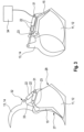
- FIG 2 shows schematically a first embodiment variant of the gripping and cutting blade 10 according to the invention.
- the gripping and cutting blade 10 consists of a lower part 12 designed as a blade 11 and an upper part 14 designed as a gripper 13 as well as the movable rear wall 16 according to the invention designed as a push-out wall 15.
- the gripper 13 and the push-out wall 15 are here pivotally connected to it by a common axis of rotation 17 received by the blade 11.
- the push-out wall 15 and the gripper 11 can also be attached to separate, independent rotation axes 17, which are also located in different positions.
- the gripper 13 and the push-out wall 15 carry out pivoting movements 18, 19 about the respective axis of rotation 17, the pivoting movements 18, 19 being such that the gripper 13 and the push-out wall 15 maintain their relative position 20 to one another can change.
- the drives 21 can be used as in Figure 1 only schematically indicated lifting cylinders 22 can be designed.
- the push-out wall 15 is moved by a lever arm 23 which is operatively connected to the respective lifting cylinder 22 and which at one end accommodates a freely rotatable roller 24 which acts on a cam track 26 picked up by a cam track segment 25 positioned on the gripper 13 or pushes it when the gripper 13 pushes through a drive 21, preferably a lifting cylinder 22, is pivoted upwards and the blade opening 27 has already been released. If the gripper 13 is now moved further upwards, the cam track 26 presses the rollers 24 with the lever arm 23 around the axis of rotation 17, which then pivots the push-out wall 15 into the frontmost position in the direction of the shovel opening 27, so that the load moves forward out of the shovel 11 is pushed out.
- This process can be controlled and metered very well by the movement of the gripper 13.
- the roller 24 no longer has contact with the cam track 26 and releases the lever arm 23 so that the push-off wall 15 can move freely on the axis of rotation 17 and it can be pushed back from the load to a rear wall 28 assigned to the shovel 11 in the rear area.
- At least one stop 29 can prevent the push-out wall 15 from pivoting forward out of the blade opening 27, whereby the stop 29 can be designed in such a way that it acts directly on the push-out wall 15 and limits its path and/or the path of the push-out wall 15 Lever arm 23 of the push-out wall 15 limited.
- the push-out wall 15 it becomes possible for the push-out wall 15 to be movable depending on the position of the gripper 13 or independently of the position of the upper part 14 designed as a gripper 13, and for the push-out wall 15 to only move from a certain position of the gripper 13 in which the gripper the blade opening 27 has been at least partially or completely exposed and can be moved depending on the position of the gripper 13.
- the push-out wall 15 when it is pivoted forward from its rear position on the rear wall 28 of the shovel 11 to the shovel opening 27, pushes the load completely out of the shovel 11, the inner bottom 30 of the shovel 11 is arcuate in the radius of the axis of rotation 17 the push-out wall 15 is arranged so that there is no gap between the push-out wall 15 and the arcuate bottom 30 through which the cargo can get into the space between the push-out wall 15 and the rear wall 30 of the shovel 11.
- the rear wall 30 of the shovel 11 can have holes or recesses of any shape and size through which loads and dirt can escape or be removed from the space between the push-out wall 15 and the rear wall 30 of the shovel 11.
- the at least one actuating cylinder 22 of the push-out wall 15 can be positioned in such a recess in the rear wall 28.
- the arcuate bottom 30 may be the only bottom of the blade.
- the push-out wall can be shaped as a straight surface or profiled in the longitudinal and/or transverse directions.
- the upper part 14, designed as a gripper 13, is moved independently of the push-out wall 15 by at least one hydraulic cylinder 22, which is pivotally attached to the blade 11 with a fastening element 31 and to the gripper 13 with a connecting element 32.
- the push-out wall 15 is also pivotally guided by at least one hydraulic cylinder 22, the lifting cylinder 22 being connected to the shovel 11 and the push-out wall 15 via suitable connecting elements 31, 33.
- the gripper 13 and the push-out wall 15 can be moved independently of one another by actuating the respective hydraulic cylinders 22, as already described. By extending the respective hydraulic cylinder 22, the push-out wall 15 pivots back to the rear wall 28 of the shovel 11.
- the gripper 13 is pivoted downwards.
- the hydraulic cylinders 22 retract, that is, when they have reached their shortest length, the gripper 13 is upwards and the push-out wall 15 is forwards towards the shovel opening 27 panned.
- the end positions of the at least one hydraulic cylinder 22 also indicate the end positions of the push-out wall 15.
- at least one mechanical stop (not shown) can also be attached, which acts directly on the push-out wall 15 or on the lever arm 23, and thus limits the path of the push-out wall 15 so that it does not swing forward out of the blade 11.
- the lifting cylinder(s) 22 moving the push-out wall 15 can also act directly on the push-out wall 15 in a manner not shown, so that the lever arm 23 becomes unnecessary.
- the hydraulic cylinders 22 can be controlled manually by the operator of the carrier vehicle 1 or by a control device 34 which can consist of a hydraulic, electro-hydraulic, electrical, electronic, sequential circuit or a combination of these circuits.
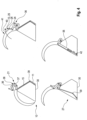
- FIG. 4 now shows a further design variant of a gripping and cutting blade 10 according to the invention with a flat blade base 30 and a specially designed version of the push-out wall 15 and the drive 21 assigned to it.
- the specially designed push-out wall 15 is foldable in such a way that an actuating mechanism 36 attached outside the blade 11, consisting of at least a coupling rod 37 and a rocker 38, can fold the push-out wall 15.
- the push-out wall 15 has at least one hinge connection 39 which enables the push-out wall 15 to be folded in in certain areas. If the gripper is pivoted in the opening direction 40, a rear region 41 of the gripper 13 comes into contact from a certain position with a freely rotatable roller 24 assigned to the actuating mechanism 36.
- the rear region 41 of the gripper 13 thus forms the cam track segment 25 according to the invention, which accommodates the cam track 26
- the further pivoting of the gripper 13 then leads to the actuation mechanism 36 moving the foldable push-out wall 15 into the area of the shovel opening 27, with the bottom area of the push-out wall 15 remaining in contact with the shovel base 30 due to the hinge connection 39.
- the load is thus pushed forward out of the shovel 11.
- This process can be controlled and metered evenly by the movement of the gripper 13.
- the foldable push-out wall 15 is in its rearmost position and loads or bulk goods can be picked up in this state. In this position, the gripper 13 just touches the roller of the rocker 38, but does not yet move it.
- a wear element 42 in the simplest case a roller 24 or a slider.
- the push-out wall 15 can include an extendable element in its bottom area, which can extend and retract under spring, hydraulic or pneumatic pressure.
- the push-out wall 15 can also be assigned a wear element 42 on the bottom side, in the simplest case a roller and/or a slider.
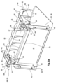
- FIG. 5 shows a further structure according to the invention of the gripping and cutting blade 10.
- the gripping and cutting blade 10 comprises a blade 11 designed as a trough-shaped lower part 12 and an upper part 14 designed as a gripper 13, which is assigned to the top side.
- the tine elements 43 assigned to the gripper 13 are connected to each other in a torsion-resistant manner via transverse webs 44.
- Double flanges 45 are assigned to the crossbars 44 on both sides in a rotationally fixed manner, which are pivotally connected to the side walls 47 of the blade 11 via pivot axes 46.
- the side walls 47 of the blade 11 are connected to one another by a rear wall 48 in the rear area facing away from the blade opening 26.
- the rear wall 48 accommodates stiffening flanges 49 on both sides, which are operatively connected to one another at the top via a stiffening strut 50.
- the double flanges 45 assigned to the gripper 13 are designed in the shape of a double web in their rear area 51, the lower web 52 receiving a bearing point 53, via which the outer double flange 45 is pivotally connected to the respective side wall 47 of the blade 11.
- the inner double flange 45 accommodates a bearing point 54 in its lower web 52, which pivotally connects the inner double flange 45 to the stiffening strut 49 assigned to it. Both bearing points 53, 54 lie on the pivot axis 46 already described.
- the upper web 55 of all double flanges 45 accommodates a further bearing point 56, each of which is penetrated by axle journals 57, with all axle journals 57 aligned on a common pivot axis 58.
- the respective axle journal 57 pivotally accommodates the piston rod-side end of lifting cylinders 22, the piston-side end of which is pivotally connected to the lower part 12 of the gripping and cutting shovel 10, which is designed as a blade 11, with the lifting cylinders 22 themselves in the area are arranged between the respective side wall 47 and the stiffening strut 49 assigned to it.
- the lifting cylinders 22 arranged in pairs are according to the invention Part of the common drive 59, which also includes a coupling mechanism 60 to be described in more detail, which is also coupled to the lower part 12, designed as a blade 11, and the upper part 14, designed as a gripper 13, of the gripping and cutting blade 10. By pressurizing or relieving pressure on the lifting cylinders 22, the gripper 13 can be pivoted about the common pivot axis 58 of the axle journals 57.
- the coupling mechanism 60 initially comprises a support tube 61 which is connected in a rotationally fixed manner to the bearing points 54 received by the lower webs 52 of the respective inner double flanges 45.
- the support tube 61 accommodates fastening flanges 62 in a rotationally fixed manner, which pass through the connecting strut 50 of the blade 11 in slot guides 63 and are firmly connected to the movable push-out wall 15 at the other end.
- the respective fastening flanges 62 each detachably accommodate a cam track segment 25 according to the invention, to which a cam track 26 to be described in more detail is assigned.
- the coupling mechanism 60 includes the already described axle journals 57, each of which accommodates at one end a cranked lever 64 in a rotationally fixed manner, to which a roller 24 is assigned at the end, which is in operative connection with the respective cam track 26 in a manner to be described in more detail.
- the coupling mechanism 60 comprises compression spring cylinders 65, which are also arranged in the area between the inner double flanges 45 and the cam track segments 25 and will also be described in more detail.
- the compression spring cylinders 65 each engage at one end in a pivoting manner on the rear crossbar 44 of the gripper 13 and at the other end in a pivoting manner on a connecting web 66, which is non-rotatable is connected to the support tube 61 of the coupling mechanism 60.
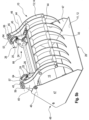
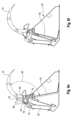
- FIG. 6 now shows the movement sequence in detail. Is the gripping and cutting blade 10 closed ( Fig. 6a ) the piston rods of the lifting cylinders 22 are extended and the coupling mechanism 60 holds the push-out wall 15, 16, designed as a movable rear wall 16, in a rearward position.
- the push-out wall 15 lies against the frame structure 68 of the rear wall 48.
- a clearing slope 69 assigned to the push-out wall in its lower area by means of a hinge 70 is at an angle to the blade base 30.
- the gripper 13 is in its lowest position and closes the blade opening 27.
- the curved track 26 of the curved track segment 25 has an arcuate structure, with the front and rear arcuate areas 71, 72 from a recess 73 are interrupted.
- the roller 24 contacting the cam track 26 is located at the front end of the recess 73 when the gripping and cutting blade 10 is closed.
- the compression spring cylinder 65 which is known per se, is under a preload in this position, which puts the gripper 13 and the push-out wall 15 in a defined relative position 20 holds together.
- the piston rods 74 of the lifting cylinders 22 are now retracted ( Fig. 6b ), the gripping blade 13 is first raised to a position in which the roller 24 touches the rear stop of the recess 73 let into the arcuate areas 71, 72.
- the push-out wall 15 has not yet moved in this position of the roller 24; it is still in its rearward position.
- the compression spring cylinder 65 holds the gripper 13 and the push-out wall 15 in a now changed relative position 20 to one another, the preload force in the compression spring cylinder 65 increasing in a manner known per se.
- the compression spring accumulator 65 is compressed to such an extent that an almost rigid coupling results between the gripper 13 and the push-out wall 15, which results in the gripper 13 opening further and the push-out wall 15 being pivoted into a front area of the blade 11.
- the roller 24 continues to touch the rear stop of the recess 73 let into the arcuate areas 71, 72.
- the compression spring cylinder 65 holds the gripper 13 and the push-out wall 15 in a further changed relative position 20 to one another.
- the removal slope 69 which is accommodated by the push-out wall 15 in its lower region by means of a hinge 70, now assumes an almost stretched position.
- the compression spring accumulator 65 is compressed to such an extent that a rigid coupling results between the gripper 13 and the push-out wall 15, which results in the roller 24 being lifted over the rear stop of the recess 73 and on the cam track 26 of the rear arcuate region 71 of the cam track segment 25 is moved.
- the gripper 13 is in its uppermost position and the push-out wall 15 is in its foremost position.
- the clearing slope 69 which is accommodated by means of a hinge 70, continues to assume an almost stretched position.
- the cam track 26 of at least the rear region 71 of the cam track segment 25, which is now touched by the roller 24 ( Fig. 6e ), has an arc shape 75, in which the radius of curvature R decreases from the end of the recess 73 to the end of the rear region 71 of the curved track segment 25.
- This restoring force causes the push-out wall 15 to move back into its rear position without the gripper 13 leaving its uppermost position.
- the relative position 20 of the gripper 13 and push-out wall 15 is thereby further increased.
- the gripping and cutting shovel 10 can be used as a pure shovel, since the gripper 13 is fixed in its uppermost position, so that the shovel opening 27 is completely released.
Landscapes
- Engineering & Computer Science (AREA)
- Mechanical Engineering (AREA)
- Mining & Mineral Resources (AREA)
- Civil Engineering (AREA)
- General Engineering & Computer Science (AREA)
- Structural Engineering (AREA)
- Operation Control Of Excavators (AREA)
- Harvester Elements (AREA)
- Shovels (AREA)
- Earth Drilling (AREA)
- Forklifts And Lifting Vehicles (AREA)
Claims (25)
- Pelle de préhension ou de coupe (10) constituée d'une partie inférieure (12) réalisée sous forme de pelle (11) et d'une partie supérieure (14) réalisée de préférence sous forme de grappin (13), destinée au prélèvement de produits agricoles sur des lieux de stockage et au chargement de récipients ou de véhicules avec des produits, sachant que la pelle (11) accueille une paroi arrière (16) mobile et qu'au moins la partie supérieure (14) et la paroi arrière (16) mobile peuvent être déplacées dans des positions différentes, sachant que la paroi arrière (16) mobile est réalisée comme paroi d'éjection (15) librement mobile qui est montée sur l'axe de rotation (17) du grappin (13) ou sur un axe de rotation (17) séparé qui se trouve dans une autre position que l'axe de rotation (17) du grappin (13), et sachant que la position relative de la paroi d'éjection (15) et de la partie supérieure (14), l'une par rapport à l'autre, peut être modifiée, caractérisée en ce que la modification de la position relative (20) de la paroi d'éjection (15) et de la partie supérieure (14), l'une par rapport à l'autre, s'effectue à l'aide d'une commande à chemin de came (66), et sachant que la forme de la commande à chemin de came (26) est suivie à l'aide d'un ou plusieurs galets (24) sur un ou plusieurs segments de commande à chemin de came (25), et sachant que le ou les segments de commande à chemin de came (25) sont associés à la paroi arrière (16) mobile et le ou les galets (24) sont associés respectivement à la partie supérieure (14), ou inversement.
- Pelle de préhension ou de coupe (10) selon la revendication 1, caractérisée en ce que la position relative de la paroi d'éjection (15) et de la partie supérieure (14), l'une par rapport à l'autre, peut être modifiée à l'aide de moyens d'entraînement (21) séparés ou à l'aide d'un moyen d'entraînement (21) commun, sachant que la paroi d'éjection (15) peut être déplacée en fonction de la position de la partie supérieure (14) ou indépendamment de la position de la partie supérieure (14).
- Pelle de préhension ou de coupe (10) selon la revendication 2, caractérisée en ce que la paroi d'éjection (15) ne peut être déplacée qu'à partir d'une position du grappin (13) dans laquelle le grappin (13) a libéré l'ouverture de la pelle (27), et en fonction de la position du grappin (13).
- Pelle de préhension ou de coupe (10) selon l'une des revendications 1 ou 2, caractérisée en ce qu'au moins une protection contre les surcharges (67) est associée à la paroi d'éjection (15) et/ou au(x) moyen(s) d'entraînement (21).
- Pelle de préhension ou de coupe (10) selon la revendication 2 ou 3, caractérisée en ce que les moyens d'entraînement (21) séparés sont réalisés sous forme de vérins hydrauliques (22) disposés par paires, sachant que chaque paire de vérins hydrauliques (22) est articulée avec possibilité de pivotement par une extrémité sur la partie inférieure (12) de la pelle de préhension et de coupe (10) et par l'autre extrémité sur la partie supérieure (14) ou à la paroi d'éjection (15).
- Pelle de préhension ou de coupe (10) selon la revendication 5, caractérisée en ce que la paroi d'éjection (15) présente au moins un bras de levier (23) sur lequel est monté au moins un galet (24), et le grappin (13) présente au moins un chemin de came (26) qui comprend un segment de chemin de came (25) et qui, lors du pivotement de la partie supérieure (14), agit sur le galet (24), au nombre d'au moins un, de la paroi d'éjection (15) afin de faire pivoter la paroi d'éjection (15).
- Pelle de préhension ou de coupe (10) selon la revendication 5, caractérisée en ce que la paroi d'éjection (15) présente au moins un bras de levier (23) sur lequel est prévu au moins un chemin de came (26) comprenant un segment de chemin de came (25), et la partie supérieure (14) présente au moins un galet (24) qui, lors du pivotement de la partie supérieure (14), agit sur le chemin de came (26) de la paroi d'éjection (15) afin de faire pivoter la paroi d'éjection (15).
- Pelle de préhension ou de coupe (10) selon l'une des revendications 5 à 7, caractérisée en ce que la commande à chemin de came (66) comprend au moins une bascule (38) qui présente, dans la zone médiane entre les deux extrémités, un point de support par l'intermédiaire duquel la bascule (38) est fixée à la pelle (11), sachant que la bascule (38) accueille à une extrémité au moins un galet (24) sur lequel agit la partie supérieure (14) ou un chemin de came (26) prévu sur la partie supérieure (14), lors du pivotement de la partie supérieure (14), et sachant qu'à l'autre extrémité de la bascule (38), au nombre d'au moins une, un point d'articulation accueille une tige d'accouplement (37) dotée de deux points d'articulation, la tige d'accouplement (37), au nombre d'au moins une, étant reliée par son deuxième point d'articulation avec possibilité de pivotement à la paroi d'éjection (15) ou à un bras de levier (23) relié à la paroi d'éjection (15), et la tige d'accouplement (37), au nombre d'au moins une, transmettant la force et le mouvement, appliqués à la bascule (38) par la partie supérieure (14), à la paroi d'éjection (15), de manière à ce que la paroi d'éjection (15) pivote.
- Pelle de préhension ou de coupe (10) selon la revendication 8, caractérisée en ce que la partie supérieure (14) ou le chemin de came (26), qui est prévu sur la partie supérieure (14) et agit sur le galet (24) de la bascule (38), présente une forme telle que, après avoir atteint la position la plus avancée, la bascule (38), et donc la paroi d'éjection (15), soit immédiatement de nouveau librement mobile et le grappin (13) se trouve dans la position la plus haute.
- Pelle de préhension ou de coupe (10) selon la revendication 2 et/ou 3, caractérisée en ce que le moyen d'entraînement (21) commun comprend des vérins hydrauliques (22) disposés par paires, ainsi qu'un mécanisme d'accouplement (60), sachant que les vérins hydrauliques (22) disposés par paires sont articulés de manière pivotante par une extrémité sur la partie inférieure (12) de la pelle de préhension et de coupe (10) et par l'autre extrémité sur la partie supérieure (14), et le mécanisme d'accouplement (60) est relié par une extrémité à la paroi d'éjection (15), réalisée comme paroi arrière (16) mobile, et par l'autre extrémité à la partie supérieure (14).
- Pelle de préhension ou de coupe (10) selon la revendication 10, caractérisée en ce que le mécanisme d'accouplement (60) comprend une commande à chemin de came (66) et/ou une protection contre les surcharges (67).
- Pelle de préhension ou de coupe (10) selon la revendication 10, caractérisée en ce que la commande à chemin de came (66) comprend un ou plusieurs segments de chemin de came (25), accueillant le chemin de came (26), et un ou plusieurs galets (24) suivant le chemin de came (26), sachant que le chemin de came (26) est associé à la paroi d'éjection (15) mobile et le ou les galets (24) sont associés à la partie supérieure (14).
- Pelle de préhension ou de coupe (10) selon la revendication 12, caractérisée en ce que le segment de chemin de came (25) comprend des parties avant et arrière (71, 72) en forme d'arc et les parties (71, 72) sont séparées l'une de l'autre par un creux (73), le galet (24) étant guidé le long des parties (71, 72) en forme d'arc et du creux (73).
- Pelle de préhension ou de coupe (10) selon la revendication 13, caractérisée en ce qu'au moins la forme en arc (75) du segment arrière (71) en forme d'arc présente un rayon (R) qui diminue depuis le début jusqu'à la fin de ce segment (71) en forme d'arc.
- Pelle de préhension ou de coupe (10) selon la revendication 10, caractérisée en ce qu'au moins un vérin à ressort de compression (65) est associé au mécanisme d'accouplement (60), respectivement dans ses zones d'extrémité latérales, lequel vérin relie la paroi d'éjection (15) et le grappin (13) de manière à ce qu'une modification de la position relative du grappin (13) et de la pelle (11), l'un par rapport à l'autre, devienne possible.
- Pelle de préhension ou de coupe (10) selon l'une des revendications 4 à 15, caractérisée en ce que la protection contre les surcharges (67) est réalisée par la coopération d'un ou plusieurs vérins hydrauliques (22), vérins à ressort de compression (65) et/ou segments de chemin de came (25) associés au mécanisme d'accouplement (60).
- Pelle de préhension ou de coupe (10) selon l'une des revendications précédentes, caractérisée en ce que la pelle (11) présente des parois latérales (47) et une paroi arrière (48) dotée d'entretoises de renfort (49), et les vérins hydrauliques (22) du moyen d'entraînement (21) sont positionnés dans un espace libre formé entre les parois latérales (47) et les entretoises de renfort (49).
- Pelle de préhension ou de coupe (10) selon l'une des revendications précédentes, caractérisée en ce que la pelle de préhension et de coupe (10) comprend un fond de pelle (30) et en ce que le fond de pelle (30) et la paroi arrière (48) sont réalisés avec des contours rectilignes et/ou en forme d'arc.
- Pelle de préhension ou de coupe (10) selon la revendication 18, caractérisée en ce que le fond de pelle (30) est constitué d'au moins une surface plane, et la paroi d'éjection (15) d'au moins deux éléments qui sont reliés dans l'horizontale par au moins une charnière (39, 70), sachant que la paroi d'éjection (15), dans la position déployée où tous les éléments sont alignés et forment une surface plane, est plus longue que la distance maximale possible entre le point de rotation de la paroi d'éjection (15) et le fond de pelle (30), et sachant que la paroi d'éjection (15) est dotée d'au moins un élément de glissement réalisé de préférence sous forme de galet (42), de préférence sur le bord inférieur qui est en contact avec le fond de pelle (30).
- Pelle de préhension ou de coupe (10) selon l'une des revendications 18 ou 19, caractérisée en ce que la paroi d'éjection (15) comporte au moins un élément (35) pouvant être déployé, qui permet de modifier la longueur de la paroi d'éjection (15), et sachant que la paroi d'éjection (15) dotée de l'élément (35) déployable est pourvue d'au moins un élément de glissement réalisé de préférence sous forme de galet (42), notamment sur le bord inférieur qui est en contact avec le fond de pelle (30).
- Pelle de préhension ou de coupe (10) selon l'une des revendications 18 à 20, caractérisée en ce que le mécanisme d'actionnement (36) de la paroi d'éjection (15) présente un rapport de transmission qui, en cas de faible course de pivotement de la partie supérieure (14), déplace la paroi d'éjection (15) depuis la paroi arrière (28) de la pelle (11) jusqu'au bord avant de la pelle (11).
- Pelle de préhension ou de coupe (10) selon l'une des revendications 18 à 21, caractérisée en ce que la paroi arrière (28) et/ou le fond de pelle (30) présente au moins une ouverture à travers laquelle l'espace entre la paroi d'éjection (15) et la paroi arrière (28) de la pelle (11) est accessible.
- Pelle de préhension ou de coupe (10) selon la revendication 17, caractérisée en ce que la paroi d'éjection (15) présente, sur un ou plusieurs côtés, un joint d'étanchéité vis-à-vis des parois latérales (47) et/ou du fond et/ou de la paroi arrière (28) de la pelle (11), et sachant que le joint d'étanchéité est de préférence constitué d'un matériau élastique ou d'un matériau rigide et peut être pressé par une force élastique contre les parois et/ou le fond de pelle (30) et/ou le côté supérieur de l'ouverture de pelle (27).
- Pelle de préhension ou de coupe (10) selon l'une des revendications précédentes, caractérisée en ce que la pelle (11) et/ou la paroi d'éjection (15) présente une butée ou un dispositif qui empêche que la paroi d'éjection (15) ne pivote vers l'avant, hors de la pelle (11).
- Pelle de préhension ou de coupe (10) selon l'une des revendications précédentes, caractérisée en ce que la paroi d'éjection (15) peut être bloquée dans la position située le plus à l'arrière, sur la paroi arrière de pelle (28) ou à proximité de celle-ci.
Applications Claiming Priority (3)
| Application Number | Priority Date | Filing Date | Title |
|---|---|---|---|
| DE202016002855.4U DE202016002855U1 (de) | 2016-04-30 | 2016-04-30 | Greifschaufel/Schneidschaufel mit unabhängiger Ausschiebewand |
| DE202016005627.2U DE202016005627U1 (de) | 2016-04-30 | 2016-09-14 | Greifschaufel/Schneidschaufel mit unabhängiger Ausschiebewand |
| PCT/IB2017/000488 WO2017187257A2 (fr) | 2016-04-30 | 2017-04-28 | Lame de préhension et de coupe munie d'une paroi d'extraction |
Publications (2)
| Publication Number | Publication Date |
|---|---|
| EP3449061A2 EP3449061A2 (fr) | 2019-03-06 |
| EP3449061B1 true EP3449061B1 (fr) | 2024-03-27 |
Family
ID=56233647
Family Applications (1)
| Application Number | Title | Priority Date | Filing Date |
|---|---|---|---|
| EP17743075.8A Active EP3449061B1 (fr) | 2016-04-30 | 2017-04-28 | Lame de préhension et de coupe munie d'une paroi d'extraction |
Country Status (4)
| Country | Link |
|---|---|
| EP (1) | EP3449061B1 (fr) |
| DE (2) | DE202016002855U1 (fr) |
| PL (1) | PL3449061T3 (fr) |
| WO (1) | WO2017187257A2 (fr) |
Families Citing this family (3)
| Publication number | Priority date | Publication date | Assignee | Title |
|---|---|---|---|---|
| DE102016013468A1 (de) | 2016-11-14 | 2018-05-17 | Hesse Metalltechnik Gmbh | Überlastsicherung für eine Ausschiebewand |
| DE202020001195U1 (de) | 2020-03-26 | 2020-04-22 | Thomas Kamhuber | Schaufel mit schwenkbarem Schaufelboden |
| CN117814190A (zh) * | 2024-02-05 | 2024-04-05 | 漳澳国际有限公司 | 一种浮式水产养殖架的收获及翻转设备 |
Citations (1)
| Publication number | Priority date | Publication date | Assignee | Title |
|---|---|---|---|---|
| US3211065A (en) * | 1961-12-26 | 1965-10-12 | Caterpillar Tractor Co | Hydraulic system for a universal bucket of a tractor mounted loader |
Family Cites Families (7)
| Publication number | Priority date | Publication date | Assignee | Title |
|---|---|---|---|---|
| US3110972A (en) * | 1961-10-30 | 1963-11-19 | Soil Mover Co Inc | Scraper with hydraulically controlled components |
| US3523621A (en) * | 1968-04-22 | 1970-08-11 | Caterpillar Tractor Co | Ejector for loader bucket |
| US4032015A (en) * | 1976-06-23 | 1977-06-28 | Adco Company | Bucket cleaner and control for a digging machine |
| US5702227A (en) | 1996-05-13 | 1997-12-30 | Berg; Ronald | Ejector bucket |
| JP2000220163A (ja) * | 1998-11-25 | 2000-08-08 | Susumu Nakazono | バケット及び挟持具を有する油圧ショベル |
| DE202008002254U1 (de) | 2008-02-18 | 2008-05-08 | Frank Föckersperger GmbH | Schaufel für einen Radlader oder Hoflader |
| DE102011010788B4 (de) * | 2011-02-09 | 2012-10-18 | Robin Bäuscher | Ladeeinrichtung für landwirtschaftliches Transportgut |
-
2016
- 2016-04-30 DE DE202016002855.4U patent/DE202016002855U1/de not_active Expired - Lifetime
- 2016-09-14 DE DE202016005627.2U patent/DE202016005627U1/de active Active
-
2017
- 2017-04-28 EP EP17743075.8A patent/EP3449061B1/fr active Active
- 2017-04-28 PL PL17743075.8T patent/PL3449061T3/pl unknown
- 2017-04-28 WO PCT/IB2017/000488 patent/WO2017187257A2/fr not_active Ceased
Patent Citations (1)
| Publication number | Priority date | Publication date | Assignee | Title |
|---|---|---|---|---|
| US3211065A (en) * | 1961-12-26 | 1965-10-12 | Caterpillar Tractor Co | Hydraulic system for a universal bucket of a tractor mounted loader |
Also Published As
| Publication number | Publication date |
|---|---|
| WO2017187257A3 (fr) | 2017-12-28 |
| WO2017187257A2 (fr) | 2017-11-02 |
| PL3449061T3 (pl) | 2024-07-29 |
| DE202016005627U1 (de) | 2016-11-15 |
| DE202016002855U1 (de) | 2016-06-08 |
| EP3449061A2 (fr) | 2019-03-06 |
Similar Documents
| Publication | Publication Date | Title |
|---|---|---|
| DE69404070T2 (de) | Gerät, das einem Fahrzeug ermöglicht, eine Ladung, wie z.B. einen Kübel, aufzunehmen oder auf dem Boden abzusetzen und ihn evtl. zu entleeren | |
| EP3704928B1 (fr) | Machine de récolte et procédé de récolte au moyen d'une machine de récolte | |
| DE2458811C3 (de) | Vorrichtung an einem Lastkraftwagen | |
| EP3617130B1 (fr) | Dispositif de chargement pourvu de dispositif de chargement télescopique | |
| DE2316375A1 (de) | Ballentransportwagen mit einer entladevorrichtung fuer einzelne ballen | |
| DE2753069A1 (de) | Erntemaschine | |
| EP4028599B1 (fr) | Élément de préhension | |
| EP3449061A2 (fr) | Lame de préhension et de coupe munie d'une paroi d'extraction | |
| EP1142467B1 (fr) | Dispositif de cueillette de céréales | |
| DE2411726B1 (de) | Stapelpresse für Feldfrüchte | |
| EP3014978B1 (fr) | Presse a balles rondes equipee d'une enrubanneuse | |
| EP3090619B1 (fr) | Bec cueilleur de récolte disposée en rangées | |
| DE2365163C2 (de) | Ladefahrzeug | |
| DE1166700B (de) | Lastfahrzeug mit Schrappeinrichtung | |
| DE2027259B2 (de) | Be- und Entladeeinrichtung für Behälter od.dgl. an Fahrzeugen | |
| DE202015106899U1 (de) | Abschiebeschaufel für Stückgut | |
| DE4035334A1 (de) | Ladewagen | |
| DE2115231A1 (de) | Steuervorrichtung für ein Verschiebegestell auf einem Ballentransportwagen | |
| WO2025061998A1 (fr) | Récolteuse de betteraves | |
| EP3669630B1 (fr) | Unité de roue de support pour un engin d'abattage-façonnage agricole | |
| EP0456796B1 (fr) | Dispositif de transport de minerais exploites | |
| DE202007012649U1 (de) | Ladewagen | |
| DE202023100745U1 (de) | Schneidwerk für halmförmiges landwirtschaftliches Erntegut | |
| AT516804A2 (de) | Hochkippschaufel | |
| DE202010000352U1 (de) | Anbaugerät |
Legal Events
| Date | Code | Title | Description |
|---|---|---|---|
| STAA | Information on the status of an ep patent application or granted ep patent |
Free format text: STATUS: UNKNOWN |
|
| STAA | Information on the status of an ep patent application or granted ep patent |
Free format text: STATUS: THE INTERNATIONAL PUBLICATION HAS BEEN MADE |
|
| PUAI | Public reference made under article 153(3) epc to a published international application that has entered the european phase |
Free format text: ORIGINAL CODE: 0009012 |
|
| STAA | Information on the status of an ep patent application or granted ep patent |
Free format text: STATUS: REQUEST FOR EXAMINATION WAS MADE |
|
| 17P | Request for examination filed |
Effective date: 20181130 |
|
| AK | Designated contracting states |
Kind code of ref document: A2 Designated state(s): AL AT BE BG CH CY CZ DE DK EE ES FI FR GB GR HR HU IE IS IT LI LT LU LV MC MK MT NL NO PL PT RO RS SE SI SK SM TR |
|
| AX | Request for extension of the european patent |
Extension state: BA ME |
|
| DAV | Request for validation of the european patent (deleted) | ||
| DAX | Request for extension of the european patent (deleted) | ||
| STAA | Information on the status of an ep patent application or granted ep patent |
Free format text: STATUS: EXAMINATION IS IN PROGRESS |
|
| 17Q | First examination report despatched |
Effective date: 20220429 |
|
| P01 | Opt-out of the competence of the unified patent court (upc) registered |
Effective date: 20230516 |
|
| GRAP | Despatch of communication of intention to grant a patent |
Free format text: ORIGINAL CODE: EPIDOSNIGR1 |
|
| STAA | Information on the status of an ep patent application or granted ep patent |
Free format text: STATUS: GRANT OF PATENT IS INTENDED |
|
| INTG | Intention to grant announced |
Effective date: 20240104 |
|
| GRAS | Grant fee paid |
Free format text: ORIGINAL CODE: EPIDOSNIGR3 |
|
| GRAA | (expected) grant |
Free format text: ORIGINAL CODE: 0009210 |
|
| STAA | Information on the status of an ep patent application or granted ep patent |
Free format text: STATUS: THE PATENT HAS BEEN GRANTED |
|
| AK | Designated contracting states |
Kind code of ref document: B1 Designated state(s): AL AT BE BG CH CY CZ DE DK EE ES FI FR GB GR HR HU IE IS IT LI LT LU LV MC MK MT NL NO PL PT RO RS SE SI SK SM TR |
|
| REG | Reference to a national code |
Ref country code: GB Ref legal event code: FG4D Free format text: NOT ENGLISH |
|
| REG | Reference to a national code |
Ref country code: CH Ref legal event code: EP |
|
| REG | Reference to a national code |
Ref country code: DE Ref legal event code: R096 Ref document number: 502017015968 Country of ref document: DE |
|
| REG | Reference to a national code |
Ref country code: IE Ref legal event code: FG4D Free format text: LANGUAGE OF EP DOCUMENT: GERMAN |
|
| PG25 | Lapsed in a contracting state [announced via postgrant information from national office to epo] |
Ref country code: LT Free format text: LAPSE BECAUSE OF FAILURE TO SUBMIT A TRANSLATION OF THE DESCRIPTION OR TO PAY THE FEE WITHIN THE PRESCRIBED TIME-LIMIT Effective date: 20240327 |
|
| REG | Reference to a national code |
Ref country code: LT Ref legal event code: MG9D |
|
| PG25 | Lapsed in a contracting state [announced via postgrant information from national office to epo] |
Ref country code: GR Free format text: LAPSE BECAUSE OF FAILURE TO SUBMIT A TRANSLATION OF THE DESCRIPTION OR TO PAY THE FEE WITHIN THE PRESCRIBED TIME-LIMIT Effective date: 20240628 |
|
| PG25 | Lapsed in a contracting state [announced via postgrant information from national office to epo] |
Ref country code: HR Free format text: LAPSE BECAUSE OF FAILURE TO SUBMIT A TRANSLATION OF THE DESCRIPTION OR TO PAY THE FEE WITHIN THE PRESCRIBED TIME-LIMIT Effective date: 20240327 Ref country code: RS Free format text: LAPSE BECAUSE OF FAILURE TO SUBMIT A TRANSLATION OF THE DESCRIPTION OR TO PAY THE FEE WITHIN THE PRESCRIBED TIME-LIMIT Effective date: 20240627 |
|
| PG25 | Lapsed in a contracting state [announced via postgrant information from national office to epo] |
Ref country code: RS Free format text: LAPSE BECAUSE OF FAILURE TO SUBMIT A TRANSLATION OF THE DESCRIPTION OR TO PAY THE FEE WITHIN THE PRESCRIBED TIME-LIMIT Effective date: 20240627 Ref country code: NO Free format text: LAPSE BECAUSE OF FAILURE TO SUBMIT A TRANSLATION OF THE DESCRIPTION OR TO PAY THE FEE WITHIN THE PRESCRIBED TIME-LIMIT Effective date: 20240627 Ref country code: LT Free format text: LAPSE BECAUSE OF FAILURE TO SUBMIT A TRANSLATION OF THE DESCRIPTION OR TO PAY THE FEE WITHIN THE PRESCRIBED TIME-LIMIT Effective date: 20240327 Ref country code: HR Free format text: LAPSE BECAUSE OF FAILURE TO SUBMIT A TRANSLATION OF THE DESCRIPTION OR TO PAY THE FEE WITHIN THE PRESCRIBED TIME-LIMIT Effective date: 20240327 Ref country code: GR Free format text: LAPSE BECAUSE OF FAILURE TO SUBMIT A TRANSLATION OF THE DESCRIPTION OR TO PAY THE FEE WITHIN THE PRESCRIBED TIME-LIMIT Effective date: 20240628 Ref country code: FI Free format text: LAPSE BECAUSE OF FAILURE TO SUBMIT A TRANSLATION OF THE DESCRIPTION OR TO PAY THE FEE WITHIN THE PRESCRIBED TIME-LIMIT Effective date: 20240327 Ref country code: BG Free format text: LAPSE BECAUSE OF FAILURE TO SUBMIT A TRANSLATION OF THE DESCRIPTION OR TO PAY THE FEE WITHIN THE PRESCRIBED TIME-LIMIT Effective date: 20240327 |
|
| REG | Reference to a national code |
Ref country code: NL Ref legal event code: MP Effective date: 20240327 |
|
| PG25 | Lapsed in a contracting state [announced via postgrant information from national office to epo] |
Ref country code: SE Free format text: LAPSE BECAUSE OF FAILURE TO SUBMIT A TRANSLATION OF THE DESCRIPTION OR TO PAY THE FEE WITHIN THE PRESCRIBED TIME-LIMIT Effective date: 20240327 Ref country code: LV Free format text: LAPSE BECAUSE OF FAILURE TO SUBMIT A TRANSLATION OF THE DESCRIPTION OR TO PAY THE FEE WITHIN THE PRESCRIBED TIME-LIMIT Effective date: 20240327 |
|
| PG25 | Lapsed in a contracting state [announced via postgrant information from national office to epo] |
Ref country code: NL Free format text: LAPSE BECAUSE OF FAILURE TO SUBMIT A TRANSLATION OF THE DESCRIPTION OR TO PAY THE FEE WITHIN THE PRESCRIBED TIME-LIMIT Effective date: 20240327 |
|
| PG25 | Lapsed in a contracting state [announced via postgrant information from national office to epo] |
Ref country code: NL Free format text: LAPSE BECAUSE OF FAILURE TO SUBMIT A TRANSLATION OF THE DESCRIPTION OR TO PAY THE FEE WITHIN THE PRESCRIBED TIME-LIMIT Effective date: 20240327 |
|
| PG25 | Lapsed in a contracting state [announced via postgrant information from national office to epo] |
Ref country code: IS Free format text: LAPSE BECAUSE OF FAILURE TO SUBMIT A TRANSLATION OF THE DESCRIPTION OR TO PAY THE FEE WITHIN THE PRESCRIBED TIME-LIMIT Effective date: 20240727 |
|
| PG25 | Lapsed in a contracting state [announced via postgrant information from national office to epo] |
Ref country code: PT Free format text: LAPSE BECAUSE OF FAILURE TO SUBMIT A TRANSLATION OF THE DESCRIPTION OR TO PAY THE FEE WITHIN THE PRESCRIBED TIME-LIMIT Effective date: 20240729 Ref country code: SM Free format text: LAPSE BECAUSE OF FAILURE TO SUBMIT A TRANSLATION OF THE DESCRIPTION OR TO PAY THE FEE WITHIN THE PRESCRIBED TIME-LIMIT Effective date: 20240327 |
|
| PG25 | Lapsed in a contracting state [announced via postgrant information from national office to epo] |
Ref country code: ES Free format text: LAPSE BECAUSE OF FAILURE TO SUBMIT A TRANSLATION OF THE DESCRIPTION OR TO PAY THE FEE WITHIN THE PRESCRIBED TIME-LIMIT Effective date: 20240327 |
|
| PG25 | Lapsed in a contracting state [announced via postgrant information from national office to epo] |
Ref country code: CZ Free format text: LAPSE BECAUSE OF FAILURE TO SUBMIT A TRANSLATION OF THE DESCRIPTION OR TO PAY THE FEE WITHIN THE PRESCRIBED TIME-LIMIT Effective date: 20240327 Ref country code: EE Free format text: LAPSE BECAUSE OF FAILURE TO SUBMIT A TRANSLATION OF THE DESCRIPTION OR TO PAY THE FEE WITHIN THE PRESCRIBED TIME-LIMIT Effective date: 20240327 |
|
| PG25 | Lapsed in a contracting state [announced via postgrant information from national office to epo] |
Ref country code: SK Free format text: LAPSE BECAUSE OF FAILURE TO SUBMIT A TRANSLATION OF THE DESCRIPTION OR TO PAY THE FEE WITHIN THE PRESCRIBED TIME-LIMIT Effective date: 20240327 |
|
| PG25 | Lapsed in a contracting state [announced via postgrant information from national office to epo] |
Ref country code: SM Free format text: LAPSE BECAUSE OF FAILURE TO SUBMIT A TRANSLATION OF THE DESCRIPTION OR TO PAY THE FEE WITHIN THE PRESCRIBED TIME-LIMIT Effective date: 20240327 Ref country code: SK Free format text: LAPSE BECAUSE OF FAILURE TO SUBMIT A TRANSLATION OF THE DESCRIPTION OR TO PAY THE FEE WITHIN THE PRESCRIBED TIME-LIMIT Effective date: 20240327 Ref country code: RO Free format text: LAPSE BECAUSE OF FAILURE TO SUBMIT A TRANSLATION OF THE DESCRIPTION OR TO PAY THE FEE WITHIN THE PRESCRIBED TIME-LIMIT Effective date: 20240327 Ref country code: PT Free format text: LAPSE BECAUSE OF FAILURE TO SUBMIT A TRANSLATION OF THE DESCRIPTION OR TO PAY THE FEE WITHIN THE PRESCRIBED TIME-LIMIT Effective date: 20240729 Ref country code: IS Free format text: LAPSE BECAUSE OF FAILURE TO SUBMIT A TRANSLATION OF THE DESCRIPTION OR TO PAY THE FEE WITHIN THE PRESCRIBED TIME-LIMIT Effective date: 20240727 Ref country code: ES Free format text: LAPSE BECAUSE OF FAILURE TO SUBMIT A TRANSLATION OF THE DESCRIPTION OR TO PAY THE FEE WITHIN THE PRESCRIBED TIME-LIMIT Effective date: 20240327 Ref country code: EE Free format text: LAPSE BECAUSE OF FAILURE TO SUBMIT A TRANSLATION OF THE DESCRIPTION OR TO PAY THE FEE WITHIN THE PRESCRIBED TIME-LIMIT Effective date: 20240327 Ref country code: CZ Free format text: LAPSE BECAUSE OF FAILURE TO SUBMIT A TRANSLATION OF THE DESCRIPTION OR TO PAY THE FEE WITHIN THE PRESCRIBED TIME-LIMIT Effective date: 20240327 |
|
| REG | Reference to a national code |
Ref country code: CH Ref legal event code: PL |
|
| PG25 | Lapsed in a contracting state [announced via postgrant information from national office to epo] |
Ref country code: IT Free format text: LAPSE BECAUSE OF FAILURE TO SUBMIT A TRANSLATION OF THE DESCRIPTION OR TO PAY THE FEE WITHIN THE PRESCRIBED TIME-LIMIT Effective date: 20240327 |
|
| PG25 | Lapsed in a contracting state [announced via postgrant information from national office to epo] |
Ref country code: LU Free format text: LAPSE BECAUSE OF NON-PAYMENT OF DUE FEES Effective date: 20240428 |
|
| REG | Reference to a national code |
Ref country code: BE Ref legal event code: MM Effective date: 20240430 |
|
| PG25 | Lapsed in a contracting state [announced via postgrant information from national office to epo] |
Ref country code: LU Free format text: LAPSE BECAUSE OF NON-PAYMENT OF DUE FEES Effective date: 20240428 Ref country code: IT Free format text: LAPSE BECAUSE OF FAILURE TO SUBMIT A TRANSLATION OF THE DESCRIPTION OR TO PAY THE FEE WITHIN THE PRESCRIBED TIME-LIMIT Effective date: 20240327 |
|
| REG | Reference to a national code |
Ref country code: DE Ref legal event code: R097 Ref document number: 502017015968 Country of ref document: DE |
|
| PG25 | Lapsed in a contracting state [announced via postgrant information from national office to epo] |
Ref country code: MC Free format text: LAPSE BECAUSE OF FAILURE TO SUBMIT A TRANSLATION OF THE DESCRIPTION OR TO PAY THE FEE WITHIN THE PRESCRIBED TIME-LIMIT Effective date: 20240327 |
|
| PG25 | Lapsed in a contracting state [announced via postgrant information from national office to epo] |
Ref country code: DK Free format text: LAPSE BECAUSE OF FAILURE TO SUBMIT A TRANSLATION OF THE DESCRIPTION OR TO PAY THE FEE WITHIN THE PRESCRIBED TIME-LIMIT Effective date: 20240327 |
|
| PG25 | Lapsed in a contracting state [announced via postgrant information from national office to epo] |
Ref country code: BE Free format text: LAPSE BECAUSE OF NON-PAYMENT OF DUE FEES Effective date: 20240430 |
|
| PG25 | Lapsed in a contracting state [announced via postgrant information from national office to epo] |
Ref country code: MC Free format text: LAPSE BECAUSE OF FAILURE TO SUBMIT A TRANSLATION OF THE DESCRIPTION OR TO PAY THE FEE WITHIN THE PRESCRIBED TIME-LIMIT Effective date: 20240327 Ref country code: DK Free format text: LAPSE BECAUSE OF FAILURE TO SUBMIT A TRANSLATION OF THE DESCRIPTION OR TO PAY THE FEE WITHIN THE PRESCRIBED TIME-LIMIT Effective date: 20240327 Ref country code: BE Free format text: LAPSE BECAUSE OF NON-PAYMENT OF DUE FEES Effective date: 20240430 Ref country code: CH Free format text: LAPSE BECAUSE OF NON-PAYMENT OF DUE FEES Effective date: 20240430 |
|
| PLBE | No opposition filed within time limit |
Free format text: ORIGINAL CODE: 0009261 |
|
| STAA | Information on the status of an ep patent application or granted ep patent |
Free format text: STATUS: NO OPPOSITION FILED WITHIN TIME LIMIT |
|
| 26N | No opposition filed |
Effective date: 20250103 |
|
| PG25 | Lapsed in a contracting state [announced via postgrant information from national office to epo] |
Ref country code: IE Free format text: LAPSE BECAUSE OF NON-PAYMENT OF DUE FEES Effective date: 20240428 |
|
| PG25 | Lapsed in a contracting state [announced via postgrant information from national office to epo] |
Ref country code: SI Free format text: LAPSE BECAUSE OF FAILURE TO SUBMIT A TRANSLATION OF THE DESCRIPTION OR TO PAY THE FEE WITHIN THE PRESCRIBED TIME-LIMIT Effective date: 20240327 |
|
| REG | Reference to a national code |
Ref country code: AT Ref legal event code: MM01 Ref document number: 1670010 Country of ref document: AT Kind code of ref document: T Effective date: 20240428 |
|
| PG25 | Lapsed in a contracting state [announced via postgrant information from national office to epo] |
Ref country code: AT Free format text: LAPSE BECAUSE OF NON-PAYMENT OF DUE FEES Effective date: 20240428 |
|
| PG25 | Lapsed in a contracting state [announced via postgrant information from national office to epo] |
Ref country code: CY Free format text: LAPSE BECAUSE OF FAILURE TO SUBMIT A TRANSLATION OF THE DESCRIPTION OR TO PAY THE FEE WITHIN THE PRESCRIBED TIME-LIMIT; INVALID AB INITIO Effective date: 20170428 |
|
| PG25 | Lapsed in a contracting state [announced via postgrant information from national office to epo] |
Ref country code: HU Free format text: LAPSE BECAUSE OF FAILURE TO SUBMIT A TRANSLATION OF THE DESCRIPTION OR TO PAY THE FEE WITHIN THE PRESCRIBED TIME-LIMIT; INVALID AB INITIO Effective date: 20170428 |
|
| PG25 | Lapsed in a contracting state [announced via postgrant information from national office to epo] |
Ref country code: TR Free format text: LAPSE BECAUSE OF FAILURE TO SUBMIT A TRANSLATION OF THE DESCRIPTION OR TO PAY THE FEE WITHIN THE PRESCRIBED TIME-LIMIT Effective date: 20240327 |
|
| PGFP | Annual fee paid to national office [announced via postgrant information from national office to epo] |
Ref country code: GB Payment date: 20260423 Year of fee payment: 10 Ref country code: PL Payment date: 20260416 Year of fee payment: 10 |
|
| PGFP | Annual fee paid to national office [announced via postgrant information from national office to epo] |
Ref country code: DE Payment date: 20260422 Year of fee payment: 10 |
|
| PGFP | Annual fee paid to national office [announced via postgrant information from national office to epo] |
Ref country code: FR Payment date: 20260420 Year of fee payment: 10 |