EP3449113B1 - Filtre à air avec élément de filtre à air plat - Google Patents
Filtre à air avec élément de filtre à air plat Download PDFInfo
- Publication number
- EP3449113B1 EP3449113B1 EP17723296.4A EP17723296A EP3449113B1 EP 3449113 B1 EP3449113 B1 EP 3449113B1 EP 17723296 A EP17723296 A EP 17723296A EP 3449113 B1 EP3449113 B1 EP 3449113B1
- Authority
- EP
- European Patent Office
- Prior art keywords
- air filter
- recess
- housing
- filter
- sealing element
- Prior art date
- Legal status (The legal status is an assumption and is not a legal conclusion. Google has not performed a legal analysis and makes no representation as to the accuracy of the status listed.)
- Active
Links
Images






Classifications
-
- F—MECHANICAL ENGINEERING; LIGHTING; HEATING; WEAPONS; BLASTING
- F02—COMBUSTION ENGINES; HOT-GAS OR COMBUSTION-PRODUCT ENGINE PLANTS
- F02M—SUPPLYING COMBUSTION ENGINES IN GENERAL WITH COMBUSTIBLE MIXTURES OR CONSTITUENTS THEREOF
- F02M35/00—Combustion-air cleaners, air intakes, intake silencers, or induction systems specially adapted for, or arranged on, internal-combustion engines
- F02M35/02—Air cleaners
- F02M35/024—Air cleaners using filters, e.g. moistened
- F02M35/02475—Air cleaners using filters, e.g. moistened characterised by the shape of the filter element
- F02M35/02491—Flat filter elements, e.g. rectangular
-
- B—PERFORMING OPERATIONS; TRANSPORTING
- B01—PHYSICAL OR CHEMICAL PROCESSES OR APPARATUS IN GENERAL
- B01D—SEPARATION
- B01D46/00—Filters or filtering processes specially modified for separating dispersed particles from gases or vapours
- B01D46/0002—Casings; Housings; Frame constructions
- B01D46/0005—Mounting of filtering elements within casings, housings or frames
-
- B—PERFORMING OPERATIONS; TRANSPORTING
- B01—PHYSICAL OR CHEMICAL PROCESSES OR APPARATUS IN GENERAL
- B01D—SEPARATION
- B01D46/00—Filters or filtering processes specially modified for separating dispersed particles from gases or vapours
- B01D46/10—Particle separators, e.g. dust precipitators, using filter plates, sheets or pads having plane surfaces
-
- B—PERFORMING OPERATIONS; TRANSPORTING
- B01—PHYSICAL OR CHEMICAL PROCESSES OR APPARATUS IN GENERAL
- B01D—SEPARATION
- B01D46/00—Filters or filtering processes specially modified for separating dispersed particles from gases or vapours
- B01D46/42—Auxiliary equipment or operation thereof
- B01D46/4236—Reducing noise or vibration emissions
-
- F—MECHANICAL ENGINEERING; LIGHTING; HEATING; WEAPONS; BLASTING
- F02—COMBUSTION ENGINES; HOT-GAS OR COMBUSTION-PRODUCT ENGINE PLANTS
- F02M—SUPPLYING COMBUSTION ENGINES IN GENERAL WITH COMBUSTIBLE MIXTURES OR CONSTITUENTS THEREOF
- F02M35/00—Combustion-air cleaners, air intakes, intake silencers, or induction systems specially adapted for, or arranged on, internal-combustion engines
- F02M35/02—Air cleaners
- F02M35/0201—Housings; Casings; Frame constructions; Lids; Manufacturing or assembling thereof
- F02M35/0202—Manufacturing or assembling; Materials for air cleaner housings
- F02M35/0203—Manufacturing or assembling; Materials for air cleaner housings by using clamps, catches, locks or the like, e.g. for disposable plug-in filter cartridges
-
- F—MECHANICAL ENGINEERING; LIGHTING; HEATING; WEAPONS; BLASTING
- F02—COMBUSTION ENGINES; HOT-GAS OR COMBUSTION-PRODUCT ENGINE PLANTS
- F02M—SUPPLYING COMBUSTION ENGINES IN GENERAL WITH COMBUSTIBLE MIXTURES OR CONSTITUENTS THEREOF
- F02M35/00—Combustion-air cleaners, air intakes, intake silencers, or induction systems specially adapted for, or arranged on, internal-combustion engines
- F02M35/02—Air cleaners
- F02M35/024—Air cleaners using filters, e.g. moistened
- F02M35/02441—Materials or structure of filter elements, e.g. foams
-
- B—PERFORMING OPERATIONS; TRANSPORTING
- B01—PHYSICAL OR CHEMICAL PROCESSES OR APPARATUS IN GENERAL
- B01D—SEPARATION
- B01D2271/00—Sealings for filters specially adapted for separating dispersed particles from gases or vapours
- B01D2271/02—Gaskets, sealings
-
- B—PERFORMING OPERATIONS; TRANSPORTING
- B01—PHYSICAL OR CHEMICAL PROCESSES OR APPARATUS IN GENERAL
- B01D—SEPARATION
- B01D2275/00—Filter media structures for filters specially adapted for separating dispersed particles from gases or vapours
- B01D2275/20—Shape of filtering material
- B01D2275/206—Special forms, e.g. adapted to a certain housing
-
- B—PERFORMING OPERATIONS; TRANSPORTING
- B01—PHYSICAL OR CHEMICAL PROCESSES OR APPARATUS IN GENERAL
- B01D—SEPARATION
- B01D2279/00—Filters adapted for separating dispersed particles from gases or vapours specially modified for specific uses
- B01D2279/60—Filters adapted for separating dispersed particles from gases or vapours specially modified for specific uses for the intake of internal combustion engines or turbines
Definitions
- the invention relates to an air filter, in particular an air filter in the air intake tract of an internal combustion engine, and to the use of a flat air filter element in such an air filter.
- Air filters are used in the air intake tract of internal combustion engines, such as motor vehicles, in order to clean the combustion air supplied to the internal combustion engine from impurities.
- a pressure loss occurs, which can reduce the performance of the internal combustion engine.
- a filter area of the filter element can be increased.
- the installation space available for the air filter is often very limited, for example in the engine compartment of a motor vehicle, so that the air filter cannot be sufficiently enlarged.
- a filter element for a cabin filter of an air conditioning or ventilation system which has a pentagonal bellows, the bellows being composed of a first rectangular partial bellows and a second square partial bellows. This allows the amount of waste filter material to be reduced when producing the pentagonal bellows.
- DE 203 10 833 U1 describes a filter insert for installation in a flow channel with a specified installation cross section.
- the filter insert has an outer contour adapted to the installation cross section of the flow channel, with a plastic part being placed on a bellows in order to adapt the bellows to the installation cross section.
- the bellows can be cut in a trapezoidal shape to avoid waste.
- EP 1 144 083 B1 shows an air filter for internal combustion engines, which has a housing with a cover in which a filter insert is inserted.
- the housing has a strut which extends between two wall parts of the housing to be stiffened through a recess in the filter insert.
- a filter device in the DE 10 2015 011 661 A1 a filter device is described, the filter element of which consists of at least two adjacently arranged individual filters.
- the individual filters delimit on at least two sides a gas collection space that is open at the edge and is fluidly connected to the clean side of the individual filters and serves to receive the cleaned gas.
- a filter element with a bellows and a circumferential seal is disclosed, the bellows having a through opening between the clean side and the raw side.
- the WO 2015/075104 A1 describes filter elements with a bellows with opposite sealed end edge surfaces and at least two element sections, with an end edge surface experiencing a change in direction from one element section to the other element section.
- the flat air filter element according to the invention is particularly suitable for an air filter according to the invention in the air intake tract of an internal combustion engine and has a filter medium made of a cellulose material.
- Cellulose material has proven itself in practice as a material for air filters, especially since good filter performance with low pressure loss can be achieved with cellulose material.
- cellulose is inexpensive to obtain and can be disposed of in an environmentally friendly manner.
- the filter medium has a circumferential sealing element.
- the sealing element makes it possible to seal the filter medium against a filter housing, so that no unfiltered air can flow past the filter medium in the sense of a bypass flow.
- the sealing element and the filter medium have at least one recess on an outer contour of the flat air filter element.
- the flat air filter element can be adapted to a contour of the filter housing with the recess.
- the flat air filter element therefore does not have to be reduced in size overall in order to be able to take into account a recess on an inner wall of the filter housing, ie a local narrowing of the cross-section of the filter housing. Rather, the flat air filter element according to the invention can be retracted
- the outer contour surrounds the recess on the inner wall of the filter housing and extends next to the recess up to the inner wall of the filter housing.
- the flat air filter element can, for example, have a non-convex outer contour in the area of the recess.
- the said recess of the filter housing may be required, for example, for a closure element of the filter housing.
- the sealing element typically projects laterally beyond the filter medium by a certain amount, for example by 0.5 cm to 2 cm.
- the recess is preferably formed equally on the filter medium and on the sealing element, so that a uniform projection of the sealing element beyond the filter medium is obtained.
- a circumferential retaining groove for engaging a housing part of a filter housing is formed on the sealing element. This allows a defined and secure fit of the flat air filter element to be set up in the filter housing.
- the positive connection between the sealing element and the housing part can prevent the sealing element from slipping out of its clamping on the filter housing. This improves the operational reliability of the flat air filter element.
- the sealing element preferably has a curved outside.
- the curved outside can be formed opposite the retaining groove on the sealing element.
- the curved outside can be surrounded by another housing part.
- the recess is formed on a corner region of the flat air filter element.
- the recess can advantageously be designed in the form of a chamfer. The take-back can therefore be produced particularly easily in terms of production technology.
- An advantageous embodiment of the invention is characterized in that Recess, in particular in the middle, is formed on a side edge of the flat air filter element.
- a closure element for a filter housing in which the flat air filter element is installed can then be provided in the middle of the side edge.
- the recess is designed as a curved (rounded, concave) indentation.
- a recess can be particularly close to a recess in the filter housing.
- the filter area of the flat air filter element can thus be maximized.
- a rounded indentation can also improve the flow of force in the area of the recess, especially through the sealing element.
- the recess can have an engagement depth of at least 10 mm, preferably at least 10.5 mm.
- the indentation formed by the recess can protrude at least 10 mm, preferably at least 10.5 mm, deep into the sealing element or the filter medium.
- the recess can have an engagement depth of at least 10 mm, preferably at least 10.5 mm.
- the closure element in particular a screw or a tension spring, can be arranged on the filter housing without it protruding beyond it.
- the closure element can be positioned within a housing envelope of the filter housing.
- the flat air filter element can advantageously have several recesses.
- several closure elements for a filter housing can then be arranged on the flat air filter element to save space.
- the filter medium is designed as a zigzag folded bellows. This means that the flat air filter element can be designed with a particularly large filter area become.
- the filter medium can advantageously be cut to size in the unrolled state and only then folded into a bellows. This simplifies production.
- a laser cutting system can preferably be used for cutting.
- the filter medium has end edges glued together, in particular end edge gluing. In this way, the folds of the bellows can be sealed against one another particularly easily and reliably.
- the gluing is preferably water-resistant in order to ensure long-term stability of the gluing even when the air humidity is high or when the flat air filter element comes into contact with water.
- the so-called front edge gluing can be produced by applying at least one so-called glue bead to a particularly unfolded filter medium.
- the glue bead is preferably formed from an adhesive, preferably a hot-melt adhesive applied in a molten state, for example made of polyamide or polyester.
- the filter medium can then be folded into the bellows so that adjacent folds of the bellows are connected to one another.
- glue beads or sections of the glue bead of adjacent folds overlap.
- two glue beads or two sections of the glue bead can converge towards one another, in particular overlapping or alternatively not overlapping.
- the glue bead can usually run uninterrupted and in particular parallel or essentially parallel to the front edge or edges of the filter medium.
- the end edge gluing runs at least in the area of the recess, preferably along the entire end faces of the flat air filter element, at a tangential angle of at most 45° to the main direction of the folded filter medium, ie to the end face of the folded filter medium.
- the curve formed by the parts of the front edge gluing visible in the folded state in the area of the fold tips has a maximum angle of 45° to the front side and thus has a minimum angle of 45° to the folded edges. This makes it easier to produce the glue bead and thus the front edge gluing in a continuous and preferably consistently tight manner.
- the main direction is to be understood as meaning the orientation or direction of the front edge of the unfolded filter medium, which forms the front edges, outside the area of an indentation that forms the recess.
- the main direction results from the direction of the front edge of the unfolded filter medium, ignoring the indentation; this generally corresponds to the machine direction.
- the glue bead can in particular run without kinks.
- the maximum achieved tangential angle of the glue bead can also be selected depending on the width of the glue bead and/or the fold spacing or fold pitch of the filter medium.
- the sealing element can sealingly connect to the front edge gluing along a seal connection contour, in particular in a form-fitting manner.
- the seal connection contour can enclose the front edge gluing in a form-fitting manner.
- the seal connection contour can extend beyond and/or cover the end edge gluing radially (seen from the outer end face inwards), in particular on the clean side.
- seal connection contour of the sealing element and the end edge gluing run parallel to one another in the area of the recess, preferably along the entire end faces of the flat air filter element.
- the sealing element and/or the end edges run parallel to the end edge gluing in the area of the recess, preferably along the entire end faces of the flat air filter element. It is also or alternatively conceivable that in a transition region of the recess the distance between the outer contour and the end edge gluing and/or between a line of the sealing element and the end edge gluing is increased compared to adjacent areas.
- the sealing element is made of polyurethane.
- Polyurethane is easy to process and has suitable properties to be used as the sealing element.
- the sealing element is preferably molded or foamed directly onto the flat air filter element. This allows the production of the flat air filter element to be simplified. Furthermore, it can be achieved that the sealing element itself is attached to the flat air filter element in a sealing manner. If necessary, the flat air filter element can therefore consist of only two different materials, for example polyurethane and cellulose. This is advantageous in terms of manufacturing costs as well as the later use or recycling of the filter element. It goes without saying that the sealing element can also be glued to the filter medium using an adhesive.
- the scope of the present invention includes an air filter comprising a filter housing and a flat air filter element according to the invention described above.
- the filter housing has a housing pot and a housing cover. Furthermore, a closure element is provided for closing the filter housing.
- the closure element serves to clamp the housing cover with the housing pot.
- the flat air filter element with its sealing element is in the closed state of the filter housing held circumferentially clamped between the housing pot and the housing cover.
- the sealing element is thus held circumferentially clamped between the housing cover and the housing pot in the assembled state of the flat air filter element in the filter housing.
- the filter medium is thereby sealed against the filter housing.
- the housing pot or the housing cover engages, in particular with a free edge section, in the retaining groove of the sealing element.
- this allows a defined sealing fit of the flat air filter element to be achieved in the filter housing. Furthermore, the positive connection between the retaining groove and the housing pot or the housing cover can prevent the flat air filter element from slipping out of the sealing clamping. This is particularly important in the area of the recess of the flat air filter element. With known filter elements, this can happen, for example, when the filter medium packs up when exposed to water.
- the closure element of the filter housing is arranged in the area of the recess.
- the closure element - in relation to the longitudinal axis of the filter housing - is arranged in a radial direction outside the recess or engages in it.
- the invention makes it possible to arrange the filter medium closer to the closure element.
- the filter medium can partially surround the closure element. With given external dimensions of the filter housing, a particularly large filter surface and a larger housing volume of the filter housing can thus be set up. This can reduce the pressure loss of the air when passing through the air filter and improve the acoustic damping behavior of the air filter.
- the closure element can advantageously pierce a filter plane of the filter housing spanned by the flat air filter element.
- the housing cover and the housing pot are thus pressed against each other by the closure element in the direction of the longitudinal axis of the filter housing, i.e. perpendicular to the filter plane, while clamping the sealing element.
- the closure element is arranged along or essentially along a linear continuation of the sealing element, in particular the sealing surface or main sealing surface designed for sealing, which bridges the recess.
- the closure element is arranged in such a way that, ignoring the recess of the sealing element, it is located on the contact surface of the seal, for example on the outer edge of the sealing element or in the area of a sealing groove, that is to say in continuation of the contact surface of the seal, for example in particular outside the recess Substantially straight outer edge of the sealing element or in the area of a sealing groove. This allows the flow of force to be improved, particularly in the area of the closure element.
- the closure element can be a snap hook, a screw or another tensioning element, such as a tension spring.
- a tension spring can be operated particularly quickly and without tools, which offers advantages when replacing the flat air filter element.
- a particularly secure clamping of the housing cover and the housing pot can be set up.
- the strength of the mutual compression can be controlled by controlled tightening of the screw.
- a head of the screw is preferably supported on one of the housing parts.
- a threaded section of the screw can engage directly into the other housing part. Alternatively, the threaded section can engage in a nut which is supported on the other housing part.
- the housing cover and the housing pot are connected to one another in an area facing away from the recess via a hinge or a hook element.
- the hinge or hook element can in particular be arranged on a housing side of the filter housing that is arranged opposite the recess of the flat air filter element. It is then advantageously only one closure element required to close the housing pot with the housing cover. Due to the opposite arrangement of the components mentioned, a uniform compression of the housing parts with the sealing element can also be achieved all around.
- the filter housing has a plurality of closure elements and the flat air filter element has a number of recesses corresponding to the number of closure elements.
- Several locking elements allow the housing parts to be clamped particularly securely and evenly against one another can be achieved. Due to the multiple recesses, the advantages described above are retained, in particular with regard to the size of the air filter, the size of the filter surface of the filter medium, pressure loss and acoustic damping behavior.
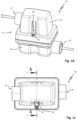
- Fig. 1a shows a first embodiment of an air filter 10 according to the invention with a filter housing 12 and with a flat air filter element 14 in a schematic exploded view.
- the filter housing 12 includes a housing pot 16 and a housing cover 18.
- An inlet of the filter housing for the air to be filtered is designated 20 and an outlet of the filter housing 12 is designated 22 .
- the flat air filter element 14 can be arranged between the housing pot 16 and the housing cover 18.
- the flat air filter element 14 includes a filter medium 24 and a sealing element 26, which is arranged circumferentially on the filter medium 24.
- the filter medium 24 consists of a cellulose material.
- the filter medium 24 is folded in a zigzag shape and is in the form of a bellows. Preferably, the filter medium 24 is cut to size before it is folded into the bellows.
- the filter medium has end edges 28 , which are preferably glued together in a waterproof manner, in particular end edge gluing is thus formed.
- the sealing element 26 is arranged here on the top side of the filter medium 18.
- the sealing element 26 can in particular be molded or foamed onto the filter medium 24.
- the sealing element 26 can consist, for example, of a polyurethane (PU), preferably a PU foam.
- the flat air filter element 14 has a recess 32 on its outer contour 30 .
- the recess 32 is formed here in the middle of a side edge 34 of the flat air filter element 14.
- the recess 30 is designed here as a curved indentation.
- the indentation here is rounded in a semicircle.
- the indentation can be concave on the flat air filter element 14 and point inwards.
- the recess 30 can be designed to be uniform on the filter medium 18 and the sealing element 20, so that the sealing element 20 projects over the filter medium 18 to the same extent everywhere.
- the housing pot 16 can have a circumferential free edge section 36 on the top side.
- the circumferential edge section 36 here forms a top end of an inner wall 38 of the housing pot 16.
- the inner wall 38 and the circumferential edge section 36 have a recess 40 on the top side here.
- the recess 40 can in particular correspond to the recess 32 of the flat air filter element 14 be carried out.
- a closure element 42 designed as a screw for the housing cover 18 and the housing pot 16 is arranged on the housing cover 18. The screw can protrude through the housing cover 18.
- a recess 44 for engaging the screw 40 is formed on the housing pot 16.
- the recess 44 is formed outside the free edge section 36 in the area of the recess 40 on the housing pot 14.
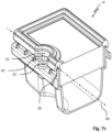
- Fig. 1b shows the air filter 10 according to Fig. 1a with closed filter housing 12 in a perspective view.
- the housing pot 16 and the housing cover 18 are clamped against each other here by the closure element 42.
- Fig. 1c the air filter 10 is shown in a top view.
- a recess 40 is also formed on the housing cover 16. The screw can be arranged on the outside in the area of the recess 40.
- Fig. 1d shows the air filter 10 according to Fig. 1a in a schematic cross section along the in Fig. 1c Cutting plane marked AA in the assembled state.
- the flat air filter element 14 is arranged in the filter housing 12.
- the sealing element 26 extends beyond the free edge section 36 of the housing pot 16 in a direction radial to the longitudinal axis 46 of the filter housing 12.
- the free edge section 36 of the housing pot 16 engages all around in a retaining groove 48 of the sealing element 26.
- the retaining groove 48 can also face the housing cover 18 according to an exemplary embodiment not shown in detail.
- the sealing element 26 of the flat air filter element 14 is therefore held circumferentially clamped between the housing pot 16, here its free edge section 36, and the housing cover 18 in an axial direction relative to the longitudinal axis 46 of the filter housing 12.
- the sealing element 26 can also be designed with its free end section 50 in such a way that it also lies sealingly against an annular collar 52 of the housing cover 18 in the radial direction.
- the sealing element 26 is therefore designed as a combined radial and axial sealing element.
- the annular collar 52 surrounds the housing pot 16 on the outside.
- the sealing element 26 of the flat air filter element 14 is circumferential due to the housing-side engagement in the retaining groove 48, especially in the area of the recess 32 in the radial direction reliably held in position between the two housing parts. This ensures a reliable sealing fit of the flat air filter element 14 in the filter housing 12 even during filter operation when there is a flow on the flat air filter element, ie a radially directed tensile load on the sealing element 26.
- a hook element can be formed on one of the housing parts 16, 18.
- the hook element preferably engages in a corresponding hook recess (hidden) in the other housing part 16, 18.
- Fig. 1e shows the air filter 10 in a horizontal section along the in Fig. 1d Cutting plane marked BB.
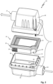
- FIG. 2 shows a second embodiment of an air filter 10 with a flat air filter element 12 in an exploded view of its parts.
- the air filter 10 is different from that mentioned above Figures 1a to 1e explained air filter 10 essentially in that the recess 32 is formed in a corner region 54 of the flat air filter element 14.
- the recess 32 can in particular be designed as an inwardly curved, concave indentation of the outer contour 30 of the flat air filter element 14.
- a screw can be arranged in the area of the recess 30 as a closure element 42.
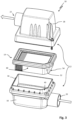
- Fig. 3 shows a third embodiment of an air filter 10 in an exploded view of its parts.
- the structure of the third embodiment essentially corresponds to the second embodiment Fig. 2 .
- a recess 30 on the corner region 54 of the flat air filter element 14 is designed here as a chamfer.
- the edge section 36 of the housing pot 16 can have a recess 40 which is adapted to the shape of the chamfer.
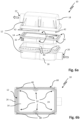
- Fig. 4a shows a fourth embodiment of an air filter 10 in an exploded view.
- a tension spring is provided here as a closure element 42.
- the recess 32 is formed centrally on a side edge 34 of the flat air filter element 14.
- the recess 32 can be designed to be wider than it is deep, in particular at least twice as wide as it is deep.
- Fig. 4b shows the air filter 10 according to Fig. 4a in a cross-sectional view at the level of the recess 32 and the tension spring.
- the tension spring encompasses a lateral projection 56 of the housing pot 16 and the annular collar 52 of the housing cover 18.
- the tension spring can be elastically stretched. As a result, the housing pot 16 and the housing cover 18 can be clamped against each other.
- the sealing element 20 of the flat air filter element 14 is clamped all around between the housing pot 16 and the housing cover 18.
- the sealing element 20 has the retaining groove 48, into which the housing pot 16 engages with its free edge section.
- Fig. 5 shows a fifth embodiment of an air filter 10 in an exploded view, in which a tension spring serves as a closure element 42.
- the recess 32 of the flat air filter element 14 is formed in a corner region 54.
- the recess 32 can be designed with a parallel offset to a side edge 34 of the flat air filter element 14.
- the tension spring can be guided along the recess 32 to close the housing pot 16 with the housing cover 18. This can prevent the closure element 42 from protruding laterally over an outer edge 58 of the housing cover 18.
- Fig. 6a shows a sixth embodiment of an air filter 10 in which the flat air filter element 14 is designed with several, here for example six, recesses 32.
- the recesses 32 can be formed in corner areas 54 and on side edges 34, for example in the middle.
- the air filter 10 can have a plurality of closure elements 42.
- the closure elements 42 can be designed in the form of screws or tension springs or the like.
- Fig. 6b shows the air filter 10 according to Fig. 6a in a schematic top view with the housing cover removed.
- the closure elements 42 are arranged in the area of the recesses 32.
- the closure elements 42 are thus secured by a sealing element 26 of the flat air filter element 14 in the area of the recesses 32 embraced.
- a substantially rectangular outline or outer shape 60 of the air filter 10 can thus be realized when viewed from above, with the flat air filter element 14 with its sealing element 26 and the filter medium 24 reaching close to the outer shape 60.
- the sealing element 20 can be arranged in areas between the closure elements 42 in order to increase a filter area of the filter medium 18.
- Fig. 7a shows a top view of a seventh embodiment of an air filter 10 with a closure element 42, which is arranged in the area of a recess 40 or a recess 32.
- this embodiment can, for example, correspond to the embodiment of the air filter 10 Fig. 1a , especially according to the presentation of the Fig. 1c , are equivalent to.
- the outer contour 30 along the filter medium 24 ( Fig. 1a ) hence the course of the front edges 28 ( Fig. 1a ), shown.
- an edge 64 of the air filter 10 can be seen.
- Fig. 7b shows an area 62 with the recess 32 of the air filter 10 Fig. 7a in an enlarged view.
- the recess 32 then projects into the flat air filter element 14 with an engagement depth I 1 , measured as the distance from the innermost point in the radial direction of the outer contour 30 of the filter medium 24 to the outer contour 30 outside the area of the recess 32 ( Fig. 1a ) inside.
- the engagement depth I 1 is at least 10 mm or 10.5 mm, in particular approximately 10.8 mm.
- the center of the closure element 42 is spaced from this innermost point by a distance I 2 , in this exemplary embodiment approximately 15 mm.
- the innermost point in this exemplary embodiment is spaced from the edge 64 by a distance I 3 , in this exemplary embodiment approximately 22 mm.
- the closure element 42 can be seen along an imaginary linear continuation 66 of the sealing element, bridging the recess 32 and in particular also the recess 40 26, in particular as shown here, the sealing groove-shaped main sealing surface surrounding the housing edge.
- Fig. 8a shows an alternative flat air filter element 14 with a recess 32 located in an area 68 in a schematic top view, with the area 68 again in Fig. 8b is shown enlarged.
- the sealing element 26 adjoins a filter medium 24 of the flat air filter element 14 designed as a bellows.
- the filter medium 24 has a (in the Fig. 8b schematically shown) end edge gluing 72 , through which the individual folds of the bellows are connected to one another in a sealing manner.
- the end edge gluing 72 runs in an edge region of the filter medium 24, in particular at a distance from the end edges 28.
- the sealing element 26 is sealingly connected to the filter medium 24 by means of a seal connection contour 70 .
- the seal connection contour 70 encloses the filter medium 24 in a form-fitting seal. In addition, it towers over this on the pure side.
- the seal connection contour 70 is preferably made of foam material, for example polyurethane.
- seal connection contour 70, the end edge gluing 72 and, in this exemplary embodiment, also the end edges 28, especially in the area of the recess 32, run parallel to one another.
- the sealing element 26 and the end edges 28 also run parallel to one another.
- seal connection contour 70, the end edge gluing 72, the end edges 28 and the sealing element 26 run parallel to one another in the area of the recess 26.
- Fig. 8c shows a schematic representation of the course of a glue bead 74 on a (still) unfolded filter medium 24. For reasons of illustration, only a section, in particular an edge region, of the filter medium 24 is shown.
- the glue bead 74 runs, in particular unkinked, in the edge region of the filter medium 24. It essentially follows an end edge 76 of the filter medium 24, being offset, for example, in an inner region of the filter medium 24.
- the (unfolded) filter medium 24 has an indentation 78 , from which a recess 32 is later formed by folding.
- the indentation 78 is also surrounded by the glue bead 74. If the indentation 78 is ignored, a main direction 80 results along the front edge 76.
- a selected point 82 on the glue bead 74 shows Fig. 8c the tangential angle 84 resulting from the inclination of the tangent at point 82 to the main direction 80.
- the course of the glue bead 74 is selected such that the tangential angle 84 is flat.
- the tangential angle 84 is at most 45° but as a rule at most 30°.
- the course of the glue bead 74 is not parallel to the indentation.
- the individual folds can be used to form the front edge gluing 72 ( Fig. 8b ) can be connected to each other.
- the course and width of the glue bead 74 are selected in particular such that adjacent sections of the glue bead 74 at least partially overlap.
- the end edge gluing 72 is preferably at least in the area of the recess, preferably along the entire end faces of the flat air filter element, at a tangential angle 86 ( Fig. 8b ) of at most 45° to the main direction of the folded filter medium, ie running to the end face 28 of the folded filter medium.
Landscapes
- Engineering & Computer Science (AREA)
- Chemical & Material Sciences (AREA)
- Chemical Kinetics & Catalysis (AREA)
- Combustion & Propulsion (AREA)
- Mechanical Engineering (AREA)
- General Engineering & Computer Science (AREA)
- Manufacturing & Machinery (AREA)
- Filtering Of Dispersed Particles In Gases (AREA)
Claims (14)
- Filtre à air (10), notamment dans le conduit d'admission d'air d'un moteur à combustion interne, comprenant un boîtier de filtre (12) ayant un pot de boîtier (16) et ayant un couvercle de boîtier (18) ainsi qu'un élément de fermeture (42) permettant de fermer le boîtier de filtre (12); et un élément de filtre à air plat (14) ayant un milieu filtrant (24) en matériau cellulosique conçu en tant que soufflet de filtre plié en accordéon et qui porte un élément d'étanchéité (26) circonférentiel,l'élément d'étanchéité (26) et le milieu filtrant (24) présentant au moins un retrait (32) sur un contour extérieur (30) de l'élément de filtre à air plat (14),l'élément de filtre à air plat (14) étant maintenu par serrage de manière circonférentielle avec son élément d'étanchéité (26) entre le pot de boîtier (16) et le couvercle de boîtier (18) à l'état fermé du boîtier de filtre (12),une rainure d'arrêt (48) circonférentielle étant conçue sur l'élément d'étanchéité (26) pour l'engagement d'un composant de boîtier (16, 18) du boîtier de filtre (12) et le pot de boîtier (16) ou le couvercle de boîtier (18) s'engageant dans la rainure d'arrêt (48) de l'élément d'étanchéité (26),l'élément de fermeture (42) du boîtier de filtre (46) étant disposé dans la zone du retrait (32) le long ou essentiellement le long d'un prolongement linéaire imaginaire (66) de l'élément d'étanchéité (26), qui enjambe le retrait (32),le milieu filtrant (24) présentant des arêtes frontales (28) collés les uns aux autres sous la forme d'un collage des arêtes frontales (72),un contour de liaison d'étanchéité (70) de l'élément d'étanchéité (26) et le collage des arêtes frontales (72) s'étendant parallèlement l'un à l'autre dans la zone du retrait (32),et le collage des arêtes frontales (72) s'étendant à l'état plié, au moins dans la zone du retrait (32), sous un angle tangentiel (86) ne dépassant pas 45° par rapport à une direction principale (80) du milieu filtrant (24) non plié,la direction principale (80) résultant de la direction de l'arête frontale du milieu filtrant non plié en dehors du retrait (32).
- Filtre à air selon la revendication 1, caractérisé en ce que le retrait (32) est réalisé sur une section de coin (54) de l'élément de filtre à air plat (14), notamment sous forme d'un chanfrein.
- Filtre à air selon la revendication 1 ou 2, caractérisé en ce que le retrait (32) est réalisé, notamment au centre, sur une arête latérale (34) de l'élément de filtre à air plat (14).
- Filtre à air selon l'une quelconque des revendications précédentes, caractérisé en ce que le retrait (32) est réalisé en tant que concavité bombée de l'élément de filtre à air plat (14).
- Filtre à air selon l'une quelconque des revendications précédentes, caractérisé en ce que le retrait (32) présente une profondeur d'encastrement (I1) d'au moins 10 mm, de préférence d'au moins 10,5 mm.
- Filtre à air selon l'une quelconque des revendications précédentes, caractérisé en ce que le collage des arêtes frontales (72) en état plié s'étend le long de toutes les faces frontales de l'élément de filtre à air plat (14) sous un angle tangentiel (86) ne dépassant pas 45° par rapport à la direction principale (80) du milieu filtrant (24) non plié.
- Filtre à air selon l'une quelconque des revendications précédentes, caractérisé en ce que le contour de liaison d'étanchéité (70) de l'élément d'étanchéité (26) et le collage des arêtes frontales (72) s'étendent parallèlement l'un à l'autre le long de toutes les faces frontales de l'élément de filtre à air plat (14).
- Filtre à air selon l'une quelconque des revendications précédentes, caractérisé en ce que l'élément d'étanchéité (26) et les arêtes frontales (28) s'étendent parallèlement l'un à l'autre dans la zone du retrait (32), de préférence le long de toutes les faces frontales de l'élément de filtre à air plat (14).
- Filtre à air selon l'une quelconque des revendications précédentes, caractérisé en ce que l'élément d'étanchéité (26) et/ou les arêtes frontales (28) s'étendent parallèlement au collage des arêtes frontales (72) dans la zone du retrait (32), de préférence le long de toutes les faces frontales de l'élément de filtre à air plat (14).
- Filtre à air selon l'une quelconque des revendications précédentes, caractérisé en ce que l'élément d'étanchéité (26) est réalisé en polyuréthane, l'élément d'étanchéité (26) étant de préférence moulé par injection ou moussé sur l'élément de filtre à air plat (14).
- Filtre à air selon l'une quelconque des revendications précédentes, caractérisé en ce que l'élément de fermeture (42) est un ressort de rappel, une vis ou un autre élément de rappel.
- Filtre à air selon l'une quelconque des revendications précédentes, caractérisé en ce que, à l'opposé du retrait (32), le couvercle de boîtier (18) et le pot de boîtier (16) sont reliés l'un à l'autre par une charnière et un élément de rappel, notamment un ressort de rappel ou une vis, qui est disposé sur un côté du boîtier opposé au retrait (32) de l'élément de filtre à air plat (14).
- Filtre à air selon l'une quelconque des revendications précédentes, caractérisé en ce que le boîtier de filtre (12) présente plusieurs éléments de fermeture (42) et l'élément de filtre à air plat (14) présente un nombre de retraits (32) correspondant au nombre d'éléments de fermeture (42).
- Utilisation d'un élément de filtre à air plat (14) dans un filtre à air (10) selon l'une quelconque des revendications 1 à 13.
Applications Claiming Priority (2)
| Application Number | Priority Date | Filing Date | Title |
|---|---|---|---|
| DE102016005088 | 2016-04-27 | ||
| PCT/EP2017/059993 WO2017186820A1 (fr) | 2016-04-27 | 2017-04-26 | Élément filtre à air plat et filtre à air |
Publications (2)
| Publication Number | Publication Date |
|---|---|
| EP3449113A1 EP3449113A1 (fr) | 2019-03-06 |
| EP3449113B1 true EP3449113B1 (fr) | 2024-03-27 |
Family
ID=58707496
Family Applications (1)
| Application Number | Title | Priority Date | Filing Date |
|---|---|---|---|
| EP17723296.4A Active EP3449113B1 (fr) | 2016-04-27 | 2017-04-26 | Filtre à air avec élément de filtre à air plat |
Country Status (6)
| Country | Link |
|---|---|
| US (1) | US10662905B2 (fr) |
| EP (1) | EP3449113B1 (fr) |
| CN (1) | CN109072827B (fr) |
| BR (1) | BR112018068528B1 (fr) |
| DE (2) | DE112017002216A5 (fr) |
| WO (1) | WO2017186820A1 (fr) |
Families Citing this family (16)
| Publication number | Priority date | Publication date | Assignee | Title |
|---|---|---|---|---|
| US11020698B2 (en) | 2015-12-11 | 2021-06-01 | Cummins Filtration Ip, Inc. | Filter with variable cross-section axial seal |
| US11167234B2 (en) | 2016-03-18 | 2021-11-09 | Cummins Filtration Ip, Inc. | Interlocked stable filter assembly |
| DE102016004315A1 (de) * | 2016-04-12 | 2017-10-12 | Mann + Hummel Gmbh | Filteranordnung |
| DE102016013844A1 (de) * | 2016-11-22 | 2018-05-24 | Mann + Hummel Gmbh | Rundfilterelement mit längs gestreckter Querschnittsform |
| US11724220B2 (en) | 2017-02-21 | 2023-08-15 | Cummins Filtration Ip, Inc. | Undulated interlocking housing-endplate interface geometry |
| CN115155166B (zh) * | 2017-03-16 | 2024-01-26 | 康明斯滤清系统知识产权公司 | 过滤密封系统 |
| MX2020001477A (es) | 2017-08-09 | 2020-03-20 | Donaldson Co Inc | Cartuchos filtrantes, conjuntos de purificador de aire, carcasas, caracteristicas, componentes, metodos. |
| CN115591330A (zh) * | 2018-06-05 | 2023-01-13 | 上海欧菲滤清器有限公司(Cn) | 板式空气过滤器、抽屉元件、以及空气过滤组件 |
| USD1002792S1 (en) | 2019-02-05 | 2023-10-24 | Donaldson Company, Inc. | Filter cartridge |
| WO2021108372A1 (fr) * | 2019-11-25 | 2021-06-03 | Abc Technologies Inc. | Appareil épurateur d'air à élément de fixation |
| WO2021163027A1 (fr) | 2020-02-11 | 2021-08-19 | Cummins Filtration Inc. | Système de filtration de carburant avancé avec conception de joint d'étanchéité de cartouche à interverrouillage |
| DE102021117356B4 (de) | 2020-07-16 | 2024-01-11 | Dräger Safety AG & Co. KGaA | Gefaltetes Filterelement sowie dessen Verwendung, Filter sowie Verfahren zur Herstellung des Filterelements und des Filters |
| EP4188579B1 (fr) | 2020-07-31 | 2024-07-10 | MANN+HUMMEL GmbH | Élément filtrant comprenant un milieu filtrant plié en zigzag à liaison d'extrémité discontinue, et son procédé de production |
| US11992800B2 (en) | 2020-11-24 | 2024-05-28 | Cummins Filtration Inc. | Arched air filter |
| CN114017213A (zh) * | 2021-12-06 | 2022-02-08 | 江门市大长江集团有限公司 | 一种空气滤清器及摩托车 |
| DE102024101445A1 (de) * | 2024-01-18 | 2025-07-24 | Mann+Hummel Gmbh | Filterelement |
Citations (1)
| Publication number | Priority date | Publication date | Assignee | Title |
|---|---|---|---|---|
| WO2017102287A1 (fr) * | 2015-12-16 | 2017-06-22 | Mann+Hummel Gmbh | Soufflet de filtration et élément filtre |
Family Cites Families (38)
| Publication number | Priority date | Publication date | Assignee | Title |
|---|---|---|---|---|
| DE2137309C3 (de) | 1971-07-26 | 1979-08-02 | Purolator Filter Gmbh, 7110 Oehringen | Filter mit einem aus einem Zickzack förmig gefalteten, mit thermoplastischem Kunstharz imprägnierten Filterpapierstreifen bestehenden Faltblock |
| DE4328846C2 (de) | 1993-08-27 | 1999-05-20 | Mann & Hummel Filter | Verfahren zur Herstellung eines Filtereinsatzes und durch dieses Verfahren hergestellter Filtereinsatz |
| JP3299622B2 (ja) * | 1994-03-11 | 2002-07-08 | 豊田紡織株式会社 | エアクリーナ装置 |
| DE4435532A1 (de) | 1994-10-05 | 1996-04-11 | Mann & Hummel Filter | Verfahren zur Herstellung von Filtern |
| IN189834B (fr) | 1997-04-18 | 2003-04-26 | Mann & Hummel Filter | |
| DE19824506C1 (de) | 1998-06-02 | 1999-07-01 | Freudenberg Carl Fa | Filterelement und Verfahren zu seiner Herstellung |
| DE19859854A1 (de) | 1998-12-23 | 2000-06-29 | Mann & Hummel Filter | Filter mit einem durch mindestens eine Verstärkung verstärkten Gehäuse |
| DE20310833U1 (de) | 2003-07-14 | 2004-11-18 | B & S Industrieservice Gmbh | Filtereinsatz zum Einbau in einen Strömungskanal |
| DE102004002293A1 (de) | 2004-01-16 | 2005-07-14 | Audi Ag | Luftfilter |
| JP4509012B2 (ja) * | 2005-12-06 | 2010-07-21 | 本田技研工業株式会社 | エアクリーナ装置及びその製造方法 |
| DE102007005613A1 (de) | 2006-02-09 | 2007-08-30 | Mann + Hummel Gmbh | Filtermatte |
| CN200961548Y (zh) * | 2006-10-20 | 2007-10-17 | 重庆长安汽车股份有限公司 | 一种汽车空滤器 |
| WO2008051936A2 (fr) | 2006-10-20 | 2008-05-02 | Cummins Filtration Ip | Appareil, système et procédé pour fabriquer des panneaux filtrants mis en forme de maniére irrégulière |
| ATE512705T1 (de) | 2007-07-27 | 2011-07-15 | Mann & Hummel Gmbh | Luftfilter, insbesondere für verbrennungsmotoren in kraftfahrzeugen |
| DE202008015078U1 (de) | 2008-11-13 | 2010-04-08 | Mann+Hummel Gmbh | Luftfiltereinsatz |
| DE202009000969U1 (de) | 2009-01-26 | 2010-07-01 | Mann+Hummel Gmbh | Filterelement |
| DE202009002178U1 (de) | 2009-02-16 | 2010-07-15 | Mann+Hummel Gmbh | Filtereinrichtung zur Filtration gasförmiger Fluide |
| JP5656430B2 (ja) | 2010-03-23 | 2015-01-21 | 本田技研工業株式会社 | エアクリーナ装置 |
| DE102010053200A1 (de) | 2010-12-03 | 2012-06-06 | Carl Freudenberg Kg | Zugeschnittenes Filterelement mit fünfeckigem Faltenbalg |
| CN103282638B (zh) | 2011-01-11 | 2017-02-08 | 曼·胡默尔有限公司 | 空气清洁器组件和空气过滤元件 |
| DE102011078057A1 (de) * | 2011-06-24 | 2013-01-10 | Mahle International Gmbh | Plattenfilterelement |
| DE112013000555A5 (de) * | 2012-01-13 | 2014-09-18 | Mann + Hummel Gmbh | Luftfilterelement mit Haltegeometrie |
| DE102012005530A1 (de) | 2012-03-21 | 2013-09-26 | Mann+Hummel Gmbh | Verfahren zur Herstellung eines mit einem Dichtungsteil versehenen Filterelements |
| JP2013227965A (ja) * | 2012-03-28 | 2013-11-07 | Yamaha Motor Co Ltd | 鞍乗型車両 |
| DE102012013470A1 (de) | 2012-07-09 | 2014-05-08 | Mann + Hummel Gmbh | Verfahren und Vorrichtung zum Fertigen von Filterelementen sowie Filterelement |
| CN203374400U (zh) * | 2013-07-03 | 2014-01-01 | 美嘉帕拉斯特汽车零部件(上海)有限公司 | 车辆空滤盒 |
| DE102014015907B4 (de) | 2013-11-20 | 2025-05-28 | Mann+Hummel Gmbh | Vorrichtung und Verfahren zur Herstellung eines Filterbalges eines Flachfilterelements für Fluide sowie ein Flachfilterelement für Fluide mit einem Faltenbalg |
| WO2015074806A1 (fr) | 2013-11-20 | 2015-05-28 | Mann+Hummel Gmbh | Élément de filtration équipé d'un soufflet de filtration |
| DE102013019327B4 (de) | 2013-11-20 | 2023-06-01 | Mann+Hummel Gmbh | Filterelement mit Filterbalg und Verwendung des Filterelements |
| DE102014016672A1 (de) | 2013-11-28 | 2015-05-28 | Mann+Hummel Gmbh | Filterelement mit Filterbalg |
| CN106573184B (zh) | 2014-07-25 | 2019-07-19 | 康明斯过滤Ip公司 | 具有变化的过滤介质包特性的过滤元件 |
| DE102014013280A1 (de) | 2014-09-12 | 2016-03-17 | Mann + Hummel Gmbh | Filtereinrichtung zur Gasfiltration sowie Filterelement für eine Filtereinrichtung zur Gasfiltration |
| DE102014013278A1 (de) | 2014-09-12 | 2016-03-17 | Mann + Hummel Gmbh | Plattenförmiges Filterelement zur Gasfiltration |
| CN105413321A (zh) * | 2014-09-12 | 2016-03-23 | 曼·胡默尔有限公司 | 用于气体过滤用的过滤装置的过滤元件 |
| DE102015011660A1 (de) | 2014-09-12 | 2016-03-17 | Mann + Hummel Gmbh | Filtereinrichtung zur Gasfiltration |
| DE102015016236A1 (de) * | 2015-01-23 | 2016-07-28 | Mann+Hummel Gmbh | Filterelement mit mehreren übereinanderliegenden Einzelblättern |
| DE102015005565A1 (de) | 2015-05-04 | 2016-11-10 | Mann + Hummel Gmbh | Verfahren zum Herstellen von Filterbälgen |
| DE102015226754A1 (de) * | 2015-12-28 | 2017-06-29 | Mahle International Gmbh | Filtereinrichtung |
-
2017
- 2017-04-26 WO PCT/EP2017/059993 patent/WO2017186820A1/fr not_active Ceased
- 2017-04-26 DE DE112017002216.9T patent/DE112017002216A5/de active Pending
- 2017-04-26 CN CN201780026185.5A patent/CN109072827B/zh active Active
- 2017-04-26 DE DE102017003997.6A patent/DE102017003997A1/de not_active Withdrawn
- 2017-04-26 EP EP17723296.4A patent/EP3449113B1/fr active Active
- 2017-04-26 BR BR112018068528-3A patent/BR112018068528B1/pt active IP Right Grant
-
2018
- 2018-10-28 US US16/172,821 patent/US10662905B2/en active Active
Patent Citations (1)
| Publication number | Priority date | Publication date | Assignee | Title |
|---|---|---|---|---|
| WO2017102287A1 (fr) * | 2015-12-16 | 2017-06-22 | Mann+Hummel Gmbh | Soufflet de filtration et élément filtre |
Also Published As
| Publication number | Publication date |
|---|---|
| EP3449113A1 (fr) | 2019-03-06 |
| CN109072827A (zh) | 2018-12-21 |
| US20190063380A1 (en) | 2019-02-28 |
| DE112017002216A5 (de) | 2019-01-10 |
| DE102017003997A1 (de) | 2017-11-02 |
| BR112018068528B1 (pt) | 2022-12-06 |
| US10662905B2 (en) | 2020-05-26 |
| CN109072827B (zh) | 2021-06-04 |
| WO2017186820A1 (fr) | 2017-11-02 |
| BR112018068528A2 (pt) | 2019-01-29 |
Similar Documents
| Publication | Publication Date | Title |
|---|---|---|
| WO2017186820A1 (fr) | Élément filtre à air plat et filtre à air | |
| EP2802401B1 (fr) | Elément filtrant à géométrie de retenue destiné à un filtre à air | |
| EP2802400B1 (fr) | Élément filtre à air à géométrie de retenue | |
| DE102007024287B4 (de) | Gas-Filtereinsatz und Gas-Filter enthaltend diesen | |
| EP2802403B1 (fr) | Élément filtre à air et filtre à air | |
| DE102012019320B4 (de) | Stützeinrichtung eines Filters, Flachfilterelement eines Filters und Filter | |
| EP2802402B1 (fr) | Élément de filtre à air à géométrie de retenue particulière | |
| EP2135662B1 (fr) | Elément filtrant compressible avec des capuchons d'extrémité inclinés les uns vers les autres | |
| WO2015074806A1 (fr) | Élément de filtration équipé d'un soufflet de filtration | |
| WO2015193341A2 (fr) | Filtre et cartouche filtrante | |
| EP3411129A1 (fr) | Élément filtrant, cadre d'un élément filtrant, soufflet filtrant d'un élément filtrant, boîtier de filtre et filtre | |
| DE102014009026A1 (de) | Filterelement mit wenigstens einem Führungssteg, Filter mit einem Filterelement und Filtergehäuse eines Filters | |
| EP2981700B1 (fr) | Élément de filtration d'air | |
| DE102010025971B4 (de) | Filter zur Filtrierung von Fluiden und Filtereinsatz | |
| WO2017144289A1 (fr) | Élément filtrant, en particulier pour la filtration de gaz | |
| EP3980158B1 (fr) | Élément filtrant et système de filtre | |
| WO2017133798A1 (fr) | Boîtier de filtre et filtre | |
| EP1736227B1 (fr) | Système d'étanchéité d'un filtre | |
| WO2017144287A1 (fr) | Élément filtrant, en particulier pour la filtration de gaz | |
| DE102014008699B4 (de) | Filterelement mit prismatischer Grundform und Filter | |
| DE102014008701B4 (de) | Filter mit variierbarer Abströmrichtung | |
| DE202014004897U1 (de) | Filter mit variierbarer Abströmrichtung | |
| EP4028143B1 (fr) | Élément d'épuration de fluide d'un système d'épuration de fluide conçu pour épurer un fluide liquide, système d'épuration de fluide et élément d'étanchéité d'un élément d'épuration de fluide | |
| DE102014008702B4 (de) | Filter mit schräger Dichtungsebene | |
| DE102015007653A1 (de) | Filterelement mit prismatischer Grundform |
Legal Events
| Date | Code | Title | Description |
|---|---|---|---|
| STAA | Information on the status of an ep patent application or granted ep patent |
Free format text: STATUS: UNKNOWN |
|
| STAA | Information on the status of an ep patent application or granted ep patent |
Free format text: STATUS: THE INTERNATIONAL PUBLICATION HAS BEEN MADE |
|
| PUAI | Public reference made under article 153(3) epc to a published international application that has entered the european phase |
Free format text: ORIGINAL CODE: 0009012 |
|
| STAA | Information on the status of an ep patent application or granted ep patent |
Free format text: STATUS: REQUEST FOR EXAMINATION WAS MADE |
|
| 17P | Request for examination filed |
Effective date: 20181009 |
|
| AK | Designated contracting states |
Kind code of ref document: A1 Designated state(s): AL AT BE BG CH CY CZ DE DK EE ES FI FR GB GR HR HU IE IS IT LI LT LU LV MC MK MT NL NO PL PT RO RS SE SI SK SM TR |
|
| AX | Request for extension of the european patent |
Extension state: BA ME |
|
| DAV | Request for validation of the european patent (deleted) | ||
| DAX | Request for extension of the european patent (deleted) | ||
| STAA | Information on the status of an ep patent application or granted ep patent |
Free format text: STATUS: EXAMINATION IS IN PROGRESS |
|
| 17Q | First examination report despatched |
Effective date: 20200330 |
|
| RAP3 | Party data changed (applicant data changed or rights of an application transferred) |
Owner name: MANN+HUMMEL GMBH |
|
| GRAP | Despatch of communication of intention to grant a patent |
Free format text: ORIGINAL CODE: EPIDOSNIGR1 |
|
| STAA | Information on the status of an ep patent application or granted ep patent |
Free format text: STATUS: GRANT OF PATENT IS INTENDED |
|
| RIC1 | Information provided on ipc code assigned before grant |
Ipc: B01D 46/00 20060101ALI20231020BHEP Ipc: B01D 46/42 20060101ALI20231020BHEP Ipc: B01D 46/10 20060101ALI20231020BHEP Ipc: F02M 35/024 20060101ALI20231020BHEP Ipc: F02M 35/02 20060101AFI20231020BHEP |
|
| INTG | Intention to grant announced |
Effective date: 20231108 |
|
| GRAS | Grant fee paid |
Free format text: ORIGINAL CODE: EPIDOSNIGR3 |
|
| GRAA | (expected) grant |
Free format text: ORIGINAL CODE: 0009210 |
|
| STAA | Information on the status of an ep patent application or granted ep patent |
Free format text: STATUS: THE PATENT HAS BEEN GRANTED |
|
| AK | Designated contracting states |
Kind code of ref document: B1 Designated state(s): AL AT BE BG CH CY CZ DE DK EE ES FI FR GB GR HR HU IE IS IT LI LT LU LV MC MK MT NL NO PL PT RO RS SE SI SK SM TR |
|
| REG | Reference to a national code |
Ref country code: GB Ref legal event code: FG4D Free format text: NOT ENGLISH |
|
| REG | Reference to a national code |
Ref country code: CH Ref legal event code: EP |
|
| REG | Reference to a national code |
Ref country code: DE Ref legal event code: R096 Ref document number: 502017015964 Country of ref document: DE |
|
| REG | Reference to a national code |
Ref country code: IE Ref legal event code: FG4D Free format text: LANGUAGE OF EP DOCUMENT: GERMAN |
|
| P01 | Opt-out of the competence of the unified patent court (upc) registered |
Effective date: 20240321 |
|
| PG25 | Lapsed in a contracting state [announced via postgrant information from national office to epo] |
Ref country code: LT Free format text: LAPSE BECAUSE OF FAILURE TO SUBMIT A TRANSLATION OF THE DESCRIPTION OR TO PAY THE FEE WITHIN THE PRESCRIBED TIME-LIMIT Effective date: 20240327 |
|
| REG | Reference to a national code |
Ref country code: LT Ref legal event code: MG9D |
|
| PG25 | Lapsed in a contracting state [announced via postgrant information from national office to epo] |
Ref country code: GR Free format text: LAPSE BECAUSE OF FAILURE TO SUBMIT A TRANSLATION OF THE DESCRIPTION OR TO PAY THE FEE WITHIN THE PRESCRIBED TIME-LIMIT Effective date: 20240628 |
|
| PG25 | Lapsed in a contracting state [announced via postgrant information from national office to epo] |
Ref country code: RS Free format text: LAPSE BECAUSE OF FAILURE TO SUBMIT A TRANSLATION OF THE DESCRIPTION OR TO PAY THE FEE WITHIN THE PRESCRIBED TIME-LIMIT Effective date: 20240627 Ref country code: HR Free format text: LAPSE BECAUSE OF FAILURE TO SUBMIT A TRANSLATION OF THE DESCRIPTION OR TO PAY THE FEE WITHIN THE PRESCRIBED TIME-LIMIT Effective date: 20240327 |
|
| PG25 | Lapsed in a contracting state [announced via postgrant information from national office to epo] |
Ref country code: RS Free format text: LAPSE BECAUSE OF FAILURE TO SUBMIT A TRANSLATION OF THE DESCRIPTION OR TO PAY THE FEE WITHIN THE PRESCRIBED TIME-LIMIT Effective date: 20240627 Ref country code: NO Free format text: LAPSE BECAUSE OF FAILURE TO SUBMIT A TRANSLATION OF THE DESCRIPTION OR TO PAY THE FEE WITHIN THE PRESCRIBED TIME-LIMIT Effective date: 20240627 Ref country code: LT Free format text: LAPSE BECAUSE OF FAILURE TO SUBMIT A TRANSLATION OF THE DESCRIPTION OR TO PAY THE FEE WITHIN THE PRESCRIBED TIME-LIMIT Effective date: 20240327 Ref country code: HR Free format text: LAPSE BECAUSE OF FAILURE TO SUBMIT A TRANSLATION OF THE DESCRIPTION OR TO PAY THE FEE WITHIN THE PRESCRIBED TIME-LIMIT Effective date: 20240327 Ref country code: GR Free format text: LAPSE BECAUSE OF FAILURE TO SUBMIT A TRANSLATION OF THE DESCRIPTION OR TO PAY THE FEE WITHIN THE PRESCRIBED TIME-LIMIT Effective date: 20240628 Ref country code: FI Free format text: LAPSE BECAUSE OF FAILURE TO SUBMIT A TRANSLATION OF THE DESCRIPTION OR TO PAY THE FEE WITHIN THE PRESCRIBED TIME-LIMIT Effective date: 20240327 Ref country code: BG Free format text: LAPSE BECAUSE OF FAILURE TO SUBMIT A TRANSLATION OF THE DESCRIPTION OR TO PAY THE FEE WITHIN THE PRESCRIBED TIME-LIMIT Effective date: 20240327 |
|
| REG | Reference to a national code |
Ref country code: NL Ref legal event code: MP Effective date: 20240327 |
|
| PG25 | Lapsed in a contracting state [announced via postgrant information from national office to epo] |
Ref country code: SE Free format text: LAPSE BECAUSE OF FAILURE TO SUBMIT A TRANSLATION OF THE DESCRIPTION OR TO PAY THE FEE WITHIN THE PRESCRIBED TIME-LIMIT Effective date: 20240327 Ref country code: LV Free format text: LAPSE BECAUSE OF FAILURE TO SUBMIT A TRANSLATION OF THE DESCRIPTION OR TO PAY THE FEE WITHIN THE PRESCRIBED TIME-LIMIT Effective date: 20240327 |
|
| PG25 | Lapsed in a contracting state [announced via postgrant information from national office to epo] |
Ref country code: NL Free format text: LAPSE BECAUSE OF FAILURE TO SUBMIT A TRANSLATION OF THE DESCRIPTION OR TO PAY THE FEE WITHIN THE PRESCRIBED TIME-LIMIT Effective date: 20240327 |
|
| PG25 | Lapsed in a contracting state [announced via postgrant information from national office to epo] |
Ref country code: NL Free format text: LAPSE BECAUSE OF FAILURE TO SUBMIT A TRANSLATION OF THE DESCRIPTION OR TO PAY THE FEE WITHIN THE PRESCRIBED TIME-LIMIT Effective date: 20240327 |
|
| PG25 | Lapsed in a contracting state [announced via postgrant information from national office to epo] |
Ref country code: IS Free format text: LAPSE BECAUSE OF FAILURE TO SUBMIT A TRANSLATION OF THE DESCRIPTION OR TO PAY THE FEE WITHIN THE PRESCRIBED TIME-LIMIT Effective date: 20240727 |
|
| PG25 | Lapsed in a contracting state [announced via postgrant information from national office to epo] |
Ref country code: SM Free format text: LAPSE BECAUSE OF FAILURE TO SUBMIT A TRANSLATION OF THE DESCRIPTION OR TO PAY THE FEE WITHIN THE PRESCRIBED TIME-LIMIT Effective date: 20240327 Ref country code: PT Free format text: LAPSE BECAUSE OF FAILURE TO SUBMIT A TRANSLATION OF THE DESCRIPTION OR TO PAY THE FEE WITHIN THE PRESCRIBED TIME-LIMIT Effective date: 20240729 |
|
| PG25 | Lapsed in a contracting state [announced via postgrant information from national office to epo] |
Ref country code: ES Free format text: LAPSE BECAUSE OF FAILURE TO SUBMIT A TRANSLATION OF THE DESCRIPTION OR TO PAY THE FEE WITHIN THE PRESCRIBED TIME-LIMIT Effective date: 20240327 |
|
| PG25 | Lapsed in a contracting state [announced via postgrant information from national office to epo] |
Ref country code: CZ Free format text: LAPSE BECAUSE OF FAILURE TO SUBMIT A TRANSLATION OF THE DESCRIPTION OR TO PAY THE FEE WITHIN THE PRESCRIBED TIME-LIMIT Effective date: 20240327 Ref country code: EE Free format text: LAPSE BECAUSE OF FAILURE TO SUBMIT A TRANSLATION OF THE DESCRIPTION OR TO PAY THE FEE WITHIN THE PRESCRIBED TIME-LIMIT Effective date: 20240327 |
|
| PG25 | Lapsed in a contracting state [announced via postgrant information from national office to epo] |
Ref country code: PL Free format text: LAPSE BECAUSE OF FAILURE TO SUBMIT A TRANSLATION OF THE DESCRIPTION OR TO PAY THE FEE WITHIN THE PRESCRIBED TIME-LIMIT Effective date: 20240327 |
|
| PG25 | Lapsed in a contracting state [announced via postgrant information from national office to epo] |
Ref country code: SK Free format text: LAPSE BECAUSE OF FAILURE TO SUBMIT A TRANSLATION OF THE DESCRIPTION OR TO PAY THE FEE WITHIN THE PRESCRIBED TIME-LIMIT Effective date: 20240327 |
|
| PG25 | Lapsed in a contracting state [announced via postgrant information from national office to epo] |
Ref country code: SM Free format text: LAPSE BECAUSE OF FAILURE TO SUBMIT A TRANSLATION OF THE DESCRIPTION OR TO PAY THE FEE WITHIN THE PRESCRIBED TIME-LIMIT Effective date: 20240327 Ref country code: SK Free format text: LAPSE BECAUSE OF FAILURE TO SUBMIT A TRANSLATION OF THE DESCRIPTION OR TO PAY THE FEE WITHIN THE PRESCRIBED TIME-LIMIT Effective date: 20240327 Ref country code: PT Free format text: LAPSE BECAUSE OF FAILURE TO SUBMIT A TRANSLATION OF THE DESCRIPTION OR TO PAY THE FEE WITHIN THE PRESCRIBED TIME-LIMIT Effective date: 20240729 Ref country code: PL Free format text: LAPSE BECAUSE OF FAILURE TO SUBMIT A TRANSLATION OF THE DESCRIPTION OR TO PAY THE FEE WITHIN THE PRESCRIBED TIME-LIMIT Effective date: 20240327 Ref country code: IS Free format text: LAPSE BECAUSE OF FAILURE TO SUBMIT A TRANSLATION OF THE DESCRIPTION OR TO PAY THE FEE WITHIN THE PRESCRIBED TIME-LIMIT Effective date: 20240727 Ref country code: ES Free format text: LAPSE BECAUSE OF FAILURE TO SUBMIT A TRANSLATION OF THE DESCRIPTION OR TO PAY THE FEE WITHIN THE PRESCRIBED TIME-LIMIT Effective date: 20240327 Ref country code: EE Free format text: LAPSE BECAUSE OF FAILURE TO SUBMIT A TRANSLATION OF THE DESCRIPTION OR TO PAY THE FEE WITHIN THE PRESCRIBED TIME-LIMIT Effective date: 20240327 Ref country code: CZ Free format text: LAPSE BECAUSE OF FAILURE TO SUBMIT A TRANSLATION OF THE DESCRIPTION OR TO PAY THE FEE WITHIN THE PRESCRIBED TIME-LIMIT Effective date: 20240327 |
|
| REG | Reference to a national code |
Ref country code: CH Ref legal event code: PL |
|
| PG25 | Lapsed in a contracting state [announced via postgrant information from national office to epo] |
Ref country code: LU Free format text: LAPSE BECAUSE OF NON-PAYMENT OF DUE FEES Effective date: 20240426 |
|
| REG | Reference to a national code |
Ref country code: BE Ref legal event code: MM Effective date: 20240430 |
|
| PG25 | Lapsed in a contracting state [announced via postgrant information from national office to epo] |
Ref country code: LU Free format text: LAPSE BECAUSE OF NON-PAYMENT OF DUE FEES Effective date: 20240426 |
|
| REG | Reference to a national code |
Ref country code: DE Ref legal event code: R097 Ref document number: 502017015964 Country of ref document: DE |
|
| PG25 | Lapsed in a contracting state [announced via postgrant information from national office to epo] |
Ref country code: MC Free format text: LAPSE BECAUSE OF FAILURE TO SUBMIT A TRANSLATION OF THE DESCRIPTION OR TO PAY THE FEE WITHIN THE PRESCRIBED TIME-LIMIT Effective date: 20240327 |
|
| PG25 | Lapsed in a contracting state [announced via postgrant information from national office to epo] |
Ref country code: DK Free format text: LAPSE BECAUSE OF FAILURE TO SUBMIT A TRANSLATION OF THE DESCRIPTION OR TO PAY THE FEE WITHIN THE PRESCRIBED TIME-LIMIT Effective date: 20240327 |
|
| PG25 | Lapsed in a contracting state [announced via postgrant information from national office to epo] |
Ref country code: BE Free format text: LAPSE BECAUSE OF NON-PAYMENT OF DUE FEES Effective date: 20240430 |
|
| PG25 | Lapsed in a contracting state [announced via postgrant information from national office to epo] |
Ref country code: MC Free format text: LAPSE BECAUSE OF FAILURE TO SUBMIT A TRANSLATION OF THE DESCRIPTION OR TO PAY THE FEE WITHIN THE PRESCRIBED TIME-LIMIT Effective date: 20240327 Ref country code: DK Free format text: LAPSE BECAUSE OF FAILURE TO SUBMIT A TRANSLATION OF THE DESCRIPTION OR TO PAY THE FEE WITHIN THE PRESCRIBED TIME-LIMIT Effective date: 20240327 Ref country code: BE Free format text: LAPSE BECAUSE OF NON-PAYMENT OF DUE FEES Effective date: 20240430 Ref country code: CH Free format text: LAPSE BECAUSE OF NON-PAYMENT OF DUE FEES Effective date: 20240430 |
|
| PLBE | No opposition filed within time limit |
Free format text: ORIGINAL CODE: 0009261 |
|
| STAA | Information on the status of an ep patent application or granted ep patent |
Free format text: STATUS: NO OPPOSITION FILED WITHIN TIME LIMIT |
|
| 26N | No opposition filed |
Effective date: 20250103 |
|
| PG25 | Lapsed in a contracting state [announced via postgrant information from national office to epo] |
Ref country code: IE Free format text: LAPSE BECAUSE OF NON-PAYMENT OF DUE FEES Effective date: 20240426 |
|
| PG25 | Lapsed in a contracting state [announced via postgrant information from national office to epo] |
Ref country code: SI Free format text: LAPSE BECAUSE OF FAILURE TO SUBMIT A TRANSLATION OF THE DESCRIPTION OR TO PAY THE FEE WITHIN THE PRESCRIBED TIME-LIMIT Effective date: 20240327 |
|
| REG | Reference to a national code |
Ref country code: AT Ref legal event code: MM01 Ref document number: 1670133 Country of ref document: AT Kind code of ref document: T Effective date: 20240426 |
|
| PGFP | Annual fee paid to national office [announced via postgrant information from national office to epo] |
Ref country code: DE Payment date: 20250422 Year of fee payment: 9 |
|
| PGFP | Annual fee paid to national office [announced via postgrant information from national office to epo] |
Ref country code: GB Payment date: 20250423 Year of fee payment: 9 |
|
| PGFP | Annual fee paid to national office [announced via postgrant information from national office to epo] |
Ref country code: IT Payment date: 20250424 Year of fee payment: 9 |
|
| PGFP | Annual fee paid to national office [announced via postgrant information from national office to epo] |
Ref country code: FR Payment date: 20250425 Year of fee payment: 9 |
|
| PG25 | Lapsed in a contracting state [announced via postgrant information from national office to epo] |
Ref country code: AT Free format text: LAPSE BECAUSE OF NON-PAYMENT OF DUE FEES Effective date: 20240426 |
|
| PGFP | Annual fee paid to national office [announced via postgrant information from national office to epo] |
Ref country code: RO Payment date: 20250424 Year of fee payment: 9 |
|
| PG25 | Lapsed in a contracting state [announced via postgrant information from national office to epo] |
Ref country code: CY Free format text: LAPSE BECAUSE OF FAILURE TO SUBMIT A TRANSLATION OF THE DESCRIPTION OR TO PAY THE FEE WITHIN THE PRESCRIBED TIME-LIMIT; INVALID AB INITIO Effective date: 20170426 |
|
| PG25 | Lapsed in a contracting state [announced via postgrant information from national office to epo] |
Ref country code: HU Free format text: LAPSE BECAUSE OF FAILURE TO SUBMIT A TRANSLATION OF THE DESCRIPTION OR TO PAY THE FEE WITHIN THE PRESCRIBED TIME-LIMIT; INVALID AB INITIO Effective date: 20170426 |