EP3449121B1 - Procédé pour plier des pales éoliennes et procédé pour ouvrir des pales éoliennes pour une turbine éolienne ayant des pales pliables - Google Patents
Procédé pour plier des pales éoliennes et procédé pour ouvrir des pales éoliennes pour une turbine éolienne ayant des pales pliables Download PDFInfo
- Publication number
- EP3449121B1 EP3449121B1 EP16736254.0A EP16736254A EP3449121B1 EP 3449121 B1 EP3449121 B1 EP 3449121B1 EP 16736254 A EP16736254 A EP 16736254A EP 3449121 B1 EP3449121 B1 EP 3449121B1
- Authority
- EP
- European Patent Office
- Prior art keywords
- blades
- blade
- rotor
- tower
- wind
- Prior art date
- Legal status (The legal status is an assumption and is not a legal conclusion. Google has not performed a legal analysis and makes no representation as to the accuracy of the status listed.)
- Active
Links
Images




Classifications
-
- F—MECHANICAL ENGINEERING; LIGHTING; HEATING; WEAPONS; BLASTING
- F03—MACHINES OR ENGINES FOR LIQUIDS; WIND, SPRING, OR WEIGHT MOTORS; PRODUCING MECHANICAL POWER OR A REACTIVE PROPULSIVE THRUST, NOT OTHERWISE PROVIDED FOR
- F03D—WIND MOTORS
- F03D1/00—Wind motors with rotation axis substantially parallel to the air flow entering the rotor
- F03D1/06—Rotors
- F03D1/065—Rotors characterised by their construction elements
- F03D1/0658—Arrangements for fixing wind-engaging parts to a hub
-
- F—MECHANICAL ENGINEERING; LIGHTING; HEATING; WEAPONS; BLASTING
- F03—MACHINES OR ENGINES FOR LIQUIDS; WIND, SPRING, OR WEIGHT MOTORS; PRODUCING MECHANICAL POWER OR A REACTIVE PROPULSIVE THRUST, NOT OTHERWISE PROVIDED FOR
- F03D—WIND MOTORS
- F03D7/00—Controlling wind motors
- F03D7/02—Controlling wind motors the wind motors having rotation axis substantially parallel to the air flow entering the rotor
- F03D7/0264—Controlling wind motors the wind motors having rotation axis substantially parallel to the air flow entering the rotor for stopping; controlling in emergency situations
- F03D7/0268—Parking or storm protection
-
- F—MECHANICAL ENGINEERING; LIGHTING; HEATING; WEAPONS; BLASTING
- F05—INDEXING SCHEMES RELATING TO ENGINES OR PUMPS IN VARIOUS SUBCLASSES OF CLASSES F01-F04
- F05B—INDEXING SCHEME RELATING TO WIND, SPRING, WEIGHT, INERTIA OR LIKE MOTORS, TO MACHINES OR ENGINES FOR LIQUIDS COVERED BY SUBCLASSES F03B, F03D AND F03G
- F05B2240/00—Components
- F05B2240/20—Rotors
- F05B2240/21—Rotors for wind turbines
- F05B2240/221—Rotors for wind turbines with horizontal axis
- F05B2240/2213—Rotors for wind turbines with horizontal axis and with the rotor downwind from the yaw pivot axis
-
- Y—GENERAL TAGGING OF NEW TECHNOLOGICAL DEVELOPMENTS; GENERAL TAGGING OF CROSS-SECTIONAL TECHNOLOGIES SPANNING OVER SEVERAL SECTIONS OF THE IPC; TECHNICAL SUBJECTS COVERED BY FORMER USPC CROSS-REFERENCE ART COLLECTIONS [XRACs] AND DIGESTS
- Y02—TECHNOLOGIES OR APPLICATIONS FOR MITIGATION OR ADAPTATION AGAINST CLIMATE CHANGE
- Y02E—REDUCTION OF GREENHOUSE GAS [GHG] EMISSIONS, RELATED TO ENERGY GENERATION, TRANSMISSION OR DISTRIBUTION
- Y02E10/00—Energy generation through renewable energy sources
- Y02E10/70—Wind energy
- Y02E10/72—Wind turbines with rotation axis in wind direction
Definitions
- the present invention relates to the industrial field of wind turbines for generating electric energy, in particular wind turbines with folding blades for resisting strong winds. More specifically, the present invention relates to a rotor unit of such a wind turbine.
- Wind turbines are devices adapted to generate electric energy by exploiting the speed of the wind. They comprise a rotor which may rotate about a rotation axis to which rotor blades are connected by being generally arranged in a substantially radial direction with respect to the rotation axis and have a wing profile designed to bring the rotor into rotation when they are affected by the wind.
- An electric generator is connected to the rotor to receive a rotating motion from the rotor and to transform such a rotating motion into electric energy.
- a known type of wind turbine is the one with horizontal axis, in which the rotation axis of the rotor is horizontal, or substantially horizontal.
- Horizontal axis wind turbines are supported by a vertical tower adapted to carry the rotor and the electric generator.
- the electric generator is generally associated with an inverter, a transformer, an electric circuitry and a control unit, in order to manage the electric energy generated and to command the turbine.
- These components are generally contained in a shell or nacelle, with respect to which the rotor is supported pivotally about a rotor axis.
- the nacelle is generally supported in turn by the tower in a rotatable manner about a substantially vertical axis in order to direct the rotor according to the direction of the wind.
- the generation of electric energy supplied by the electric generator of the wind turbine depends on the rotation speed of the rotor and on the torque applied to the rotor by the blades, therefore the tendency is to use large blades and to install wind turbines in areas which on average are windy, for example in plains or on offshore platforms in the sea or in a lake.
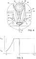
- a typical trend of the power supplied by the electric generator of the wind turbine as a function of the wind speed is depicted in the graph in figure 5 , in which the wind speed may be exploited in a speed range between a minimum exploitable wind speed value V1 and a maximum exploitable wind speed value V2.
- wind speeds exceed V2, electric energy may not be generated due to physical and structural limitations both of the wind turbine and of the devices for generating electric energy.
- the power supplied increases with the wind speed from a minimum power value P min to a maximum power value P max .
- the power supplied remains constant at a value P max due to physical limitations of the devices for generating electric energy and to structural limitations.
- the rotor When the wind exceeds the maximum exploitable wind speed value V2, and therefore takes on a speed value ranging between V2 and a maximum wind speed value V max , the rotor is substantially stopped, thus limiting the angular rotation in order to limit the aerodynamic loads exerted by the wind on the wind turbine.
- the wind turbine is therefore stopped between the maximum exploitable wind speed value V2 and the maximum wind speed V max , in order to resist a storm and not generate electric energy.
- the mechanical stresses exerted by the wind on the turbine under such conditions are extremely high.
- folding blade wind turbines have been designed in order to fold such blades in a standby mode when the wind is greater than V2.
- Patent Application US 2010/0133848 discloses a horizontal axis wind turbine comprising a beam hub and two blades hinged to the two opposite ends of the beam hub at hinge points spaced apart from each other in order to fold such blades towards the tower.
- the two blades are therefore restrained to be folded about two distinct and separate folding axes.
- Such a wind turbine is not capable of resisting high wind speed values; or, in order to resist, it should comprise an extremely rigid and resistant, and accordingly expensive, structure.
- Patent Application US 2007/0243063 discloses a folding blade wind turbine which proposes to minimize damage during storms or other events with strong winds and to facilitate maintenance.
- This wind turbine comprises three blades, two of which foldable about separate hinge points arranged at the free ends of respective blade bases fastened radially to the rotor.
- this wind turbine also hinders the encumbrance, or the resistant surface, from being reduced when the blades are closed, to such a degree as to resist high values or peaks in wind speed, because such blades remain spaced apart from the tower at least at the hinge points of the blade bases.
- the wind turbine should also ensure correct and safe maintenance of the blades in the folded position, while opposing the minimum aerodynamic resistance also in such a folded position.
- none of the known solutions allows the blades to be closed in such a way as to substantially reduce the aerodynamic resistance during such a closing step, in a quick and accurate manner.
- none of the known solutions allows the blades to be positioned in a folded position capable of ensuring the minimum aerodynamic resistance in the folded position and the correct maintenance of such a position despite the criticality of the environmental conditions.
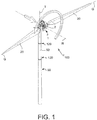
- a folding blade wind turbine is generally indicated with numeral 100.
- a method folding wind blades according to the invention is generally indicated with numeral 30, and a method for unfolding wind blades according to the invention is generally indicated with numeral 40.
- the wind turbine 100 comprises a rotor unit 1 comprising a rotor body 2 arranged to rotate about a rotor axis R and a tower 50 adapted to support said rotor unit of wind turbine 1.
- Tower 50 defines a tower axis T arranged along a main direction of extension of tower 50.
- the tower defines an outer lateral surface 53 of tower of wind turbine.
- the wind turbine 100 comprises two blades 20, each defining a respective blade longitudinal axis G arranged along a main direction of blade extension, and an outer surface 80 of blade, which externally delimits said blade 20.
- the blades 20 are connected to the rotor unit 1 to rotate with respect to each other between an unfolded position and a folded position and vice versa.
- both blades 20 are arranged with the respective blade longitudinal axis G along a same unfolded blade axial plane W-W comprising the rotor axis R, on opposite sides with respect to the rotor axis (R).
- tower 50 defines a tower axis T along a main direction of extension of tower 50, in which, in said stopped angular position, the two blades 20 are arranged so that the unfolded blade axial plane W-W is substantially orthogonal to the tower axis T.
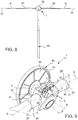
- the blades 20 are arranged, or orientated, to be able to be affected by the wind to bring said rotor body 2 into rotation about said rotor axis R, while, in the folded position, the two blades 20 are angularly close to each other and placed side-by-side with the tower 50.
- Blade longitudinal axis G means an axis along which the larger dimension of blade 20 itself is arranged.
- the blade longitudinal axis G is a main axis of extension of blade 20.
- the blade longitudinal axis G is, for example, a substantially rectilinear axis.
- the blade longitudinal axis G is tilted with respect to a radial plane Q which is orthogonal to the rotor axis R, according to a preset angle d.
- the wind turbine comprises at least one actuator 5 arranged to rotate the two blades 20 with each other between the unfolded position and the folded position and vice versa.
- the rotor unit 1 further comprises at least one actuator 5 as described above, which is arranged to move the two blade folding structures 4 with respect to each other.
- said at least one actuator 5 comprises at least one linear actuator, for example at least one hydraulic cylinder, or at least one pneumatic cylinder, or at least one actuator with a screw-nut system, for example at least one screw system with recirculating balls.
- said at least one actuator 5 comprises at least one rotating actuator, for example at least one gear-motor, comprising a rotary motor and a reduction gear.
- the rotary motor is an electric motor or a hydraulic motor.
- the wind turbine may comprise a folding brake 19 separated by the at least one actuator 5.
- the rotor unit 1 comprises a folding brake 19, for example associated with actuator 5, the folding brake 19 being adapted to oppose the movement of the blades 20 between the unfolded position and the folded position.
- the folding brake 19 is a mechanical brake, for example a disc brake or a drum brake.
- the folding brake 19 is integrated together with actuator 5.
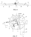
- the two blade folding structures 4 are pivotally restrained to each other about a same hinge axis P. Thereby, the folding structures 4 are adapted to rotate the at least two blades 20 about the hinge axis P between the unfolded position and the folded position and vice versa.
- the two blade folding structures 4 are pivotally engaged with the rotor body 2 about a hinge axis P.
- the blade folding structures 4 are pivotally engaged about different hinge axes P.
- Each of said two blade folding structures 4 supports only one blade 20.
- the wind turbine occupies an extremely reduced volume in all directions of the wind when the blades 20 are in the folded position. Due to the presence of only one hinge axis P, the blades 20 in the folded position are very close to each other and they may embrace tower 50 laterally.
- such a wind turbine since such a wind turbine has a very small encumbrance in the direction transverse to the wind when the blades 20 are in the folded position, such a wind turbine opposes a reduced aerodynamic resistance, i.e. the resultant of the forces applied by the wind to the structure of the wind turbine, according to the present invention, is less than the one applied to known wind turbines, a less sturdy structure with respect to known turbines is required, the wind speed being equal.
- the hinge axis P is tilted with respect to the rotor axis R according to a preset tilt angle b.
- the tilt angle b ranges between 1° and 40°, preferably ranges between 5° and 20°, and still more preferably between 8° and 12°.
- the tilt angle b is selected so that, when the blade folding structures 4, or the blades 20, are in the folded position, the blades 20 are placed side-by-side with the tower 50 in a tilted manner with respect to the tower axis T, according to a preset closure angle with respect to the rotor axis R.
- the rotor unit 1 comprises two blade folding structures 4 connected to the rotor body 2 and each comprising a blade fastening portion 17 for fastening an end portion of a respective blade 20 of each of said two blade folding structures 4.
- the rotor unit 1 for each blade folding structure 4, the rotor unit 1 comprises a blade joint 15 adapted to fasten a blade fastening end 20' to a respective one of said at least two blade folding structures 4, so as to allow the only rotation of blade 20 about the blade longitudinal axis G with respect to the blade folding structure 4.
- the blade joint 15 is adapted to carry a respective blade 20, thus preventing any movement of blade 20 with respect to the folding structure 4, other than the rotation of blade 20 about its own blade longitudinal axis G with respect to the blade folding structure 4.
- the blade joint 15 comprises a blade orientation actuator 21 for actuating the rotation of blade 20 about the blade longitudinal axis G.
- the rotation of blade 20 about its own blade longitudinal axis G allows the helix pitch of the wind turbine to be varied.
- the blocking/unblocking devices 25 comprise a rotatable hook element 25' mounted on one of the blade folding structure 4 and the rotor body 2, and a coupling element 25" which is integral with the other of the blade folding structure 4 and the rotor body 2, the hook element 25' being adapted to be removably engaged with the coupling element 25".
- the blocking/unblocking devices 25 comprise an actuator adapted to actuate said blocking/unblocking devices, for example a motorized actuator, for example an automatic motorized actuator.
- the electric generator 60 is of the "direct drive” type.
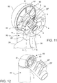
- it comprises an outer annular stator 61 and an inner disc rotor 62, which is adapted to rotate coaxially and internally to the outer annular stator 61.
- the inner disc rotor 62 is, for example, spliced onto the rotor body 2 so as to allow the rotation of the rotor body 2 about the rotor axis R.
- This type of electric generator 60 allows the encumbrance of the generator itself 60 to be reduced in the direction which extends along the rotor axis R, or along an axial direction of electric generator 60. This allows the distance of the center of gravity of the rotor unit 1 to be reduced with respect to the turbine orientation axis S, and therefore the overhang of the rotor unit 1 to be reduced with respect to tower 50.
- This aspect is particularly significant in order to give the wind turbine high structural strength, considering the great size and weight of the rotor unit 2. This aspect is highly advantageous also because it allows the overall size, and therefore the aerodynamic resistance of the rotor body 2, to be reduced.
- the outer annular stator 61 is fastened to a supporting portion 51, which is connected to the upper end of tower 50 in a rotatable manner about the turbine orientation axis S.
- the wind turbine 100 comprises a rotor brake 90 adapted to oppose the rotation of the rotor unit 1 about the rotor axis R.
- Such a rotor brake 90 is adapted to oppose the rotation of the rotor body 2 about the rotor axis R.
- the rotor brake 90 is a mechanical brake or an electromagnetic brake.
- the rotor brake 90 has a first portion which is integral with the rotor body 2, and a second portion which is stationary with respect to the rotor body 2, for example the second portion is integral with the outer annular stator 61 of the electric generator 60.
- such a brake is a disc brake, in which for example, the disc brake has a brake disc 92 keyed onto the rotor body 2 and pincer bodies 91 mounted on the outer annular stator 61 of the electric generator 60, which are adapted to force pads against the brake disc 92 to brake the rotation of the rotor body 2.
- the rotor unit 1, blades 20, electric generator 60 assembly is contained inside a containment shell 52, or nacelle.
- the shape of the containment shell 52 is designed so as to further reduce the aerodynamic resistance against the action of the wind.
- the wind turbine 100 comprises blade fastening devices 120 which can be actuated between a fastened position, in which the blades 20 are restrained to tower 50 in the folded position, and an unfastened position, in which the blades 20 are free to move away from tower 50.
- the blade fastening devices 120 comprise a hook element 121 associated with one of blade 20 and tower 50, and a coupling seat 122 associated with the other of blade 20 and tower 50, said hook element 121 being operable between an engaged position with the coupling seat 122 and a disengaged position from the coupling seat 122.
- the hook elements 121 comprise actuators for the actuation between the engaged position and the disengaged position.
- the wind turbine further comprises a supply unit 300, which in the absence of an external power supply to the wind turbine supplied by the electric network, serves to allow the blades 20 to be folded and the safety measures thereof to be implemented.
- the supply unit 300 is adapted to supply at least one of the following devices or a combination thereof:
- the wind turbine according to the invention further comprises a blade unfolding/folding control unit 200 having an input for receiving an unfold/fold command signal, and is operatively connected with at least one of the following devices, or a combination thereof:
- the blade unfolding/folding control unit 200 is programmed to execute the method for folding wind blades 30 and the method for unfolding wind blades 40 described below.
- the blade unfolding/folding control unit 200 is operatively connected with actuator 5 to allow an accurate approach of the blade 20 to tower 50 when the blades 20 are in the folded position and to actuate the blades 20 from the folded position to the unfolded position.
- the blade unfolding/folding control unit 200 is operatively connected with said folding brake 19 to control the rotation speed of the blade folding structures 4 between the unfolded position and the folded position and vice versa.
- the blade unfolding/folding control unit 200 is operatively connected to at least one blade orientation actuator 21 to command the blade pitch.
- the blade unfolding/folding control unit 200 is operatively connected to said blocking/unblocking devices 25 to command the blocking of the blade folding structures 4 when they are in the unfolded position and to release the blade folding structures 4 to allow the rotation thereof from the unfolded position to the folded position.
- the blade unfolding/folding control unit 200 is operatively connected to at least one pincer body 91 to oppose the rotation of the rotor body 2 about the rotor axis R.
- the blade unfolding/folding control unit 200 is operatively connected to the blade fastening devices 120 to block the blades 20 in the position close to tower 50 when they are in the folded position.
- the blade unfolding/folding control unit 200 is operatively connected to a supply unit 300 for ordering the supply of the devices adapted to allow the folding to be executed in the absence of supply from the electric network.
- the blade unfolding/folding control unit 200 comprises a central processing unit (CPU) and a memory, for example a programmable memory, for executing a preset sequence of steps for actuating the wind turbine 100 to rotate the blades 20 between the unfolded position and the folded position and vice versa.
- CPU central processing unit
- memory for example a programmable memory
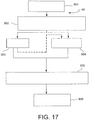
- the aforesaid objects and advantages are obtained by means of the method for folding 30 wind blades, an example of which is shown in figure 16 .
- Such a method comprises a step of stopping 404 the rotation of the rotor body 2 in a preset stopped angular position, in which said blades 20 are arranged in the unfolded position.
- the stopped angular position has the blades 20 substantially horizontal and therefore orthogonal to tower 50.
- Such a stopping step 404 serves to stop the rotor body 2 so as to allow the blades 20 to be folded from such a position.
- the step of stopping 404 the rotation of the rotor body 2 in a preset stopped angular position is preceded by a step of reducing 403 the rotation speed of the rotor unit 1 up to zeroing the speed at the preset stopped angular position.
- the step of reducing 403 the rotation speed of the rotor unit 1 comprises a commanded braking step 401, which is preferably controlled, of the rotation of the rotor body 2.
- such a commanded braking step 401 may be executed by means of the aforesaid rotor brake 90 by actuating the pincer bodies 91. Thereby, a mechanical braking of the rotor body 2 is obtained.
- the step of reducing 403 the rotation speed of the rotor unit 1 is executed by actuating each blade orientation actuator 21 so as to orientate the blades 20 about the respective blade longitudinal axis G according to an angle of incidence such to cause a highly aerodynamic resistance on the blades 20 during the rotation thereof about the rotor axis R.
- the step of reducing 403 the rotation speed of the rotor unit 1 is executed by means of a simultaneous action of mechanical braking and aerodynamic braking.
- the folding method comprises a step of maintaining 405 the preset stopped angular position, for example said maintenance step occurs by means of the constant actuation of the pincer bodies 91.
- the folding method 30 comprises a step of unblocking 406 the blade folding structures 4 by the actuation of the blocking/unblocking devices 25.
- the folding method 30 further comprises a first step 407 of rotating the blades 20 from the stopped angular position to the folded position, about the rotation axis P in which the two blades 20 are arranged substantially along said tower 50.
- the folding method 30 further comprises a step of braking 408 the blades 20 in opposition to the rotation of the blades from the stopped angular position to the folded position. Thereby, the descent speed of the blades may be adjusted.
- the braking step 408 is executed by actuating said at least one actuator 5 as a brake.
- the at least one actuator 5 is used in opposition to the action of the force of gravity of the blades 20, in order to slow down the downward travel thereof, or the travel thereof towards tower 50.
- the rotor unit 1 comprises a folding brake 19 adapted to oppose the movement of the blades 20 between the unfolded position and the folded position, wherein the step of rotating the blades 20 from the stopped angular position to the folded position is executed in cooperation with a step of actuating said folding brake 19.
- the braking step 408 is executed by actuating a folding brake 19.
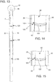
- the folding method 30 further comprises a step of first orientation 409 of the blades 20 about the blade longitudinal axis G so that the outer surface 80 of blade is arranged at least partly tangent to said outer lateral surface 53 of tower.
- a step of first orientation 409 occurs by actuating the blade orientation actuator 21 of each blade joint 15.
- the step of first rotation 407 of the blades 20 from the stopped angular position to the folded position is executed in cooperation with a braking step 408 in opposition to the rotation of the blades 20 and in cooperation with the first orientation step of the blades 20.
- the braking 408 of the blades and the orientation 409 of the blades 20 about the longitudinal axis G thereof occurs in the shadow of the falling movement of the blades 20, or of first rotation 407 of the blades 20 up to the folded position, thus reducing the overall time required to fold and position the blades 20.
- This reduction of time is very important for the purposes of the mechanical resistance of the structure under the adverse environmental conditions in which it should occur.
- the step of first rotation 407 of the blades 20 from the stopped angular position to the folded position occurs due to the effect of the applied force of gravity of the blades 20.
- the force of gravity of the blades 20 is exploited to facilitate the downward rotation thereof, that is towards tower 50, which is generally substantially vertical.
- the method for folding 30 further comprises a step of releasing 410 the folding brake 19 to allow successive steps of accurate actuation of the orientation and rotation of the blades 20.
- the folding method 30 comprises a second step of orientating 411 the blades 20 about the blade longitudinal axis G thereof in order to accurately adjust the position of the blades 20 when the blades 20 are in the folded position, said second orientation step 411 being executed by actuating said blade orientation actuator 21 of each blade 20.
- This second orientation rotation 411 allows the blades 20 to close about tower 50 by embracing it and exploiting the curvature of the outer surfaces 80 of blade to reduce the space interposed between the outer surfaces 80 of blade and the outer lateral surface 53 of tower.
- the blade folding method 30 comprises a step of further moving the blades 20 close to tower 50 by means of a second step of rotating the blade folding structures 4.
- the step of further moving the blades 20 closer may be executed by actuating the actuators 5 to carry out an accurate approach to tower 50.
- the step of second rotation 412 of the blades 20 is executed in cooperation with a second orientation 411.
- the second orientation 411 of the blades 20 occurs in the shadow of the second rotation movement, thus reducing the overall time required to fold and position the blades 20.
- the step of further moving closer is maintained up to securing the blades 20 to tower 50.
- blades 20 when the blades 20 are in the folded position, they form, together with tower 50, a profile with reduced aerodynamic resistance.
- the step of mechanical braking 401 and aerodynamic braking 402 of the blades 20, the step of stopping 404 the rotation of the rotor body 2, the step of maintaining the stopped angular position 405, the step of unblocking 406 the blade folding structure 4, the step of first rotation 407 of the blades 20, the braking step 408, the step of first orientation 409 of the two blades 20, the step of releasing 410 the folding brake, the step of second orientation 411 of the blades 20 and the step of second orientation 412 of the blades 20 are controlled by means of the blade unfolding/folding control unit 200.
- control unit carries out such steps by actuating the rotor brake 90 through the pincer bodies 91, the blade orientation actuators 21, the blocking/unblocking devices 25, the at least one actuator 5, the at least one folding brake 19, in a synchronized manner. If an electric network supply is not present, the supply of said devices occurs by means of a power supply unit 300.
- the blade folding method 30 comprises a step of fastening 413 the blades 20 to tower 50 when said blades 20 are in the folded position by actuating said blade fastening devices 120.
- the blade folding method 30 comprises a step of interrupting 414 the actuation of the at least one actuator 5, after the step of fastening 413 the blades 20 to tower 50.
- the blades 20 are left free in the relative deformation between blades 20 and tower 50 due to strong winds, thus avoiding excessive and irregular structural loads.
- the step of fastening 413 the blades 20 to tower 50 and the step of interrupting 414 the actuation of actuator 5 may be controlled by means of the blade unfolding/folding control unit 200.
- the control unit 200 carries out such steps by actuating the blade fastening device 120 and interrupting the actuation of actuator 5. If the electric network supply is not present, the supply of said devices occurs by means of a supply unit 300.
- a blade folding command 30 may be provided to the wind turbine automatically, or manually, when the speed of the wind which hits the wind turbine reaches the maximum exploitable wind speed value V2, or following a weather forecast, or following the need for maintenance or inspection.
- the aforesaid blade folding method 30 allows to avoid damages to the wind turbine, the wind turbine comprising blades 20 having large size and large surfaces resisting to the wind and to high weights.
- the aforesaid objects and advantages are obtained by means of a method 40 unfolding wind blades for a wind turbine 100 having foldable blades 20, as described in the present description.
- the method 40 for unfolding wind blades includes a step of stopping 501 the rotor body 2 in the position of folded blades 20.
- Such a stopping step 501 serves to prevent any rotation movement by the rotor body 2 so as to allow the unfolding of the blades 20 from such a position.
- the step of rotating the two blades 20 from the folded position to the unfolded position is preceded by a step of unfastening 502 said blade fastening devices 120, thus freeing the blades 20 from tower 50.
- the method for unfolding wind blades 40 comprises a rotation step 503 of the blades 20 from the folded position to the unfolded position, about the hinge axis P, by actuating said at least one actuator 5.
- the blade longitudinal axis G and the rotor axis R lie on a same unfolded blade axial plane W-W.
- the unfolded blade axial plane W-W is substantially orthogonal to the tower axis T.
- the method for unfolding wind blades 40 further comprises the step of blocking 505 the blade folding structures 4 by the actuation of the blocking/unblocking devices 25.
- the blade method for unfolding 40 comprises a step of allowing the rotor body 2 to rotate 506, for example by opening the pincer bodies 91 of the brake disc 90.
- the ⁇ method 20 for unfolding the wind blades further comprises a step of orientating 504 the blades 20 so that the blades are arranged according to an angular position about the blade longitudinal axis G such as to allow the wind to bring the blades 20 into rotation about the rotor axis R, by actuating said blade orientation actuator 21.
- the step of rotating 503 the blades 20 from the folded position to the unfolded position is executed simultaneously with said step of orientating 504 the two blades 20.
- the step of stopping 501 the rotation of the rotor body 2, the step of unfastening 502 the blade fastening devices 120 from tower 50, the step of rotating 503 the blades 20, the step of orientating the blades 20, the step of blocking 505 the blade folding structures 4 and the step of allowing the rotor body 2 to rotate 506 are preferably controlled by means of the blade unfolding/folding control unit 200.
- control unit carries out such steps by actuating the pincer bodies 91, the blade fastening devices 120, the at least one actuator 5, the blocking/unblocking devices 25 and the blade orientation actuators 21, in a synchronized manner.
Landscapes
- Engineering & Computer Science (AREA)
- Life Sciences & Earth Sciences (AREA)
- Sustainable Development (AREA)
- Sustainable Energy (AREA)
- Chemical & Material Sciences (AREA)
- Combustion & Propulsion (AREA)
- Mechanical Engineering (AREA)
- General Engineering & Computer Science (AREA)
- Wind Motors (AREA)
Claims (15)
- Procédé (30) pour replier des pales éoliennes d'une turbine éolienne (100) ayant des pales repliables (20), la turbine éolienne (100) comprenant :- une unité de rotor (1) comprenant un corps de rotor (2) agencé pour tourner autour d'un axe de rotation (R),- une tour (50) adaptée pour porter l'unité de rotor (1), la tour définissant une surface latérale extérieure (53) de la tour,- deux pales (20), chacune définissant un axe longitudinal de pale (G) respectif agencé le long d'une direction principale de l'étendue de la pale et une surface extérieure de pale (80), les pales (20) étant attachées au corps de rotor (2) de façon à tourner l'une par rapport à l'autre autour d'un axe charnière (P) entre une position angulaire arrêtée ouverte et une position repliée, où, dans la position angulaire arrêtée ouverte, les deux pales (20) sont disposées, avec l'axe de pale (G) respectif le long d'un même plan axial de pale ouverte (W-W) comprenant l'axe de rotor (R), dans des positions qui sont opposées l'une à l'autre par rapport à l'axe de rotor (R), afin d'être en mesure d'être affectée par le vent pour mettre le corps de rotor (2) en rotation autour de l'axe de rotor (R), et où, dans la position repliée, lesdites au moins deux pales (20) sont angulairement proches l'une de l'autre et placées côte à côte avec la tour (50),- au moins un actionneur (5) agencé pour faire tourner les deux pales (20) l'une par rapport à l'autre entre la position angulaire arrêtée ouverte et la position repliée,- pour chacune des deux pales (20), une articulation de pale (15) interposée entre le corps de rotor (2) et une extrémité de fixation de pale (20'), comprenant un actionneur d'orientation de pale (21) adapté pour actionner la rotation de la pale (20) autour de l'axe longitudinal de pale (G),- une unité de commande d'ouverture/repliage (200) ayant une entrée pour recevoir un signal de commande d'ouverture/repliage, l'unité de commande étant fonctionnellement connectée audit au moins un actionneur (5) et l'actionneur d'orientation de pale (21),le procédé (30) pour replier des pales éoliennes étant caractérisé en ce qu'il comprend les étapes de :- arrêter (404) la rotation du corps de rotor (2) dans une position angulaire arrêtée prédéterminée, les pales (20) étant dans la position ouverte,- faire tourner (407) les deux pales (20) l'une par rapport à l'autre, autour de l'axe charnière (P), de la position angulaire arrêtée à la position repliée, où les deux pales (20) sont disposées sensiblement le long de la tour (50),- orienter (409), en actionnant l'actionneur d'orientation de pale (21), les deux pales (20) de façon que la surface extérieure de pale (80) soit disposée au moins partiellement de manière tangentielle à la surface latérale extérieure (53) de la tour,- l'étape d'arrêter (404) la rotation du corps de rotor, l'étape de faire tourner (407) les deux pales (20), l'étape de faire orienter (409) les deux pales (20) étant commandées à l'aide de l'unité de commande d'ouverture/repliage (200).
- Procédé selon la revendication 1, caractérisé en ce que l'étape de faire tourner (407) les deux pales (20) de la position angulaire arrêtée à la position repliée est mise en œuvre en même temps que l'étape d'orientation (409) des deux pales (20).
- Procédé selon au moins une revendication précédente, caractérisé en ce que l'étape de faire tourner (407) les deux pales (20) de la position angulaire arrêtée à la position repliée se produit dû au résultat de la force de gravité appliquée des deux pales (20), et/ou en ce que l'étape de faire tourner (407) les pales (20) de la position angulaire arrêtée à la position repliée se produit en coopération avec une étape de freinage (408) à l'encontre de la rotation des pales (20) de la position angulaire arrêtée à la position repliée,
l'étape de freinage (408) étant mise en œuvre en actionnant ledit au moins un actionneur (5) comme frein, ou
l'étape de freinage (408) étant mise en œuvre en actionnant un frein de repliage (19), le frein de repliage (19) étant inclus dans l'unité de rotor (1). - Procédé selon au moins une revendication précédente, caractérisé en ce que l'étape d'arrêter (404) la rotation du corps de rotor (2) dans une position angulaire arrêtée prédéterminée est précédée d'une étape pour faire réduire (403) la vitesse de rotation de l'unité de rotor (1) jusqu'à atteindre le niveau zéro à la position angulaire arrêtée prédéterminée, l'étape pour faire réduire (403) la vitesse de rotation de l'unité de rotor (1) étant mise en œuvre en actionnant chaque actionneur d'orientation de pale (21) pour orienter les pales (20) autour de l'axe longitudinal de pale (G) respectif selon un angle d'incidence afin de provoquer sur les pales, à l'aide d'une étape de freinage aérodynamique (402), une haute résistance (20) aérodynamique à la rotation de celles-ci autour de l'axe de rotor (R).
- Procédé selon au moins une revendication précédente, caractérisé en ce que la turbine éolienne (100) comprend des dispositifs (25) de blocage/déblocage pour le blocage des pales (20) par rapport au corps de rotor (2) lorsqu'elles sont en position ouverte, et pour le relâchement des pales (20) par rapport au corps de rotor (2) lorsque la rotation des pales (20) de la position ouverte à la position repliée est requise, caractérisé en ce que l'étape de faire tourner (407) les deux pales (20) de la position angulaire arrêtée à la position repliée est précédée d'une étape de déblocage (406) desdits dispositifs de blocage/déblocage (25).
- Procédé selon au moins une revendication précédente, comprenant une deuxième étape (411) d'orientation des deux pales (20) autour de l'axe longitudinal de pale (G) de celles-ci pour ajuster exactement la position des pales (20) lorsque les pales (20) sont en position repliée, la deuxième étape d'orientation (411) étant mise en œuvre en actionnant l'actionneur d'orientation de pale (21) de chaque pale (20).
- Procédé selon au moins une revendication précédente, comprenant une deuxième étape (412) de faire tourner les deux pales (20) autour de l'axe charnière (P) pour ajuster exactement la position des pales (20) lorsque les pales (20) sont en position repliée, la deuxième étape de faire tourner (412) étant mise en œuvre en actionnant l'actionneur (5).
- Procédé selon au moins une revendication précédente, caractérisé en ce que la deuxième étape de faire orienter (411) les pales (20) est mise en œuvre en coopération avec la deuxième étape de faire tourner (412) les pales (20).
- Procédé selon au moins une revendication précédente, caractérisé en ce que, lorsque les deux pales (20) sont en position repliée, chaque pale (20) et la tour (50) forment ensemble une configuration avec une résistance aérodynamique réduite.
- Procédé selon au moins une revendication précédente, caractérisé en ce que la turbine éolienne (100) comprend des moyens de fixation de pale (120) pouvant être actionnés entre une position fixée, dans laquelle les pales (20) sont restreints à la tour (50) dans la position repliée, et une position libre, dans laquelle les pales sont libres de s'écarter de la tour (50), le procédé comprenant en outre une étape de fixation (413) des pales (20) à la tour (50), lorsque les pales (20) sont en position repliée, par actionnement des moyens de fixation de pale (120).
- Procédé (40) pour ouvrir des pales éoliennes d'une turbine éolienne (100) ayant des pales repliables (20), la turbine éolienne (100) comprenant :- une unité de rotor (1) comprenant un corps de rotor (2) agencé pour tourner autour d'un axe de rotation (R),- une tour (50) adaptée pour porter l'unité de rotor (1), la tour définissant une surface latérale extérieure (53) de la tour,- deux pales (20), chacune définissant un axe longitudinal de pale (G) respectif agencé le long d'une direction principale de l'étendue de la pale et une surface extérieure de pale (80), les pales étant attachées au corps de rotor (2) de façon à tourner l'une par rapport à l'autre autour d'un axe charnière (P) entre une position angulaire arrêtée ouverte et une position repliée, où, dans la position angulaire arrêtée ouverte, les deux pales (20) sont disposées avec l'axe de pale (G) respectif le long d'un même plan axial de pale ouverte (W-W) comprenant l'axe de rotor (R) dans des positions qui sont opposées l'une à l'autre par rapport à l'axe de rotor (R), afin d'être en mesure d'être affectée par le vent pour mettre le corps de rotor (2) en rotation autour de l'axe de rotor (R), et où, dans la position repliée, lesdites au moins deux pales (20) sont angulairement proches l'une de l'autre et placées côte à côte avec la tour (50),- au moins un actionneur (5) agencé pour faire tourner les deux pales (20) l'une par rapport à l'autre entre la position angulaire arrêtée ouverte et la position repliée,- pour chacune des deux pales (20), une articulation de pale (15) interposée entre le corps de rotor (2) et une extrémité de fixation de pale (20'), comprenant un actionneur d'orientation de pale (21) adapté pour actionner la rotation de la pale (20) autour de l'axe longitudinal de pale (G),- une unité de commande d'ouverture/repliage (200) ayant une entrée pour recevoir un signal de commande d'ouverture/repliage, l'unité de commande étant fonctionnellement connectée audit au moins un actionneur (5) et l'actionneur d'orientation de pale (21),le procédé (40) pour ouvrir des pales éoliennes étant caractérisé en ce qu'il comprend les étapes de :- faire tourner (503) les deux pales (20) l'une par rapport à l'autre, en actionnant ledit au moins un actionneur (5), de la position repliée, dans laquelle les deux pales (20) sont disposées sensiblement le long de la tour (50) et sont orientées de façon que la surface extérieure de pale (80) soit disposée au moins partiellement de manière tangentielle à la surface latérale extérieure (53) de la tour, à la position ouverte,- orienter (504), en actionnant l'actionneur d'orientation de pale (21), les deux pales (20) de façon que la surface extérieure de pale (80) soit disposée dans une position angulaire autour de l'axe longitudinal de pale (G) telle que le vent puisse mettre les pales (20) en rotation autour de l'axe de rotor (R),- rendre possible que le corps de rotor (2) puisse tourner (506) autour de l'axe de rotor (R),- l'étape de faire tourner (503) les pales (20), l'étape d'orienter (504) et l'étape de rendre possible que le corps de rotor (2) puisse tourner (506) étant commandées à l'aide de l'unité de commande de ouverture/repliage (200).
- Procédé selon la revendication 11, caractérisé en ce que l'étape pour faire tourner (503) les deux pales (20) de la position repliée à la position ouverte est suivie d'une étape de blocage (505) des pales (20) dans la position ouverte par rapport au corps de rotor à l'aide de dispositifs (25) de blocage/déblocage compris dans la turbine éolienne (100) qui sont adaptés pour bloquer les pales (20) par rapport au corps de rotor (2) lorsqu'ils sont en position ouverte et qui sont adaptés pour libérer les pales (20) par rapport au corps de rotor (2) lorsque la rotation des pales (20) de la position ouverte à la position repliée est requise.
- Procédé selon au moins une des revendications 11 à 12, caractérisé en ce que la dite étape pour faire tourner (503) les pales (20) d'une position repliée à une position ouverte est précédée d'une étape de détachement (502) des pales (20) de la tour (50) par un actionnement des moyens de fixation de pale (120), les moyens de fixation de pale (120) étant compris dans la turbine éolienne et étant opérationnels entre une position fixée, dans laquelle les pales (20) sont restreints à la tour (50) dans la position repliée, et une position libre, dans laquelle les pales (20) sont libres de s'écarter de la tour (50).
- Procédé selon au moins une des revendications 11 à 13, caractérisé en ce que l'étape de détachement (502) des pales (20) de la tour est précédé d'une étape d'arrêt (501) du corps de rotor (2).
- Procédé (35) pour actionner des pales d'une turbine éolienne (100) ayant des pales repliables, comprenant :- le procédé (30) pour replier des pales éoliennes selon au moins une des revendications 1 à 10,- le procédé (40) pour ouvrir des pales éoliennes selon au moins une des revendications 11 à 14.
Applications Claiming Priority (1)
| Application Number | Priority Date | Filing Date | Title |
|---|---|---|---|
| PCT/IT2016/000104 WO2017187459A1 (fr) | 2016-04-28 | 2016-04-28 | Procédé pour plier des pales éoliennes et procédé pour ouvrir des pales éoliennes pour une turbine éolienne ayant des pales pliables |
Publications (2)
| Publication Number | Publication Date |
|---|---|
| EP3449121A1 EP3449121A1 (fr) | 2019-03-06 |
| EP3449121B1 true EP3449121B1 (fr) | 2020-04-22 |
Family
ID=56369141
Family Applications (1)
| Application Number | Title | Priority Date | Filing Date |
|---|---|---|---|
| EP16736254.0A Active EP3449121B1 (fr) | 2016-04-28 | 2016-04-28 | Procédé pour plier des pales éoliennes et procédé pour ouvrir des pales éoliennes pour une turbine éolienne ayant des pales pliables |
Country Status (2)
| Country | Link |
|---|---|
| EP (1) | EP3449121B1 (fr) |
| WO (1) | WO2017187459A1 (fr) |
Families Citing this family (4)
| Publication number | Priority date | Publication date | Assignee | Title |
|---|---|---|---|---|
| CN109162868A (zh) * | 2018-10-17 | 2019-01-08 | 合肥凌山新能源科技有限公司 | 一种小型风力发电装置用扇叶收敛器 |
| CN109653941A (zh) * | 2018-12-27 | 2019-04-19 | 广东华蕴新能源有限公司 | 一种叶片聚拢式抗大风风力发电机组及其控制方法 |
| CN110173396A (zh) * | 2019-06-28 | 2019-08-27 | 内蒙古工业大学 | 一种伞形风力机用电气伺服控制系统 |
| CN112283023B (zh) * | 2020-11-18 | 2024-07-16 | 西安热工研究院有限公司 | 一种叶片位置可变的双叶片风轮及其工作方法 |
Family Cites Families (4)
| Publication number | Priority date | Publication date | Assignee | Title |
|---|---|---|---|---|
| DE4413278A1 (de) * | 1994-04-16 | 1995-10-19 | Konrad Prof Dipl Ing Dr I Zuse | Windkraftanlage mit einem Mast, der nach Maßgabe der Windgeschwindigkeit auf unterschiedliche Masthöhe ein- und ausfahrbar ist |
| DK176552B1 (da) * | 2005-12-29 | 2008-08-04 | Lm Glasfiber As | Variabelt speed nav |
| US20070243063A1 (en) * | 2006-03-17 | 2007-10-18 | Schellstede Herman J | Offshore wind turbine structures and methods therefor |
| US7821148B2 (en) * | 2009-08-14 | 2010-10-26 | Piasecki Frederick W | Wind turbine |
-
2016
- 2016-04-28 WO PCT/IT2016/000104 patent/WO2017187459A1/fr not_active Ceased
- 2016-04-28 EP EP16736254.0A patent/EP3449121B1/fr active Active
Non-Patent Citations (1)
| Title |
|---|
| None * |
Also Published As
| Publication number | Publication date |
|---|---|
| WO2017187459A1 (fr) | 2017-11-02 |
| EP3449121A1 (fr) | 2019-03-06 |
Similar Documents
| Publication | Publication Date | Title |
|---|---|---|
| EP2126350B2 (fr) | Eolienne et procédé pour créer au moins une ouverture dans le nez de rotor sur le moyeu d'un rotor d'éolienne | |
| EP3449121B1 (fr) | Procédé pour plier des pales éoliennes et procédé pour ouvrir des pales éoliennes pour une turbine éolienne ayant des pales pliables | |
| JP4100520B1 (ja) | アップウインド型風車及びその退避運転方法 | |
| EP3036434B1 (fr) | Éolienne pour faibles vitesses de vent | |
| US20150086367A1 (en) | Portable crane for use in wind turbines | |
| US9447776B2 (en) | Turning device to rotate the rotatable part of a wind turbine | |
| EP3029317B1 (fr) | Procédé et appareil pour la réduction de la fatigue et de charges de rafales sur des pales d'éolienne | |
| US11686290B2 (en) | Lifting device for a wind turbine rotor blade | |
| CN101490410A (zh) | 可伸缩转子叶片结构 | |
| EP3808970B1 (fr) | Installation de pales d'éolienne sur des moyeux | |
| JP4568735B2 (ja) | アップウィンド型風車の運転装置及びその運転方法 | |
| JP2014181711A (ja) | 負荷補償デバイスのためのフェールセーフデバイス | |
| EP3449120B1 (fr) | Unité de rotor d'une turbine éolienne ayant des pales de vent pliables et turbine éolienne comprenant une unité de rotor | |
| US11466663B2 (en) | Wind turbine with a pivoted rotor blades, wire and release mechanism for stopping | |
| CN101498280B (zh) | 用于停止风力涡轮机的方法 | |
| KR200440431Y1 (ko) | 풍력 발전기 | |
| CN113120776A (zh) | 配备有可调节风荷载系统的俯仰悬臂塔式起重机 | |
| EP4058670B1 (fr) | Éolienne à pâles articulées dotée d'un axe incliné et/ou d'un rotor conique | |
| JPH0343468B2 (fr) | ||
| JP5248285B2 (ja) | 風力発電用のプロペラ型タービン装置 |
Legal Events
| Date | Code | Title | Description |
|---|---|---|---|
| STAA | Information on the status of an ep patent application or granted ep patent |
Free format text: STATUS: THE INTERNATIONAL PUBLICATION HAS BEEN MADE |
|
| PUAI | Public reference made under article 153(3) epc to a published international application that has entered the european phase |
Free format text: ORIGINAL CODE: 0009012 |
|
| STAA | Information on the status of an ep patent application or granted ep patent |
Free format text: STATUS: REQUEST FOR EXAMINATION WAS MADE |
|
| 17P | Request for examination filed |
Effective date: 20181019 |
|
| AK | Designated contracting states |
Kind code of ref document: A1 Designated state(s): AL AT BE BG CH CY CZ DE DK EE ES FI FR GB GR HR HU IE IS IT LI LT LU LV MC MK MT NL NO PL PT RO RS SE SI SK SM TR |
|
| AX | Request for extension of the european patent |
Extension state: BA ME |
|
| DAV | Request for validation of the european patent (deleted) | ||
| DAX | Request for extension of the european patent (deleted) | ||
| GRAP | Despatch of communication of intention to grant a patent |
Free format text: ORIGINAL CODE: EPIDOSNIGR1 |
|
| STAA | Information on the status of an ep patent application or granted ep patent |
Free format text: STATUS: GRANT OF PATENT IS INTENDED |
|
| INTG | Intention to grant announced |
Effective date: 20191114 |
|
| GRAS | Grant fee paid |
Free format text: ORIGINAL CODE: EPIDOSNIGR3 |
|
| GRAA | (expected) grant |
Free format text: ORIGINAL CODE: 0009210 |
|
| STAA | Information on the status of an ep patent application or granted ep patent |
Free format text: STATUS: THE PATENT HAS BEEN GRANTED |
|
| AK | Designated contracting states |
Kind code of ref document: B1 Designated state(s): AL AT BE BG CH CY CZ DE DK EE ES FI FR GB GR HR HU IE IS IT LI LT LU LV MC MK MT NL NO PL PT RO RS SE SI SK SM TR |
|
| REG | Reference to a national code |
Ref country code: CH Ref legal event code: EP |
|
| REG | Reference to a national code |
Ref country code: IE Ref legal event code: FG4D |
|
| REG | Reference to a national code |
Ref country code: DE Ref legal event code: R096 Ref document number: 602016034545 Country of ref document: DE |
|
| REG | Reference to a national code |
Ref country code: AT Ref legal event code: REF Ref document number: 1260428 Country of ref document: AT Kind code of ref document: T Effective date: 20200515 |
|
| REG | Reference to a national code |
Ref country code: LT Ref legal event code: MG4D |
|
| REG | Reference to a national code |
Ref country code: NL Ref legal event code: MP Effective date: 20200422 |
|
| PG25 | Lapsed in a contracting state [announced via postgrant information from national office to epo] |
Ref country code: PT Free format text: LAPSE BECAUSE OF FAILURE TO SUBMIT A TRANSLATION OF THE DESCRIPTION OR TO PAY THE FEE WITHIN THE PRESCRIBED TIME-LIMIT Effective date: 20200824 Ref country code: FI Free format text: LAPSE BECAUSE OF FAILURE TO SUBMIT A TRANSLATION OF THE DESCRIPTION OR TO PAY THE FEE WITHIN THE PRESCRIBED TIME-LIMIT Effective date: 20200422 Ref country code: LT Free format text: LAPSE BECAUSE OF FAILURE TO SUBMIT A TRANSLATION OF THE DESCRIPTION OR TO PAY THE FEE WITHIN THE PRESCRIBED TIME-LIMIT Effective date: 20200422 Ref country code: NL Free format text: LAPSE BECAUSE OF FAILURE TO SUBMIT A TRANSLATION OF THE DESCRIPTION OR TO PAY THE FEE WITHIN THE PRESCRIBED TIME-LIMIT Effective date: 20200422 Ref country code: IS Free format text: LAPSE BECAUSE OF FAILURE TO SUBMIT A TRANSLATION OF THE DESCRIPTION OR TO PAY THE FEE WITHIN THE PRESCRIBED TIME-LIMIT Effective date: 20200822 Ref country code: SE Free format text: LAPSE BECAUSE OF FAILURE TO SUBMIT A TRANSLATION OF THE DESCRIPTION OR TO PAY THE FEE WITHIN THE PRESCRIBED TIME-LIMIT Effective date: 20200422 Ref country code: NO Free format text: LAPSE BECAUSE OF FAILURE TO SUBMIT A TRANSLATION OF THE DESCRIPTION OR TO PAY THE FEE WITHIN THE PRESCRIBED TIME-LIMIT Effective date: 20200722 Ref country code: GR Free format text: LAPSE BECAUSE OF FAILURE TO SUBMIT A TRANSLATION OF THE DESCRIPTION OR TO PAY THE FEE WITHIN THE PRESCRIBED TIME-LIMIT Effective date: 20200723 |
|
| REG | Reference to a national code |
Ref country code: AT Ref legal event code: MK05 Ref document number: 1260428 Country of ref document: AT Kind code of ref document: T Effective date: 20200422 |
|
| PG25 | Lapsed in a contracting state [announced via postgrant information from national office to epo] |
Ref country code: HR Free format text: LAPSE BECAUSE OF FAILURE TO SUBMIT A TRANSLATION OF THE DESCRIPTION OR TO PAY THE FEE WITHIN THE PRESCRIBED TIME-LIMIT Effective date: 20200422 Ref country code: RS Free format text: LAPSE BECAUSE OF FAILURE TO SUBMIT A TRANSLATION OF THE DESCRIPTION OR TO PAY THE FEE WITHIN THE PRESCRIBED TIME-LIMIT Effective date: 20200422 Ref country code: BG Free format text: LAPSE BECAUSE OF FAILURE TO SUBMIT A TRANSLATION OF THE DESCRIPTION OR TO PAY THE FEE WITHIN THE PRESCRIBED TIME-LIMIT Effective date: 20200722 Ref country code: LV Free format text: LAPSE BECAUSE OF FAILURE TO SUBMIT A TRANSLATION OF THE DESCRIPTION OR TO PAY THE FEE WITHIN THE PRESCRIBED TIME-LIMIT Effective date: 20200422 |
|
| REG | Reference to a national code |
Ref country code: CH Ref legal event code: PL |
|
| PG25 | Lapsed in a contracting state [announced via postgrant information from national office to epo] |
Ref country code: AL Free format text: LAPSE BECAUSE OF FAILURE TO SUBMIT A TRANSLATION OF THE DESCRIPTION OR TO PAY THE FEE WITHIN THE PRESCRIBED TIME-LIMIT Effective date: 20200422 |
|
| REG | Reference to a national code |
Ref country code: DE Ref legal event code: R097 Ref document number: 602016034545 Country of ref document: DE |
|
| PG25 | Lapsed in a contracting state [announced via postgrant information from national office to epo] |
Ref country code: ES Free format text: LAPSE BECAUSE OF FAILURE TO SUBMIT A TRANSLATION OF THE DESCRIPTION OR TO PAY THE FEE WITHIN THE PRESCRIBED TIME-LIMIT Effective date: 20200422 Ref country code: RO Free format text: LAPSE BECAUSE OF FAILURE TO SUBMIT A TRANSLATION OF THE DESCRIPTION OR TO PAY THE FEE WITHIN THE PRESCRIBED TIME-LIMIT Effective date: 20200422 Ref country code: CZ Free format text: LAPSE BECAUSE OF FAILURE TO SUBMIT A TRANSLATION OF THE DESCRIPTION OR TO PAY THE FEE WITHIN THE PRESCRIBED TIME-LIMIT Effective date: 20200422 Ref country code: AT Free format text: LAPSE BECAUSE OF FAILURE TO SUBMIT A TRANSLATION OF THE DESCRIPTION OR TO PAY THE FEE WITHIN THE PRESCRIBED TIME-LIMIT Effective date: 20200422 Ref country code: SM Free format text: LAPSE BECAUSE OF FAILURE TO SUBMIT A TRANSLATION OF THE DESCRIPTION OR TO PAY THE FEE WITHIN THE PRESCRIBED TIME-LIMIT Effective date: 20200422 Ref country code: EE Free format text: LAPSE BECAUSE OF FAILURE TO SUBMIT A TRANSLATION OF THE DESCRIPTION OR TO PAY THE FEE WITHIN THE PRESCRIBED TIME-LIMIT Effective date: 20200422 Ref country code: LU Free format text: LAPSE BECAUSE OF NON-PAYMENT OF DUE FEES Effective date: 20200428 Ref country code: DK Free format text: LAPSE BECAUSE OF FAILURE TO SUBMIT A TRANSLATION OF THE DESCRIPTION OR TO PAY THE FEE WITHIN THE PRESCRIBED TIME-LIMIT Effective date: 20200422 Ref country code: LI Free format text: LAPSE BECAUSE OF NON-PAYMENT OF DUE FEES Effective date: 20200430 Ref country code: MC Free format text: LAPSE BECAUSE OF FAILURE TO SUBMIT A TRANSLATION OF THE DESCRIPTION OR TO PAY THE FEE WITHIN THE PRESCRIBED TIME-LIMIT Effective date: 20200422 Ref country code: CH Free format text: LAPSE BECAUSE OF NON-PAYMENT OF DUE FEES Effective date: 20200430 |
|
| REG | Reference to a national code |
Ref country code: BE Ref legal event code: MM Effective date: 20200430 |
|
| PG25 | Lapsed in a contracting state [announced via postgrant information from national office to epo] |
Ref country code: SK Free format text: LAPSE BECAUSE OF FAILURE TO SUBMIT A TRANSLATION OF THE DESCRIPTION OR TO PAY THE FEE WITHIN THE PRESCRIBED TIME-LIMIT Effective date: 20200422 Ref country code: PL Free format text: LAPSE BECAUSE OF FAILURE TO SUBMIT A TRANSLATION OF THE DESCRIPTION OR TO PAY THE FEE WITHIN THE PRESCRIBED TIME-LIMIT Effective date: 20200422 Ref country code: BE Free format text: LAPSE BECAUSE OF NON-PAYMENT OF DUE FEES Effective date: 20200430 |
|
| PLBE | No opposition filed within time limit |
Free format text: ORIGINAL CODE: 0009261 |
|
| STAA | Information on the status of an ep patent application or granted ep patent |
Free format text: STATUS: NO OPPOSITION FILED WITHIN TIME LIMIT |
|
| 26N | No opposition filed |
Effective date: 20210125 |
|
| PG25 | Lapsed in a contracting state [announced via postgrant information from national office to epo] |
Ref country code: IE Free format text: LAPSE BECAUSE OF NON-PAYMENT OF DUE FEES Effective date: 20200428 Ref country code: FR Free format text: LAPSE BECAUSE OF NON-PAYMENT OF DUE FEES Effective date: 20200622 |
|
| PG25 | Lapsed in a contracting state [announced via postgrant information from national office to epo] |
Ref country code: SI Free format text: LAPSE BECAUSE OF FAILURE TO SUBMIT A TRANSLATION OF THE DESCRIPTION OR TO PAY THE FEE WITHIN THE PRESCRIBED TIME-LIMIT Effective date: 20200422 |
|
| PG25 | Lapsed in a contracting state [announced via postgrant information from national office to epo] |
Ref country code: TR Free format text: LAPSE BECAUSE OF FAILURE TO SUBMIT A TRANSLATION OF THE DESCRIPTION OR TO PAY THE FEE WITHIN THE PRESCRIBED TIME-LIMIT Effective date: 20200422 Ref country code: MT Free format text: LAPSE BECAUSE OF FAILURE TO SUBMIT A TRANSLATION OF THE DESCRIPTION OR TO PAY THE FEE WITHIN THE PRESCRIBED TIME-LIMIT Effective date: 20200422 Ref country code: CY Free format text: LAPSE BECAUSE OF FAILURE TO SUBMIT A TRANSLATION OF THE DESCRIPTION OR TO PAY THE FEE WITHIN THE PRESCRIBED TIME-LIMIT Effective date: 20200422 |
|
| PG25 | Lapsed in a contracting state [announced via postgrant information from national office to epo] |
Ref country code: MK Free format text: LAPSE BECAUSE OF FAILURE TO SUBMIT A TRANSLATION OF THE DESCRIPTION OR TO PAY THE FEE WITHIN THE PRESCRIBED TIME-LIMIT Effective date: 20200422 |
|
| PGFP | Annual fee paid to national office [announced via postgrant information from national office to epo] |
Ref country code: DE Payment date: 20250424 Year of fee payment: 10 |
|
| PGFP | Annual fee paid to national office [announced via postgrant information from national office to epo] |
Ref country code: GB Payment date: 20260312 Year of fee payment: 11 |
|
| PGFP | Annual fee paid to national office [announced via postgrant information from national office to epo] |
Ref country code: IT Payment date: 20260204 Year of fee payment: 11 |