EP3449200B1 - Bogenglied und bogen mit einem solchen bogenglied - Google Patents
Bogenglied und bogen mit einem solchen bogenglied Download PDFInfo
- Publication number
- EP3449200B1 EP3449200B1 EP17790232.7A EP17790232A EP3449200B1 EP 3449200 B1 EP3449200 B1 EP 3449200B1 EP 17790232 A EP17790232 A EP 17790232A EP 3449200 B1 EP3449200 B1 EP 3449200B1
- Authority
- EP
- European Patent Office
- Prior art keywords
- bow
- elongate member
- limb
- inner elongate
- bow limb
- Prior art date
- Legal status (The legal status is an assumption and is not a legal conclusion. Google has not performed a legal analysis and makes no representation as to the accuracy of the status listed.)
- Active
Links
Images













Classifications
-
- F—MECHANICAL ENGINEERING; LIGHTING; HEATING; WEAPONS; BLASTING
- F41—WEAPONS
- F41B—WEAPONS FOR PROJECTING MISSILES WITHOUT USE OF EXPLOSIVE OR COMBUSTIBLE PROPELLANT CHARGE; WEAPONS NOT OTHERWISE PROVIDED FOR
- F41B5/00—Bows; Crossbows
- F41B5/12—Crossbows
- F41B5/123—Compound crossbows
-
- F—MECHANICAL ENGINEERING; LIGHTING; HEATING; WEAPONS; BLASTING
- F41—WEAPONS
- F41B—WEAPONS FOR PROJECTING MISSILES WITHOUT USE OF EXPLOSIVE OR COMBUSTIBLE PROPELLANT CHARGE; WEAPONS NOT OTHERWISE PROVIDED FOR
- F41B5/00—Bows; Crossbows
-
- F—MECHANICAL ENGINEERING; LIGHTING; HEATING; WEAPONS; BLASTING
- F41—WEAPONS
- F41B—WEAPONS FOR PROJECTING MISSILES WITHOUT USE OF EXPLOSIVE OR COMBUSTIBLE PROPELLANT CHARGE; WEAPONS NOT OTHERWISE PROVIDED FOR
- F41B5/00—Bows; Crossbows
- F41B5/0005—Single stave recurve bows
- F41B5/001—Single stave recurve bows characterised by the material
-
- F—MECHANICAL ENGINEERING; LIGHTING; HEATING; WEAPONS; BLASTING
- F41—WEAPONS
- F41B—WEAPONS FOR PROJECTING MISSILES WITHOUT USE OF EXPLOSIVE OR COMBUSTIBLE PROPELLANT CHARGE; WEAPONS NOT OTHERWISE PROVIDED FOR
- F41B5/00—Bows; Crossbows
- F41B5/0005—Single stave recurve bows
- F41B5/0026—Take-down or foldable bows
- F41B5/0052—Limbs
- F41B5/0057—Limbs characterised by the material
Definitions
- the apparatus and methods described below generally relate to a pair of bow limbs for an archery bow such as a crossbow.
- Conventional crossbows have bow limbs that are formed of synthetic composite materials, such as fiber reinforced plastic (FRP), which can include carbon-fiber reinforced plastic and/or fiberglass. These synthetic composite materials are expensive, difficult to manufacture, and subject to inconsistencies during manufacturing which can affect the performance of the crossbow
- FRP fiber reinforced plastic
- An archery bow constructed of syntactic foam is known from US 4,819,608 A1 .
- a limb for an archery bow is provided in claim 1.
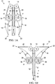
- FIGS. 1A and IB A crossbow 10 in accordance with one embodiment is generally depicted in FIGS. 1A and IB.
- the crossbow 10 can include a stock 12, a pair of pulleys 14 (e.g., cams) rotatably coupled to the stock 12, and a pair of bow limbs 16.
- Each of the bow limbs 16 can be rotatably coupled with the stock 12 at a proximal end 18 such that the bow limbs 16 are rotatable with respect to the stock 12 about respective limb axes A1 between a relaxed position ( FIG.
- a bow string 20 can be attached to distal ends 22 of the bow limbs 16 and routed from the distal ends 22, around the pulleys 14, and around a stop portion 24 ( FIG. 1A ).
- the bow string 20 can include a nocking portion 26 that is routed around the stop portion 24. It is to be appreciated than any of a variety of suitable alternative stocks can be provided for use with the bow limbs 16.
- a spring 28 can be disposed at each of the distal ends 22 of the bow limbs 16 and can facilitate rotatable coupling of the bow limbs 16 to the stock 12.
- the springs 28 can be configured to bias the bow limbs 16 into the relaxed position.
- a nock of an arrow e.g., 136 in FIG. 2A
- the arrow can be laid between the springs 28 to load the arrow into the crossbow 10.
- the arrow can then be pulled rearwardly (e.g., in the direction of arrow P) which can pull the bow limbs 16 into the loaded position, and a catch (e.g., 140 in FIG 2A ) can hold the nocking portion 26 in position.
- a user can pull a trigger (e.g., 142 in FIG 2A ) which releases the catch.
- the springs 28 can pull the bow limbs 16 towards the relaxed position which can pull the nocking portion 26 forwardly (in the opposite direction as arrow P) which can fire the arrow.
- the springs 28 can be provided in a torsion spring type arrangement.
- one of the springs 28 is shown to include a spindle 30 that is flexibly coupled with an outer collar 32 by a flexible body 34.
- the flexible body 34 can comprise an elastomeric material, such as a vulcanized isoprene rubber (e.g., natural rubber), for example.
- the spindle 30 can be rigidly coupled with the stock 12 and the outer collar 32 can be rigidly coupled with the rest of the bow limb 16. When the bow limb 16 is moved from the relaxed position to the loaded position, the spindle 30 pivots with respect to the outer collar 32 (in the direction of arrow T).
- the flexible body 34 opposes this pivoting, thus biasing the bow limb 16 towards the relaxed position.
- the flexible body 34 facilitates pivoting of the spindle 30 (in a direction opposite arrow T) to pull the bow limb 16 towards the relaxed position, thus firing the arrow.
- the springs 28 can be provided in any of a variety of arrangements that facilitate biasing of the bow limbs 16 towards the relaxed position.
- the rest of the bow limbs 16 can be formed of a material that is less expensive, more durable, and easier to make that than CFRP and/or fiberglass, such as high strength steel (HSS).
- the elastomeric material used for the springs 28 and the HSS used for the bow limbs 16 can be more cost effective and easier to manufacture than conventional CFRP and/or fiberglass bow limbs.
- the material properties of the elastomeric material used for the springs 28 and the HSS used for the bow limbs 16 can be more easily controlled during manufacturing. As a result, the performance of the springs 28 and the bow limbs 16 are more predictable, which can reduce or eliminate the need to tune or match performance characteristics of the bow limbs as is oftentimes the case with CFRP and/or fiberglass bow limbs.
- the effectiveness of the springs 28 can be affected by the shape of the flexible material as well as two of its material properties - the maximum allowable stress ( ⁇ ) and the Stiffness modulus (E).
- the maximum allowable stress ( ⁇ ) can be described as the amount of load that the flexible/elastic material of the springs 28 can support before breaking.
- the Stiffness modulus (E) can be described as the amount of deformation of the material upon the application of an applied load.
- the energy storage capacity of a spring can be defined as the Specific Strain Energy (SSE).
- SSE Specific Strain Energy
- FIG. IF a plot is depicted showing the relationship between the pull distance (d) and the pull force (P) of the bow string 20 as a result of the springs 28 as compared with a simple spring.
- the force required to pull the bow string 20 increases.
- the force required to pull the bow string 20 stays substantially the same and then decreases as the nocking portion 26 ( FIGS. 1A and 1B ) approaches the catch. This eventual decrease in required force is called detente and can reduce fatigue in a user.
- the force on the string of a crossbow with a simple string increases through the travel of the spring rearwardly which can encourage fatigue in a user.
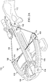
- FIG. 2A illustrates an alternative embodiment of a crossbow 110 that is similar to or the same as in many respects as the crossbow 10 of FIGS. 1A-1E .
- the crossbow 110 can have a stock 112, a pair of pulleys 114, a pair of bow limbs 116, and a bow string 120.
- a proximal end 118 of each of the bow limbs 116 can be rigidly coupled with the stock 112, and the pulleys 114 can be disposed at respective distal ends 122 of the bow limbs 116.
- the bow string 120 can be routed around the pulleys 114.
- a nock 136 of an arrow 138 can be engaged with a nocking portion 126 of the bow string 120.
- the arrow 138 can then be pulled rearwardly which can pull the bow limbs 16 into the loaded position as shown in FIG. 2A .
- the nocking portion 126 of the bow string 120 can engage a catch 140 which can hold the nocking portion 126 in position until released by a trigger 142.
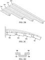
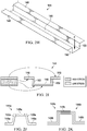
- each of the bow limbs 116 can be formed of a plurality of leaf plates 144 that can have different lengths (as shown in FIGS. 2B and 2G ) and can be stacked on top of each other (as shown in FIGS. 2C and 2G ) to form each bow limb 116.
- the leaf plates 144 can be stacked in such a manner that the outermost leaf plate 144 (the leaf plate 144 that extends along the front most portion of the crossbow 110 when the bow limbs 116 are in the relaxed position) is the longest and overlies shorter leaf plates 144.
- Each of the leaf plates 144 is arranged such that it is shorter than the one that overlies it.
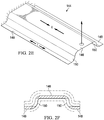
- Each of the leaf plates 144 can have a cross-sectional profile that resembles a top hat. More particularly, each of the leaf plates 144 can have an upper portion 146 and a pair of lower edge portions 148 that are spaced from each other and substantially parallel with each other. A pair of wall portions 150 can extend between the upper portion 146 and the pair of lower edge portions 148. The pair of wall portions 150 can be spaced from each other and substantially parallel with each other. This top-hat type arrangement provides more material in high stress locations than in low stress locations (see FIG. 21 ). It is to be appreciated that each of the leaf plates 144 can be configured to be slightly smaller or larger than the adjacent leaf plates 144 to accommodate stacking (see FIG. 2D ). Although the bow limbs 116 are shown in FIG.
- the bow limbs 116 can alternatively be arranged in a reverse orientation such that the pair of lower edge portions 148 extend along the front most portion of the crossbow 110.
- the leaf plates 144 can be formed of a metal or metal alloy such as high strength steel (HSS), Beryllium Copper, Phosphor Bronze, and/or Titanium, for example. In one embodiment, all of the leaf plates 144 can be formed of the same material while in another embodiment, some or all of the leaf plates can be formed of different material. It is to be appreciated that by forming the leaf plates 144 from a metal or metal alloy, the bow limbs 116 can be less expensive, more durable, and easier to make than CFRP and/or fiberglass. In addition, the bow limbs 116 can be more cost effective, easier to manufacture, and the material properties can be more easily controlled during manufacturing.
- HSS high strength steel
- the bow limbs 116 can be less expensive, more durable, and easier to make than CFRP and/or fiberglass.
- the bow limbs 116 can be more cost effective, easier to manufacture, and the material properties can be more easily controlled during manufacturing.
- FIGS. 2J and 2K illustrate alternative embodiments of leaf plates 144a and 144b, respectively that are similar to or the same as in many respects as the leaf plates 144 of FIGS. 2A-2J .
- the leaf plate 144a of FIG. 2J has wall portions 150a that are angled with respect to an upper portion 146a and lower edge portions 148a.
- the leaf plates 144b of FIG. 2K only have one of each of an upper portion 146b, a lower edge portion 148b, and a wall portion 150b.
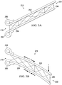
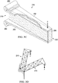
- FIGS. 3A-3D illustrate an alternative embodiment of a bow limb 216 that is similar to or the same as in many respects as the bow limbs 116 of FIGS. 2A-2I .
- the bow limb 216 can have a proximal end 218 that is configured to be rigidly coupled with a stock (not shown), and a pulley (not shown) can be disposed at a distal end 222 of the bow limbs 216.
- the bow limb 216 can include an upper plate member 252, a lower plate member 254, with a cushioning member 256 sandwiched in between Each of the upper and lower plate members 252, 254 can include respective mounting sleeves 258, 260 that facilitate mounting of the bow limb 216 to the stock (e.g., with pins).
- the upper and lower plate members 252, 254 can be formed of a metal or metal alloy such as high strength steel (HSS), Beryllium Copper, Phosphor Bronze, and/or Titanium, for example.
- HSS high strength steel
- the upper and lower plate members 252, 254 can be formed of the same material while in another embodiment, the upper and lower plate members 252, 254 can be formed of different material.
- the cushioning member 256 can be formed of an elastomeric material, such as a vulcanized isoprene rubber (e.g., natural rubber), for example.
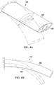
- FIGS. 4A-4D illustrate an alternative embodiment of a bow limb 316 that is similar to or the same as in many respects as the bow limbs 16, 116 of FIGS. 1A-1E and 2A-2J , respectively.
- the bow limb 316 comprises an outer sheath 360 and an inner elongate rib member 362.
- the outer sheath 360 and inner elongate RIB member 362 can deform as the bow limb 316 moves towards the loaded position. More particularly, the inner elongate rib member 362 can collapse into a substantially flat arrangement (i.e., buckle) which can result in detente (e.g., letdown) during pullback.
- the inner elongate rib member 362 can also control the buckling of the outer sheath 360 so as to provide a desirable pull characteristic during pullback. It is to be appreciated that examples of conventional crossbow arrangements are provided in Appendix A. Appendix B illustrates various details (including some forces and moments) for different crossbow and/or bow limb arrangements.
- FIG. 5 illustrates an alternative embodiment of a crossbow 410 that is similar to or the same as in many respects as the crossbow 110 of FIG. 2A .
- the crossbow 410 includes a stock 412 and a pair of bow limbs 416 pivotally coupled with the stock 412.
- the bow limbs 416 are coupled together with a resilient member 464 that facilitates biasing of the bow limbs 416 into the relaxed position.
- a resilient member 464 that facilitates biasing of the bow limbs 416 into the relaxed position.
- proximal ends 418 are drawn away from each other (in the direction of arrow C) thereby stretching the resilient member 464 such that the resilient member 464 biases the bow limbs 416 into the relaxed position.
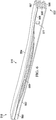
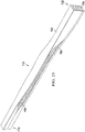
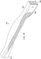
- FIGS. 6-12 illustrate an alternative embodiment of a bow limb 516 that extends between a proximal end 518 and a distal end 522.
- the bow limb 516 includes an outer elongate member 552, an inner elongate member 554, and a core member 556 sandwiched between the outer elongate member 552 and the inner elongate member 554.
- the outer and inner elongate members 552, 554 can be formed of hardened metal
- the core member 556 can be formed of a rubber.
- the core member 556 can be coupled with respective interior surfaces 566, 567 of the outer elongate member 552 and the inner elongate member 554 such that the outer elongate member 552 and the inner elongate member 554 are coupled together via the core member 556.
- the core member 556 can be coupled to the respective interior surfaces 566, 567 of the outer and inner elongate members 552, 554 with adhesive or any of a variety of other suitable attachment methods.
- the outer elongate member 552 and the inner elongate member 554 can interface with each other at a seam 568.
- the outer and inner elongate members 552, 554 can be detached from each other along the seam 568 such that the outer elongate member 552 and the inner elongate member 554 are permitted to slide relative to each other when the bow limb 516 is bent (as will be described in further detail below with respect to FIGS. 24 and 26 ).
- the outer and inner elongate members 552, 554 can cooperate to define a lateral opening 569 that is disposed between the proximal end 518 and the distal end 522 and through which the core member 556 is exposed.
- the lateral opening 569 allows for the outer and inner elongate members 552, 554 to compress together at the lateral opening 569 without interfering with each other when the bow limb 516 is bent (as will be described in further detail below with respect to FIGS. 24 and 26 ).
- outer and inner elongate members 552, 554 can be formed of other metals, such as beryllium, copper, and/or titanium or any of a variety of other suitable materials that are stiffer than the material of the core member 556. It is also to be appreciated that the core member 556 can be formed of any of a variety of elastomeric materials and/or other suitable materials that are less stiff than the material of the outer and inner elongate members 552, 554.
- the outer elongate member 552 can be substantially c-shaped at each of the proximal end 518 and the distal end 522.
- the outer elongate member 552 can have a central member 570 and a pair of leg members 572 that extend from and cooperate with the central member 570 to define a c-shaped portion at each of the proximal and distal ends 518, 522.
- the inner elongate member 554 can be substantially c-shaped at the proximal end 518.
- the inner elongate member 554 can have a central member 574 and a pair of leg members 576 that extend from and cooperate with the central member 574 to define a c-shaped portion at the proximal end 518.
- the core member 556 can be disposed within each of the c-shaped portions when attached to the outer and inner elongate members 552, 554.
- the core member 556 can be coupled with the respective interior surfaces 566, 567 located at the central members 570, 574 of the respective outer and inner elongate members 552, 554.
- the core member 556 can be detached from the respective interior surfaces 566, 567 (e.g., devoid of adhesive) of the outer and inner elongate members 552, 554 at the respective leg members 572, 576.
- the outer elongate member and the inner elongate member might be a substantially flat steel member that is substantially devoid of any c-shaped portions (see, for example, FIGS. 3A-3C ).
- the distal end 522 of the bow limb 516 can define a through hole 577 that facilitates rotatable coupling of a cam (e.g., 514 in FIG. 13 ) to the distal end 522 of the bow limb 516.
- the through hole 577 can extend through each of the leg members 572 of the outer elongate member 552 and through the core member 556.
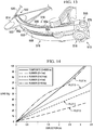
- FIG. 13 a portion of a right side of a crossbow is shown that incorporates a pair of the bow limbs 516 illustrated in FIGS. 6-12 .
- the proximal ends 518 of each of the bow limbs 516 can be coupled to a front end 513 of the crossbow with a clamp 578.
- a cam 514 can be rotatably coupled to the distal ends 522 of the pair of bow limbs 516 (e.g., via the through holes 577) and a bow string 520 can be routed around the cam 514 which can facilitate firing of a bolt (e.g., an arrow) from the crossbow.
- a bolt e.g., an arrow
- FIG. 13 Another pair of the bow limbs 516 can be incorporated into a left side of the crossbow that is effectively a mirror image of what is shown in FIG. 13 and that cooperates with the bow limbs 516 on the right side to facilitate firing of a bolt from the crossbow.
- the bow limbs 516 can be arranged on the crossbow such that the outer elongate members 552 of one pair of bow limbs 516 faces away from the outer elongate members 552 of the other pair of bow limbs 516, and the inner elongate members 554 of one pair of bow limbs 516 faces the inner elongate members 554 of the other pair of bow limbs 516.
- a bolt is loaded into the crossbow and pulled rearwardly (e.g., in the direction of arrow P in FIG 1A )
- the bow limbs 516 can be bent into a loaded position.
- the bow limbs 516 can perform as well or better than conventional fiber reinforced plastic (FRP) bow limbs and can thus serve as a cost effective replacement for those conventional bow limbs (e.g., during manufacturing of a crossbow or as a retrofit for an existing cross bow).
- FRP fiber reinforced plastic
- the materials used to manufacture the outer and inner elongate members 552, 554 and the core member 556 e.g., steel and rubber, respectively
- the manufacturing process for those materials is less complicated than FRP, and in some cases, can be simple enough for a cross bow manufacturer to perform rather than relying on a third party bow limb manufacturer, as is typically the case with manufacturing bow limbs out of FRP.
- the materials and manufacturing process of the bow limbs 516 can yield more predictable results.
- the characteristics of the materials that might affect the performance of the bow limbs e.g., thickness, stiffness, imperfections
- FRP the performance of the bow limbs
- the overall structure of the bow limbs is such that the performance of the bow limbs is less susceptible to being affected by slight variability in the material characteristics. This consistency among the bow limbs can alleviate the need to test each bow limb and match it with a similar performing bow limb (e.g., sorting), as is typical with FRP bow limbs, which can be time consuming and inefficient.
- the particular configuration of the outer and inner metal layers e.g., shape, thickness, and length
- the configuration of the elastomeric material could then be designed (e.g., engineered) to achieve a desired stiffness (e.g., weight divided by distance) for the bow limb 516.
- a desired stiffness e.g., weight divided by distance
- bow limbs e.g., 516) with different stiffnesses can be provided to accommodate the various skill levels of users.
- FIG. 14 a plot is illustrated that depicts one example of the relationship between a load provided to the distal ends 522 of the bow limb 516 (in pounds of force) and the resulting deflection of the bow limb 516 (in inches) for various modulus values of the core member 556 as compared to a conventional FRP bow limb.
- the response of the conventional FRP bow limb is shown in dashed lines.
- the response of the bow limb 516 is shown by the other plots on the graph.
- the plot can be understood to illustrate how the modulus of the core member 556 can be selected to match the response of the conventional FRP bow limb as well as how different modulus values affect the response of the bow limb 516 without changing the outer and inner elongate members 552, 554.
- the plot can be also be understood to illustrate how different modulus values can be selected for the core member 556 of the bow limb 516 to provide a different response (e.g., for users of different skill levels).
- a core member 556 having a modulus of about 10 KSI can have a response (identified as Plot A) that closely resembles the response of the conventional FRP bow limb.
- Plot A a response that closely resembles the response of the conventional FRP bow limb.
- the modulus of the core member 556 is decreased, the relationship between the load provided to the distal ends 522 of the bow limb 516 and the resulting deflection of the bow limb 516 decreases.
- the response of the bow limb 516 to load (identified as Plot B) is still substantially constant (e.g., the slope of the plot is substantially straight), however, the bow limb 516 does not deflect as much under the same load as the bow limb 516 having a core member 556 with a modulus value of about 10 KSI.
- the response of the bow limb 516 (identified as Plot C) to load is still substantially constant (e.g., the slope of the plot is substantially straight), however, the bow limb 516 does not deflect as much under the same load as the bow limb 516 having a core member 556 with a modulus value of about 4 KSI.
- the response of the bow limb 516 (identified as Plot D) to load is still substantially constant (e.g., the slope of the plot is substantially straight), however, the bow limb 516 does not deflect as much under the same load as the bow limb 516 having a core member 556 with a modulus value of about 2.5 KSI.
- the plot illustrated in FIG. 14 can also be understood to illustrate how manufacturing tolerances in the modulus of the core member 556 (e.g., material characteristics) do not significantly adversely affect the performance of the bow limb 516.
- the modulus of the core member 556 might vary slightly (along the length of the core member 556) due to manufacturing tolerances.
- these variations in the modulus are typically within the range of between about 0.1 and about 10 PSI and thus not significant enough (relative to plots B-D) to adversely affect the overall performance of the bow limb 516.
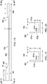
- FIGS. 15-22 illustrate an alternative embodiment of a bow limb 616 that is similar to or the same in many respects as the bow limb 316 illustrated in FIGS. 6-13 .
- the bow limb 616 can extend between a proximal end 618 and a distal end 622 and can include an outer elongate member 652, an inner elongate member 654, and a core member 656 that is sandwiched between the outer and inner elongate members 652, 654.
- the core member 656 can be coupled with respective interior surfaces 666, 667 located at central members 670, 674 of the respective outer and inner elongate members 652, 654.
- the core member 656 can be detached from the respective interior surfaces 666, 667 (e.g., devoid of adhesive) of the outer and inner elongate members 652, 654 at respective leg members 672, 676.
- the outer elongate member 652 is shown to include a proximal end portion 680, a distal end portion 681, and a central portion 682 disposed between the proximal and distal end portions 680, 681.
- the outer elongate member 652 can have a length L1.
- the proximal end portion 680 can have a length L2
- the distal end portion 681 can have a length L3, and the central portion 682 can have a thickness T1.
- the length L1 can be about 11 inches
- the length L2 can be about 1.5 inches
- the length L3 can be about 1.5 inches
- the thickness T1 can be about 0.062 inches.
- the outer elongate member 652 is shown to include a proximal transition portion 683 and a distal transition portion 684.
- the proximal transition portion 683 can extend between the proximal end portion 680 and the central portion 682 and is shown to have a radius of curvature R1.
- the distal transition portion 684 can extend between the distal end portion 681 and the central portion 682 and is shown to have a radius of curvature R2.
- the radii of curvature R1 and R2 can be about 3 inches. It is to be appreciated that the area between the proximal end portion 680 and the distal end portion 681 can at least partially define a lateral opening (e.g., 369) for the bow limb 616.
- the distal end portion 682 is shown to have a central member 670a and a pair of leg members 672a that extend therefrom.
- the central member 670a can have a length L4, the leg members 672a can have a height HI a thickness T2.
- the length L4 can be about 0.531 inches
- the height HI can be about 0.5 inches
- the thickness T2 can be about 0.062 inches.
- the proximal end portion 680 is shown to have a central member 670b and a pair of leg members 672b that extend therefrom.
- the central member 670b can have a length L5, the leg members 672b can have a height H2 a thickness T3.
- the length L5 can be about 0.531 inches
- the height H2 can be about 0.219 inches
- the thickness T3 can be about 0.062 inches.
- the inner elongate member 654 is shown to include a proximal end portion 685 and a distal end portion 686.
- the inner elongate member 654 can have a length L6.
- the proximal end portion 685 can have a length L7 and the distal end portion 686 can have a thickness T4.
- the length L6 can be about 11 inches
- the length L7 can be about 1.5 inches
- the thickness T4 can be about 0.062 inches.
- the inner elongate member 654 is shown to include a proximal transition portion 687 that extends between the proximal end portion 685 and the distal end portion 686.
- the proximal transition portion 687 is shown to have a radius of curvature R3. In one embodiment, the radius of curvature R3 can be about 3 inches.
- the proximal end portion 685 is shown to have a central member 672 and a pair of leg members 676 that extend therefrom.
- the central member 672 can have a length L8, the leg members 676 can have a height H3 and a thickness T5.
- the length L8 can be about 0.531 inches
- the height H3 can be about 0.219 inches
- the thickness T5 can be about 0.062 inches. It is to be appreciated that the dimensions of the bow limb 616 described above should be understood to be one example of many different dimensions that are contemplated.
- FIGS. 23 and 24 illustrate another alternative embodiment of a bow limb 716 that is similar to or the same in many respects as the bow limb 316 illustrated in FIGS. 6-13 .
- the bow limb 716 can extend between a distal end 718 and a proximal end 722 and can include an outer elongate member 752, an inner elongate member 754, and a core member 756 that is sandwiched between the outer and inner elongate members 752, 754.
- FIG. 23 and 24 illustrate another alternative embodiment of a bow limb 716 that is similar to or the same in many respects as the bow limb 316 illustrated in FIGS. 6-13 .
- the bow limb 716 can extend between a distal end 718 and a proximal end 722 and can include an outer elongate member 752, an inner elongate member 754, and a core member 756 that is sandwiched between the outer and inner elongate members 752, 754.
- the outer and inner elongate members 752, 754 can compress together at a lateral opening 769, and the inner elongate member 754 can slide laterally with respect to the outer elongate member 752 such that a portion of the inner elongate member 754 can extend beyond the outer elongate member 752.
- the core member 756 can become deformed where the inner elongate member 754 extends beyond the outer elongate member 752 which can allow for such sliding of the inner elongate member 754 relative to the outer elongate member 752.
- FIGS. 25 and 26 illustrate yet another alternative embodiment of a bow limb 816 that is similar to or the same in many respects as the bow limb 716 illustrated in FIGS. 23 and 24 .
- the bow limb 816 can extend between a distal end 818 and a proximal end 822 and can include an outer elongate member 852, an inner elongate member 854, and a core member 856 that is sandwiched between the outer and inner elongate members 852, 854.
- FIG. 27 a plot is illustrated that depicts one example of the relationship between a tip force (e.g., load) provided to the distal ends 722, 822 of the respective bow limbs 716, 816 (in pounds of force) and the resulting tip deflection of the bow limbs 716, 816 (in inches) illustrated in FIGS. 23-26 .
- a tip force e.g., load
- FIG. 28 illustrates yet another alternative embodiment of a bow limb 916 that is similar to or the same in many respects as the bow limb 316 illustrated in FIGS. 6-13 .
- the bow limb 916 can extend between a distal end 918 and a proximal end 922 and can include an outer elongate member 952, an inner elongate member 954, and a core member 956 that is sandwiched between the outer and inner elongate members 952, 954.
- FIG. 29 illustrates still yet another alternative embodiment of a bow limb 1016 that is similar to or the same in many respects as the bow limb 316 illustrated in FIGS. 6-13 .
- the bow limb 1016 can extend between a proximal end 1018 and a distal end 1022 and can include an outer elongate member 1052, an inner elongate member 1054, and a core member 1056 that is sandwiched between the outer and inner elongate members 1052, 1054.
- the outer elongate member 1052 and the inner elongate member 1054 can be formed together as a one piece construction that defines a seam 1068.
- FIG. 30 illustrates still yet another alternative embodiment of a pair of bow limbs 1116 that are each similar to or the same in many respects as the bow limb 316 illustrated in FIGS. 6-13 .
- each bow limb 1116 can include a proximal end 1118.
- the proximal end 1118 can have a flared profile (e.g., a width that increases as it approaches the proximal end 1118) that can alleviate the possibility of the bow limbs 1116 being pulled away from the clamp 1178 when the bow limbs 1116 are bent into a firing position.
- FIG. 31 illustrates still yet another alternative embodiment of a pair of bow limbs 1216 that are each similar to or the same in many respects as the bow limb 316 illustrated in FIGS. 6-13 .
- each bow limb 1216 can include a proximal end 1218, a distal end 1222, and a core member 1256.
- each bow limb 1216 can include a hinge member 1288 that can facilitate pivoting of the distal end 1222 relative to the proximal end 1218.
- Each core member 1256 can also include an embedded spring 1290 that facilitates biasing of the associated bow limb 1216 into a straightened position.
- each embedded spring 1290 can be in a relaxed state (see FIG. 32 ).
- each embedded spring 1290 can be in a bent state (see FIG. 33 ) which can facilitate biasing of the associated bow limb 1216 into the straightened position.
Landscapes
- Engineering & Computer Science (AREA)
- General Engineering & Computer Science (AREA)
- Orthopedics, Nursing, And Contraception (AREA)
- Golf Clubs (AREA)
- Magnetic Resonance Imaging Apparatus (AREA)
- Toys (AREA)
Claims (6)
- Wurfarm (516) für einen Bogenschießbogen (10), wobei der Wurfarm (516) Folgendes umfasst:ein äußeres längliches Element (552), das aus einem ersten Material ausgebildet ist und eine Innenoberfläche (566) und eine Außenoberfläche umfasst;ein inneres längliches Element (554), das aus einem zweiten Material ausgebildet ist und eine Innenoberfläche (567) und eine Außenoberfläche umfasst; undein Kernelement (556), das aus einem dritten Material ausgebildet ist und zwischen dem äußeren länglichen Element (552) und dem inneren länglichen Element (554) schichtweise angeordnet ist, wobei das Kernelement (556) mit wenigstens einem Abschnitt jeder der Innenoberflächen (566, 567) des äußeren länglichen Elements (552) und des inneren länglichen Elements (554) gekoppelt ist; wobei:das äußere längliche Element (552) und das innere längliche Element (554) konfiguriert sind, um sich relativ zueinander zu bewegen, wenn der Wurfarm (516) gebogen wird; unddas erste Material und das zweite Material jeweils steifer als das dritte Material sind;der Wurfarm (516) dadurch gekennzeichnet ist, dass das äußere längliche Element (552) und das innere längliche Element (554) jeweils ein zentrales Element (570, 574) und ein Paar Schenkelelemente (572, 576) umfassen, die sich aus dem zentralen Element (570, 574) erstrecken und mit diesem zusammenwirken, um einen c-förmigen Abschnitt zu definieren.
- Wurfarm nach Anspruch 1, wobei:das erste Material und das zweite Material hochfesten Stahl, Berylliumkupfer und/oder Titan umfassen; unddas dritte Material ein elastomerisches Material umfasst.
- Wurfarm nach Anspruch 1 oder 2, wobei:das Kernelement (556) mit der Innenoberfläche (566, 567) gekoppelt ist, die sich an dem zentralen Element jedes des äußeren länglichen Elements (552) und des inneren länglichen Elements (554) befindet; unddas Kernelement (556) von den Innenoberflächen entkoppelt ist, die sich an den Schenkelelementen (572, 576) jedes des äußeren länglichen Elements (552) und des inneren länglichen Elements (554) befinden.
- Wurfarm (616) für einen Bogenschießbogen (10) nach einem der vorhergehenden Ansprüche, wobei der Wurfarm (616) Folgendes umfasst:ein äußeres längliches Element (652), das aus einem ersten Material ausgebildet ist und ein zentrales Element (670) und ein Paar Schenkelelemente (672) umfasst, die sich aus dem zentralen Element (670) erstrecken;ein inneres längliches Element (654), das aus einem zweiten Material ausgebildet ist und ein zentrales Element (674) und ein Paar Schenkelelemente (676) umfasst, die sich aus dem zentralen Element (674) erstrecken; undein Kernelement (656), das aus einem dritten Material ausgebildet ist und zwischen dem äußeren länglichen Element (652) und dem inneren länglichen Element (654) schichtweise angeordnet ist;wobei das Kernelement (656) mit dem zentralen Element (670) des äußeren länglichen Elements (652) und dem zentralen Element (674) des inneren länglichen Elements (654) gekoppelt ist;das Kernelement (656) von dem Paar Schenkelelementen (672) des äußeren länglichen Elements (652) und dem Paar Schenkelelementen (676) des inneren länglichen Elements (654) entkoppelt ist;das äußere längliche Element (652) und das innere längliche Element (654) konfiguriert sind, um sich relativ zueinander zu bewegen, wenn der Wurfarm (616) gebogen wird; unddas erste Material und das zweite Material jeweils steifer als das dritte Material sind.
- Wurfarm (516) für einen Bogenschießbogen (10) nach einem der vorhergehenden Ansprüche, wobei der Wurfarm (516) Folgendes umfasst:ein äußeres längliches Element (552), das aus einem ersten Material ausgebildet ist und eine Innenoberfläche (566) und eine Außenoberfläche umfasst;ein inneres längliches Element (554), das aus einem zweiten Material ausgebildet ist und eine Innenoberfläche (567) und eine Außenoberfläche umfasst; undein Kernelement (556), das aus einem dritten Material ausgebildet ist und zwischen dem äußeren länglichen Element (552) und dem inneren länglichen Element (554) schichtweise angeordnet ist, wobei das Kernelement (556) mit wenigstens einem Abschnitt jeder der Innenoberflächen (566, 567) des äußeren länglichen Elements (552) und des inneren länglichen Elements (554) gekoppelt ist; wobei das äußere längliche Element (552) und das innere längliche Element (554) konfiguriert sind, um sich relativ zueinander zu bewegen, wenn der Wurfarm (516) gebogen wird; und das erste Material und das zweite Material jeweils steifer als das dritte Material sind; der Wurfarm dadurch gekennzeichnet ist, dass das erste Material und das zweite Material hochfesten Stahl, Berylliumkupfer und/oder Titan umfassen; und das dritte Material ein elastomerisches Material umfasst.
- Bogenschießbogen, der den Wurfarm nach einem der vorhergehenden Ansprüche umfasst.
Applications Claiming Priority (2)
| Application Number | Priority Date | Filing Date | Title |
|---|---|---|---|
| US201662327035P | 2016-04-25 | 2016-04-25 | |
| PCT/US2017/029308 WO2017189510A1 (en) | 2016-04-25 | 2017-04-25 | Bow limb and archery bow using same |
Publications (3)
| Publication Number | Publication Date |
|---|---|
| EP3449200A1 EP3449200A1 (de) | 2019-03-06 |
| EP3449200A4 EP3449200A4 (de) | 2019-11-27 |
| EP3449200B1 true EP3449200B1 (de) | 2021-04-21 |
Family
ID=60160082
Family Applications (1)
| Application Number | Title | Priority Date | Filing Date |
|---|---|---|---|
| EP17790232.7A Active EP3449200B1 (de) | 2016-04-25 | 2017-04-25 | Bogenglied und bogen mit einem solchen bogenglied |
Country Status (5)
| Country | Link |
|---|---|
| US (1) | US10627185B2 (de) |
| EP (1) | EP3449200B1 (de) |
| KR (1) | KR102301845B1 (de) |
| CA (1) | CA3022277C (de) |
| WO (1) | WO2017189510A1 (de) |
Families Citing this family (18)
| Publication number | Priority date | Publication date | Assignee | Title |
|---|---|---|---|---|
| US9383159B2 (en) * | 2013-03-13 | 2016-07-05 | Ravin Crossbows, Llc | De-cocking mechanism for a bow |
| US12566042B2 (en) | 2013-12-16 | 2026-03-03 | Ravin Crossbows, Llc | Reduced length crossbow |
| US10712118B2 (en) | 2013-12-16 | 2020-07-14 | Ravin Crossbows, Llc | Crossbow |
| US12449224B2 (en) | 2013-12-16 | 2025-10-21 | Ravin Crossbows, Llc | Arrow assembly for a crossbow and method of using same |
| US12188740B2 (en) | 2013-12-16 | 2025-01-07 | Ravin Crossbows, Llc | Silent cocking system for a crossbow |
| US20190137212A1 (en) | 2013-12-16 | 2019-05-09 | Ravin Crossbows, Llc | Crossbow with Pulleys that Rotate Around Stationary Axes |
| US11428496B2 (en) * | 2016-04-25 | 2022-08-30 | Stress Engineering Services, Inc. | Limb having a core member and an archery bow including same |
| US11143483B2 (en) * | 2016-04-25 | 2021-10-12 | Stress Engineering Services, Inc. | Limb having a core member and an archery bow including same |
| US10989491B2 (en) * | 2017-02-10 | 2021-04-27 | Mcp Ip, Llc | Archery bow with wide ratio limb |
| US10612882B2 (en) | 2017-11-01 | 2020-04-07 | Mcp Ip, Llc | Archery bow with stacked limbs |
| US11226166B2 (en) * | 2018-10-24 | 2022-01-18 | Mcp Ip, Llc | Archery bow limb assembly |
| US20200208934A1 (en) * | 2018-12-27 | 2020-07-02 | Samuel L. Guiffrida | Bow |
| WO2021211216A1 (en) * | 2020-04-17 | 2021-10-21 | Stress Engineering Services, Inc. | Limb having a core member and an archery bow including same |
| US11927421B1 (en) * | 2021-06-17 | 2024-03-12 | Titus Gadwin Watts | Long bow with tensioners |
| EP4483121A4 (de) * | 2022-02-25 | 2026-02-25 | Mcp Ip Llc | Bogenbogen-schenkelkonstruktion |
| WO2023164165A1 (en) * | 2022-02-25 | 2023-08-31 | Mcp Ip, Llc | Archery bow limb construction |
| US11486772B1 (en) * | 2022-04-25 | 2022-11-01 | Stress Engineering Services, Inc. | Transducer assemblies and methods |
| US12460892B2 (en) | 2023-12-06 | 2025-11-04 | Ravin Crossbows, Llc | Crossbow with trigger box |
Family Cites Families (47)
| Publication number | Priority date | Publication date | Assignee | Title |
|---|---|---|---|---|
| US650411A (en) | 1899-04-25 | 1900-05-29 | John G L Myers | Crossbow-gun. |
| US785050A (en) | 1903-11-16 | 1905-03-14 | Samuel L Saunders | Bow-gun. |
| US1724387A (en) | 1927-10-28 | 1929-08-13 | American Fork & Hoe Co | Bow for archery |
| US1877273A (en) | 1927-10-28 | 1932-09-13 | American Fork & Hoe Co | Bow |
| US2361068A (en) | 1943-04-08 | 1944-10-24 | Sollid Erik | Archery bow |
| US2664079A (en) | 1949-01-19 | 1953-12-29 | Harry F Lake | Metal archer's bow |
| US2665678A (en) | 1950-04-21 | 1954-01-12 | Bear Archery Company | Composite archery bow |
| US2831674A (en) | 1950-12-27 | 1958-04-22 | Pacific Car & Foundry Co | Spring suspension |
| US2736309A (en) | 1952-06-09 | 1956-02-28 | Hoffman Robert John | Archery bow |
| US2815015A (en) | 1956-01-09 | 1957-12-03 | Giacomo Ernest Louis De | Archery bow |
| US2945488A (en) | 1956-09-04 | 1960-07-19 | Cravotta Brothers Inc | Composite bow for archers |
| US3015327A (en) * | 1959-09-04 | 1962-01-02 | Joseph F Lightcap | Archery bows |
| US3581729A (en) | 1969-06-02 | 1971-06-01 | Leland L Jones | Crossbow structure |
| US3757762A (en) | 1970-04-20 | 1973-09-11 | Plas Steel Products Inc | Archery bow with removable inserts to vary draw force |
| US3625193A (en) | 1970-05-21 | 1971-12-07 | James R Palma | Archery bow with variable bow-tensioning device |
| US3674001A (en) | 1970-12-03 | 1972-07-04 | Hit Archery Co Inc | Archery bow in combination with draw force multiplying means |
| US3850156A (en) | 1973-06-01 | 1974-11-26 | F Eicholtz | Composite archery bow |
| US4712533A (en) | 1986-05-22 | 1987-12-15 | Cruise Billy J | High-speed bow limbs |
| DE3723053A1 (de) | 1987-07-11 | 1989-01-19 | Kernforschungsz Karlsruhe | Wurf- oder federarm |
| US4819608A (en) | 1987-08-24 | 1989-04-11 | Hoyt/Easton Archery Co. | Archery bow limb constructed of syntactic foam |
| US5165382A (en) | 1991-02-07 | 1992-11-24 | Saxon International, Inc. | Power-variable bow |
| US5454361A (en) | 1993-05-10 | 1995-10-03 | Bronnert; Herve X. | Sequential bow |
| US5373831A (en) | 1993-06-03 | 1994-12-20 | Cushman; William B. | Compound bow with high power and extreme let-off |
| JP3027909B2 (ja) | 1994-04-22 | 2000-04-04 | ヤマハ株式会社 | 洋 弓 |
| US5657739A (en) | 1995-12-20 | 1997-08-19 | Precision Shooting Equipment, Inc. | Archery bow with reinforced limbs |
| US5881704A (en) | 1997-04-17 | 1999-03-16 | High Country Archery, Inc. | Archery bow limb and method |
| DE19818000A1 (de) | 1997-12-19 | 1999-06-24 | Herbert Suppan | Bogen mit Wurfarmen |
| KR200213948Y1 (ko) | 2000-09-08 | 2001-02-15 | 박경래 | 양궁날개 |
| US6718962B2 (en) | 2002-07-15 | 2004-04-13 | A&H Archery, Llc | Archery bow and limbs therefor |
| US20040077440A1 (en) * | 2002-10-18 | 2004-04-22 | Len Gregory Kronfeld | Archery bow limb construction with or without built in limb dampeners |
| US6932071B2 (en) | 2003-12-30 | 2005-08-23 | Sop Services, Inc. | Method for manufacturing ribbed archery bow limb portions and the ribbed archery bow limb portions produced thereby |
| US7025051B1 (en) | 2004-11-09 | 2006-04-11 | Sop Services, Inc. | Double constraint archery bow limb locating system |
| KR100612608B1 (ko) | 2005-05-18 | 2006-08-14 | 박경래 | 양궁날개용 코어 |
| US7438069B2 (en) | 2006-01-19 | 2008-10-21 | Mathew A. McPherson | Thermoplastic bow limb |
| US20080072887A1 (en) | 2006-09-21 | 2008-03-27 | Kyung-Rae Park | Limb for compound archery bow |
| US8079353B2 (en) | 2007-03-07 | 2011-12-20 | Prince Sports, Inc. | Archery bow having a multiple-tube structure |
| US8069847B2 (en) | 2008-04-01 | 2011-12-06 | Bear Archery Incorporated | Limb pocket spacer |
| KR20100004711U (ko) | 2008-10-29 | 2010-05-10 | 주식회사 삼익스포츠 | 활 날개 |
| KR20100088867A (ko) | 2009-02-02 | 2010-08-11 | 오승근 | 석궁이나 활에 장착할 고무줄 활시위와 레일과 노리쇠. |
| US9459066B2 (en) | 2009-04-28 | 2016-10-04 | John D. Evans | Compound bows with modified cams |
| US8635994B1 (en) | 2009-10-19 | 2014-01-28 | BowTech, Inc. | Multilayer composite limbs for an archery bow |
| US8807125B1 (en) | 2010-10-05 | 2014-08-19 | Plasticomp, Inc. | Three dimensionally fiber-reinforced composite riser and methods of making the same |
| US8991375B2 (en) | 2013-03-15 | 2015-03-31 | Mcp Ip, Llc | Crossbow cabling arrangement |
| US9091503B2 (en) | 2013-05-02 | 2015-07-28 | Robert Scott Howard | V-limb |
| US9310156B2 (en) | 2013-11-08 | 2016-04-12 | Todd Michael Whitaker | Projectile launcher |
| US9297604B1 (en) | 2014-04-02 | 2016-03-29 | Bear Archery, Inc. | Crossbow cam system |
| KR101643894B1 (ko) | 2014-12-11 | 2016-08-03 | 김용철 | 완구용 활 및 이를 이용한 석궁 |
-
2017
- 2017-04-25 CA CA3022277A patent/CA3022277C/en active Active
- 2017-04-25 EP EP17790232.7A patent/EP3449200B1/de active Active
- 2017-04-25 WO PCT/US2017/029308 patent/WO2017189510A1/en not_active Ceased
- 2017-04-25 KR KR1020187033022A patent/KR102301845B1/ko active Active
- 2017-04-25 US US16/096,468 patent/US10627185B2/en active Active
Non-Patent Citations (1)
| Title |
|---|
| None * |
Also Published As
| Publication number | Publication date |
|---|---|
| US20190120588A1 (en) | 2019-04-25 |
| EP3449200A1 (de) | 2019-03-06 |
| CA3022277A1 (en) | 2017-11-02 |
| EP3449200A4 (de) | 2019-11-27 |
| KR20180135933A (ko) | 2018-12-21 |
| WO2017189510A1 (en) | 2017-11-02 |
| US10627185B2 (en) | 2020-04-21 |
| CA3022277C (en) | 2022-05-24 |
| KR102301845B1 (ko) | 2021-09-14 |
Similar Documents
| Publication | Publication Date | Title |
|---|---|---|
| EP3449200B1 (de) | Bogenglied und bogen mit einem solchen bogenglied | |
| US11143483B2 (en) | Limb having a core member and an archery bow including same | |
| US11428496B2 (en) | Limb having a core member and an archery bow including same | |
| US7832387B1 (en) | Center-pivot limbs for an archery bow | |
| US8459244B2 (en) | Center-bearing limbs for an archery bow | |
| US20080254844A1 (en) | Link assembly with springs which can be extended and contracted and slider assembly for sliding type mobile phone having the link assembly | |
| US11898818B2 (en) | Projectile launching system | |
| US20150027425A1 (en) | Flexible cable guard for a compound archery bow | |
| US10018443B2 (en) | Bow for a crossbow | |
| US10345072B1 (en) | Flexible string damper | |
| US7331338B2 (en) | Biased move-away arrow rest | |
| US9212714B2 (en) | Fiber reinforced plastic spring | |
| DE202021101152U1 (de) | Schutzvorrichtung für eine Armbrust | |
| US20180171083A1 (en) | Fiber reinforced elastomeric sheets with tunable strain relationships | |
| US10077963B1 (en) | Double limb for arrow throwing device and arrow throwing device using the same | |
| WO2021211216A1 (en) | Limb having a core member and an archery bow including same | |
| US7311096B2 (en) | Method for manufacturing ribbed archery bow limb portions and the ribbed archery bow limb portions produced thereby | |
| US8104460B2 (en) | Sport bow and crossbow, with one or both limbs elastically deforming by deflection or simultaneous deflection and bending | |
| JP6535074B2 (ja) | リトラクティング機構 | |
| DE102004034730B4 (de) | Compoundbogen | |
| CN102939027B (zh) | 搬运行李包时吸收和最小化冲击的搬运设备 | |
| DE112008001241T5 (de) | Gewehrmagazin | |
| US20200408481A1 (en) | Archery device | |
| DE202024106962U1 (de) | Eine Pfeilhülsenstruktur zum Erkennen des Fehlens eines Pfeils und zum Verhindern einer Sehne | |
| US6536421B1 (en) | Archery bow |
Legal Events
| Date | Code | Title | Description |
|---|---|---|---|
| STAA | Information on the status of an ep patent application or granted ep patent |
Free format text: STATUS: THE INTERNATIONAL PUBLICATION HAS BEEN MADE |
|
| PUAI | Public reference made under article 153(3) epc to a published international application that has entered the european phase |
Free format text: ORIGINAL CODE: 0009012 |
|
| STAA | Information on the status of an ep patent application or granted ep patent |
Free format text: STATUS: REQUEST FOR EXAMINATION WAS MADE |
|
| 17P | Request for examination filed |
Effective date: 20181029 |
|
| AK | Designated contracting states |
Kind code of ref document: A1 Designated state(s): AL AT BE BG CH CY CZ DE DK EE ES FI FR GB GR HR HU IE IS IT LI LT LU LV MC MK MT NL NO PL PT RO RS SE SI SK SM TR |
|
| AX | Request for extension of the european patent |
Extension state: BA ME |
|
| DAV | Request for validation of the european patent (deleted) | ||
| DAX | Request for extension of the european patent (deleted) | ||
| A4 | Supplementary search report drawn up and despatched |
Effective date: 20191030 |
|
| RIC1 | Information provided on ipc code assigned before grant |
Ipc: F41B 5/10 20060101ALI20191024BHEP Ipc: F41B 5/00 20060101AFI20191024BHEP |
|
| GRAP | Despatch of communication of intention to grant a patent |
Free format text: ORIGINAL CODE: EPIDOSNIGR1 |
|
| STAA | Information on the status of an ep patent application or granted ep patent |
Free format text: STATUS: GRANT OF PATENT IS INTENDED |
|
| INTG | Intention to grant announced |
Effective date: 20201123 |
|
| GRAS | Grant fee paid |
Free format text: ORIGINAL CODE: EPIDOSNIGR3 |
|
| GRAA | (expected) grant |
Free format text: ORIGINAL CODE: 0009210 |
|
| STAA | Information on the status of an ep patent application or granted ep patent |
Free format text: STATUS: THE PATENT HAS BEEN GRANTED |
|
| AK | Designated contracting states |
Kind code of ref document: B1 Designated state(s): AL AT BE BG CH CY CZ DE DK EE ES FI FR GB GR HR HU IE IS IT LI LT LU LV MC MK MT NL NO PL PT RO RS SE SI SK SM TR |
|
| REG | Reference to a national code |
Ref country code: GB Ref legal event code: FG4D |
|
| REG | Reference to a national code |
Ref country code: CH Ref legal event code: EP |
|
| REG | Reference to a national code |
Ref country code: DE Ref legal event code: R096 Ref document number: 602017037205 Country of ref document: DE Ref country code: IE Ref legal event code: FG4D |
|
| REG | Reference to a national code |
Ref country code: AT Ref legal event code: REF Ref document number: 1385084 Country of ref document: AT Kind code of ref document: T Effective date: 20210515 |
|
| REG | Reference to a national code |
Ref country code: LT Ref legal event code: MG9D |
|
| REG | Reference to a national code |
Ref country code: AT Ref legal event code: MK05 Ref document number: 1385084 Country of ref document: AT Kind code of ref document: T Effective date: 20210421 |
|
| REG | Reference to a national code |
Ref country code: NL Ref legal event code: MP Effective date: 20210421 |
|
| PG25 | Lapsed in a contracting state [announced via postgrant information from national office to epo] |
Ref country code: FI Free format text: LAPSE BECAUSE OF FAILURE TO SUBMIT A TRANSLATION OF THE DESCRIPTION OR TO PAY THE FEE WITHIN THE PRESCRIBED TIME-LIMIT Effective date: 20210421 Ref country code: LT Free format text: LAPSE BECAUSE OF FAILURE TO SUBMIT A TRANSLATION OF THE DESCRIPTION OR TO PAY THE FEE WITHIN THE PRESCRIBED TIME-LIMIT Effective date: 20210421 Ref country code: NL Free format text: LAPSE BECAUSE OF FAILURE TO SUBMIT A TRANSLATION OF THE DESCRIPTION OR TO PAY THE FEE WITHIN THE PRESCRIBED TIME-LIMIT Effective date: 20210421 Ref country code: HR Free format text: LAPSE BECAUSE OF FAILURE TO SUBMIT A TRANSLATION OF THE DESCRIPTION OR TO PAY THE FEE WITHIN THE PRESCRIBED TIME-LIMIT Effective date: 20210421 Ref country code: BG Free format text: LAPSE BECAUSE OF FAILURE TO SUBMIT A TRANSLATION OF THE DESCRIPTION OR TO PAY THE FEE WITHIN THE PRESCRIBED TIME-LIMIT Effective date: 20210721 Ref country code: AT Free format text: LAPSE BECAUSE OF FAILURE TO SUBMIT A TRANSLATION OF THE DESCRIPTION OR TO PAY THE FEE WITHIN THE PRESCRIBED TIME-LIMIT Effective date: 20210421 |
|
| PG25 | Lapsed in a contracting state [announced via postgrant information from national office to epo] |
Ref country code: GR Free format text: LAPSE BECAUSE OF FAILURE TO SUBMIT A TRANSLATION OF THE DESCRIPTION OR TO PAY THE FEE WITHIN THE PRESCRIBED TIME-LIMIT Effective date: 20210722 Ref country code: IS Free format text: LAPSE BECAUSE OF FAILURE TO SUBMIT A TRANSLATION OF THE DESCRIPTION OR TO PAY THE FEE WITHIN THE PRESCRIBED TIME-LIMIT Effective date: 20210821 Ref country code: RS Free format text: LAPSE BECAUSE OF FAILURE TO SUBMIT A TRANSLATION OF THE DESCRIPTION OR TO PAY THE FEE WITHIN THE PRESCRIBED TIME-LIMIT Effective date: 20210421 Ref country code: SE Free format text: LAPSE BECAUSE OF FAILURE TO SUBMIT A TRANSLATION OF THE DESCRIPTION OR TO PAY THE FEE WITHIN THE PRESCRIBED TIME-LIMIT Effective date: 20210421 Ref country code: PL Free format text: LAPSE BECAUSE OF FAILURE TO SUBMIT A TRANSLATION OF THE DESCRIPTION OR TO PAY THE FEE WITHIN THE PRESCRIBED TIME-LIMIT Effective date: 20210421 Ref country code: PT Free format text: LAPSE BECAUSE OF FAILURE TO SUBMIT A TRANSLATION OF THE DESCRIPTION OR TO PAY THE FEE WITHIN THE PRESCRIBED TIME-LIMIT Effective date: 20210823 Ref country code: LV Free format text: LAPSE BECAUSE OF FAILURE TO SUBMIT A TRANSLATION OF THE DESCRIPTION OR TO PAY THE FEE WITHIN THE PRESCRIBED TIME-LIMIT Effective date: 20210421 Ref country code: NO Free format text: LAPSE BECAUSE OF FAILURE TO SUBMIT A TRANSLATION OF THE DESCRIPTION OR TO PAY THE FEE WITHIN THE PRESCRIBED TIME-LIMIT Effective date: 20210721 |
|
| PG25 | Lapsed in a contracting state [announced via postgrant information from national office to epo] |
Ref country code: LU Free format text: LAPSE BECAUSE OF NON-PAYMENT OF DUE FEES Effective date: 20210425 |
|
| REG | Reference to a national code |
Ref country code: BE Ref legal event code: MM Effective date: 20210430 |
|
| REG | Reference to a national code |
Ref country code: DE Ref legal event code: R097 Ref document number: 602017037205 Country of ref document: DE |
|
| PG25 | Lapsed in a contracting state [announced via postgrant information from national office to epo] |
Ref country code: SK Free format text: LAPSE BECAUSE OF FAILURE TO SUBMIT A TRANSLATION OF THE DESCRIPTION OR TO PAY THE FEE WITHIN THE PRESCRIBED TIME-LIMIT Effective date: 20210421 Ref country code: SM Free format text: LAPSE BECAUSE OF FAILURE TO SUBMIT A TRANSLATION OF THE DESCRIPTION OR TO PAY THE FEE WITHIN THE PRESCRIBED TIME-LIMIT Effective date: 20210421 Ref country code: DK Free format text: LAPSE BECAUSE OF FAILURE TO SUBMIT A TRANSLATION OF THE DESCRIPTION OR TO PAY THE FEE WITHIN THE PRESCRIBED TIME-LIMIT Effective date: 20210421 Ref country code: EE Free format text: LAPSE BECAUSE OF FAILURE TO SUBMIT A TRANSLATION OF THE DESCRIPTION OR TO PAY THE FEE WITHIN THE PRESCRIBED TIME-LIMIT Effective date: 20210421 Ref country code: CZ Free format text: LAPSE BECAUSE OF FAILURE TO SUBMIT A TRANSLATION OF THE DESCRIPTION OR TO PAY THE FEE WITHIN THE PRESCRIBED TIME-LIMIT Effective date: 20210421 Ref country code: CH Free format text: LAPSE BECAUSE OF NON-PAYMENT OF DUE FEES Effective date: 20210430 Ref country code: MC Free format text: LAPSE BECAUSE OF FAILURE TO SUBMIT A TRANSLATION OF THE DESCRIPTION OR TO PAY THE FEE WITHIN THE PRESCRIBED TIME-LIMIT Effective date: 20210421 Ref country code: LI Free format text: LAPSE BECAUSE OF NON-PAYMENT OF DUE FEES Effective date: 20210430 Ref country code: RO Free format text: LAPSE BECAUSE OF FAILURE TO SUBMIT A TRANSLATION OF THE DESCRIPTION OR TO PAY THE FEE WITHIN THE PRESCRIBED TIME-LIMIT Effective date: 20210421 Ref country code: ES Free format text: LAPSE BECAUSE OF FAILURE TO SUBMIT A TRANSLATION OF THE DESCRIPTION OR TO PAY THE FEE WITHIN THE PRESCRIBED TIME-LIMIT Effective date: 20210421 |
|
| PLBE | No opposition filed within time limit |
Free format text: ORIGINAL CODE: 0009261 |
|
| STAA | Information on the status of an ep patent application or granted ep patent |
Free format text: STATUS: NO OPPOSITION FILED WITHIN TIME LIMIT |
|
| 26N | No opposition filed |
Effective date: 20220124 |
|
| PG25 | Lapsed in a contracting state [announced via postgrant information from national office to epo] |
Ref country code: IE Free format text: LAPSE BECAUSE OF NON-PAYMENT OF DUE FEES Effective date: 20210425 |
|
| PG25 | Lapsed in a contracting state [announced via postgrant information from national office to epo] |
Ref country code: IS Free format text: LAPSE BECAUSE OF FAILURE TO SUBMIT A TRANSLATION OF THE DESCRIPTION OR TO PAY THE FEE WITHIN THE PRESCRIBED TIME-LIMIT Effective date: 20210821 Ref country code: AL Free format text: LAPSE BECAUSE OF FAILURE TO SUBMIT A TRANSLATION OF THE DESCRIPTION OR TO PAY THE FEE WITHIN THE PRESCRIBED TIME-LIMIT Effective date: 20210421 |
|
| PG25 | Lapsed in a contracting state [announced via postgrant information from national office to epo] |
Ref country code: IT Free format text: LAPSE BECAUSE OF FAILURE TO SUBMIT A TRANSLATION OF THE DESCRIPTION OR TO PAY THE FEE WITHIN THE PRESCRIBED TIME-LIMIT Effective date: 20210421 Ref country code: BE Free format text: LAPSE BECAUSE OF NON-PAYMENT OF DUE FEES Effective date: 20210430 |
|
| PG25 | Lapsed in a contracting state [announced via postgrant information from national office to epo] |
Ref country code: CY Free format text: LAPSE BECAUSE OF FAILURE TO SUBMIT A TRANSLATION OF THE DESCRIPTION OR TO PAY THE FEE WITHIN THE PRESCRIBED TIME-LIMIT Effective date: 20210421 |
|
| P01 | Opt-out of the competence of the unified patent court (upc) registered |
Effective date: 20230609 |
|
| P02 | Opt-out of the competence of the unified patent court (upc) changed |
Effective date: 20230619 |
|
| PG25 | Lapsed in a contracting state [announced via postgrant information from national office to epo] |
Ref country code: HU Free format text: LAPSE BECAUSE OF FAILURE TO SUBMIT A TRANSLATION OF THE DESCRIPTION OR TO PAY THE FEE WITHIN THE PRESCRIBED TIME-LIMIT; INVALID AB INITIO Effective date: 20170425 |
|
| PG25 | Lapsed in a contracting state [announced via postgrant information from national office to epo] |
Ref country code: MK Free format text: LAPSE BECAUSE OF FAILURE TO SUBMIT A TRANSLATION OF THE DESCRIPTION OR TO PAY THE FEE WITHIN THE PRESCRIBED TIME-LIMIT Effective date: 20210421 |
|
| PG25 | Lapsed in a contracting state [announced via postgrant information from national office to epo] |
Ref country code: MT Free format text: LAPSE BECAUSE OF FAILURE TO SUBMIT A TRANSLATION OF THE DESCRIPTION OR TO PAY THE FEE WITHIN THE PRESCRIBED TIME-LIMIT Effective date: 20210421 |
|
| PGFP | Annual fee paid to national office [announced via postgrant information from national office to epo] |
Ref country code: DE Payment date: 20250429 Year of fee payment: 9 |
|
| PGFP | Annual fee paid to national office [announced via postgrant information from national office to epo] |
Ref country code: GB Payment date: 20250428 Year of fee payment: 9 |
|
| PGFP | Annual fee paid to national office [announced via postgrant information from national office to epo] |
Ref country code: FR Payment date: 20250425 Year of fee payment: 9 |
|
| PG25 | Lapsed in a contracting state [announced via postgrant information from national office to epo] |
Ref country code: TR Free format text: LAPSE BECAUSE OF FAILURE TO SUBMIT A TRANSLATION OF THE DESCRIPTION OR TO PAY THE FEE WITHIN THE PRESCRIBED TIME-LIMIT Effective date: 20210421 |