EP3449236B1 - Verfahren und vorrichtung zur physiko-chemische materialcharakterisierung - Google Patents
Verfahren und vorrichtung zur physiko-chemische materialcharakterisierung Download PDFInfo
- Publication number
- EP3449236B1 EP3449236B1 EP17725649.2A EP17725649A EP3449236B1 EP 3449236 B1 EP3449236 B1 EP 3449236B1 EP 17725649 A EP17725649 A EP 17725649A EP 3449236 B1 EP3449236 B1 EP 3449236B1
- Authority
- EP
- European Patent Office
- Prior art keywords
- particle
- fluid
- detecting
- reaction chamber
- permeable
- Prior art date
- Legal status (The legal status is an assumption and is not a legal conclusion. Google has not performed a legal analysis and makes no representation as to the accuracy of the status listed.)
- Active
Links
Images


Classifications
-
- G—PHYSICS
- G01—MEASURING; TESTING
- G01N—INVESTIGATING OR ANALYSING MATERIALS BY DETERMINING THEIR CHEMICAL OR PHYSICAL PROPERTIES
- G01N33/00—Investigating or analysing materials by specific methods not covered by groups G01N1/00 - G01N31/00
- G01N33/15—Medicinal preparations ; Physical properties thereof, e.g. dissolubility
-
- G—PHYSICS
- G01—MEASURING; TESTING
- G01N—INVESTIGATING OR ANALYSING MATERIALS BY DETERMINING THEIR CHEMICAL OR PHYSICAL PROPERTIES
- G01N13/00—Investigating surface or boundary effects, e.g. wetting power; Investigating diffusion effects; Analysing materials by determining surface, boundary, or diffusion effects
-
- G—PHYSICS
- G01—MEASURING; TESTING
- G01N—INVESTIGATING OR ANALYSING MATERIALS BY DETERMINING THEIR CHEMICAL OR PHYSICAL PROPERTIES
- G01N15/00—Investigating characteristics of particles; Investigating permeability, pore-volume or surface-area of porous materials
- G01N15/10—Investigating individual particles
- G01N15/14—Optical investigation techniques, e.g. flow cytometry
- G01N15/1429—Signal processing
- G01N15/1433—Signal processing using image recognition
-
- G—PHYSICS
- G01—MEASURING; TESTING
- G01N—INVESTIGATING OR ANALYSING MATERIALS BY DETERMINING THEIR CHEMICAL OR PHYSICAL PROPERTIES
- G01N33/00—Investigating or analysing materials by specific methods not covered by groups G01N1/00 - G01N31/00
- G01N33/48—Biological material, e.g. blood, urine; Haemocytometers
- G01N33/483—Physical analysis of biological material
- G01N33/4833—Physical analysis of biological material of solid biological material, e.g. tissue samples, cell cultures
-
- G—PHYSICS
- G01—MEASURING; TESTING
- G01N—INVESTIGATING OR ANALYSING MATERIALS BY DETERMINING THEIR CHEMICAL OR PHYSICAL PROPERTIES
- G01N1/00—Sampling; Preparing specimens for investigation
- G01N1/28—Preparing specimens for investigation including physical details of (bio-)chemical methods covered elsewhere, e.g. G01N33/50, C12Q
- G01N1/40—Concentrating samples
- G01N1/4055—Concentrating samples by solubility techniques
-
- G—PHYSICS
- G01—MEASURING; TESTING
- G01N—INVESTIGATING OR ANALYSING MATERIALS BY DETERMINING THEIR CHEMICAL OR PHYSICAL PROPERTIES
- G01N13/00—Investigating surface or boundary effects, e.g. wetting power; Investigating diffusion effects; Analysing materials by determining surface, boundary, or diffusion effects
- G01N2013/006—Dissolution of tablets or the like
-
- G—PHYSICS
- G01—MEASURING; TESTING
- G01N—INVESTIGATING OR ANALYSING MATERIALS BY DETERMINING THEIR CHEMICAL OR PHYSICAL PROPERTIES
- G01N15/00—Investigating characteristics of particles; Investigating permeability, pore-volume or surface-area of porous materials
- G01N15/10—Investigating individual particles
- G01N2015/1006—Investigating individual particles for cytology
-
- G—PHYSICS
- G01—MEASURING; TESTING
- G01N—INVESTIGATING OR ANALYSING MATERIALS BY DETERMINING THEIR CHEMICAL OR PHYSICAL PROPERTIES
- G01N15/00—Investigating characteristics of particles; Investigating permeability, pore-volume or surface-area of porous materials
- G01N15/10—Investigating individual particles
- G01N15/14—Optical investigation techniques, e.g. flow cytometry
- G01N2015/1493—Particle size
- G01N2015/1495—Deformation of particles
-
- G—PHYSICS
- G01—MEASURING; TESTING
- G01N—INVESTIGATING OR ANALYSING MATERIALS BY DETERMINING THEIR CHEMICAL OR PHYSICAL PROPERTIES
- G01N15/00—Investigating characteristics of particles; Investigating permeability, pore-volume or surface-area of porous materials
- G01N15/10—Investigating individual particles
- G01N15/14—Optical investigation techniques, e.g. flow cytometry
- G01N2015/1497—Particle shape
Definitions
- the present invention generally relates to physicochemical characterization of matter.
- High-content analysis (HCA), based on automated image analysis, has become a widely used and valuable technique in biosciences.
- solubility determines the extent to which the compound will be present in its molecular active form, thus determining for example the bioavailability and the extent of therapeutic or toxic effects the compound will exhibit. Solubility also plays an important role in for example nucleation processes, being of high relevance in synthesis and crystallization.
- the partition/distribution coefficient (logP/logD) describes the lipophilic nature of the compound, determining the partition in e.g. the environment and the human body.
- the pH independent partition coefficient (P) or the pH dependent distribution coefficient (D) is the most used physicochemical parameters to estimate permeation through biological membranes and absorption phenomena. logP and logO have also been shown to be a good predictors of environmental fate and toxicity of compounds in both natural environments as well as on a cellular level.
- a characterization method comprising:
- detecting comprises detecting no change between two data points.
- the fluid stream may dissolve the particle(s) while the concentration profile around the individual particle(s) changes or remains unchanged. This may result into a rate of dissolution and, consequently, in a decrease in particle(s) size, which can be detected e.g. imaged through e.g. a transparent window in the reaction chamber.
- Analysis can be automated to extract individual particle(s) data as a function of time from the acquired data.
- the method is advantageous in allowing measuring various physicochemical properties of the detected, e.g. imaged particle(s), or the fluid. Depending on the particle(s), the physicochemical property is to be selected as desired.
- the method is useful e.g. for measuring changes in the particle(s) when exposed to a different chemical and/or physical environments, such as temperature, radiation, pressure, ionic strength, pH, or a biologically active agent.
- the method may also be useful for analyzing particle(s) having a mass more than three orders of magnitude less than what is required in current state of the art miniaturized methods.
- the performance of the present method is much better than what can be achieved with standard methods, which operate in the mg and g range.
- the method can be used to acquire a solubility-lipophilicity-charge state profile of compounds in nanogram scale.
- an average change in mass between two subsequent detection points can be detected in picogram scale, or even femtogram scale, using a real-time detection in less than a minute.
- the detection limit of the method may be on the similar level as that of current advanced analytical methods, such as mass spectrometry.
- the solubility in a specific chemical or physical environment can in an embodiment be determined with adequate accuracy from the slope of the decreasing particle area and/or radius and/or other changing property of the imaged particle(s) as the only required parameter. This allows e.g. fast and complete physicochemical characterization of an unknown substance of unknown chemical and physical composition.
- the characterization method according to the first aspect comprises a further step vii. comprising correlating the changes to at least one physicochemical property of the fluid.
- This embodiment is advantageous in that it can be used to simultaneously characterize the material of the particle, and the fluid.
- the characterization method can be used to characterize at least one physicochemical property of the fluid.
- the changes in the particle can be correlated either with at least one physicochemical property of the material of the particle, or the fluid, such as capability of the fluid to dissolve the material of the particle.
- the fluid comprises a suspension vehicle.
- the suspension vehicle is used to screen in vivo formulations.
- an analysis device comprising
- a system comprising an analysis device configured to carry out the method of claim 1 and comprising
- the detecting means are imaging means.
- system comprises illuminating means for illuminating the immobilization zone of the reaction chamber.
- logP/logD refers to partition/distribution coefficient. It describes the lipophilic nature of the compound, determining the partition in e.g. the environment and the human body.
- the pH independent partition coefficient P or the pH dependent distribution coefficient D describes e.g. permeation in biological membranes and absorption phenomena.
- Fig. 1 shows as a schematic flow chart of the present method.
- At least one particle is provided on a surface, 1.
- a fluid is provided, 2, and contacted with the particle(s), 3.
- the particle(s) is imaged, 4.
- the images acquired during detecting are analyzed, 4.
- at least one physicochemical property of the particle(s) is determined, 6, using the information obtained from the analyzed images.
- the particle(s) interacts with the fluid, e.g. dissolves when a solvent as a fluid dissolves the surface of the particle(s), the residual particle(s) is imaged sequentially in order to detect its size, shape, mass loss or gain, pressure difference, specific and non-specific adsorption, adhesion, reaction 4.
- the time-point of detecting or the time interval between the images may also be recorded.
- the change in shape and the size/mass loss or gain as a function of time is determined preferably using computerized image analysis means, 5.
- a physicochemical property of interest is determined using the information on the size, shape and/or mass loss or gain as a function of time.
- detecting changes may comprise detecting no change between two detection points.
- the method is carried out using an analysis device according to the system according to the second aspect.
- the particle(s) is immobilized in a stream formed by the fluid.
- the particle(s) is immobilized on a permeable or semipermeable layer by fluid flow through the permeable or semipermeable layer.
- the particle(s) is immobilized on the surface, and the surface is a permeable or semipermeable layer on which the particle(s) is immobilized by fluid flow through the permeable or the semipermeable layer.
- the particle(s) is immobilized on a permeable/semipermeable layer by using a pressure difference of the fluid over the permeable/semipermeable layer.
- the permeable/semipermeable layer may be arranged inside a reaction chamber through which the fluid flows such that substantially all of the fluid passes through the permeable/semipermeable layer.
- the particle(s) is provided immobilized in an immobilization zone on an inner surface of the reaction chamber.
- immobilization is carried out by attaching the particle(s) on the surface e.g. by melting, by adhesion, by suction.
- the immobilization is arranged inside the reaction chamber by providing the particle(s) inside a membrane or an additional compartment.
- the inner surface, or the surface on which the particle(s) is provided is a permeable/semipermeable layer.
- a semipermeable layer is used.
- step iv. comprises detecting at least one part of the particle.
- the particle is loaded using a fluid as a carrier.
- the fluid used as the carrier is an inert fluid.
- reaction chambers are used.
- the reaction chambers may be separate or integrated into one holder, e.g. wellplate wherein each well is a reaction chamber.
- the inlet and/or outlet flow may be controlled by separate pumps and devices or may be controlled by one device and divided into many fluid streams. Particles may be detected in the chambers using multiple detectors, using one moving detector or using one large detector for detecting all chambers simultaneously. This may increase the analysis throughput.
- the permeable/semipermeable layer is a filter or a filter membrane, membrane or a porous layer.
- the permeable/semipermeable layer can be arranged such that the fluid flows through it, thereby immobilizing the particle(s) on the surface of the permeable/semipermeable layer and in the flowing fluid.
- the particle(s) is arranged between two porous layers, such as between membrane sheets.
- the particle(s) is detected through a window in the reaction chamber. In an embodiment the particle(s) is immobilized on the surface, which is detected through the window.
- detection is by using a probe or a detector arranged in the wall of the reaction chamber.
- the detector may be a CCD or CMOS sensor.
- the probe may be an optical fiber, or more than one optical fibers.
- the particle(s) is loaded inside the reaction chamber using a fluid as a carrier.
- the particle(s) is loaded using the same inlet and the same fluid, which is used to analyze properties of the particle(s).
- the particle(s) is loaded using a different inlet and optionally a loading fluid, which may be the same or different compared to the fluid in which properties of the particle(s) are analyzed.
- the loading fluid may be in inert fluid.
- the particle(s) is loaded manually, automatically, pre-loaded, or loaded mechanically using for example a micro manipulator.
- the particle(s) is immobilized on the surface of the permeable/semipermeable layer by allowing flow of the fluid through the porous layer to immobilize the particle(s) during detecting.
- the particle(s) is immobilized by suction.
- Suction may be achieved using the fluid stream and providing a pressure difference.
- the fluid flow is laminar.
- the fluid flow is turbulent.
- the particle(s) are immobilized on a permeable/semipermeable surface and the density of the particle(s) is lower than that of the fluid, i.e. the particle(s) float in the fluid.
- the flow or device is reversed, i.e. the flow is from bottom to top to keep the particle(s) on the lower side of the porous layer. This is particularly advantageous when the fluid flow rate is low.
- the fluid flow is horizontal.
- the permeable/semipermeable layer is optionally vertical.
- a skilled person is able to modify the analysis device, including changing the position of the inlets and outlets accordingly to obtain a horizontal flow device.
- the fluid is in a homogenous state inside the reaction chamber.
- a gradient in a property of the fluid is provided inside the reaction chamber.
- a pH, pressure and/or temperature gradient may be created inside the reaction chamber. This may be achieved by using multiple flow inlets or by integrating a thermoelectric or fluid cooling/heating functionality in the device.
- an electrical or magnetic field is applied over or inside the reaction chamber.
- the particle(s) is a chemical, biochemical or biological particle(s), such as tissue, cell, virus, powder particle(s), crystal, pellet, gel, granule, grain, fiber, vesicle, liposome, polymersome, a polymeric structure, or a mixture thereof.
- At least two particles are provided, and the particles are composed of the same material or chemical compound, or they are composed of at least two different materials or chemical compounds.
- a plurality of particles having different chemical composition can be provided on the surface and characterised.
- the particle, or at least some of the plurality of particles comprises more than one material or chemical compound. In another embodiment the particle is a mixture comprising more than one chemical compound, material or matter.
- the fluid is transparent.
- transparency comprises transparency in the portion of the electromagnetic spectrum used for carrying out detecting.
- transparency comprises optical transparency.
- the fluid is liquid, supercritical fluid, ionic fluid, gas, biological fluid, fluid containing bacterial flora, fluid containing a protein such as an enzyme, a flowing phase, a dispersion, or a mixture thereof.
- the fluid is a supercritical fluid, and the method optionally further comprises controlling pressure.
- the physicochemical property is solubility.
- the fluid is recycled during the method or in the device.
- the fluid is not recycled during the method or in the device.
- the detecting is carried out using optical detecting.
- detecting is by ultrasound detecting; by spectroscopy including UV, Raman and IR spectroscopy; interferometry, scanning electron microscopy (SEM), transmission electron microscopy (TEM),nuclear magnetic resonance (NMR) or any other suitable detecting means, in situ detection or a combination thereof.
- in situ detection comprises detecting within an enclosed chamber using a probe, such as a fiber optic probe, Raman probe, UV probe, IR probe or ultrasonic probe.
- in situ detection comprises detecting with a detector integrated into a structure, such as one or multiple walls of the chamber.
- the ultrasound probe is provided in direct contact with the fluid in the reaction chamber.
- the probe may be integrated in the reaction chamber.
- detecting comprises acquiring a sequence of images.
- the images may be acquired at predetermined intervals such as regular intervals.
- images are micrographs acquired using optical microscopy.
- the fluid when the detecting is carried out using ultrasound detecting the fluid is not optically transparent.
- detecting is two-dimensional detecting. In an embodiment detecting is three-dimensional and/or two-dimensional detecting. In an embodiment three-dimensional detecting is performed using one or multiple detector by means of confocal microscopy, or by moving the one or more detectors or other part of the device. In an embodiment the three-dimensional detecting is performed using multiple integrated, in situ or external detectors. In an embodiment the three-dimensional detecting is performed using one integrated, in situ or external detector. In a further embodiment, the radiation is transferred to a detector via the means of one or multiple mirrors, prisms and/or lenses.
- the particle(s) are illuminated.
- Suitable illuminating methods include collimated radiation, polarized radiation, polychromatic radiation, monochromatic radiation, coherent or incoherent radiation, or any combination thereof.
- the illumination is performed from one direction of choice. In on embodiment the illumination is performed from multiple directions at once. In one embodiment the illumination is performed from multiple directions in a predetermined or random sequence.
- analyzing the images involves measuring at least one of radius, projection area, surface area, volume, intensity, colour, circumference, sphericity of the particle(s), or at least one part thereof.
- the at least one part measured is a corner, edge, side, face, prominent and/or projecting part of the particle(s).
- the physicochemical property comprises at least one of dissolution, morphological change, shrinking, expanding, growing, burning, oxidation, reduction, evaporation, sublimation, condensation, corroding, adsorption, absorption, desorption, resorption, binding, wetting, or any reverse process of the afore mentioned properties.
- the physicochemical property is the stability or non-change of the detected material.
- the detected property is directional, isotropic or anisotropic. In an embodiment the detected property is in all directions.
- the physicochemical property is solubility.
- the characterization method comprises correlating the changes to at least one physicochemical property of the material of the particle, and the physicochemical property is solubility
- a verification step is used to determine a time point when detecting is stopped and/or analysis is ready.
- the verification step is verification using a proper method, such as a statistical method.
- the particle(s) has an original mass not higher than 100 mg, preferably not higher than 100 ⁇ g, more preferably not higher than 500 ng, more preferably not higher than 100ng.
- the method is for determining ng, preferably pg, even more preferably fg, most preferably ag changes in the mass of the particle(s).
- the method comprises analyzing the chemical composition of the fluid exiting the reaction chamber.
- Chemical analysis may comprise e.g. chromatographical analysis, spectroscopical analysis or mass analysis.
- the method comprises creating a pressure difference over the porous layer. This may enhance the attachment of the particle(s) on the surface and improving flow through the porous layer. Further, this may improve keeping the flow in the top part of the reaction chamber laminar.
- the temperature of the fluid and optionally the fluid in the reaction chamber is controlled.
- the pH of the fluid and optionally the fluid in the reaction chamber is controlled.
- the ionic strength of the fluid and optionally the fluid in the reaction chamber is controlled.
- composition of the fluid and optionally the fluid in the reaction chamber is controlled.
- composition of the fluid is achieved before entering the reaction chamber. In another embodiment the composition of the fluid is achieved inside the reaction chamber.
- the pressure inside the reaction chamber and optionally throughout the device is controlled.
- an electric field is provided over a region in the reaction chamber occupied by the fluid, and optionally a region wherein a particle(s) is provided.
- a magnetic field is provided over a region in the reaction chamber occupied by the fluid, and optionally a region wherein a particle(s) is provided.
- the fluid comprises an indicator such as a pH indicator, ionic strength indicator, a redox indicator, a fluorescent indicator or a complexometric indicator.
- indicator such as a pH indicator, ionic strength indicator, a redox indicator, a fluorescent indicator or a complexometric indicator.
- Fig. 2 shows a schematic representation of an embodiment of the analysis device 10.
- the analysis device 10 comprises a reaction chamber 20, which is defined by wall 180, a top plate 100 and a bottom plate 150.
- the analysis device 10 comprises at least one first inlet 120 for passing fluid 170 into the reaction chamber 20, and at least one outlet 160 for passing fluid 175 outside the reaction chamber.
- Inside the reaction chamber is a permeable/semipermeable layer 140 arranged on the bottom plate, functioning as the immobilization zone in this embodiment.
- Particle(s) 130 to be imaged are arranged on the permeable/semipermeable layer 140.
- the at least one window 110 is arranged in the wall, top plate or bottom plate for allowing detecting the surface of the porous layer which faces the top plate.
- the particle(s) 130 can be imaged through the window 110.
- the inlet 120 may receive the fluid from a fluid reservoir optionally connected to controlling means that provide fluid stream into the reaction chamber.
- the controlling means may comprise at least one of pump, mixer, heating element, cooling element, degassing means.
- the reaction chamber 20 may be temperature controlled. This can be achieved by using heating or cooling elements integrated in the structure of the analysis device 10. Said elements can be provided in the top plate 100, bottom plate 150 and/or side walls 180 of the device, or they can be provided outside the analysis device 10. When temperature control is desired, material having good heat conductivity is preferably used to manufacture the analysis device 10.
- the reaction chamber 20 may also be pressure controlled. When pressure above or below ambient pressure is used inside the chamber, the material of the analysis device is selected such that it does not restrict operation in the selected pressure.
- the fluid 175 exiting the reaction analysis device 10 may be further analyzed.
- the chemical composition of the fluid 175 may be analyzed and compared with the composition of the fluid 170.
- Such analysis may be used to reveal substances dissolved or attached on the particle(s) 130, or changes the particle(s) is able to create in the fluid.
- the analysis device 10 may also be provided with more than one window 110.
- the window 110 is the means allowing detecting the immobilization zone.
- a window may also be provided to carry out spectroscopy on the particle(s).
- the analysis device 10 may also be enclosed without windows 110. In this case the detection of particle(s) 130 is performed with probes or integrated detectors.
- the top plate 100 may be detachable from the analysis device 10 for loading and unloading particle(s) 130, and optionally the permeable/semipermeable layer 140.
- the bottom plate 150 may be detachable and it may be configured to be detachable with the porous layer 140.
- loading and unloading of particle(s) 130 may be carried out by opening the bottom plate and exposing the permeable/semipermeable layer 140.
- the analysis device 10 may also be closed. In this case the loading of the particle(s) is performed through one of the inlet or outlet channels.
- the permeable/semipermeable layer 140 is configured to receive at least one particle via a fluid stream.
- reaction chamber is cylindrical or substantially cylindrical.
- reaction chamber is rectangular or substantially rectangular.
- reaction chamber is shaped in a preferred geometric form, producing a fluid flow and/or and/or gradient within the chamber.
- the means allowing detecting the immobilization zone comprises a window.
- said means are integrated in the structure defining the reaction chamber, such as a top plate, a bottom plate or the wall of the reaction chamber.
- a probe can be integrated.
- the means allowing detecting comprises a window arranged in a top plate or a bottom plate, or in a wall defining the reaction chamber.
- the top plate, bottom plate or the wall is detachable.
- the top plate, the bottom plate or the wall is the window.
- the window in arranged in a detachable top plate or a bottom plate.
- the window is provided by arranging an opening, thereby providing an open system.
- the opening may partially open the reaction chamber, or it may extend to the wall of the reaction chamber thereby leaving open the whole top part of the reaction chamber.
- an open system can be made of analysis device 10 shown in Fig. 2 by providing the device without the top plate 100, or by providing an opening in the place of the window 110.
- the diameter of the inlet 170 may be increased sufficiently to allow detecting through the opening.
- the means allowing detecting are integrated in the wall, top plate or bottom plate of the device.
- the immobilization zone comprises a permeable/semipermeable layer configured to receive at least one particle via fluid stream.
- detecting is 3D imaging and the reaction chamber is transparent for allowing detection from more than one view. Detecting may comprise using mirrors, prisms, or combinations thereof.
- the top plate or the bottom plate is a lid for allowing loading a particle(s).
- the permeable/semipermeable layer is interchangeable and configured to be changed through the lid.
- the particle(s) is loaded inside the reaction chamber together with the porous layer.
- the particle(s) is loaded inside the reaction chamber with a fluid flow.
- the particle(s) is manually loaded inside the reaction chamber with a suitable means such as a pin, needle, tweezer or micromanipulator.
- the particle(s) is automatically loaded inside the reaction chamber with a suitable means.
- the analysis method or the system may be controlled by a control system.
- the analysis device is a component in a computer-controlled analysis system.
- a computer program stored into a memory of the system comprises instructions, which upon execution by at least one processor of the system cause the analysis system to operate as instructed.
- the instructions may be in the form of computer-readable program code.
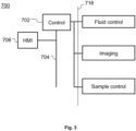
- Fig. 3 shows a rough block diagram of an analysis control system 700.
- HMI human machine interface
- the control box 702 comprises a general purpose programmable logic control (PLC) unit.
- PLC general purpose programmable logic control
- the control box 702 comprises at least one microprocessor for executing control box software comprising program code stored in a memory, dynamic and static memories, I/O modules, A/D and D/A converters and power relays.
- the control box 702 sends electrical power to controllers of fluid line valves and pumps (not shown in Fig.
- control box 702 may also control valves and pumps required when using multiple fluids.
- the control box 702 may measure and relay probe readings from the analysis system to the HMI terminal 706.
- the control box 702 may also control sample handling such as loading and unloading, or optional post-processing analysis of the fluid such as chromatography or mass analysis.
- a dotted line 716 indicates an interface line between the analysis system parts and the control box 702.
- the detecting can be carried out by any suitable technique capable of obtaining information on the deformation or stability of the particle(s), or any part thereof, as it changes or undergoes no change.
- suitable technique capable of obtaining information on the deformation or stability of the particle(s), or any part thereof, as it changes or undergoes no change. Examples include imaging, optical microscopy (producing an image corresponding to the interaction of light with the particle(s)), fluorescence microscopy (producing an image corresponding to or signal proportional to fluorescent absorption or emission of the particle(s)/substance upon suitable excitation), ultraviolet detecting (producing an image and/or a spectra corresponding to or signal proportional to ultraviolet light absorbed and/or emitted by the particle(s)/substance), Raman-spectroscopy (producing a spectra and/or an image based on Raman scattering of the particle(s)), infrared spectroscopy (producing an image and/or a spectra corresponding to or signal proportional to infrared radiation absorbed and/
- the detecting techniques are as such known and can be directed to small volumes as required by the present invention to get information on the properties of at least one individual particle or at least one part thereof.
- Suitable detecting devices are commercially available. What needs to be taken care of is that the vessel wall or window therein is transparent to the radiation used by the detecting system. That is, the vessel itself must not significantly attenuate or alter the radiation to be recorded by the detecting device, for example optical wavelengths in the case of an optical microscopy.
- the detector is calibrated. Calibration may be achieved by producing a calibration curve using compounds of known fluid, such as water, solubility at a constant temperature.
- the calibration involves using crystal density data and/or molecular weight data.
- the detecting may utilize direct illumination, backlight illumination, stroboscopic illumination, fluorescent, phosphorescent, or self-illumination of the sample.
- the images or any other detection data obtained from a detecting device may be stored on an analysis unit, such as a computer, where they are analyzed, using appropriate software and algorithms, in order to determine the physicochemical property, e.g. solubility, as desired.
- the images or any other detection data can also be stored on an external data storage connected to the system.
- the analysis depends on the detecting technique used, since the origin of the recorded radiation is different.
- each of the images obtained comprises a "micrograph", i.e. projection image, of the particle(s) at different stages of e.g. the dissolution process and potentially at different orientations.
- Different orientations of a particle(s) can be imaged e.g. using multiple detecting devices, mirrors, reflectors, using multiple light sources, multiple imaging devices, prisms.
- image processing comprises at least one of:
- computation of the desired physicochemical property or properties is carried out in real time as the detecting proceeds, based on the data obtained until that.
- the result may be an approximate in the beginning and accuracy is improved as more data becomes available.
- the data analysis may also be iterative and a 3D particle(s) reconstruction with topographical and morphological information derived from the image data.
- the computation of the physicochemical property or properties is carried out only after the dissolution process has reached a predefined point, after which the process can be terminated.
- a technical effect is possibility for high-content screening of particle(s) and substances. Another technical effect is determining solubility of very poorly soluble substances. Another technical effect is non-invasive determination of physicochemical properties of matter, such as particles of matter. Another technical effect is possibility to use several fluids per one particle(s) or several particle(s) per one or more fluids.
- acetaminophen Hawkins Inc., MN, USA
- bioactive glass S53P4 BonAlive Biomaterials Ltd, Turku, Finland
- celecoxib Kemprotec, Carnforth, UK
- dicalciumphosphate 2-hydrate Chemische Fabrik Budenheim KG, Budenheim, Germany
- furosemide TI Europe, Zwijndrecht, Belgium
- hydrochlorothiazide Alfa Aesar, Lancashire, UK
- ibuprofen Orion Pharma, Espoo, Finland
- indomethacin Hawkins, MN, USA
- insulin human recombinant SAFC Pharma, MO, USA
- itraconazole Orion Pharma, Espoo, Finland
- ketoprofen Orion Pharma, Espoo, Finland
- naproxen ICN Biomedichals Inc., OH, USA
- phenytoin Orion Pharma, Espoo, Finland
- probenecid Sigma-Al
- Indomethacin is a weak acid organic drug molecule, commonly used as a model compound for poorly soluble drugs.
- the water solubility of indomethacin is commonly presented as "practically insoluble".
- Such qualitative descriptors, while of little value, are often used as quantitation of very small amounts of analyte can be challenging. Further, only less than five percent of specifically trained computational models are able to accurately predict the solubility in simple aqueous buffer of studied compounds indomethacin and probenecid.
- Insulin in 1982, became the first introduced recombinant protein therapeutic.
- Early protein formulation approaches focused on decreasing the solubility of insulin, in order to achieve controlled and sustained release.
- Protein crystal engineering e.g. cocrystallization, is still a widely used strategy in increasing the stability and effectivity of protein therapeutics.
- the rapid screening of physicochemical properties, such as dissolution rate and solubility, during the identification and optimization of such formulations requires reliable high-throughput methods.
- Dicalcium phosphate dihydrate (CaHPO 4 ⁇ 2H 2 O, DCPD, brushite) is a biocompatible material clinically used in orthopedic and dental applications. It has also found applications in e.g. drug delivery, cancer therapy and in the development of biosensors.
- DCPD has a unique advantage over other calcium phosphate cement systems, through its ability to dissolve and be resorbed under physiological conditions. Over time DCPD is converted into the less soluble apatite mineral, depending on the immersion environment.
- the solubility and dissolution rate of such physiologically occurring minerals have a pathological relevance, determining for example the susceptibility to acid attack and remineralization of tooth enamel.
- the supersaturation of these minerals determined by their solubility in various physiological environments, is also the driving force behind the formation of e.g. kidney stones.
- Bioactive glass S53P4 is a FDA approved bone regeneration graft. Its bioactivity depends on the solubility, with the calcium and silicate ions released from the glass being known to promote the bone formation on the cellular level. Using the single crystal method the applicants were able to determine the aqueous solubility and dissolution rate of all model compounds at physiologically relevant conditions.
- the method was extended to determine a complete physicochemical profile (intrinsic solubility, native solubility, equilibrium solubility, dissolution rate, pKa, logP and logO) for the model drug indomethacin.
- a solubility-pH profile was performed in aqueous buffers over the physiologically relevant range of pH 2-9. Additionally the effective solubility was determined in three simulated body fluids (Fasted state simulated intestinal fluid (pH 6.5), fed state simulated intestinal fluid (pH 5) and fasted state simulated gastric fluid (pH 1.6) as well as two commonly used organic solvents (ethanol and octanol).
- the average mass of the individual crystals analyzed was 5.0 ng.
- the substance needed for individual measurements using image based HCA may thus be more than three orders of magnitude less, than what is required in current state of the art miniaturized methods. The gain is much higher when comparing to standard methods, which operate in the mg and g scale.
- the average change in mass between two subsequent detection points was 160 pg with a median of 5.4 pg and a minimum of 4.5 fg.
- the average change in mass from the first data point was on average 5.8 ng with a median of 210 pg and a minimum of 180 fg.
- Ultrapure deionized (MilliQ) water was used to dissolve 12 compounds of known aqueous solubility for producing the standard curve.
- Phosphate buffer solutions pH 2.0, 3.0, 4.5, 5.8, 6.8, 8.0
- buffer solution pH 9.0
- Phosphate-buffered saline solution Sigma-Aldrich, pH 7.4
- FeSSIF fed state simulated intestinal fluid
- FaSSIF fasted state simulated intestinal fluid
- FaSSGF fasted state simulated gastric fluid
- Ethanol Altia, Rajamäki, Finland
- octanol YA Kemia, Helsinki, Finland
- Analysis device was constructed as a flow-through device consisting of two resistant flat metal plates. In the lower thereof a 1mm hole was drilled as an outlet channel. The top metal plate hosted the inlet channel and was prepared with a glass window to facilitate detecting. A 0.2 ⁇ m inorganic membrane filter (Whatman nuclepore) was placed on the bottom plate and the particle(s) to be analyzed placed on top of the portion of the membrane filter being above the outlet channel. The two metal plates were tightly sealed before the start of an experiment. Solvents used as the fluids were degassed and pumped (Agilent 1260 Infinity Quaternary Pump) with a constant flow rate of 1 ml/min through the flow-chamber during all experiments.
- Solvents used as the fluids were degassed and pumped (Agilent 1260 Infinity Quaternary Pump) with a constant flow rate of 1 ml/min through the flow-chamber during all experiments.
- the temperature was adjusted by flowing the liquid through a thermostatted column compartment (Agilent 1200 Series). Particle(s) were imaged through the window with a 8MP CMOS image sensor (Gigastone, CA, USA) on a Leica DMLB microscope mounted with a Leica 50x (N Plan L50X/0.50 - ⁇ /0/C) objective.
- the crystal density for all organic and inorganic compounds were acquired from literature, whereas the crystal density of recombinant human insulin was acquired as the inverse of the partial specific volume of the protein monomer.
- logP partition coefficient
- logO distribution coefficient
- Intrinsic dissolution rate can be determined based on surface area estimation and dissolution rate of the particle(s).
Landscapes
- Health & Medical Sciences (AREA)
- Life Sciences & Earth Sciences (AREA)
- Chemical & Material Sciences (AREA)
- Engineering & Computer Science (AREA)
- Physics & Mathematics (AREA)
- Analytical Chemistry (AREA)
- Pathology (AREA)
- Immunology (AREA)
- General Physics & Mathematics (AREA)
- General Health & Medical Sciences (AREA)
- Biochemistry (AREA)
- Biophysics (AREA)
- Molecular Biology (AREA)
- Food Science & Technology (AREA)
- Medicinal Chemistry (AREA)
- Biomedical Technology (AREA)
- Bioinformatics & Cheminformatics (AREA)
- Pharmacology & Pharmacy (AREA)
- Hematology (AREA)
- Optics & Photonics (AREA)
- Urology & Nephrology (AREA)
- Signal Processing (AREA)
- Dispersion Chemistry (AREA)
- Investigating Or Analysing Materials By Optical Means (AREA)
- Investigating, Analyzing Materials By Fluorescence Or Luminescence (AREA)
Claims (17)
- Verfahren zur Charakterisierung, umfassend:i. Bereitstellen mindestens eines Partikels (130) auf einer Oberfläche (140)ii. Bereitstellen von mindestens einem Fluid (170)iii. Zulassen, dass die Flüssigkeit mit dem Partikel in Kontakt kommt (130)iv. Erkennung des Partikelsv. Analysieren von Daten, die während des Erkennens von Veränderungen des Partikels erfasst wurden; undvi. Korrelieren der Änderungen mit mindestens einer physikalisch-chemischen Eigenschaft des Materials des Partikels (130) oder derjenigen des Fluids; dadurch gekennzeichnet, dass das Partikel (130) auf der Oberfläche (140) festgesetzt ist, und die Oberfläche eine permeable oder semipermeable Schicht ist, auf der das Partikel durch Fluidfluss durch die permeable oder semipermeable Schicht festgesetzt ist.
- Verfahren nach Anspruch 1, wobei das Partikel (130) auf einer permeablen oder semipermeablen Schicht (140) unter Verwendung einer Druckdifferenz des Fluids über der permeablen oder semipermeablen Schicht (140) festgelegt wird.
- Verfahren nach einem der Ansprüche 1-2, wobei Schritt iv. das Erfassen mindestens eines Teils des Partikels (130) umfasst.
- Verfahren nach einem der Ansprüche 1-3, wobei das Partikel (130) eine ursprüngliche Masse von nicht mehr als 100 mg, vorzugsweise nicht mehr als 100 pg, noch bevorzugter nicht mehr als 100 ng aufweist.
- Verfahren nach einem der Ansprüche 1-4 zur Bestimmung von ng-, vorzugsweise pg-, noch bevorzugter fg-, am meisten bevorzugt ag-Änderungen in der Masse des Partikels (130).
- Verfahren nach einem der Ansprüche 1-5, wobei das Partikel (130) auf die Oberfläche (140) unter Verwendung eines Fluids (170) als Träger geladen wird.
- Verfahren nach einem der Ansprüche 1-6, wobei das Partikel (130) beleuchtet wird.
- Verfahren nach einem der Ansprüche 1-7, wobei das Teilchen (130) durch ein Fenster (110) in der Reaktionskammer (20) nachgewiesen wird.
- Verfahren nach einem der Ansprüche 1-8, wobei das Erkennen das Erkennen keiner Änderung zwischen zwei Datenpunkten umfasst.
- Verfahren nach einem der Ansprüche 1-9, wobei das Fluid (170) ein superkritisches Fluid ist.
- Verfahren nach einem der Ansprüche 1-10, wobei die physikalisch-chemische Eigenschaft die Löslichkeit ist.
- System mit einer Analysevorrichtung, die zur Durchführung des Verfahrens nach Anspruch 1 ausgelegt ist und Folgendes umfassteine Reaktionskammer (20);mindestens einen ersten Einlass (120) zum Einleiten eines Fluids (170) in die Reaktionskammer (20);mindestens einen Auslass (160) für den Austritt von Fluid (175) aus der Reaktionskammer (20);eine Immobilisierungszone (140), die auf einer inneren Oberfläche der Reaktionskammer angeordnet ist, wobei die Immobilisierungszone die durchlässige oder eine halbdurchlässige Schicht umfasst, die so ausgelegt ist, dass sie mindestens ein Teilchen über einen Fluidstrom aufnimmt;Mittel, die es ermöglichen, die Immobilisierungszone zu erkennen; und ferner Mittel zur Handhabung des Fluids, um den Durchgang des Fluids durch die Analysevorrichtung zu steuern,Erkennungsmittel undRechenmittel zur Analyse von Daten und zur Bereitstellung von Ergebnissen.
- System nach Anspruch 12, wobei das Mittel zum Erfassen ein Fenster (110) umfasst, das in einer oberen Platte, einer Bodenplatte oder in einer die Reaktionskammer begrenzenden Wand angeordnet ist.
- System nach Anspruch 12 oder 13, bei dem die Mittel zur Erfassung in die Wand (180), die obere Platte (100) oder die Bodenplatte (150) der Vorrichtung integriert sind.
- System nach einem der Ansprüche 12-14, wobei die Immobilisierungszone (140) eine permeable oder semipermeable Schicht umfasst, die so ausgelegt ist, dass sie mindestens ein Partikel über einen Fluidstrom aufnimmt.
- System nach Anspruch 12, wobei es sich bei den Mitteln zur Erkennung um bildgebende Mittel handelt.
- System nach Anspruch 16, das eine Beleuchtungseinrichtung zum Beleuchten der Immobilisierungszone der Reaktionskammer umfasst.
Applications Claiming Priority (2)
| Application Number | Priority Date | Filing Date | Title |
|---|---|---|---|
| FI20165372 | 2016-04-29 | ||
| PCT/FI2017/050328 WO2017187023A1 (en) | 2016-04-29 | 2017-04-28 | Method and device for physicochemical characterization of materials |
Publications (3)
| Publication Number | Publication Date |
|---|---|
| EP3449236A1 EP3449236A1 (de) | 2019-03-06 |
| EP3449236B1 true EP3449236B1 (de) | 2024-03-13 |
| EP3449236C0 EP3449236C0 (de) | 2024-03-13 |
Family
ID=58772583
Family Applications (1)
| Application Number | Title | Priority Date | Filing Date |
|---|---|---|---|
| EP17725649.2A Active EP3449236B1 (de) | 2016-04-29 | 2017-04-28 | Verfahren und vorrichtung zur physiko-chemische materialcharakterisierung |
Country Status (7)
| Country | Link |
|---|---|
| US (2) | US11131658B2 (de) |
| EP (1) | EP3449236B1 (de) |
| JP (1) | JP7096771B2 (de) |
| CN (1) | CN109154548B (de) |
| CA (1) | CA3021753C (de) |
| ES (1) | ES2976359T3 (de) |
| WO (1) | WO2017187023A1 (de) |
Families Citing this family (5)
| Publication number | Priority date | Publication date | Assignee | Title |
|---|---|---|---|---|
| US11131658B2 (en) * | 2016-04-29 | 2021-09-28 | The Solubility Company Oy | Method and device for physicochemical characterization of materials |
| CN113614510A (zh) * | 2019-03-20 | 2021-11-05 | 西铁城时计株式会社 | 被测定物质的检测装置以及被测定物质的检测方法 |
| GB2585076A (en) * | 2019-06-28 | 2020-12-30 | Univ Greenwich | Imaging apparatus |
| WO2025129259A1 (en) * | 2023-12-20 | 2025-06-26 | The University Of Sydney | A particle analyser |
| CN120084774B (zh) * | 2025-05-06 | 2025-09-12 | 中国科学院地质与地球物理研究所 | 原位测定dac中矿物体积和溶解度的方法 |
Citations (1)
| Publication number | Priority date | Publication date | Assignee | Title |
|---|---|---|---|---|
| US20060207356A1 (en) * | 2004-01-30 | 2006-09-21 | Dacheng Tian | Dosage form holder device and methods for immersion testing |
Family Cites Families (34)
| Publication number | Priority date | Publication date | Assignee | Title |
|---|---|---|---|---|
| US4279860A (en) | 1980-06-25 | 1981-07-21 | Smolen Victor F | Multiple injector flow through dissolution cell for dissolution testing apparatus |
| AT399402B (de) | 1992-07-09 | 1995-05-26 | Avl Verbrennungskraft Messtech | Sensormembran eines optischen sensors zur bestimmung eines physikalischen oder chemischen parameters einer probe |
| US5412979A (en) * | 1993-05-03 | 1995-05-09 | Temple University - Of The Commonwealth System Of Higher Education | Method and apparatus for dissolution testing of a dosage form |
| GB9810559D0 (en) * | 1998-05-15 | 1998-07-15 | Bradford Particle Design Ltd | Method and apparatus for particle formation |
| US6929782B1 (en) * | 1999-02-05 | 2005-08-16 | Aventis Pharmaceuticals Inc. | Dissolution test sample holder |
| EP1273901A1 (de) | 2001-07-02 | 2003-01-08 | Université de Liège | Verfahren und Vorrichtung zur automatischen Messung der Grösse und Form von Teilchen |
| CA2480728A1 (en) | 2002-04-01 | 2003-10-16 | Fluidigm Corporation | Microfluidic particle-analysis systems |
| US7923552B2 (en) * | 2004-10-18 | 2011-04-12 | SGF Holdings, LLC | High yield method of producing pure rebaudioside A |
| EP1777510A1 (de) * | 2005-10-21 | 2007-04-25 | Rohm and Haas Company | Verfahren und Vorrichtung zur Prüfung der Auflösung von Produkten |
| US7485854B2 (en) | 2006-05-23 | 2009-02-03 | University Of Helsinki, Department Of Chemistry, Laboratory Of Analytical Chemistry | Sampling device for introduction of samples into analysis system |
| EP1881318A1 (de) | 2006-07-20 | 2008-01-23 | Universiteit Gent | Verfahren und Systeme zur optischen Charakterisierung |
| CN101573618A (zh) * | 2006-09-15 | 2009-11-04 | 赫摩耐提克斯公司 | 通过光学操作与功能化表面有关的颗粒进行表面作图 |
| US20090064768A1 (en) * | 2007-03-13 | 2009-03-12 | Emad Alkhawam | Devices for Determining the Release Profile of Macromolecules and Methods of Using the Same |
| CA2690116A1 (en) | 2007-06-11 | 2008-12-18 | Inhalation Sciences Sweden Ab | A device for studying interaction between particles and lungs |
| CN100483150C (zh) * | 2007-06-18 | 2009-04-29 | 吉林大学 | 流场可视化方法及装置 |
| US20100262381A1 (en) * | 2007-06-29 | 2010-10-14 | Zeng William B | Method of manufacturing and testing solid dosage products and apparatus for the testing |
| US20090078657A1 (en) | 2007-09-26 | 2009-03-26 | Honeywell International Inc. | Device for separation of particulates from a biological sample |
| CN101187657B (zh) * | 2007-11-30 | 2011-04-20 | 中国农业科学院农业资源与农业区划研究所 | 一种测定作物活体生物量变化的方法 |
| CN100533126C (zh) * | 2007-12-21 | 2009-08-26 | 北京工业大学 | 荧光pcr微流控芯片微流体荧光测速控速装置及方法 |
| WO2009088781A1 (en) * | 2008-01-04 | 2009-07-16 | Pion Inc. | Methods and systems for in situ physicochemical property testing |
| US20110081664A1 (en) * | 2008-10-17 | 2011-04-07 | University Of Massachusetts | Multipurpose microfluidic device for mimicking a microenvironment within a tumor |
| EP2211164A1 (de) | 2009-01-27 | 2010-07-28 | Koninklijke Philips Electronics N.V. | Fingerelektroden zur mikrofluidischen Einzelteilchenanalyse |
| TWM388344U (en) * | 2010-03-22 | 2010-09-11 | Teh Seng Pharmaceutical Mfg Co Ltd | Dissolution rate test kit for active components in external medicine patch |
| JP5586098B2 (ja) | 2010-08-04 | 2014-09-10 | ローム アンド ハース カンパニー | 改良された溶出試験装置 |
| EP2458367B1 (de) * | 2010-11-25 | 2015-08-05 | Mettler-Toledo AG | Vorrichtung und Verfahren zur Erkennung fester Substanzen in einer flüssigen Phase |
| CN102507418B (zh) * | 2011-10-26 | 2013-06-05 | 长春迪瑞医疗科技股份有限公司 | 粒子成像室 |
| CA2876358A1 (en) | 2012-06-22 | 2013-12-27 | Malvern Instruments Limited | Particle characterization |
| CN103045466B (zh) * | 2012-12-31 | 2016-01-13 | 山东鑫科生物科技股份有限公司 | 血液微生物培养瓶 |
| FI124792B (fi) | 2013-06-20 | 2015-01-30 | Helsingin Yliopisto | Menetelmä ja laite näytekaasuvirtauksen partikkelien ionisoimiseksi |
| FI127992B (fi) | 2014-08-29 | 2019-07-15 | Svanbaeck Sami | Menetelmä ja järjestelmä aineen liukenemisominaisuuksien määrittämiseksi |
| US10228358B2 (en) * | 2015-04-17 | 2019-03-12 | Pion Inc. | Apparatus and method for the assessment of concentration profiling and permeability rates |
| US11131658B2 (en) * | 2016-04-29 | 2021-09-28 | The Solubility Company Oy | Method and device for physicochemical characterization of materials |
| FI127408B (en) * | 2016-09-29 | 2018-05-15 | Nanoform Finland Oy | Device, method and equipment for solubility testing |
| US11668723B2 (en) * | 2019-07-09 | 2023-06-06 | Logan Instruments Corporation | Automated dissolution/permeation testing system |
-
2017
- 2017-04-28 US US16/096,936 patent/US11131658B2/en active Active
- 2017-04-28 EP EP17725649.2A patent/EP3449236B1/de active Active
- 2017-04-28 WO PCT/FI2017/050328 patent/WO2017187023A1/en not_active Ceased
- 2017-04-28 ES ES17725649T patent/ES2976359T3/es active Active
- 2017-04-28 JP JP2018555575A patent/JP7096771B2/ja active Active
- 2017-04-28 CA CA3021753A patent/CA3021753C/en active Active
- 2017-04-28 CN CN201780026561.0A patent/CN109154548B/zh active Active
-
2021
- 2021-09-14 US US17/474,737 patent/US12146871B2/en active Active
Patent Citations (1)
| Publication number | Priority date | Publication date | Assignee | Title |
|---|---|---|---|---|
| US20060207356A1 (en) * | 2004-01-30 | 2006-09-21 | Dacheng Tian | Dosage form holder device and methods for immersion testing |
Non-Patent Citations (2)
| Title |
|---|
| SAMI SVANB?CK: "Toward accurate high-throughput physicochemical profiling using image-based single-particle analysis", 15 July 2016 (2016-07-15), XP055389650, Retrieved from the Internet <URL:https://helda.helsinki.fi/bitstream/handle/10138/164583/towardac.pdf?sequence=1> [retrieved on 20230331] * |
| ZAFAR U. ET AL: "Drop test: A new method to measure the particle adhesion force", POWDER TECHNOLOGY, vol. 264, 1 September 2014 (2014-09-01), Basel (CH), pages 236 - 241, XP093036471, ISSN: 0032-5910, DOI: 10.1016/j.powtec.2014.04.022 * |
Also Published As
| Publication number | Publication date |
|---|---|
| CN109154548B (zh) | 2022-02-22 |
| US11131658B2 (en) | 2021-09-28 |
| EP3449236A1 (de) | 2019-03-06 |
| CA3021753A1 (en) | 2017-11-02 |
| CA3021753C (en) | 2024-05-21 |
| US12146871B2 (en) | 2024-11-19 |
| US20190094197A1 (en) | 2019-03-28 |
| ES2976359T3 (es) | 2024-07-30 |
| EP3449236C0 (de) | 2024-03-13 |
| US20220003737A1 (en) | 2022-01-06 |
| CN109154548A (zh) | 2019-01-04 |
| JP7096771B2 (ja) | 2022-07-06 |
| JP2019518938A (ja) | 2019-07-04 |
| WO2017187023A1 (en) | 2017-11-02 |
Similar Documents
| Publication | Publication Date | Title |
|---|---|---|
| US12146871B2 (en) | Method and device for physicochemical characterization of materials | |
| Østergaard | UV imaging in pharmaceutical analysis | |
| Lodha et al. | A smart and rapid colorimetric method for the detection of codeine sulphate, using unmodified gold nanoprobe | |
| US10228358B2 (en) | Apparatus and method for the assessment of concentration profiling and permeability rates | |
| Gjelstad et al. | Perspective: Hollow fibre liquid-phase microextraction-principles, performance, applicability, and future directions | |
| US10520411B2 (en) | Method and system for determining dissolution properties of matter | |
| KR20120132668A (ko) | 라만 분석 기반 고속 다중 약물 고속 스크리닝 장치 | |
| US10151675B2 (en) | Method and device for increasing the optical transparency of regions of a tissue sample | |
| JP7068829B2 (ja) | 生物サンプルの生理的性質を測定するための方法および装置 | |
| Solana-Altabella et al. | Computer vision-based analytical chemistry applied to determining iron in commercial pharmaceutical formulations | |
| US8119998B2 (en) | Methods and systems for in situ physicochemical property testing | |
| US20100225898A1 (en) | Optical assembly and method | |
| HUP0900073A2 (en) | Process and equipment for inquiry medical product on dermal surface | |
| CN105675578A (zh) | 一种养殖水中孔雀石绿的快速检测方法 | |
| JP4118281B2 (ja) | マルチチャネル構造に基づく蛍光センサー | |
| JP2009162578A (ja) | 細胞間相互作用を測定するための方法及び装置 | |
| CN110073202B (zh) | 用于在高通量筛选中以高时间分辨率进行测量的方法和系统 | |
| JP2005300528A (ja) | 検体の検査方法に使用する分析要素。 | |
| EP3769082B1 (de) | Verfahren zur bestimmung der konzentration und prozentualen adsorption eines adjuvierten proteins mittels intrinsischer fluoreszenz und system zur durchführung des verfahrens | |
| Fueyo-González et al. | Flour moisture detection with an europium-based luminescent probe | |
| JPS63168543A (ja) | 顕微鏡による螢光偏光測定装置 | |
| Jain et al. | Area under Curve Method Development and Validation of Rizatriptan Benzoate | |
| Fueyo-González et al. | Flour moisture detection with an europium-based luminescent sensor | |
| ES2315054B1 (es) | Celda porta-muestras para analisis de intercambio isotopico h/d e interacciones moleculares para espectroscopia infrarroja de transmision y sus aplicaciones. | |
| Hidi et al. | 1.5. Toward Levofloxacin Monitoring in Human Urine Samples by Employing the LoC-SERS Technique [IH3] |
Legal Events
| Date | Code | Title | Description |
|---|---|---|---|
| STAA | Information on the status of an ep patent application or granted ep patent |
Free format text: STATUS: UNKNOWN |
|
| STAA | Information on the status of an ep patent application or granted ep patent |
Free format text: STATUS: THE INTERNATIONAL PUBLICATION HAS BEEN MADE |
|
| PUAI | Public reference made under article 153(3) epc to a published international application that has entered the european phase |
Free format text: ORIGINAL CODE: 0009012 |
|
| STAA | Information on the status of an ep patent application or granted ep patent |
Free format text: STATUS: REQUEST FOR EXAMINATION WAS MADE |
|
| 17P | Request for examination filed |
Effective date: 20181119 |
|
| AK | Designated contracting states |
Kind code of ref document: A1 Designated state(s): AL AT BE BG CH CY CZ DE DK EE ES FI FR GB GR HR HU IE IS IT LI LT LU LV MC MK MT NL NO PL PT RO RS SE SI SK SM TR |
|
| AX | Request for extension of the european patent |
Extension state: BA ME |
|
| DAV | Request for validation of the european patent (deleted) | ||
| DAX | Request for extension of the european patent (deleted) | ||
| STAA | Information on the status of an ep patent application or granted ep patent |
Free format text: STATUS: EXAMINATION IS IN PROGRESS |
|
| 17Q | First examination report despatched |
Effective date: 20210914 |
|
| RAP1 | Party data changed (applicant data changed or rights of an application transferred) |
Owner name: THE SOLUBILITY COMPANY OY |
|
| GRAP | Despatch of communication of intention to grant a patent |
Free format text: ORIGINAL CODE: EPIDOSNIGR1 |
|
| STAA | Information on the status of an ep patent application or granted ep patent |
Free format text: STATUS: GRANT OF PATENT IS INTENDED |
|
| INTG | Intention to grant announced |
Effective date: 20231004 |
|
| GRAS | Grant fee paid |
Free format text: ORIGINAL CODE: EPIDOSNIGR3 |
|
| GRAA | (expected) grant |
Free format text: ORIGINAL CODE: 0009210 |
|
| STAA | Information on the status of an ep patent application or granted ep patent |
Free format text: STATUS: THE PATENT HAS BEEN GRANTED |
|
| AK | Designated contracting states |
Kind code of ref document: B1 Designated state(s): AL AT BE BG CH CY CZ DE DK EE ES FI FR GB GR HR HU IE IS IT LI LT LU LV MC MK MT NL NO PL PT RO RS SE SI SK SM TR |
|
| REG | Reference to a national code |
Ref country code: GB Ref legal event code: FG4D |
|
| REG | Reference to a national code |
Ref country code: CH Ref legal event code: EP |
|
| REG | Reference to a national code |
Ref country code: DE Ref legal event code: R096 Ref document number: 602017079957 Country of ref document: DE |
|
| REG | Reference to a national code |
Ref country code: IE Ref legal event code: FG4D |
|
| U01 | Request for unitary effect filed |
Effective date: 20240315 |
|
| U07 | Unitary effect registered |
Designated state(s): AT BE BG DE DK EE FI FR IT LT LU LV MT NL PT SE SI Effective date: 20240322 |
|
| U20 | Renewal fee for the european patent with unitary effect paid |
Year of fee payment: 8 Effective date: 20240527 |
|
| PG25 | Lapsed in a contracting state [announced via postgrant information from national office to epo] |
Ref country code: GR Free format text: LAPSE BECAUSE OF FAILURE TO SUBMIT A TRANSLATION OF THE DESCRIPTION OR TO PAY THE FEE WITHIN THE PRESCRIBED TIME-LIMIT Effective date: 20240614 |
|
| PG25 | Lapsed in a contracting state [announced via postgrant information from national office to epo] |
Ref country code: HR Free format text: LAPSE BECAUSE OF FAILURE TO SUBMIT A TRANSLATION OF THE DESCRIPTION OR TO PAY THE FEE WITHIN THE PRESCRIBED TIME-LIMIT Effective date: 20240313 Ref country code: RS Free format text: LAPSE BECAUSE OF FAILURE TO SUBMIT A TRANSLATION OF THE DESCRIPTION OR TO PAY THE FEE WITHIN THE PRESCRIBED TIME-LIMIT Effective date: 20240613 |
|
| REG | Reference to a national code |
Ref country code: ES Ref legal event code: FG2A Ref document number: 2976359 Country of ref document: ES Kind code of ref document: T3 Effective date: 20240730 |
|
| PG25 | Lapsed in a contracting state [announced via postgrant information from national office to epo] |
Ref country code: RS Free format text: LAPSE BECAUSE OF FAILURE TO SUBMIT A TRANSLATION OF THE DESCRIPTION OR TO PAY THE FEE WITHIN THE PRESCRIBED TIME-LIMIT Effective date: 20240613 Ref country code: NO Free format text: LAPSE BECAUSE OF FAILURE TO SUBMIT A TRANSLATION OF THE DESCRIPTION OR TO PAY THE FEE WITHIN THE PRESCRIBED TIME-LIMIT Effective date: 20240613 Ref country code: HR Free format text: LAPSE BECAUSE OF FAILURE TO SUBMIT A TRANSLATION OF THE DESCRIPTION OR TO PAY THE FEE WITHIN THE PRESCRIBED TIME-LIMIT Effective date: 20240313 Ref country code: GR Free format text: LAPSE BECAUSE OF FAILURE TO SUBMIT A TRANSLATION OF THE DESCRIPTION OR TO PAY THE FEE WITHIN THE PRESCRIBED TIME-LIMIT Effective date: 20240614 |
|
| PG25 | Lapsed in a contracting state [announced via postgrant information from national office to epo] |
Ref country code: IS Free format text: LAPSE BECAUSE OF FAILURE TO SUBMIT A TRANSLATION OF THE DESCRIPTION OR TO PAY THE FEE WITHIN THE PRESCRIBED TIME-LIMIT Effective date: 20240713 |
|
| PG25 | Lapsed in a contracting state [announced via postgrant information from national office to epo] |
Ref country code: SM Free format text: LAPSE BECAUSE OF FAILURE TO SUBMIT A TRANSLATION OF THE DESCRIPTION OR TO PAY THE FEE WITHIN THE PRESCRIBED TIME-LIMIT Effective date: 20240313 |
|
| PG25 | Lapsed in a contracting state [announced via postgrant information from national office to epo] |
Ref country code: PL Free format text: LAPSE BECAUSE OF FAILURE TO SUBMIT A TRANSLATION OF THE DESCRIPTION OR TO PAY THE FEE WITHIN THE PRESCRIBED TIME-LIMIT Effective date: 20240313 |
|
| PG25 | Lapsed in a contracting state [announced via postgrant information from national office to epo] |
Ref country code: SK Free format text: LAPSE BECAUSE OF FAILURE TO SUBMIT A TRANSLATION OF THE DESCRIPTION OR TO PAY THE FEE WITHIN THE PRESCRIBED TIME-LIMIT Effective date: 20240313 |
|
| PG25 | Lapsed in a contracting state [announced via postgrant information from national office to epo] |
Ref country code: SM Free format text: LAPSE BECAUSE OF FAILURE TO SUBMIT A TRANSLATION OF THE DESCRIPTION OR TO PAY THE FEE WITHIN THE PRESCRIBED TIME-LIMIT Effective date: 20240313 Ref country code: SK Free format text: LAPSE BECAUSE OF FAILURE TO SUBMIT A TRANSLATION OF THE DESCRIPTION OR TO PAY THE FEE WITHIN THE PRESCRIBED TIME-LIMIT Effective date: 20240313 Ref country code: RO Free format text: LAPSE BECAUSE OF FAILURE TO SUBMIT A TRANSLATION OF THE DESCRIPTION OR TO PAY THE FEE WITHIN THE PRESCRIBED TIME-LIMIT Effective date: 20240313 Ref country code: PL Free format text: LAPSE BECAUSE OF FAILURE TO SUBMIT A TRANSLATION OF THE DESCRIPTION OR TO PAY THE FEE WITHIN THE PRESCRIBED TIME-LIMIT Effective date: 20240313 Ref country code: IS Free format text: LAPSE BECAUSE OF FAILURE TO SUBMIT A TRANSLATION OF THE DESCRIPTION OR TO PAY THE FEE WITHIN THE PRESCRIBED TIME-LIMIT Effective date: 20240713 |
|
| REG | Reference to a national code |
Ref country code: DE Ref legal event code: R097 Ref document number: 602017079957 Country of ref document: DE |
|
| PG25 | Lapsed in a contracting state [announced via postgrant information from national office to epo] |
Ref country code: MC Free format text: LAPSE BECAUSE OF FAILURE TO SUBMIT A TRANSLATION OF THE DESCRIPTION OR TO PAY THE FEE WITHIN THE PRESCRIBED TIME-LIMIT Effective date: 20240313 |
|
| PLBE | No opposition filed within time limit |
Free format text: ORIGINAL CODE: 0009261 |
|
| STAA | Information on the status of an ep patent application or granted ep patent |
Free format text: STATUS: NO OPPOSITION FILED WITHIN TIME LIMIT |
|
| PG25 | Lapsed in a contracting state [announced via postgrant information from national office to epo] |
Ref country code: MC Free format text: LAPSE BECAUSE OF FAILURE TO SUBMIT A TRANSLATION OF THE DESCRIPTION OR TO PAY THE FEE WITHIN THE PRESCRIBED TIME-LIMIT Effective date: 20240313 |
|
| 26N | No opposition filed |
Effective date: 20241216 |
|
| U20 | Renewal fee for the european patent with unitary effect paid |
Year of fee payment: 9 Effective date: 20250425 |
|
| PGFP | Annual fee paid to national office [announced via postgrant information from national office to epo] |
Ref country code: ES Payment date: 20250530 Year of fee payment: 9 Ref country code: GB Payment date: 20250423 Year of fee payment: 9 |
|
| PGFP | Annual fee paid to national office [announced via postgrant information from national office to epo] |
Ref country code: CH Payment date: 20250501 Year of fee payment: 9 |
|
| PGFP | Annual fee paid to national office [announced via postgrant information from national office to epo] |
Ref country code: CZ Payment date: 20250423 Year of fee payment: 9 |
|
| PGFP | Annual fee paid to national office [announced via postgrant information from national office to epo] |
Ref country code: IE Payment date: 20250422 Year of fee payment: 9 |
|
| PG25 | Lapsed in a contracting state [announced via postgrant information from national office to epo] |
Ref country code: CY Free format text: LAPSE BECAUSE OF FAILURE TO SUBMIT A TRANSLATION OF THE DESCRIPTION OR TO PAY THE FEE WITHIN THE PRESCRIBED TIME-LIMIT; INVALID AB INITIO Effective date: 20170428 |
|
| PG25 | Lapsed in a contracting state [announced via postgrant information from national office to epo] |
Ref country code: HU Free format text: LAPSE BECAUSE OF FAILURE TO SUBMIT A TRANSLATION OF THE DESCRIPTION OR TO PAY THE FEE WITHIN THE PRESCRIBED TIME-LIMIT; INVALID AB INITIO Effective date: 20170428 |