EP3449287B1 - Myographisches beobachtungsinstrument - Google Patents
Myographisches beobachtungsinstrument Download PDFInfo
- Publication number
- EP3449287B1 EP3449287B1 EP17722162.9A EP17722162A EP3449287B1 EP 3449287 B1 EP3449287 B1 EP 3449287B1 EP 17722162 A EP17722162 A EP 17722162A EP 3449287 B1 EP3449287 B1 EP 3449287B1
- Authority
- EP
- European Patent Office
- Prior art keywords
- sockets
- detector
- muographic
- shield
- muon
- Prior art date
- Legal status (The legal status is an assumption and is not a legal conclusion. Google has not performed a legal analysis and makes no representation as to the accuracy of the status listed.)
- Active
Links
Images




Classifications
-
- G—PHYSICS
- G01—MEASURING; TESTING
- G01T—MEASUREMENT OF NUCLEAR OR X-RADIATION
- G01T1/00—Measuring X-radiation, gamma radiation, corpuscular radiation, or cosmic radiation
- G01T1/29—Measurement performed on radiation beams, e.g. position or section of the beam; Measurement of spatial distribution of radiation
- G01T1/2914—Measurement of spatial distribution of radiation
- G01T1/2921—Static instruments for imaging the distribution of radioactivity in one or two dimensions; Radio-isotope cameras
- G01T1/2935—Static instruments for imaging the distribution of radioactivity in one or two dimensions; Radio-isotope cameras using ionisation detectors
-
- G—PHYSICS
- G01—MEASURING; TESTING
- G01V—GEOPHYSICS; GRAVITATIONAL MEASUREMENTS; DETECTING MASSES OR OBJECTS; TAGS
- G01V5/00—Prospecting or detecting by the use of ionising radiation, e.g. of natural or induced radioactivity
Definitions
- the invention relates to a muographic observation instrument for the use in a muographic observation system for imaging an internal structure of an object, comprising an arrangement of muon-detecting gaseous detectors arranged to be parallel to a flat surface with certain distance between them.
- a conventional muographic observation instrument took the form of a number of orthogonally arranged muon counters.
- Each muon counter consisted of photomultipliers attached to the longitudinal edge of a square columned scintillator bar, see for example JP 2013-156099 .
- photons are generated inside the scintillator, which are eventually converted to electrons by the photomultipliers and further amplified to an output signal with large amplitude.
- the position of the incident muon can be identified in the muon counter, which is further used to identify the direction of the incident muon as well in the two-scintillator configuration.
- JP 2007271400 discloses a method of acquiring internal structure information of structure using multi-division horizontal muon detecting means, wherein a position sensitive detecting means is provided with first and second forward position sensitive detector complexes, a metal member such as an iron member, and a backward position sensitive detector complex.
- the electromagnetic shower that consists of electrons, positrons and gamma rays from the sky causes simultaneous detection at two points of the muographic observation instrument, and these events generate a fake muon signal as if these occurred along a straight line connecting the two detection points.
- multiple muon detectors are placed in a sequence with a set distance between them, and only the event at which all detectors output signals occurring at the same time and along a straight line is considered to be the detection of a muon; this requires a large-sized, heavy weight device.
- the main purpose of the present invention is to propose a muon detector device which is more effective against noise, has lighter weight, and can be installed easier.
- a muographic observation instrument for the use in a muographic observation system for imaging an internal structure of an object, comprising an arrangement of muon-detecting gaseous detectors arranged to be parallel to a flat surface with certain distance between them; detachable detector sockets mounting the gaseous detectors; radiation shields composed of lead plates arranged in stainless steel cases; detachable shield sockets mounting the radiation shields, said shield sockets are arranged between the detector sockets; and said detector sockets are attached to wires.
- the gaseous detector has 1/10 smaller spatial resolution in comparison to a general scintillator.
- the gaseous detector is lighter than the scintillator detector.
- the muographic observation instrument maintains the same degree of performance as the scintillation detector while also being less heavy and easier to install, which improves the observation conditions.
- the parallel arrangement of the gaseous detectors mounted to the detector sockets allows us to eliminate the noise caused by the electromagnetic shower from the sky.
- the noise caused by the electromagnetic shower from horizontal direction can be removed as well.
- the muon detector is more light weighted and more effective against noise.
- each shield socket mounting a radiation shield is arranged between two adjacent detector sockets mounting the detectors.
- the multiple radiation shields and shield sockets between each detector socket allows for simple installation of the device.
- the detector sockets are connected to lifting handles through wires
- the shield sockets are connected to lifting handles through wires
- the detector sockets and shield sockets are separately liftable by the lifting handles via the wires.
- the gaseous detectors connected to the detector sockets and the radiation shields connected to the shield sockets are easily detachable. This allows for easy and quick installation of the device.
- the radiation shields, the detector sockets and the shield sockets of the instrument are arranged in a disassemblable manner. In this way, even if the access of the installation place is difficult, by decomposing the device it can be easily carried to the installation place. As a result, the installation of the device becomes easy.
- FIG 1 shows the structure of a muographic observation system 20 in which the a muographic observation instrument 30 according to the invention is used.
- the muographic observation system 20 is arranged around gigantic objects such as mountains and by detecting the muons that have passed through the object then processing the detection results with an analyzer 60, an image of the interior of the object is generated.
- the analyzer 60 comprises a software program 62 called "Internal Structure Analyzer ISA" which is a software running on a general-purpose computer.
- the computer has CPU, ROM, RAM, GPU, VRAM, and hard disc drive in the usual way not shown in the Figures, as well as the ISA program 62 installed on the hard disc drive.
- the ISA program 62 has a data-input module 64, an analyzing module 66 which checks the input data for the interior part of the target object, and an output module 68 that provides the results of the analyzing module.
- a monitor 70, a keyboard 72, and a mouse 74 are attached to the computer. Since the ISA program 62 uses basically the same method as described in the literature mentioned in the background part of this document, detailed description of the program is omitted here.
- FIG 2 shows a schematic side view of a preferred construction of the muographic observation instrument 30.
- Figure 3 is a view of the construction shown in Fig.2 from above.
- the muographic observation instrument 30, as shown in Fig.2 has six gaseous detectors 40a-40f and ten radiation shields 50a-50e, 51a-51f as part of a ground unit 32. Since the six gaseous detectors 40a-40f are identical, they are referred and denoted as gaseous detector 40 in the Figure. Also, the ten radiation shields 50, 51, 50a-50e, 51a-51e are identical, so they are referred as radiation shield 50, 51.
- the ground unit 32 has a supporting frame 33, six detector sockets 34a-34f for receiving the six gaseous detectors 40a-40f, five shield sockets 35a-35e for receiving the ten radiation shields 50a-50e, 51a-51f.
- Each detector socket 34a-34f can be raised or lowered by lifting handles 38a-38f, and similarly the shield sockets 35a-35e are also liftable by lifting handles 39a-39e. Lifting of the detector socket 34a and the shield socket 35a is shown by broken lines in the upper left part of Fig. 2 , while the upper right part of Fig. 2 shows the gaseous detector 40e and radiation shields 50e, 51e lifted by the sockets 34e, 35e.
- the supporting frame 33 made of stainless steel includes a lower frame part 33a, an upper frame part 33b, side parts 33c, 33d, and a reinforcement part 33e.
- the six detector sockets 34a-34f are arranged to be parallel to a flat surface with equal intervals, and the five shield sockets 35a-35e are placed between them in a similar arrangement, i.e. in equal intervals.
- the arrangement of the detector sockets 34a-34f and shield sockets 35a-35e are alternatively repeated in the following order: a detector socket 34a, a shield socket 35a, a detector socket 34b, a shield socket 35b, and so on. Therefore, between each of the neighboring gaseous detectors 40 two radiation shields are inserted.
- the lifting handles 38a-38f are connected to the detector sockets 34a-34f through wires 36a-36f. By turning the lifting handles 38a-38f clockwise or anti-clockwise the wires 36a-36f can be wound up or released, and as a result, the detector sockets 34a-34f can be lifted up or down separately.
- the lifting handles 39a-39e are connected to the shield sockets 35a-35e through wires 37a-37e and are used in the same way to lift the shield sockets 35a-35e separately.
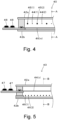
- Figure 4 is a schematic representation of the inside part of the gaseous detector 40 while Figure 5 is a cross sectional view of the plane A-A of Figure 4 .
- Figure 4 is a cross sectional view of the plane B-B of Figure 5 .
- the gaseous detector 40 consists of a known gas-wire chamber, MWPC, Multi Wire Proportional Chamber, two cathode planes 42a, 42b with anode wires 44(1)...44(n) in their middle part arranged parallel to each other at regular intervals with field wires 45(1)...45(n) put between the anode wires.
- a set of signal pick-up wires 46(1)...46(m) are arranged orthogonal to the anode wires 44(1)...44(n), and they are connected to a signal read-out part 48, while the field wires 45(1)...45(n) are connected to a read-out part 47.
- the inner part of the gaseous detector is filled with the mixture of Ar and CO 2 gases which is non-flammable and non-toxic.
- the diameter of the anode wires 44(1)...44(n) is 25 micrometer while the diameter of the field wires 45(1)...45(n) is 100 micrometer, their length is 1500 mm, and the distance between them is 12 mm. Finally, the diameter of the signal pick-up wires is 100 micrometer and their length is 1500 mm. Therefore, the size of the gaseous detector 40 is about 1550 mm x 1550 mm x 25 mm.
- FIG. 6 shows the construction of the radiation shields 50, 51.
- Each radiation shield 50, 51 consists of a bottom frame 52 made of stainless steel, a cover frame 54 made of stainless steel, where the bottom frame 52 has two rectangular flat frames 53a, 53b in which two lead plates 58a, 58b are placed.
- the frames 53a, 53b with a length of 1500 mm and a width of 750 mm made of 10 mm thick stainless steel type SUS304 build up the bottom frame 52 in which the lead plates 58a, 58b with length 1500 mm, width 750 mm, and thickness 50 mm are put, and the cover frame 54 has length 1520 mm and width 1530 mm, and it is also made of 10 mm thick stainless steel type SUS304.
- lead plates are put inside the stainless steel case, and since the lead is soft, it is difficult to maintain its shape under its own weight.
- the six gaseous detectors 40a-40f of the muographic observation instrument 30 are mounted by the six detector sockets 34a-34f and arranged in regular intervals to be parallel to a flat surface. Multiple detectors effectively reduce the possibility of fake track generation due to the accidental coincidence of shower particles in the muographic observation instrument.
- the muon tracks can be identified by connecting the vertex points generated on these gaseous detectors 40 arranged to be parallel to the flat surface. This noise reduction rate is more improved by increasing the number of detectors used for reconstructing the muon tracks because the shower particles hit each gaseous detector 40a-40f randomly and as a result, it is unlikely that those other than muon events will create linear trajectories with more vertex points.
- the muographic observation instrument 30 out of the ten radiation shields 50a-50e, 51a-51e that is mounted to the shield sockets 35a-35e, a pair is placed between each parallel detector socket 34a-34f. Therefore, the noise caused by the electromagnetic shower coming from the horizontal direction is eliminated in this way. Since the muon is strong enough to penetrate many of the radiation shields 50a-50e, 51a-51e this does not affect the detection of the straight track of muons. However, in contrast to muons, the electromagnetic and hadronic particles, mainly electrons, positrons, gamma rays, protons and mesons have a lower power of penetration and therefore, they are terminated or scattered by the radiation shields 50a-50e, 51a-51e.
- Figure 7 shows the scattering of high-energy electrons by the radiation shields 50, 51 as an example.
- one of the main components of the electromagnetic particle is electrons.
- vertex points are identified at all of the 6 gaseous detectors 40a-40f with a slight time difference and along a straight line, these are identified as muon events; the electromagnetic shower is identified if they are not detected along a straight line.
- Figure 8 is a comparison of the muon flux measured by the muographic observation system 20 with the theoretical result as a function of the elevation angle.
- the solid line in the figure shows the theoretically calculated muon flux.
- the thickness of the mountain is thin in the range of high elevations, and becomes thicker as the elevation angle is decreased.
- the maximum thickness of mountain is 2500 m.
- the theoretical muon flux is the 'open-sky' distribution in the negative elevation-angle range, while in the positive elevation-angle range it depends on the thickness of the mountain.
- the muon flux observed by the muographic observation system 20 matches with the 'open-sky' theoretical result, which shows that the noise is removed reasonably.
- the observed flux values are much larger compared to the theoretical result, which indicates the presence of holes in the mountain caused by foaming magma and paths of magma.
- the measured flux is slightly larger than the theoretical expectation, which is thought to be caused by the scattering of muons.
- Plastic scintillator bars are heavier than the gaseous detector 40 for the same active area. Considering a 1500 mm x 1500 mm sensor area, it gives 800 kg for the weight of the plastic scintillator against the 200 kg weight for the gaseous detector. Furthermore, the spatial resolution of the scintillator detector is 100 mm, while it is 10 mm for the gaseous detector. Therefore, in case of the scintillator detector five times thicker lead plates are necessary to exclude the noise caused by the electromagnetic shower from the horizontal direction.
- the ground unit 32 of the above described muographic observation instrument 30 contains six gaseous detectors 40, ten radiation shields 50a-50e, 51a-51e, six detector sockets 34a-34f, and five shield sockets 35a-35e. Because each gaseous detector 40 has 10 times smaller spatial resolution compared to a general scintillator detector, the thickness of the radiation shields 50a-50e, 51a-51e necessary for removing the noise caused by electromagnetic shower mainly charged electrons e-,e+ during the muon detection is 1/5 smaller in the case of the present muographic observation instrument. In addition, the weight of a gaseous detector 40 is 1/4 smaller than a scintillator detector assuming the same sensor area.
- present muographic observation instrument having the same performance as compared to a general detector device using scintillator detector can be made at least five times lighter. Furthermore, due to the structure of the ground unit 32 in the present device containing six gaseous detectors 40a-40f mounted by the detector sockets 34a-34f, the noise caused by the electromagnetic shower from the sky can be efficiently eliminated. In addition, the structure of the ground unit 32 with pairs of the ten radiation shields 50a-50e, 51a-51e mounted by the five shield sockets 35a-35e allows to eliminate also the noise caused by the electromagnetic shower from horizontal direction. Thus, the present muographic observation instrument 30 is lighter, more efficient against noise, and can be installed easier compared to a general scintillator detector.
- the installation of the present device is easy. Furthermore, since the detector sockets 34a-34f and the shield sockets 35a-35e can be lifted up and down individually using the lifting handles 38a-38f, 39a-39e by turning them clockwise or anti-clockwise, the detachment of the gaseous detectors 40a-40f from the detector sockets 34a-34f and the detachment of the radiation shields 50a-50e, 51a-51e from the shield sockets 35a-35e is easy, which makes the installation process of the observation device simple. Besides, concerning the support frame 33 of the ground unit 32, since it can be removed and assembled freely, even when the access of the installation place is difficult, the support frame 33 can be carried there in a disassembled state. As a result, the installation of the device is simple.
- the parallel arrangement is important but the details of the intervals between them are not.
- the number of the gaseous detectors is not limited to six, it can be more as seven or less as five.
- the radiation shield 50, 51 is constituted from two housing frames 53a, 53b in which the lead plates 58a, 58b are put, but it is also possible to use three or more housing frames and lead plates.
- stainless steel cases are housing the lead plates.
- the detector sockets 34a-34f and the shield sockets 35a-35e can be individually lifted, but if not, it does not matter.
- the muographic observation instrument according to the invention can be used in a muographic observation system that can have the inner image of a gigantic object such as a mountain.
Landscapes
- Physics & Mathematics (AREA)
- Life Sciences & Earth Sciences (AREA)
- General Physics & Mathematics (AREA)
- High Energy & Nuclear Physics (AREA)
- Health & Medical Sciences (AREA)
- Molecular Biology (AREA)
- Spectroscopy & Molecular Physics (AREA)
- General Life Sciences & Earth Sciences (AREA)
- Geophysics (AREA)
- Measurement Of Radiation (AREA)
- Analysing Materials By The Use Of Radiation (AREA)
Claims (4)
- Ein myographisches Beobachtungsinstrument (30) zur Verwendung in einem myographischen Beobachtungssystem (20) zur Abbildung einer inneren Struktur eines gigantischen Objekts, wobei das Instrument (30) umfasst:eine Anordnung von Myonen-detektierenden Gasdetektoren (40a-40f), die parallel zu einer flachen Oberfläche mit einem bestimmten Abstand zwischen ihnen angeordnet sind;dadurch gekennzeichnet, dassdas Instrument (30) weiterhin Folgendes umfasst:abnehmbare Detektorsockel (34a-34f), an denen die Gasdetektoren (40a-40f) befestigt sind;Strahlungsschilde (50a-50e, 51a-51e), bestehend aus in Edelstahlgehäusen angeordneten Bleiplatten;abnehmbare Schildfassungen (35a-35e) zur Befestigung der Strahlungsschilde (50a-50e, 51a-51e),die Schildfassungen (35a-35e) sind zwischen den Detektorsockeln (34a-34f) angeordnet;die Detektorsockel (34a-34f) sind an Drähten (36a-36f) befestigt.
- Myographisches Beobachtungsinstrument nach Anspruch 1, wobei jede Schildfassung (35a-35e), in der ein Strahlungsschild (50a-50e, 51a-51e) angebracht ist, zwischen zwei benachbarten Detektorsockeln (34a-34f) angeordnet ist, in dem die Detektoren (40a-40f) angebracht sind.
- Myographisches Beobachtungsinstrument nach Anspruch 1 oder 2, wobei die Detektorsockel (34a-34f) über Drähte (36a-36f) mit Hebegriffen (38a-38f) verbunden sind und die Schildfassungen (35a-35e) über Drähte (37a-37f) mit Hebegriffen (39a-39e) verbunden sind, und die Detektorsockel (34a-34f) und die Schildfassungen (35a-35e) mittels Hebegriffe (38a-38f, 39a-39e) über die Drähte (36a-36f, 37a-37f) separat anhebbar sind.
- Myographisches Beobachtungsinstrument nach einem der Ansprüche 1 bis 3, wobei die Strahlungsschilde (50a-50e, 51a-51e), die Detektorsockel (34a-34f) und die Schildfassungen (35a-35e) in zerlegbarer Weise angeordnet sind.
Applications Claiming Priority (2)
| Application Number | Priority Date | Filing Date | Title |
|---|---|---|---|
| JP2016087436A JP6753594B2 (ja) | 2016-04-25 | 2016-04-25 | ミュオン検出装置 |
| PCT/IB2017/052303 WO2017187308A1 (en) | 2016-04-25 | 2017-04-21 | Muographic observation instrument |
Publications (4)
| Publication Number | Publication Date |
|---|---|
| EP3449287A1 EP3449287A1 (de) | 2019-03-06 |
| EP3449287C0 EP3449287C0 (de) | 2024-03-20 |
| EP3449287B1 true EP3449287B1 (de) | 2024-03-20 |
| EP3449287B8 EP3449287B8 (de) | 2024-06-05 |
Family
ID=58672638
Family Applications (1)
| Application Number | Title | Priority Date | Filing Date |
|---|---|---|---|
| EP17722162.9A Active EP3449287B8 (de) | 2016-04-25 | 2017-04-21 | Myographisches beobachtungsinstrument |
Country Status (7)
| Country | Link |
|---|---|
| US (1) | US10459092B2 (de) |
| EP (1) | EP3449287B8 (de) |
| JP (1) | JP6753594B2 (de) |
| HU (1) | HUE069313T2 (de) |
| MX (1) | MX2018013909A (de) |
| PH (1) | PH12018502189A1 (de) |
| WO (1) | WO2017187308A1 (de) |
Families Citing this family (3)
| Publication number | Priority date | Publication date | Assignee | Title |
|---|---|---|---|---|
| WO2019113604A1 (en) * | 2017-12-08 | 2019-06-13 | Xnihilo Llc | Method and apparatus for processing a particle shower using a laser-driven plasma |
| JP7269595B2 (ja) * | 2018-11-28 | 2023-05-09 | 国立大学法人 東京大学 | 地中状態観測装置 |
| WO2025041694A1 (ja) | 2023-08-18 | 2025-02-27 | 国立大学法人 東京大学 | ミュオンを利用した測位システム |
Family Cites Families (15)
| Publication number | Priority date | Publication date | Assignee | Title |
|---|---|---|---|---|
| JPH08146141A (ja) * | 1994-11-22 | 1996-06-07 | Shimadzu Corp | 電離箱型放射線検出器 |
| JP2007271400A (ja) * | 2006-03-31 | 2007-10-18 | Institute Of Physical & Chemical Research | 多重分割水平ミュオン検出手段を用いて構造物の内部構造情報を得る方法 |
| US7633062B2 (en) * | 2006-10-27 | 2009-12-15 | Los Alamos National Security, Llc | Radiation portal monitor system and method |
| US8143575B2 (en) * | 2007-01-25 | 2012-03-27 | Celight, Inc. | Detection of high Z materials using reference database |
| US7945105B1 (en) * | 2008-04-07 | 2011-05-17 | Decision Sciences International Corporation | Automated target shape detection for vehicle muon tomography |
| JP5463552B2 (ja) * | 2008-10-22 | 2014-04-09 | 国立大学法人 東京大学 | 巨大物体の内部構造解析装置 |
| JP2010175309A (ja) * | 2009-01-28 | 2010-08-12 | Hitachi Ltd | 放射線計測装置 |
| JP5472731B2 (ja) * | 2010-03-02 | 2014-04-16 | 大学共同利用機関法人 高エネルギー加速器研究機構 | 荷電粒子線医療におけるミュオン・モニタリング・システム |
| GB201114699D0 (en) * | 2011-08-25 | 2011-10-12 | Isis Innovation | Apparatus and method for radiation detection |
| JP5963161B2 (ja) | 2012-01-27 | 2016-08-03 | 国立大学法人 東京大学 | 内部状態解析方法およびプログラム並びに内部状態解析システム |
| CA3115225C (en) * | 2013-04-29 | 2022-10-18 | Decision Sciences International Corporation | Muon detector array stations |
| JP6282435B2 (ja) * | 2013-10-04 | 2018-02-21 | 株式会社東芝 | ミュオン軌跡検出器及びミュオン軌跡検出方法 |
| CN106233160B (zh) * | 2014-02-26 | 2019-02-15 | 决策科学国际公司 | 使用宇宙射线电子和μ子的散射和停止辨别低原子重量材料 |
| US9588064B2 (en) * | 2014-10-07 | 2017-03-07 | Decision Sciences International Corporation | Charged particle tomography with improved momentum estimation |
| US10191180B2 (en) * | 2014-12-12 | 2019-01-29 | Lingacom Ltd. | Large scale gas electron multiplier and detection method |
-
2016
- 2016-04-25 JP JP2016087436A patent/JP6753594B2/ja active Active
-
2017
- 2017-04-21 EP EP17722162.9A patent/EP3449287B8/de active Active
- 2017-04-21 MX MX2018013909A patent/MX2018013909A/es unknown
- 2017-04-21 HU HUE17722162A patent/HUE069313T2/hu unknown
- 2017-04-21 WO PCT/IB2017/052303 patent/WO2017187308A1/en not_active Ceased
-
2018
- 2018-10-11 PH PH12018502189A patent/PH12018502189A1/en unknown
- 2018-10-25 US US16/170,659 patent/US10459092B2/en active Active
Also Published As
| Publication number | Publication date |
|---|---|
| US20190064374A1 (en) | 2019-02-28 |
| HUE069313T2 (hu) | 2025-02-28 |
| EP3449287C0 (de) | 2024-03-20 |
| EP3449287A1 (de) | 2019-03-06 |
| JP2017198482A (ja) | 2017-11-02 |
| JP6753594B2 (ja) | 2020-09-09 |
| NZ748669A (en) | 2024-07-05 |
| MX2018013909A (es) | 2022-10-13 |
| EP3449287B8 (de) | 2024-06-05 |
| WO2017187308A1 (en) | 2017-11-02 |
| US10459092B2 (en) | 2019-10-29 |
| PH12018502189A1 (en) | 2019-09-16 |
Similar Documents
| Publication | Publication Date | Title |
|---|---|---|
| US6205195B1 (en) | Coded aperture imaging | |
| US8588370B2 (en) | Article inspection device and inspection method | |
| US8884236B2 (en) | Detector with active collimators | |
| EP2589954B1 (de) | Artikeldetektionsvorrichtung und detektionsverfahren dafür | |
| EP2539902B1 (de) | Systeme und verfahren zur erkennung von materialien mit nuklearer strahlung | |
| US20100019164A1 (en) | Neutron detector | |
| WO1997045755A9 (en) | Coded aperture imaging | |
| US10451745B1 (en) | Muon detectors, systems and methods | |
| JP7769338B2 (ja) | ガンマ線源および中性子源、同時の、検出、識別、定量化および/または位置特定のための装置 | |
| Kawasaki et al. | Detector system of the SENJU single-crystal time-of-flight neutron diffractometer at J-PARC/MLF | |
| Birch et al. | In-beam test of the Boron-10 Multi-Grid neutron detector at the IN6 time-of-flight spectrometer at the ILL | |
| US10459092B2 (en) | Muographic observation instrument | |
| Jo et al. | Design of a muon tomography system with a plastic scintillator and wavelength-shifting fiber arrays | |
| Bhattacharya et al. | VECC-INGA: An exploration of nuclear structure with light ions | |
| Chernyshova et al. | Study of the optimal configuration for a Gas Electron Multiplier aimed at plasma impurity radiation monitoring | |
| Tan et al. | A neutron beam monitor based on ceramic gas electron multiplier with high spatial resolution for low flux measurements | |
| Azimi et al. | Compact Beta-Gamma Radioxenon Detection System with Improved Energy Resolution Using PIPS Detector: SA Azimi et al. | |
| Wang et al. | Achieving sub-pixel position resolution and sub-millimeter depth resolution using a pixelated CdZnTe detector | |
| Badran et al. | A position sensitive β− γ coincidence technique for sample analysis with the upgraded PANDA device | |
| Hasebe et al. | α-particle spectrometer based on xenon gas ionization chamber using coplanar electrodes | |
| Morozov et al. | A 2D gas scintillation detector for thermal neutrons | |
| Vartsky et al. | Detectors for the gamma-ray resonant absorption (GRA) method of explosives detection in cargo: a comparative study | |
| Chen et al. | The performance study of MRPCs used for muon tomography | |
| Sas et al. | High efficiency electron–positron pair spectrometer for the study of light bosons | |
| Barylak et al. | Geant4 simulations of STIX Caliste-SO detector's response to solar X-ray radiation |
Legal Events
| Date | Code | Title | Description |
|---|---|---|---|
| STAA | Information on the status of an ep patent application or granted ep patent |
Free format text: STATUS: UNKNOWN |
|
| STAA | Information on the status of an ep patent application or granted ep patent |
Free format text: STATUS: THE INTERNATIONAL PUBLICATION HAS BEEN MADE |
|
| PUAI | Public reference made under article 153(3) epc to a published international application that has entered the european phase |
Free format text: ORIGINAL CODE: 0009012 |
|
| STAA | Information on the status of an ep patent application or granted ep patent |
Free format text: STATUS: REQUEST FOR EXAMINATION WAS MADE |
|
| 17P | Request for examination filed |
Effective date: 20181123 |
|
| AK | Designated contracting states |
Kind code of ref document: A1 Designated state(s): AL AT BE BG CH CY CZ DE DK EE ES FI FR GB GR HR HU IE IS IT LI LT LU LV MC MK MT NL NO PL PT RO RS SE SI SK SM TR |
|
| AX | Request for extension of the european patent |
Extension state: BA ME |
|
| RIN1 | Information on inventor provided before grant (corrected) |
Inventor name: OLAH, LASZLO Inventor name: KUSAGAYA, TAROU Inventor name: TANAKA, HIROYUKI Inventor name: HAMAR, GERGOE Inventor name: VARGA, DEZSOE |
|
| DAV | Request for validation of the european patent (deleted) | ||
| DAX | Request for extension of the european patent (deleted) | ||
| STAA | Information on the status of an ep patent application or granted ep patent |
Free format text: STATUS: EXAMINATION IS IN PROGRESS |
|
| 17Q | First examination report despatched |
Effective date: 20220105 |
|
| GRAP | Despatch of communication of intention to grant a patent |
Free format text: ORIGINAL CODE: EPIDOSNIGR1 |
|
| STAA | Information on the status of an ep patent application or granted ep patent |
Free format text: STATUS: GRANT OF PATENT IS INTENDED |
|
| INTG | Intention to grant announced |
Effective date: 20231013 |
|
| GRAS | Grant fee paid |
Free format text: ORIGINAL CODE: EPIDOSNIGR3 |
|
| GRAA | (expected) grant |
Free format text: ORIGINAL CODE: 0009210 |
|
| STAA | Information on the status of an ep patent application or granted ep patent |
Free format text: STATUS: THE PATENT HAS BEEN GRANTED |
|
| AK | Designated contracting states |
Kind code of ref document: B1 Designated state(s): AL AT BE BG CH CY CZ DE DK EE ES FI FR GB GR HR HU IE IS IT LI LT LU LV MC MK MT NL NO PL PT RO RS SE SI SK SM TR |
|
| REG | Reference to a national code |
Ref country code: GB Ref legal event code: FG4D |
|
| REG | Reference to a national code |
Ref country code: CH Ref legal event code: EP |
|
| REG | Reference to a national code |
Ref country code: IE Ref legal event code: FG4D |
|
| REG | Reference to a national code |
Ref country code: DE Ref legal event code: R096 Ref document number: 602017080175 Country of ref document: DE |
|
| REG | Reference to a national code |
Ref country code: CH Ref legal event code: PK Free format text: BERICHTIGUNG B8 |
|
| U01 | Request for unitary effect filed |
Effective date: 20240418 |
|
| RAP4 | Party data changed (patent owner data changed or rights of a patent transferred) |
Owner name: UNIVERSITY OF TOKYO Owner name: WIGNER RESEARCH CENTER FOR PHYSICS OF THE HUNGARIAN ACADEMY OF SCIENCE |
|
| PG25 | Lapsed in a contracting state [announced via postgrant information from national office to epo] |
Ref country code: LT Free format text: LAPSE BECAUSE OF FAILURE TO SUBMIT A TRANSLATION OF THE DESCRIPTION OR TO PAY THE FEE WITHIN THE PRESCRIBED TIME-LIMIT Effective date: 20240320 |
|
| REG | Reference to a national code |
Ref country code: LT Ref legal event code: MG9D |
|
| PG25 | Lapsed in a contracting state [announced via postgrant information from national office to epo] |
Ref country code: GR Free format text: LAPSE BECAUSE OF FAILURE TO SUBMIT A TRANSLATION OF THE DESCRIPTION OR TO PAY THE FEE WITHIN THE PRESCRIBED TIME-LIMIT Effective date: 20240621 |
|
| PG25 | Lapsed in a contracting state [announced via postgrant information from national office to epo] |
Ref country code: RS Free format text: LAPSE BECAUSE OF FAILURE TO SUBMIT A TRANSLATION OF THE DESCRIPTION OR TO PAY THE FEE WITHIN THE PRESCRIBED TIME-LIMIT Effective date: 20240620 Ref country code: HR Free format text: LAPSE BECAUSE OF FAILURE TO SUBMIT A TRANSLATION OF THE DESCRIPTION OR TO PAY THE FEE WITHIN THE PRESCRIBED TIME-LIMIT Effective date: 20240320 |
|
| REG | Reference to a national code |
Ref country code: NL Ref legal event code: MP Effective date: 20240320 |
|
| PG25 | Lapsed in a contracting state [announced via postgrant information from national office to epo] |
Ref country code: RS Free format text: LAPSE BECAUSE OF FAILURE TO SUBMIT A TRANSLATION OF THE DESCRIPTION OR TO PAY THE FEE WITHIN THE PRESCRIBED TIME-LIMIT Effective date: 20240620 Ref country code: NO Free format text: LAPSE BECAUSE OF FAILURE TO SUBMIT A TRANSLATION OF THE DESCRIPTION OR TO PAY THE FEE WITHIN THE PRESCRIBED TIME-LIMIT Effective date: 20240620 Ref country code: LT Free format text: LAPSE BECAUSE OF FAILURE TO SUBMIT A TRANSLATION OF THE DESCRIPTION OR TO PAY THE FEE WITHIN THE PRESCRIBED TIME-LIMIT Effective date: 20240320 Ref country code: HR Free format text: LAPSE BECAUSE OF FAILURE TO SUBMIT A TRANSLATION OF THE DESCRIPTION OR TO PAY THE FEE WITHIN THE PRESCRIBED TIME-LIMIT Effective date: 20240320 Ref country code: GR Free format text: LAPSE BECAUSE OF FAILURE TO SUBMIT A TRANSLATION OF THE DESCRIPTION OR TO PAY THE FEE WITHIN THE PRESCRIBED TIME-LIMIT Effective date: 20240621 Ref country code: FI Free format text: LAPSE BECAUSE OF FAILURE TO SUBMIT A TRANSLATION OF THE DESCRIPTION OR TO PAY THE FEE WITHIN THE PRESCRIBED TIME-LIMIT Effective date: 20240320 Ref country code: BG Free format text: LAPSE BECAUSE OF FAILURE TO SUBMIT A TRANSLATION OF THE DESCRIPTION OR TO PAY THE FEE WITHIN THE PRESCRIBED TIME-LIMIT Effective date: 20240320 |
|
| PG25 | Lapsed in a contracting state [announced via postgrant information from national office to epo] |
Ref country code: SE Free format text: LAPSE BECAUSE OF FAILURE TO SUBMIT A TRANSLATION OF THE DESCRIPTION OR TO PAY THE FEE WITHIN THE PRESCRIBED TIME-LIMIT Effective date: 20240320 Ref country code: LV Free format text: LAPSE BECAUSE OF FAILURE TO SUBMIT A TRANSLATION OF THE DESCRIPTION OR TO PAY THE FEE WITHIN THE PRESCRIBED TIME-LIMIT Effective date: 20240320 |
|
| PG25 | Lapsed in a contracting state [announced via postgrant information from national office to epo] |
Ref country code: NL Free format text: LAPSE BECAUSE OF FAILURE TO SUBMIT A TRANSLATION OF THE DESCRIPTION OR TO PAY THE FEE WITHIN THE PRESCRIBED TIME-LIMIT Effective date: 20240320 |
|
| PG25 | Lapsed in a contracting state [announced via postgrant information from national office to epo] |
Ref country code: NL Free format text: LAPSE BECAUSE OF FAILURE TO SUBMIT A TRANSLATION OF THE DESCRIPTION OR TO PAY THE FEE WITHIN THE PRESCRIBED TIME-LIMIT Effective date: 20240320 |
|
| PG25 | Lapsed in a contracting state [announced via postgrant information from national office to epo] |
Ref country code: IS Free format text: LAPSE BECAUSE OF FAILURE TO SUBMIT A TRANSLATION OF THE DESCRIPTION OR TO PAY THE FEE WITHIN THE PRESCRIBED TIME-LIMIT Effective date: 20240720 |
|
| PG25 | Lapsed in a contracting state [announced via postgrant information from national office to epo] |
Ref country code: PT Free format text: LAPSE BECAUSE OF FAILURE TO SUBMIT A TRANSLATION OF THE DESCRIPTION OR TO PAY THE FEE WITHIN THE PRESCRIBED TIME-LIMIT Effective date: 20240722 Ref country code: SM Free format text: LAPSE BECAUSE OF FAILURE TO SUBMIT A TRANSLATION OF THE DESCRIPTION OR TO PAY THE FEE WITHIN THE PRESCRIBED TIME-LIMIT Effective date: 20240320 |
|
| PG25 | Lapsed in a contracting state [announced via postgrant information from national office to epo] |
Ref country code: ES Free format text: LAPSE BECAUSE OF FAILURE TO SUBMIT A TRANSLATION OF THE DESCRIPTION OR TO PAY THE FEE WITHIN THE PRESCRIBED TIME-LIMIT Effective date: 20240320 |
|
| PG25 | Lapsed in a contracting state [announced via postgrant information from national office to epo] |
Ref country code: CZ Free format text: LAPSE BECAUSE OF FAILURE TO SUBMIT A TRANSLATION OF THE DESCRIPTION OR TO PAY THE FEE WITHIN THE PRESCRIBED TIME-LIMIT Effective date: 20240320 Ref country code: EE Free format text: LAPSE BECAUSE OF FAILURE TO SUBMIT A TRANSLATION OF THE DESCRIPTION OR TO PAY THE FEE WITHIN THE PRESCRIBED TIME-LIMIT Effective date: 20240320 |
|
| PG25 | Lapsed in a contracting state [announced via postgrant information from national office to epo] |
Ref country code: PL Free format text: LAPSE BECAUSE OF FAILURE TO SUBMIT A TRANSLATION OF THE DESCRIPTION OR TO PAY THE FEE WITHIN THE PRESCRIBED TIME-LIMIT Effective date: 20240320 |
|
| PG25 | Lapsed in a contracting state [announced via postgrant information from national office to epo] |
Ref country code: SK Free format text: LAPSE BECAUSE OF FAILURE TO SUBMIT A TRANSLATION OF THE DESCRIPTION OR TO PAY THE FEE WITHIN THE PRESCRIBED TIME-LIMIT Effective date: 20240320 |
|
| PG25 | Lapsed in a contracting state [announced via postgrant information from national office to epo] |
Ref country code: SM Free format text: LAPSE BECAUSE OF FAILURE TO SUBMIT A TRANSLATION OF THE DESCRIPTION OR TO PAY THE FEE WITHIN THE PRESCRIBED TIME-LIMIT Effective date: 20240320 Ref country code: SK Free format text: LAPSE BECAUSE OF FAILURE TO SUBMIT A TRANSLATION OF THE DESCRIPTION OR TO PAY THE FEE WITHIN THE PRESCRIBED TIME-LIMIT Effective date: 20240320 Ref country code: RO Free format text: LAPSE BECAUSE OF FAILURE TO SUBMIT A TRANSLATION OF THE DESCRIPTION OR TO PAY THE FEE WITHIN THE PRESCRIBED TIME-LIMIT Effective date: 20240320 Ref country code: PT Free format text: LAPSE BECAUSE OF FAILURE TO SUBMIT A TRANSLATION OF THE DESCRIPTION OR TO PAY THE FEE WITHIN THE PRESCRIBED TIME-LIMIT Effective date: 20240722 Ref country code: PL Free format text: LAPSE BECAUSE OF FAILURE TO SUBMIT A TRANSLATION OF THE DESCRIPTION OR TO PAY THE FEE WITHIN THE PRESCRIBED TIME-LIMIT Effective date: 20240320 Ref country code: IS Free format text: LAPSE BECAUSE OF FAILURE TO SUBMIT A TRANSLATION OF THE DESCRIPTION OR TO PAY THE FEE WITHIN THE PRESCRIBED TIME-LIMIT Effective date: 20240720 Ref country code: ES Free format text: LAPSE BECAUSE OF FAILURE TO SUBMIT A TRANSLATION OF THE DESCRIPTION OR TO PAY THE FEE WITHIN THE PRESCRIBED TIME-LIMIT Effective date: 20240320 Ref country code: EE Free format text: LAPSE BECAUSE OF FAILURE TO SUBMIT A TRANSLATION OF THE DESCRIPTION OR TO PAY THE FEE WITHIN THE PRESCRIBED TIME-LIMIT Effective date: 20240320 Ref country code: CZ Free format text: LAPSE BECAUSE OF FAILURE TO SUBMIT A TRANSLATION OF THE DESCRIPTION OR TO PAY THE FEE WITHIN THE PRESCRIBED TIME-LIMIT Effective date: 20240320 |
|
| REG | Reference to a national code |
Ref country code: CH Ref legal event code: PL |
|
| RAP4 | Party data changed (patent owner data changed or rights of a patent transferred) |
Owner name: UNIVERSITY OF TOKYO Owner name: HUN-REN WIGNER FIZIKAI KUTATOKOEZPONT |
|
| U07 | Unitary effect registered |
Designated state(s): AT BE BG DE DK EE FI FR IT LT LU LV MT NL PT RO SE SI Effective date: 20241112 |
|
| REG | Reference to a national code |
Ref country code: DE Ref legal event code: R097 Ref document number: 602017080175 Country of ref document: DE |
|
| REG | Reference to a national code |
Ref country code: BE Ref legal event code: MM Effective date: 20240430 |
|
| PG25 | Lapsed in a contracting state [announced via postgrant information from national office to epo] |
Ref country code: MC Free format text: LAPSE BECAUSE OF FAILURE TO SUBMIT A TRANSLATION OF THE DESCRIPTION OR TO PAY THE FEE WITHIN THE PRESCRIBED TIME-LIMIT Effective date: 20240320 |
|
| PLBE | No opposition filed within time limit |
Free format text: ORIGINAL CODE: 0009261 |
|
| STAA | Information on the status of an ep patent application or granted ep patent |
Free format text: STATUS: NO OPPOSITION FILED WITHIN TIME LIMIT |
|
| PG25 | Lapsed in a contracting state [announced via postgrant information from national office to epo] |
Ref country code: MC Free format text: LAPSE BECAUSE OF FAILURE TO SUBMIT A TRANSLATION OF THE DESCRIPTION OR TO PAY THE FEE WITHIN THE PRESCRIBED TIME-LIMIT Effective date: 20240320 Ref country code: CH Free format text: LAPSE BECAUSE OF NON-PAYMENT OF DUE FEES Effective date: 20240430 |
|
| 26N | No opposition filed |
Effective date: 20241223 |
|
| GBPC | Gb: european patent ceased through non-payment of renewal fee |
Effective date: 20240620 |
|
| REG | Reference to a national code |
Ref country code: HU Ref legal event code: AG4A Ref document number: E069313 Country of ref document: HU |
|
| PG25 | Lapsed in a contracting state [announced via postgrant information from national office to epo] |
Ref country code: IE Free format text: LAPSE BECAUSE OF NON-PAYMENT OF DUE FEES Effective date: 20240421 |
|
| PG25 | Lapsed in a contracting state [announced via postgrant information from national office to epo] |
Ref country code: GB Free format text: LAPSE BECAUSE OF NON-PAYMENT OF DUE FEES Effective date: 20240620 |
|
| U20 | Renewal fee for the european patent with unitary effect paid |
Year of fee payment: 9 Effective date: 20250429 |
|
| U20 | Renewal fee for the european patent with unitary effect paid |
Year of fee payment: 9 Effective date: 20250429 |
|
| PGFP | Annual fee paid to national office [announced via postgrant information from national office to epo] |
Ref country code: HU Payment date: 20250617 Year of fee payment: 9 |
|
| PG25 | Lapsed in a contracting state [announced via postgrant information from national office to epo] |
Ref country code: CY Free format text: LAPSE BECAUSE OF FAILURE TO SUBMIT A TRANSLATION OF THE DESCRIPTION OR TO PAY THE FEE WITHIN THE PRESCRIBED TIME-LIMIT; INVALID AB INITIO Effective date: 20170421 |