EP3449541B1 - Système de sécurité pour au moins un consommateur d'un véhicule - Google Patents
Système de sécurité pour au moins un consommateur d'un véhicule Download PDFInfo
- Publication number
- EP3449541B1 EP3449541B1 EP17716221.1A EP17716221A EP3449541B1 EP 3449541 B1 EP3449541 B1 EP 3449541B1 EP 17716221 A EP17716221 A EP 17716221A EP 3449541 B1 EP3449541 B1 EP 3449541B1
- Authority
- EP
- European Patent Office
- Prior art keywords
- evaluation
- load
- iln
- ill
- fuse
- Prior art date
- Legal status (The legal status is an assumption and is not a legal conclusion. Google has not performed a legal analysis and makes no representation as to the accuracy of the status listed.)
- Active
Links
Images
Classifications
-
- H—ELECTRICITY
- H02—GENERATION; CONVERSION OR DISTRIBUTION OF ELECTRIC POWER
- H02H—EMERGENCY PROTECTIVE CIRCUIT ARRANGEMENTS
- H02H3/00—Emergency protective circuit arrangements for automatic disconnection directly responsive to an undesired change from normal electric working condition with or without subsequent reconnection ; integrated protection
- H02H3/08—Emergency protective circuit arrangements for automatic disconnection directly responsive to an undesired change from normal electric working condition with or without subsequent reconnection ; integrated protection responsive to excess current
- H02H3/087—Emergency protective circuit arrangements for automatic disconnection directly responsive to an undesired change from normal electric working condition with or without subsequent reconnection ; integrated protection responsive to excess current for DC applications
-
- H—ELECTRICITY
- H02—GENERATION; CONVERSION OR DISTRIBUTION OF ELECTRIC POWER
- H02H—EMERGENCY PROTECTIVE CIRCUIT ARRANGEMENTS
- H02H3/00—Emergency protective circuit arrangements for automatic disconnection directly responsive to an undesired change from normal electric working condition with or without subsequent reconnection ; integrated protection
- H02H3/02—Details
- H02H3/04—Details with warning or supervision in addition to disconnection, e.g. for indicating that protective apparatus has functioned
- H02H3/044—Checking correct functioning of protective arrangements, e.g. by simulating a fault
-
- H—ELECTRICITY
- H02—GENERATION; CONVERSION OR DISTRIBUTION OF ELECTRIC POWER
- H02H—EMERGENCY PROTECTIVE CIRCUIT ARRANGEMENTS
- H02H1/00—Details of emergency protective circuit arrangements
- H02H1/0007—Details of emergency protective circuit arrangements concerning the detecting means
-
- H—ELECTRICITY
- H02—GENERATION; CONVERSION OR DISTRIBUTION OF ELECTRIC POWER
- H02H—EMERGENCY PROTECTIVE CIRCUIT ARRANGEMENTS
- H02H3/00—Emergency protective circuit arrangements for automatic disconnection directly responsive to an undesired change from normal electric working condition with or without subsequent reconnection ; integrated protection
- H02H3/02—Details
- H02H3/05—Details with means for increasing reliability, e.g. redundancy arrangements
-
- H—ELECTRICITY
- H02—GENERATION; CONVERSION OR DISTRIBUTION OF ELECTRIC POWER
- H02H—EMERGENCY PROTECTIVE CIRCUIT ARRANGEMENTS
- H02H3/00—Emergency protective circuit arrangements for automatic disconnection directly responsive to an undesired change from normal electric working condition with or without subsequent reconnection ; integrated protection
- H02H3/08—Emergency protective circuit arrangements for automatic disconnection directly responsive to an undesired change from normal electric working condition with or without subsequent reconnection ; integrated protection responsive to excess current
-
- B—PERFORMING OPERATIONS; TRANSPORTING
- B60—VEHICLES IN GENERAL
- B60R—VEHICLES, VEHICLE FITTINGS, OR VEHICLE PARTS, NOT OTHERWISE PROVIDED FOR
- B60R16/00—Electric or fluid circuits specially adapted for vehicles and not otherwise provided for; Arrangement of elements of electric or fluid circuits specially adapted for vehicles and not otherwise provided for
- B60R16/02—Electric or fluid circuits specially adapted for vehicles and not otherwise provided for; Arrangement of elements of electric or fluid circuits specially adapted for vehicles and not otherwise provided for electric constitutive elements
- B60R16/03—Electric or fluid circuits specially adapted for vehicles and not otherwise provided for; Arrangement of elements of electric or fluid circuits specially adapted for vehicles and not otherwise provided for electric constitutive elements for supply of electrical power to vehicle subsystems or for
Definitions
- the invention is based on a security system for at least one consumer of a vehicle according to the preamble of independent claim 1.
- integrated semiconductor modules for representing an electronic fuse function are known from the prior art. These usually include an electronic circuit breaker for switching a connected electrical load on and off, and also elements for representing protective functions in the event of overcurrent, overtemperature, etc. These known electronic fuses have fixed tripping currents and tripping times. This means that the electronic fuse operates at a fixed operating point and the overcurrent switch-off takes place at a first lower threshold value, which does not damage the semiconductor switch.
- an increased starting current which can be caused, for example, by precharging a capacitor of a connected electrical load impedance or by a breakaway torque of an electric motor, can lead to overcurrent detection and incorrect triggering of the electronic fuse, although the current level has not yet reached a critical threshold at which damage to the semiconductor switches can be expected.
- Such security systems are becoming increasingly “intelligent”, ie equipped with microcontrollers that can adapt to the changing framework conditions, for additional tasks such as current measurement and monitoring, and / or to be able to meet additional physical requirements, such as arcs in systems with a higher supply voltage of more than 24V.
- microcontroller also makes it possible to keep the security area as narrow as possible, ie an overcurrent event is identified very early and switched off.
- the safety system for at least one consumer of a vehicle with the features of independent claim 1 has the advantage that an evaluation and control unit takes over more complex evaluations of the recorded load current, preferably using software modules or program code for the at least one consumer, the execution of which in or multi-digit microsecond range can be done.
- an evaluation and control circuit takes over more complex evaluations of the recorded load current, preferably using software modules or program code for the at least one consumer, the execution of which in or multi-digit microsecond range can be done.
- the evaluation and control circuit reacts considerably faster and is able to make triggering decisions without the involvement of the evaluation and control unit.
- Embodiments of the fuse system according to the invention can quickly switch off the load current in the event of a hard short circuit and still avoid a premature or incorrect switch-off of the load current, in which the load current is switched off, although there is not sufficient overcurrent.
- the evaluation and control circuit monitors the function of the Evaluation and control unit and switches to emergency operation in the event of failure.
- the evaluation and control circuit can advantageously maintain the functionality of the security system even if the evaluation and control unit fails, by using an emergency operation parameter set.
- This limp-home operation differs significantly from normal operation in that not all consumers, supply lines, etc. are now optimally protected, but the relevant consumer is protected, for example, with maximum permissible switch-off threshold values.
- embodiments of the security system according to the invention do not provide redundant protection functions in emergency operation, but provide protection functions with an increased fault tolerance and changed protection objective. This allows embodiments to provide a fault-tolerant security system that includes hardware components and software components.
- Embodiments of the present invention provide a safety system for at least one consumer of a vehicle, which comprises a safety device with at least one electronic fuse for the at least one consumer and an evaluation and control circuit.
- the evaluation and control circuit evaluates the load current through the at least one electronic fuse and compares the load current with at least one predetermined switch-off criterion of a first parameter set.
- the evaluation and control circuit initiates a tripping process which triggers the at least one electronic fuse and switches off the load current to the corresponding consumer when the at least one predefined switch-off criterion is met.
- an evaluation and control unit additionally evaluates the load current through the at least one electronic fuse and compares the load current with at least one predefined complex switch-off criterion of a complex parameter set and interrupts the triggering process initiated by the evaluation and control circuit by outputting at least one corresponding control signal to the evaluations - And control circuit for a predetermined period of time.
- the evaluation and control circuit terminates the triggering process if the load current does not meet the at least one complex switch-off criterion or triggers the at least one electronic fuse and switches off the load current to the corresponding consumer if the load current fulfills the at least one complex switch-off criterion.
- the evaluation and control circuit monitors a functionality of the evaluation and control unit and, if a faulty function of the evaluation and control unit is detected, switches over to an emergency operation mode in which the evaluation and control circuit ignores control signals of the evaluation and control unit and the load current through the evaluates at least one electronic fuse and compares it with at least one specified switch-off criterion of an emergency operation parameter set.
- the evaluation and control circuit triggers the at least one electronic fuse and switches the load current to the corresponding consumer if the at least one specified switch-off criterion of the emergency operation parameter set is met.
- the evaluation and control unit can be understood to mean an electrical device, such as, for example, a control device, in particular an on-board electrical system control device, which processes or evaluates detected sensor and / or measurement signals.
- the evaluation and control unit can have at least one interface, which can be designed in terms of hardware and / or software.
- the interfaces can be part of a so-called system ASIC, for example, which contains a wide variety of functions of the evaluation and control unit.
- the interfaces are separate, integrated circuits or at least partially consist of discrete components.
- the interfaces can be software modules which are present, for example, on a microcontroller in addition to other software modules.
- a computer program product with program code which is stored on a machine-readable medium such as a semiconductor memory, a hard disk memory or an optical memory and is used to carry out the evaluation when the program is executed by the evaluation and control unit.
- the evaluation and control circuit can be designed as an application-specific integrated circuit (ASIC) and / or as a discrete electronic circuit and the evaluation and control unit as a microcontroller.
- ASIC application-specific integrated circuit
- the autonomous hardware components of the fault-tolerant security system can be easily implemented as an ASIC or discrete electronic circuit, and the software component can be implemented by the microcontroller.
- the first parameter set of the evaluation and control circuit can switch off criteria comprise, which implement protection of the load currents of the at least one consumer in a time range of less than or equal to 10 ⁇ s by means of first switch-off thresholds for the load currents.
- the emergency operation parameter set of the evaluation and control circuit can include switch-off criteria, which second switch-off thresholds for the load currents, which can be higher than the first switch-off thresholds, for at least one prioritized consumer and third switch-off thresholds for the load currents, which can be lower than the first switch-off thresholds may affect at least one subordinate consumer.
- the second shutdown thresholds for the load currents can each correspond to a maximum permissible limit value of the associated prioritized consumer and / or the third shutdown thresholds for the load currents can lead to the shutdown of the at least one subordinate consumer.
- the complex parameter set of the evaluation and control unit can include switch-off criteria which, by means of complex evaluation processes, can implement protection of the load currents and / or powers and / or energies of the at least one consumer in a time range of greater than 10 ⁇ s.
- the complex parameter set of the evaluation and control unit can, for example, secure profiles for the at least one consumer, which are based on combinations of load currents and / or powers and / or energies.
- the evaluation and control circuit thus takes over the control and supply tasks as well as the provision of the pre-programmed switch-off thresholds.
- an intelligent fuse system not only protects load currents, but also power and / or energy.
- the evaluation and control unit does all of this, as does the prevention of faulty shutdowns due to increased inrush currents.
- the protection by the evaluation and control circuit takes place parallel to the protection by the evaluation and control unit permanently in the background. While the evaluation and control circuit safeguards less than or equal to 10 ⁇ s on pure current thresholds in the lower time range, the evaluation and control unit secures complex switch-off criteria, such as combinations of load currents, powers, energies or profiles based on them, through complex evaluation processes. However, this is usually done for higher time ranges greater than 10 ⁇ s, preferably greater than 100us. In emergency operation, the protection by the evaluation and control unit is completely eliminated.
- the at least one electronic fuse can work bidirectionally and secure the current path to the corresponding consumer in both current directions.
- the at least one electronic fuse can comprise at least one semiconductor switch, which can supply the associated consumer with a load current in the conductive state and switch off the load current in the blocking state, and can comprise at least one ammeter which measures the load current through the at least one Detect semiconductor switch and output an associated measurement signal to the evaluation and control circuit and the evaluation and control unit, which can represent the detected load current.
- the at least one semiconductor switch can form a measuring shunt for the corresponding ammeter. This advantageously saves layout space and installation space.
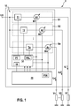
- Fig. 1 shows a schematic block diagram of an embodiment of a security system according to the invention for at least one consumer of a vehicle.
- the illustrated embodiment of a fuse system 1 for at least one consumer V1, V2, Vn of a vehicle comprises a security device 10 which has at least one electronic fuse S1, S2, Sn for the at least one consumer V1, V2, Vn and an evaluation device. and control circuit 12.
- the one evaluation and control circuit 12 evaluates the load current iL1, iL2, iLn through the at least one electronic fuse S1, S2, Sn and compares the load current iL1, iL2, iLn with at least one predetermined switch-off criterion of a first parameter set P1.
- the evaluation and control circuit 12 initiates a tripping process which triggers the at least one electronic fuse S1, S2, Sn and switches off the load current iL1, iL2, iLn to the corresponding consumer V1, V2, Vn when the at least one predefined switch-off criterion has been met .
- an evaluation and control unit 20 additionally evaluates the load current iL1, iL2, iLn through the at least one electronic fuse S1, S2, Sn and compares the load current iL1, iL2, iLn with at least one predefined complex switch-off criterion of a complex parameter set P1K and interrupts it triggering process initiated by the evaluation and control circuit 12 by outputting at least one corresponding control signal to the evaluation and control circuit 12 for a predetermined period of time.
- the evaluation and control circuit 12 terminates the triggering process if the load current iL1, iL2, iLn does not meet the at least one complex switch-off criterion or triggers the at least one electronic fuse S1, S2, Sn and switches the load current iL1, iL2, iLn to the corresponding one Consumers V1, V2, Vn from when the load current iL1, iL2, iLn meets the at least one complex switch-off criterion.
- the evaluation and control circuit 12 monitors a functionality of the evaluation and control unit 20 and, when a faulty function of the evaluation and control unit 20 is detected, switches over to an emergency operation mode in which the evaluation and control circuit 12 controls signals of the evaluation and control unit 20 ignored and evaluates the load current iL1, iL2, iLn through the at least one electronic fuse S1, S2, Sn and compares it with at least one predetermined switch-off criterion of an emergency operation parameter set PNL.
- the evaluation and control circuit 12 triggers the at least one electronic fuse S1, S2, Sn and switches the load current iL1, iL2, iLn to the corresponding consumer V1, V2, Vn if the at least one specified switch-off criterion of the emergency running parameter set PNL is fulfilled.
- the fuse system 1 shown comprises n electronic fuses, of which three electronic fuses S1, S2, Sn are shown as examples, for n consumers, of which three consumers V1, V2, Vn are shown as examples.
- the electronic fuses S1, S2, Sn each comprise at least one semiconductor switch T1, T2, Tn, which supplies the associated consumer V1, V2, Vn with a load current iL1, iL2, iLn in the conductive state and the load current iL1, iL2 in the blocking state.
- iLn switches off, and at least one ammeter A1, A2, An, which detects the load current iL1, iL2, iLn through the at least one semiconductor switch T1, T2, Tn and an associated measurement signal M1, M2, Mn to the evaluation and control circuit 12 and the Outputs evaluation and control unit 20, which represents the detected load current iL1, iL2, iLn.
- the electronic fuses S1, S2, Sn operate bidirectionally and secure the current path to the corresponding consumer V1, V2, Vn in both current directions.
- the semiconductor switches T1, T2, Tn of the electronic fuses S1, S2, Sn can each form a measuring shunt for the corresponding ammeter A1, A2, An.
- a monitoring function 14, which monitors the functionality of the evaluation and control unit 20, can be implemented in the evaluation and control circuit 12, for example, in the manner of a “watchdog function” known from the prior art.
- the evaluation and control circuit 12 is designed as an application-specific integrated circuit ASIC, which has a memory in which the first parameter set P1 and the emergency running parameter set PNL are stored.
- the evaluation and control circuit 12 can also be designed as a discrete electronic circuit.
- the evaluation and control unit 20 is designed as a microcontroller in which the complex parameter set P1K is stored.
- the evaluation and control unit 20 designed as a microcontroller processes program code from software modules in order to carry out complex evaluations of the detected load currents iL1, iL2, iLn.
- the first parameter set P1 of the evaluation and control circuit 12 comprises switch-off criteria which, by means of first switch-off thresholds for the load currents iL1, iL2, iLn, safeguard the load currents iL1, iL2, iLn of the at least one consumer V1, V2, Vn in a time range of less than or equal to 10 ⁇ s implement.
- the emergency operation parameter set PNL of the evaluation and control circuit 12 comprises switch-off criteria, which second switch-off thresholds for the load currents iL1, iL2, iLn, which are higher than the first switch-off thresholds, for at least one prioritized consumer V1, V2, Vn and third switch-off thresholds for the load currents iL1, iL2, iLn, which are lower than the first switch-off thresholds, relate to at least one subordinate consumer V1, V2, Vn.
- the second shutdown thresholds for the load currents iL1, iL2, iLn each correspond to a maximum permissible limit value of the associated prioritized consumer V1, V2, Vn and / or the third shutdown thresholds for the load currents iL1, iL2, iLn lead to the shutdown of the at least one subordinate one Lead consumer V1, V2, Vn.
- a first consumer V1 and a second consumer are prioritized consumers, which are very important for the vehicle function
- an nth consumer Vn is a subordinate consumer, which is not required for the function of the vehicle
- a lower third switch-off threshold is stored in the emergency operation parameter set PNL than the first switch-off threshold in the first parameter set P1.
- the low third shutdown threshold leads to the direct shutdown of the nth consumer Vn.
- the complex parameter set P1K of the evaluation and control unit 20 includes switch-off criteria which, by means of complex evaluation processes, secure the load currents iL1, iL2, iLn and / or the powers and / or energies of the at least one consumer V1, V2, Vn in a time range of greater than 10 ⁇ s implement.
- the complex parameter set P1K of the evaluation and control unit 20 secures profiles for the at least one consumer V1, V2, Vn, which are based on combinations of load currents iL1, iL2, iLn and / or powers and / or energies.
- the hardware of the security system is based on the evaluation and control circuit designed as an ASIC, power electronics in the form of the semiconductor switches and the evaluation and control unit designed as a microcontroller.
- the evaluation and control circuit which is designed as an ASIC, has an analog measuring device which monitors predetermined current threshold values independently of the evaluation and control unit which is designed as a microcontroller. If these current threshold values are exceeded by an overcurrent, the evaluation and control circuit implemented as ASIC initiates the tripping or switch-off process.
- the evaluation and control unit designed as a microcontroller can, however, prevent this switch-off process by rapid intervention for a predetermined period of time.
- the evaluation and control circuit designed as ASIC monitors the evaluation and control unit designed as a microcontroller.
- the evaluation and control unit designed as a microcontroller can prevent the shutdown. However, if the evaluation and control unit designed as a microcontroller failed, the overcurrent would provoke the shutdown. However, if the evaluation and control circuit designed as ASIC has recognized the failure of the evaluation and control unit designed as microcontroller, the evaluation and control circuit designed as ASIC can autonomously access a second set of emergency operation parameters that is specified in advance. In contrast to the first parameter set, this second emergency running parameter set does not have the optimal protection as the first goal but the maximum functional reliability. This can mean that subordinate consumers are switched off immediately in order to be able to provide important consumers with increased energy reserves. In the example above, e.g. the switch-off threshold can be raised to the maximum permissible limit in order to prevent the switch-off by the overcurrent.
Landscapes
- Emergency Protection Circuit Devices (AREA)
- Financial Or Insurance-Related Operations Such As Payment And Settlement (AREA)
- Engineering & Computer Science (AREA)
- Artificial Intelligence (AREA)
- Evolutionary Computation (AREA)
Claims (10)
- Système de protection (1) pour au moins un consommateur électrique (V1, V2, Vn) d'un véhicule, avec un dispositif de protection (10) comprenant au moins un fusible électronique (S1, S2, Sn) pour ledit au moins un consommateur électrique (V1, V2, Vn) et un circuit d'évaluation et de commande (12) qui évalue le courant de charge (iL1, iL2, iLn) à travers ledit au moins un fusible électronique (S1, S2, Sn) et le compare à au moins un critère de coupure prédéfini d'un premier ensemble de paramètres (P1), dans lequel le circuit d'évaluation et de commande (12) lance un processus de déclenchement qui déclenche ledit au moins un fusible électronique (S1, S2, Sn) et coupe le courant de charge (iL1, iL2, iLn) pour le consommateur électrique correspondant (V1, V2, Vn) si ledit au moins un critère de coupure prédéfini est rempli, caractérisé en ce qu'une unité d'évaluation et de commande (20) évalue également le courant de charge (iL1, iL2, iLn) à travers ledit au moins un fusible électronique (S1, S2, Sn) et le compare à au moins un critère de coupure complexe prédéfini d'un ensemble de paramètres complexes (P1K) et interrompt pendant une durée prédéterminée le processus de déclenchement lancé par le circuit d'évaluation et de commande (12) en sortant au moins un signal de commande correspondant à destination du circuit d'évaluation et de commande (12), dans lequel le circuit d'évaluation et de commande (12) abandonne le processus de déclenchement si le courant de charge (iL1, iL2, iLn) ne remplit pas ledit au moins un critère de coupure complexe ou déclenche ledit au moins un fusible électronique (S1, S2, Sn) et coupe le courant de charge (iL1, iL2, iLn) pour le consommateur électrique correspondant (V1, V2, Vn) si le courant de charge (iL1, iL2, iLn) remplit ledit au moins un critère de coupure complexe, dans lequel le circuit d'évaluation et de commande (12) surveille une fonctionnalité de l'unité d'évaluation et de commande (20) et commute en cas de fonctionnement erroné reconnu de l'unité d'évaluation et de commande (20) sur un fonctionnement de secours dans lequel le circuit d'évaluation et de commande (12) ignore les signaux de commande de l'unité d'évaluation et de commande (20) et évalue le courant de charge (iL1, iL2, iLn) à travers ledit au moins un fusible électronique (S1, S2, Sn) et le compare à au moins un critère de coupure prédéfini d'un ensemble de paramètres de fonctionnement de secours (PNL), dans lequel le circuit d'évaluation et de commande (12) déclenche ledit au moins un fusible électronique (S1, S2, Sn) et coupe le courant de charge (iL1, iL2, iLn) pour le consommateur électrique correspondant (V1, V2, Vn) si ledit au moins un critère de coupure prédéfini de l'ensemble de paramètres de fonctionnement de secours (PNL) est rempli.
- Système de protection selon la revendication 1, caractérisé en ce que le circuit d'évaluation et de commande (12) est réalisé sous la forme d'un circuit intégré spécifique à une application (ASIC) et/ou d'un circuit électronique discret et l'unité d'évaluation et de commande (20) est réalisée sous la forme d'un microcontrôleur.
- Système de protection selon la revendication 1 ou 2, caractérisé en ce que est réalisé le premier ensemble de paramètres (P1) du circuit d'évaluation et de commande (12) comprend des critères de coupure qui mettent en œuvre par des premiers seuils de coupure pour les courants de charge (iL1, iL2, iLn) une protection des courants de charge (iL1, iL2, iLn) du au moins un consommateur électrique (V1, V2, Vn) dans une plage de temps inférieure ou égale à 10 µs.
- Système de protection selon la revendication 3, caractérisé en ce que l'ensemble de paramètres de fonctionnement de secours (PNL) du circuit d'évaluation et de commande (12) comprend des critères de coupure concernant des deuxièmes seuils de coupure pour les courants de charge (iL1, iL2, iLn) qui sont supérieurs aux premiers seuils de coupure pour au moins un consommateur électrique prioritaire (V1, V2, Vn) et des troisièmes seuils de coupure pour les courants de charge (iL1, iL2, iLn) qui sont inférieurs aux premiers seuils de coupure pour au moins un consommateur électrique de priorité inférieure (V1, V2, Vn).
- Système de protection selon la revendication 4, caractérisé en ce que les deuxièmes seuils de coupure pour les courants de charge (iL1, iL2, iLn) correspondent respectivement à une valeur limite admissible maximale du consommateur électrique prioritaire associé (V1, V2, Vn) et/ou les troisièmes seuils de coupure pour les courants de charge (iL1, iL2, iLn) entraînent la coupure du au moins un consommateur électrique de priorité inférieure (V1, V2, Vn) .
- Système de protection selon l'une quelconque des revendications 1 à 5, caractérisé en ce que l'ensemble de paramètres complexes (P1K) de l'unité d'évaluation et de commande (20) comprend des critères de coupure mettant en œuvre par des opérations d'évaluation complexes une protection des courants de charge (iL1, iL2, iLn) et/ou des puissances et/ou des énergies du au moins un consommateur électrique (V1, V2, Vn) dans une plage de temps supérieure à 10 ps.
- Système de protection selon la revendication 6, caractérisé en ce que l'ensemble de paramètres complexes (P1K) de l'unité d'évaluation et de commande (20) protège pour ledit au moins un consommateur électrique (V1, V2, Vn) des profils qui sont basés sur des combinaisons de courants de charge (iL1, iL2, iLn) et/ou de puissances et/ou d'énergies.
- Système de protection selon l'une quelconque des revendications 1 à 7, caractérisé en ce que ledit au moins un fusible électronique (S1, S2, Sn) fonctionne de manière bidirectionnelle et protège le trajet de courant jusqu'au consommateur électrique correspondant (V1, V2, Vn) dans les deux sens du courant.
- Système de protection selon l'une quelconque des revendications 1 à 8, caractérisé en ce que ledit au moins un fusible électronique (S1, S2, Sn) comprend au moins un commutateur statique (T1, T2, Tn), qui alimente le consommateur électrique associé (V1, V2, Vn) en courant de charge (iL1, iL2, iLn) à l'état conducteur et coupe le courant de charge (iL1, iL2, iLn) à l'état bloqué, et au moins un ampèremètre (A1, A2, An) qui détecte le courant de charge (iL1, iL2, iLn) à travers ledit au moins un commutateur statique (T1, T2, Tn) et émet un signal de mesure associé (M1, M2, Mn) à destination du circuit d'évaluation et de commande (12) et de l'unité d'évaluation et de commande (20) qui représente le courant de charge détecté (iL1, iL2, iLn).
- Système de protection selon la revendication 9, caractérisé en ce que ledit au moins un commutateur statique (T1, T2, Tn) réalise un shunt de mesure pour l'ampèremètre correspondant (A1, A2, An).
Applications Claiming Priority (2)
| Application Number | Priority Date | Filing Date | Title |
|---|---|---|---|
| DE102016207020.7A DE102016207020A1 (de) | 2016-04-26 | 2016-04-26 | Sicherungssystem für mindestens einen Verbraucher eines Fahrzeugs |
| PCT/EP2017/058413 WO2017186475A1 (fr) | 2016-04-26 | 2017-04-07 | Système de sécurité pour au moins un consommateur d'un véhicule |
Publications (2)
| Publication Number | Publication Date |
|---|---|
| EP3449541A1 EP3449541A1 (fr) | 2019-03-06 |
| EP3449541B1 true EP3449541B1 (fr) | 2020-06-10 |
Family
ID=58503626
Family Applications (1)
| Application Number | Title | Priority Date | Filing Date |
|---|---|---|---|
| EP17716221.1A Active EP3449541B1 (fr) | 2016-04-26 | 2017-04-07 | Système de sécurité pour au moins un consommateur d'un véhicule |
Country Status (6)
| Country | Link |
|---|---|
| US (1) | US10923902B2 (fr) |
| EP (1) | EP3449541B1 (fr) |
| JP (1) | JP6629463B2 (fr) |
| CN (1) | CN109075553B (fr) |
| DE (1) | DE102016207020A1 (fr) |
| WO (1) | WO2017186475A1 (fr) |
Families Citing this family (11)
| Publication number | Priority date | Publication date | Assignee | Title |
|---|---|---|---|---|
| DE102016210058A1 (de) * | 2016-06-08 | 2017-12-14 | Robert Bosch Gmbh | Stromverteiler und Sicherungssystem für ein Fahrzeug |
| DE102019120567A1 (de) * | 2019-07-30 | 2021-02-04 | Bayerische Motoren Werke Aktiengesellschaft | Fahrzeug-Bordnetz und Verfahren zum Schutz eines Fahrzeug-Bordnetzes |
| US11646566B2 (en) | 2020-12-16 | 2023-05-09 | Lear Corporation | Apparatus for permanent supply with a switch |
| EP4063888B1 (fr) * | 2021-03-25 | 2023-07-26 | Future Systems Besitz GmbH | Procédé et appareil de détection de défaillance de fusible |
| DE102021113107A1 (de) * | 2021-05-20 | 2022-11-24 | Lisa Dräxlmaier GmbH | Elektronischer Sicherungsschaltkreis |
| US12088183B2 (en) | 2021-10-19 | 2024-09-10 | Lear Corporation | Electrical system |
| US11811212B2 (en) * | 2022-03-04 | 2023-11-07 | GM Global Technology Operations LLC | Synchronization of electronic fuses in vehicle power distribution |
| CN114552524B (zh) * | 2022-03-09 | 2023-08-22 | 中铁十五局集团有限公司 | 一种车载复合电源用高压配电单元及其控制方法 |
| CN116027103B (zh) * | 2023-03-29 | 2023-09-15 | 荣耀终端有限公司 | 功耗检测电路、功耗检测芯片及终端设备 |
| DE102024203476A1 (de) * | 2024-04-15 | 2025-10-16 | Conti Temic Microelectronic Gmbh | Schaltungsanordnung zur Steuerung einer elektronischen Sicherung und Verfahren zum Betreiben einer solchen Schaltungsanordnung |
| CN119502704B (zh) * | 2024-11-14 | 2025-09-26 | 一汽解放汽车有限公司 | 新能源汽车高压系统及具其的车辆 |
Family Cites Families (16)
| Publication number | Priority date | Publication date | Assignee | Title |
|---|---|---|---|---|
| JP4419270B2 (ja) * | 2000-04-20 | 2010-02-24 | 株式会社デンソー | 電気負荷駆動用ic |
| JP2001309546A (ja) * | 2000-04-27 | 2001-11-02 | Mitsubishi Cable Ind Ltd | 車両用配線系統の保護装置 |
| JP4171449B2 (ja) * | 2004-06-30 | 2008-10-22 | 三洋電機株式会社 | 車両用の電源装置 |
| US8570699B2 (en) * | 2005-04-22 | 2013-10-29 | Lear Corporation | Relayless and fuseless junction box |
| DE102008012605B4 (de) | 2008-03-05 | 2013-01-31 | Siemens Aktiengesellschaft | Schutzschaltgerät zum Überwachen des elektrischen Stromflusses zu einem elektrischen Verbrauch |
| JP5489742B2 (ja) * | 2010-01-22 | 2014-05-14 | 三菱電機株式会社 | 保護継電器 |
| JP5494255B2 (ja) * | 2010-06-07 | 2014-05-14 | 富士電機株式会社 | 安全制御システム |
| US8553376B2 (en) * | 2010-12-11 | 2013-10-08 | The Boeing Company | Synchronous rectified PWM regulator with auto fault clearing |
| FR2968855B1 (fr) * | 2010-12-14 | 2012-12-07 | Schneider Electric Ind Sas | Procede et dispositif de surveillance d'un dispositif equipe d'un microprocesseur |
| US20120226453A1 (en) | 2011-03-02 | 2012-09-06 | General Electric Company | Circuit breaker trip unit |
| US9214797B2 (en) | 2013-02-13 | 2015-12-15 | General Electric Company | Apparatus, systems, and methods for operation of a trip unit in a circuit protection device |
| JP6052114B2 (ja) * | 2013-09-11 | 2016-12-27 | 株式会社デンソー | 駆動力制御装置 |
| US10391957B2 (en) * | 2016-04-05 | 2019-08-27 | Ford Global Technologies, Llc | Integrated power distribution system for a vehicle |
| DE102016210058A1 (de) * | 2016-06-08 | 2017-12-14 | Robert Bosch Gmbh | Stromverteiler und Sicherungssystem für ein Fahrzeug |
| CN106849001A (zh) * | 2017-04-18 | 2017-06-13 | 安徽中电电气有限公司 | 光伏汇流箱专用连续可调电子熔断器 |
| US11070049B2 (en) * | 2017-11-08 | 2021-07-20 | Eaton Intelligent Power Limited | System, method, and apparatus for power distribution in an electric mobile application using a combined breaker and relay |
-
2016
- 2016-04-26 DE DE102016207020.7A patent/DE102016207020A1/de not_active Withdrawn
-
2017
- 2017-04-07 US US16/096,121 patent/US10923902B2/en not_active Expired - Fee Related
- 2017-04-07 JP JP2018555920A patent/JP6629463B2/ja not_active Expired - Fee Related
- 2017-04-07 WO PCT/EP2017/058413 patent/WO2017186475A1/fr not_active Ceased
- 2017-04-07 EP EP17716221.1A patent/EP3449541B1/fr active Active
- 2017-04-07 CN CN201780026175.1A patent/CN109075553B/zh active Active
Non-Patent Citations (1)
| Title |
|---|
| None * |
Also Published As
| Publication number | Publication date |
|---|---|
| DE102016207020A1 (de) | 2017-10-26 |
| CN109075553B (zh) | 2019-09-10 |
| US10923902B2 (en) | 2021-02-16 |
| JP6629463B2 (ja) | 2020-01-15 |
| EP3449541A1 (fr) | 2019-03-06 |
| WO2017186475A1 (fr) | 2017-11-02 |
| CN109075553A (zh) | 2018-12-21 |
| JP2019515619A (ja) | 2019-06-06 |
| US20190140438A1 (en) | 2019-05-09 |
Similar Documents
| Publication | Publication Date | Title |
|---|---|---|
| EP3449541B1 (fr) | Système de sécurité pour au moins un consommateur d'un véhicule | |
| EP3469620B1 (fr) | Répartiteur de courant et système de sécurité pour un véhicule | |
| DE102014214840B4 (de) | Vorrichtung zur Überwachung eines Hochvolt-Bordnetzes eines elektrisch betriebenen Fahrzeugs auf das Vorliegen einer Überlastung | |
| DE102015107718B4 (de) | Vorrichtung und Verfahren zum Absichern einer Bordnetz-Komponente eines Fahrzeug-Bordnetzes | |
| EP4084249B1 (fr) | Réseau embarqué; en particulier pour un véhicule automobile | |
| EP2104974B1 (fr) | Dispositif de protection contre les surtensions pour un appareil électronique | |
| EP2182605B1 (fr) | Agencement de commutation pour la protection de dispositifs électroniques contre des tensions logiques erronées | |
| EP3539192A1 (fr) | Répartiteur de puissance et réseau de bord comprenant au moins un répartiteur de puissance | |
| DE102015014798A1 (de) | Motorantrieb mit Funktion zur Verhinderung von Folgeschäden | |
| EP3452336B1 (fr) | Dispositif de commande multi-tension pour véhicule automobile, véhicule automobile et procédé de fonctionnement du dispositif de commande | |
| DE102016121447B4 (de) | Vorrichtung und Verfahren zum Absichern einer Bordnetzkomponente eines Fahrzeug-Bordnetzes | |
| DE102018118647A1 (de) | Einzelfehlersichere elektronische Sicherheitsschaltung | |
| EP3036832B1 (fr) | Procédé de protection d'un commutateur à semi-conducteur commandable contre les surcharges et les courts-circuits dans un circuit de charge | |
| EP1088318A2 (fr) | Dispositif de deconnexion fiable d'une charge electrique, notamment a forte inductivite, d'un systeme d'alimentation en tension continue electrique | |
| WO2002071600A2 (fr) | Dispositif de commutation de securite | |
| DE112016005736B4 (de) | Fahrzeugsteuervorrichtung | |
| EP2672595B1 (fr) | Agencement de circuit et procédé destinés à la coupure du courant continu | |
| DE102016123860A1 (de) | Schutzanordnung von elektrischen Verbrauchern und deren Anschlussleitungen vor Überstrom | |
| WO2018104486A1 (fr) | Système de protection de consommateurs électriques et de leurs lignes contre les surintensités | |
| DE202017006695U1 (de) | Elektronische Leitungsschutzschaltung sowie Leitungsschutzsystem | |
| DE102019204429A1 (de) | Schutzvorrichtung für eine Treiberschaltung und Verfahren zum Schutz einer Treiberschaltung | |
| EP4435988A2 (fr) | Dispositif de protection contre les surtensions pour un appareil électrique | |
| EP4620742A1 (fr) | Dispositif de distribution de courant électronique et procédé de fonctionnement d'un tel dispositif de distribution de courant | |
| DE102024205644A1 (de) | Verfahren zum Betreiben eines Bordnetzes | |
| WO2024088650A1 (fr) | Procédé et dispositif de protection pour la protection d'un dispositif contre un courant de défaut et véhicule automobile configuré de manière correspondante |
Legal Events
| Date | Code | Title | Description |
|---|---|---|---|
| STAA | Information on the status of an ep patent application or granted ep patent |
Free format text: STATUS: UNKNOWN |
|
| STAA | Information on the status of an ep patent application or granted ep patent |
Free format text: STATUS: THE INTERNATIONAL PUBLICATION HAS BEEN MADE |
|
| PUAI | Public reference made under article 153(3) epc to a published international application that has entered the european phase |
Free format text: ORIGINAL CODE: 0009012 |
|
| STAA | Information on the status of an ep patent application or granted ep patent |
Free format text: STATUS: REQUEST FOR EXAMINATION WAS MADE |
|
| 17P | Request for examination filed |
Effective date: 20181126 |
|
| AK | Designated contracting states |
Kind code of ref document: A1 Designated state(s): AL AT BE BG CH CY CZ DE DK EE ES FI FR GB GR HR HU IE IS IT LI LT LU LV MC MK MT NL NO PL PT RO RS SE SI SK SM TR |
|
| AX | Request for extension of the european patent |
Extension state: BA ME |
|
| DAV | Request for validation of the european patent (deleted) | ||
| DAX | Request for extension of the european patent (deleted) | ||
| GRAP | Despatch of communication of intention to grant a patent |
Free format text: ORIGINAL CODE: EPIDOSNIGR1 |
|
| STAA | Information on the status of an ep patent application or granted ep patent |
Free format text: STATUS: GRANT OF PATENT IS INTENDED |
|
| INTG | Intention to grant announced |
Effective date: 20191210 |
|
| GRAS | Grant fee paid |
Free format text: ORIGINAL CODE: EPIDOSNIGR3 |
|
| RAP1 | Party data changed (applicant data changed or rights of an application transferred) |
Owner name: ROBERT BOSCH GMBH |
|
| GRAA | (expected) grant |
Free format text: ORIGINAL CODE: 0009210 |
|
| STAA | Information on the status of an ep patent application or granted ep patent |
Free format text: STATUS: THE PATENT HAS BEEN GRANTED |
|
| AK | Designated contracting states |
Kind code of ref document: B1 Designated state(s): AL AT BE BG CH CY CZ DE DK EE ES FI FR GB GR HR HU IE IS IT LI LT LU LV MC MK MT NL NO PL PT RO RS SE SI SK SM TR |
|
| REG | Reference to a national code |
Ref country code: GB Ref legal event code: FG4D Free format text: NOT ENGLISH |
|
| REG | Reference to a national code |
Ref country code: CH Ref legal event code: EP Ref country code: AT Ref legal event code: REF Ref document number: 1279935 Country of ref document: AT Kind code of ref document: T Effective date: 20200615 |
|
| REG | Reference to a national code |
Ref country code: DE Ref legal event code: R096 Ref document number: 502017005649 Country of ref document: DE |
|
| REG | Reference to a national code |
Ref country code: IE Ref legal event code: FG4D Free format text: LANGUAGE OF EP DOCUMENT: GERMAN |
|
| REG | Reference to a national code |
Ref country code: LT Ref legal event code: MG4D |
|
| PG25 | Lapsed in a contracting state [announced via postgrant information from national office to epo] |
Ref country code: SE Free format text: LAPSE BECAUSE OF FAILURE TO SUBMIT A TRANSLATION OF THE DESCRIPTION OR TO PAY THE FEE WITHIN THE PRESCRIBED TIME-LIMIT Effective date: 20200610 Ref country code: LT Free format text: LAPSE BECAUSE OF FAILURE TO SUBMIT A TRANSLATION OF THE DESCRIPTION OR TO PAY THE FEE WITHIN THE PRESCRIBED TIME-LIMIT Effective date: 20200610 Ref country code: FI Free format text: LAPSE BECAUSE OF FAILURE TO SUBMIT A TRANSLATION OF THE DESCRIPTION OR TO PAY THE FEE WITHIN THE PRESCRIBED TIME-LIMIT Effective date: 20200610 Ref country code: GR Free format text: LAPSE BECAUSE OF FAILURE TO SUBMIT A TRANSLATION OF THE DESCRIPTION OR TO PAY THE FEE WITHIN THE PRESCRIBED TIME-LIMIT Effective date: 20200911 Ref country code: NO Free format text: LAPSE BECAUSE OF FAILURE TO SUBMIT A TRANSLATION OF THE DESCRIPTION OR TO PAY THE FEE WITHIN THE PRESCRIBED TIME-LIMIT Effective date: 20200910 |
|
| REG | Reference to a national code |
Ref country code: NL Ref legal event code: MP Effective date: 20200610 |
|
| PG25 | Lapsed in a contracting state [announced via postgrant information from national office to epo] |
Ref country code: LV Free format text: LAPSE BECAUSE OF FAILURE TO SUBMIT A TRANSLATION OF THE DESCRIPTION OR TO PAY THE FEE WITHIN THE PRESCRIBED TIME-LIMIT Effective date: 20200610 Ref country code: HR Free format text: LAPSE BECAUSE OF FAILURE TO SUBMIT A TRANSLATION OF THE DESCRIPTION OR TO PAY THE FEE WITHIN THE PRESCRIBED TIME-LIMIT Effective date: 20200610 Ref country code: RS Free format text: LAPSE BECAUSE OF FAILURE TO SUBMIT A TRANSLATION OF THE DESCRIPTION OR TO PAY THE FEE WITHIN THE PRESCRIBED TIME-LIMIT Effective date: 20200610 Ref country code: BG Free format text: LAPSE BECAUSE OF FAILURE TO SUBMIT A TRANSLATION OF THE DESCRIPTION OR TO PAY THE FEE WITHIN THE PRESCRIBED TIME-LIMIT Effective date: 20200910 |
|
| PG25 | Lapsed in a contracting state [announced via postgrant information from national office to epo] |
Ref country code: NL Free format text: LAPSE BECAUSE OF FAILURE TO SUBMIT A TRANSLATION OF THE DESCRIPTION OR TO PAY THE FEE WITHIN THE PRESCRIBED TIME-LIMIT Effective date: 20200610 Ref country code: AL Free format text: LAPSE BECAUSE OF FAILURE TO SUBMIT A TRANSLATION OF THE DESCRIPTION OR TO PAY THE FEE WITHIN THE PRESCRIBED TIME-LIMIT Effective date: 20200610 |
|
| PG25 | Lapsed in a contracting state [announced via postgrant information from national office to epo] |
Ref country code: RO Free format text: LAPSE BECAUSE OF FAILURE TO SUBMIT A TRANSLATION OF THE DESCRIPTION OR TO PAY THE FEE WITHIN THE PRESCRIBED TIME-LIMIT Effective date: 20200610 Ref country code: CZ Free format text: LAPSE BECAUSE OF FAILURE TO SUBMIT A TRANSLATION OF THE DESCRIPTION OR TO PAY THE FEE WITHIN THE PRESCRIBED TIME-LIMIT Effective date: 20200610 Ref country code: PT Free format text: LAPSE BECAUSE OF FAILURE TO SUBMIT A TRANSLATION OF THE DESCRIPTION OR TO PAY THE FEE WITHIN THE PRESCRIBED TIME-LIMIT Effective date: 20201012 Ref country code: ES Free format text: LAPSE BECAUSE OF FAILURE TO SUBMIT A TRANSLATION OF THE DESCRIPTION OR TO PAY THE FEE WITHIN THE PRESCRIBED TIME-LIMIT Effective date: 20200610 Ref country code: SM Free format text: LAPSE BECAUSE OF FAILURE TO SUBMIT A TRANSLATION OF THE DESCRIPTION OR TO PAY THE FEE WITHIN THE PRESCRIBED TIME-LIMIT Effective date: 20200610 Ref country code: EE Free format text: LAPSE BECAUSE OF FAILURE TO SUBMIT A TRANSLATION OF THE DESCRIPTION OR TO PAY THE FEE WITHIN THE PRESCRIBED TIME-LIMIT Effective date: 20200610 |
|
| PG25 | Lapsed in a contracting state [announced via postgrant information from national office to epo] |
Ref country code: PL Free format text: LAPSE BECAUSE OF FAILURE TO SUBMIT A TRANSLATION OF THE DESCRIPTION OR TO PAY THE FEE WITHIN THE PRESCRIBED TIME-LIMIT Effective date: 20200610 Ref country code: SK Free format text: LAPSE BECAUSE OF FAILURE TO SUBMIT A TRANSLATION OF THE DESCRIPTION OR TO PAY THE FEE WITHIN THE PRESCRIBED TIME-LIMIT Effective date: 20200610 Ref country code: IS Free format text: LAPSE BECAUSE OF FAILURE TO SUBMIT A TRANSLATION OF THE DESCRIPTION OR TO PAY THE FEE WITHIN THE PRESCRIBED TIME-LIMIT Effective date: 20201010 |
|
| REG | Reference to a national code |
Ref country code: DE Ref legal event code: R097 Ref document number: 502017005649 Country of ref document: DE |
|
| PLBE | No opposition filed within time limit |
Free format text: ORIGINAL CODE: 0009261 |
|
| STAA | Information on the status of an ep patent application or granted ep patent |
Free format text: STATUS: NO OPPOSITION FILED WITHIN TIME LIMIT |
|
| PG25 | Lapsed in a contracting state [announced via postgrant information from national office to epo] |
Ref country code: DK Free format text: LAPSE BECAUSE OF FAILURE TO SUBMIT A TRANSLATION OF THE DESCRIPTION OR TO PAY THE FEE WITHIN THE PRESCRIBED TIME-LIMIT Effective date: 20200610 |
|
| 26N | No opposition filed |
Effective date: 20210311 |
|
| PG25 | Lapsed in a contracting state [announced via postgrant information from national office to epo] |
Ref country code: SI Free format text: LAPSE BECAUSE OF FAILURE TO SUBMIT A TRANSLATION OF THE DESCRIPTION OR TO PAY THE FEE WITHIN THE PRESCRIBED TIME-LIMIT Effective date: 20200610 |
|
| PG25 | Lapsed in a contracting state [announced via postgrant information from national office to epo] |
Ref country code: MC Free format text: LAPSE BECAUSE OF FAILURE TO SUBMIT A TRANSLATION OF THE DESCRIPTION OR TO PAY THE FEE WITHIN THE PRESCRIBED TIME-LIMIT Effective date: 20200610 |
|
| GBPC | Gb: european patent ceased through non-payment of renewal fee |
Effective date: 20210407 |
|
| PG25 | Lapsed in a contracting state [announced via postgrant information from national office to epo] |
Ref country code: LU Free format text: LAPSE BECAUSE OF NON-PAYMENT OF DUE FEES Effective date: 20210407 |
|
| REG | Reference to a national code |
Ref country code: BE Ref legal event code: MM Effective date: 20210430 |
|
| PG25 | Lapsed in a contracting state [announced via postgrant information from national office to epo] |
Ref country code: LI Free format text: LAPSE BECAUSE OF NON-PAYMENT OF DUE FEES Effective date: 20210430 Ref country code: CH Free format text: LAPSE BECAUSE OF NON-PAYMENT OF DUE FEES Effective date: 20210430 Ref country code: GB Free format text: LAPSE BECAUSE OF NON-PAYMENT OF DUE FEES Effective date: 20210407 |
|
| PG25 | Lapsed in a contracting state [announced via postgrant information from national office to epo] |
Ref country code: IE Free format text: LAPSE BECAUSE OF NON-PAYMENT OF DUE FEES Effective date: 20210407 |
|
| PG25 | Lapsed in a contracting state [announced via postgrant information from national office to epo] |
Ref country code: IS Free format text: LAPSE BECAUSE OF FAILURE TO SUBMIT A TRANSLATION OF THE DESCRIPTION OR TO PAY THE FEE WITHIN THE PRESCRIBED TIME-LIMIT Effective date: 20201010 |
|
| PG25 | Lapsed in a contracting state [announced via postgrant information from national office to epo] |
Ref country code: BE Free format text: LAPSE BECAUSE OF NON-PAYMENT OF DUE FEES Effective date: 20210430 |
|
| REG | Reference to a national code |
Ref country code: AT Ref legal event code: MM01 Ref document number: 1279935 Country of ref document: AT Kind code of ref document: T Effective date: 20220407 |
|
| PG25 | Lapsed in a contracting state [announced via postgrant information from national office to epo] |
Ref country code: CY Free format text: LAPSE BECAUSE OF FAILURE TO SUBMIT A TRANSLATION OF THE DESCRIPTION OR TO PAY THE FEE WITHIN THE PRESCRIBED TIME-LIMIT Effective date: 20200610 |
|
| PG25 | Lapsed in a contracting state [announced via postgrant information from national office to epo] |
Ref country code: HU Free format text: LAPSE BECAUSE OF FAILURE TO SUBMIT A TRANSLATION OF THE DESCRIPTION OR TO PAY THE FEE WITHIN THE PRESCRIBED TIME-LIMIT; INVALID AB INITIO Effective date: 20170407 Ref country code: AT Free format text: LAPSE BECAUSE OF NON-PAYMENT OF DUE FEES Effective date: 20220407 |
|
| PG25 | Lapsed in a contracting state [announced via postgrant information from national office to epo] |
Ref country code: MK Free format text: LAPSE BECAUSE OF FAILURE TO SUBMIT A TRANSLATION OF THE DESCRIPTION OR TO PAY THE FEE WITHIN THE PRESCRIBED TIME-LIMIT Effective date: 20200610 |
|
| PG25 | Lapsed in a contracting state [announced via postgrant information from national office to epo] |
Ref country code: TR Free format text: LAPSE BECAUSE OF FAILURE TO SUBMIT A TRANSLATION OF THE DESCRIPTION OR TO PAY THE FEE WITHIN THE PRESCRIBED TIME-LIMIT Effective date: 20200610 |
|
| PGFP | Annual fee paid to national office [announced via postgrant information from national office to epo] |
Ref country code: IT Payment date: 20240430 Year of fee payment: 8 Ref country code: FR Payment date: 20240419 Year of fee payment: 8 |
|
| PG25 | Lapsed in a contracting state [announced via postgrant information from national office to epo] |
Ref country code: MT Free format text: LAPSE BECAUSE OF FAILURE TO SUBMIT A TRANSLATION OF THE DESCRIPTION OR TO PAY THE FEE WITHIN THE PRESCRIBED TIME-LIMIT Effective date: 20200610 |
|
| PGFP | Annual fee paid to national office [announced via postgrant information from national office to epo] |
Ref country code: DE Payment date: 20250624 Year of fee payment: 9 |
|
| PG25 | Lapsed in a contracting state [announced via postgrant information from national office to epo] |
Ref country code: FR Free format text: LAPSE BECAUSE OF NON-PAYMENT OF DUE FEES Effective date: 20250430 |
|
| PG25 | Lapsed in a contracting state [announced via postgrant information from national office to epo] |
Ref country code: IT Free format text: LAPSE BECAUSE OF NON-PAYMENT OF DUE FEES Effective date: 20250407 |