EP3449603B1 - Réseau de centre de données - Google Patents
Réseau de centre de données Download PDFInfo
- Publication number
- EP3449603B1 EP3449603B1 EP16722808.9A EP16722808A EP3449603B1 EP 3449603 B1 EP3449603 B1 EP 3449603B1 EP 16722808 A EP16722808 A EP 16722808A EP 3449603 B1 EP3449603 B1 EP 3449603B1
- Authority
- EP
- European Patent Office
- Prior art keywords
- optical
- data stream
- connection
- server
- switching arrangement
- Prior art date
- Legal status (The legal status is an assumption and is not a legal conclusion. Google has not performed a legal analysis and makes no representation as to the accuracy of the status listed.)
- Not-in-force
Links
- 230000003287 optical effect Effects 0.000 claims description 328
- 238000000034 method Methods 0.000 claims description 60
- 230000005540 biological transmission Effects 0.000 claims description 42
- 239000013307 optical fiber Substances 0.000 claims description 15
- 238000004590 computer program Methods 0.000 claims description 10
- 238000005259 measurement Methods 0.000 claims description 6
- 230000003139 buffering effect Effects 0.000 claims description 5
- 230000008878 coupling Effects 0.000 claims description 3
- 238000010168 coupling process Methods 0.000 claims description 3
- 238000005859 coupling reaction Methods 0.000 claims description 3
- 238000010586 diagram Methods 0.000 description 30
- 241000406668 Loxodonta cyclotis Species 0.000 description 15
- 239000000835 fiber Substances 0.000 description 11
- 238000012545 processing Methods 0.000 description 6
- 241000699670 Mus sp. Species 0.000 description 5
- 230000008901 benefit Effects 0.000 description 3
- 238000007726 management method Methods 0.000 description 3
- 230000008929 regeneration Effects 0.000 description 3
- 238000011069 regeneration method Methods 0.000 description 3
- 230000007704 transition Effects 0.000 description 3
- 238000004458 analytical method Methods 0.000 description 2
- 238000003491 array Methods 0.000 description 2
- 230000002457 bidirectional effect Effects 0.000 description 2
- 238000004891 communication Methods 0.000 description 2
- 230000001627 detrimental effect Effects 0.000 description 2
- 230000006870 function Effects 0.000 description 2
- 238000013508 migration Methods 0.000 description 2
- 230000005012 migration Effects 0.000 description 2
- 230000035945 sensitivity Effects 0.000 description 2
- 239000007787 solid Substances 0.000 description 2
- 238000010367 cloning Methods 0.000 description 1
- 238000010276 construction Methods 0.000 description 1
- 238000007405 data analysis Methods 0.000 description 1
- 230000003111 delayed effect Effects 0.000 description 1
- 230000001419 dependent effect Effects 0.000 description 1
- 238000001514 detection method Methods 0.000 description 1
- 238000011161 development Methods 0.000 description 1
- 230000018109 developmental process Effects 0.000 description 1
- QWXYZCJEXYQNEI-OSZHWHEXSA-N intermediate I Chemical compound COC(=O)[C@@]1(C=O)[C@H]2CC=[N+](C\C2=C\C)CCc2c1[nH]c1ccccc21 QWXYZCJEXYQNEI-OSZHWHEXSA-N 0.000 description 1
- 239000002699 waste material Substances 0.000 description 1
Images







Classifications
-
- H—ELECTRICITY
- H04—ELECTRIC COMMUNICATION TECHNIQUE
- H04Q—SELECTING
- H04Q11/00—Selecting arrangements for multiplex systems
- H04Q11/0001—Selecting arrangements for multiplex systems using optical switching
- H04Q11/0005—Switch and router aspects
-
- H—ELECTRICITY
- H04—ELECTRIC COMMUNICATION TECHNIQUE
- H04L—TRANSMISSION OF DIGITAL INFORMATION, e.g. TELEGRAPHIC COMMUNICATION
- H04L12/00—Data switching networks
- H04L12/28—Data switching networks characterised by path configuration, e.g. LAN [Local Area Networks] or WAN [Wide Area Networks]
- H04L12/46—Interconnection of networks
-
- H—ELECTRICITY
- H04—ELECTRIC COMMUNICATION TECHNIQUE
- H04B—TRANSMISSION
- H04B10/00—Transmission systems employing electromagnetic waves other than radio-waves, e.g. infrared, visible or ultraviolet light, or employing corpuscular radiation, e.g. quantum communication
- H04B10/27—Arrangements for networking
-
- H—ELECTRICITY
- H04—ELECTRIC COMMUNICATION TECHNIQUE
- H04J—MULTIPLEX COMMUNICATION
- H04J14/00—Optical multiplex systems
- H04J14/02—Wavelength-division multiplex systems
- H04J14/0278—WDM optical network architectures
- H04J14/02862—WDM data centre network [DCN] architectures
-
- H—ELECTRICITY
- H04—ELECTRIC COMMUNICATION TECHNIQUE
- H04J—MULTIPLEX COMMUNICATION
- H04J14/00—Optical multiplex systems
- H04J14/05—Spatial multiplexing systems
- H04J14/052—Spatial multiplexing systems using multicore fibre
-
- H—ELECTRICITY
- H04—ELECTRIC COMMUNICATION TECHNIQUE
- H04B—TRANSMISSION
- H04B10/00—Transmission systems employing electromagnetic waves other than radio-waves, e.g. infrared, visible or ultraviolet light, or employing corpuscular radiation, e.g. quantum communication
- H04B10/25—Arrangements specific to fibre transmission
- H04B10/2581—Multimode transmission
-
- H—ELECTRICITY
- H04—ELECTRIC COMMUNICATION TECHNIQUE
- H04Q—SELECTING
- H04Q11/00—Selecting arrangements for multiplex systems
-
- H—ELECTRICITY
- H04—ELECTRIC COMMUNICATION TECHNIQUE
- H04Q—SELECTING
- H04Q11/00—Selecting arrangements for multiplex systems
- H04Q11/0001—Selecting arrangements for multiplex systems using optical switching
- H04Q11/0005—Switch and router aspects
- H04Q2011/0037—Operation
- H04Q2011/0039—Electrical control
Definitions
- the field of the disclosure is data center internal networks.
- the disclosure relates to a data center network node, a data center network, a method of operating a data center network node and a method of operating a data center network.
- Data centers or large clusters of servers have become increasingly employed in universities, enterprises and consumer settings to run a variety of applications such as web services, instant messaging, gaming, data analysis, scientific computing and many others.
- Data centers typically comprise many thousands of servers arranged hierarchically, typically with racks containing 10 - 40 servers each, linked by a Data Center Network (DCN).
- DCN Data Center Network
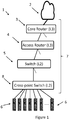
- Figure 1 is a schematic diagram of a traditional data center network.
- the data center (1) comprises a link to external networks (2), servers (6) and a switching hierarchy (7) comprising core routers (3), access routers (4), switches (5) cross point switches (8).
- FIG. 1 A major problem in such networks lies in large data flows, known as "elephant flows", which typically originate from server back-up, cloning, load balancing, backup, Virtual Machine migrations, or communication among memory banks and CPU in hyper scales data centers.
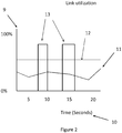
- Elephant flows are comparatively rare, but when they are present, they can dominate a data center network at the expense of smaller so-called “mice flows”. This can have a highly detrimental effect on the quality of service of mice flows, which are typically delay sensitive.
- Figure 2 is a graphical representation of "elephant” and “mice” flows. The graph shows network load (9) against time (10), with mice flows (11) below a threshold (12) and elephant flows (13) above the threshold. Although relatively rare, elephant flows cause major problems as they dominate the network and are highly detrimental to delay and delay variation in smaller flows.
- FIG 3 is a schematic diagram of an optical offload network for a data center network according to the prior art.
- an optical network 14
- Each rack of servers has a top of rack (ToR) switch (15), each of which is connected to the optical network (14).
- the optical network comprises an optical cross-connect (16) in the form of a Micro-electrical mechanical switch (MEMS).
- MEMS Micro-electrical mechanical switch
- a data center network node comprising at least one server connection for connecting to a server, and a connection for connecting the at least one server to a first subnetwork.
- the first subnetwork comprising at least one of a switch or a router.
- the node further comprising an electrical switching arrangement and at least one server connection for connecting the electrical switching arrangement to the at least one server.
- the node further comprising an optical receiver array for connecting the electrical switching arrangement to an optical offload subnetwork.
- the optical receiver array comprises a plurality of receivers.
- the node further comprising an optical transmitter array for connecting the electrical switching arrangement to an optical offload subnetwork.
- the optical transmitter array comprises a plurality of transmitters.
- the electrical switching arrangement is configured to direct an incoming data stream from a receiver in the optical receiver array to at least one of the at least one server connection or at least one transmitter in the optical transmitter array, and to direct an outgoing data stream from one of the at least one server connection to at least one transmitter in the optical transmitter array.
- the electrical switching arrangement is further configured to receive a data stream for a point to multipoint connection at one of the plurality of receivers, direct the data stream from the receiver to one of the at least one server connection, and direct the data stream to one or more of the plurality of transmitters.
- the electrical switching arrangement on receipt of a configuration instruction is configured to enable an incoming data stream to bypass the at least one server connection.
- the electrical switching arrangement is further configurable to: receive a first copy of a data stream for a point to multipoint connection at a first receiver; receive a second copy of the data stream for the point to multipoint connection at a second receiver; direct the data stream from the first receiver to one of the at least one servers; and direct the data stream from the second receiver to at least one transmitter
- the electrical switching arrangement provides for effective transport of data in a data center, e.g. transporting elephant flows on an optical offload network.
- the electrical switching arrangement enables the provision of point to multipoint connections for data streams by enabling a data stream to be passed to multiple transmitters or received at a node, sent to a server in the node, and transmitted to a subsequent node in the network.
- the optical electrical optical arrangement of the optical unit also provides "3R" regeneration of signals at each node.
- the optical receiver array is configured such that each receiver is connectable to an optical path within a multi-path optical connection and the optical transmitter array is configured such that each transmitter is connectable to an optical path within a multi-path optical connection.
- the first subnetwork comprises at least one of a switch or a router, an optical receiver array for connecting the node to an optical offload subnetwork.
- the optical receiver array comprises a plurality of optical receivers, the array being configured such that each receiver is connectable to an optical path within a multi-path optical connection, an optical transmitter array for connecting the node to an optical offload subnetwork.
- the optical transmitter array comprises a plurality of optical transmitters, the array being configured such that each receiver is connectable to an optical path within a multi-path optical connection.
- An electrical switching arrangement directs an incoming data stream from a receiver in the optical receiver array to either one of the at least one server connection or at least one transmitter in the optical transmitter array, and directs an outgoing data stream from one of the at least one servers to at least one transmitter in the optical transmitter array.
- the optical receiver array comprises a coupler for coupling the receivers to a multicore optical fiber and the optical transmitter array comprises a coupler for coupling the transmitters to a multicore optical fiber and the electrical switching arrangement is configurable to direct a data stream from one of the at least one servers to a plurality of transmitters.
- the data center network node is configured to buffer the data stream, transmit the data stream to a first of the plurality of transmitters, transmit the data stream to a second of the plurality of transmitters after a time delay and enable one or more of the transmitters and receivers, when not involved in a data stream transmission, to be put into an idle mode.
- a data center network comprising a first subnetwork, an optical offload subnetwork and a plurality of network nodes.
- the first subnetwork comprises at least one of a switch or a router.
- Each network node comprises at least one server connection for connecting to the at least one server, a data connection for connecting to the first subnetwork, an optical receiver array comprising a plurality of optical receivers, the array being configured such that each receiver is connectable to an optical path within a multi-path optical connection.
- the network further comprises an optical transmitter array comprising a plurality of optical transmitters, the array being configured such that each receiver is connectable to an optical path within a multi-path optical connection and an electrical switching arrangement for directing an incoming data stream from a receiver in the optical receiver array either, to one of the at least one servers, or to at least one transmitter in the optical transmitter array, and for directing an outgoing data stream from one of the at least one servers to at least one transmitter in the optical transmitter array and the optical offload subnetwork comprises a plurality of optical multi-path connections, each multi-path optical connection comprising a plurality of optical paths, the optical offload network being configured such that each node is connected to at least one other node by a multi-path optical connection.
- the multi-path optical connection with multiple optical paths allows not only higher capacity, but also enables point to multipoint connections to be established for data streams. For example, the arrangement enables point to multipoint connections where a time offset is required in the transmission of the data stream to different nodes.
- the data center network further comprises an orchestrator for scheduling transmission on the optical offload network, the orchestrator comprising a processor, a memory and a network interface card, the orchestrator being configured to set a threshold for identifying a data stream as a high bandwidth flow if the data stream has a capacity requirement higher than the threshold during a measurement period detect or determine high bandwidth flow demands by comparing capacity requirements of data stream with the threshold.
- an orchestrator for scheduling transmission on the optical offload network, the orchestrator comprising a processor, a memory and a network interface card, the orchestrator being configured to set a threshold for identifying a data stream as a high bandwidth flow if the data stream has a capacity requirement higher than the threshold during a measurement period detect or determine high bandwidth flow demands by comparing capacity requirements of data stream with the threshold.
- the network is further configured to construct a schedule for transmission of high bandwidth flows between network nodes in the optical offload subnetwork and identify two or more nodes through which a high bandwidth flow is to pass and provide instructions to provide each of the two or more nodes with one or more of a configuration instruction for an outgoing data stream which instructs the node to configure the electrical switching arrangement to direct the data stream from one of the at least one server to one or more optical paths in the outgoing multi-path optical connection and a configuration instruction for an incoming data stream which instructs the node to configure the electrical switching arrangement to direct the data stream from one or more optical paths in its incoming multi-path connection to at least one of at least one the server and/or to one or more optical paths in the outgoing optical multi-path connection.
- the electrical switching arrangement of at least one node is configurable to direct an outgoing data stream from one of the at least one servers to a plurality of transmitters in the optical transmitter array, such as to enable a point to multipoint connection for the data stream by copying the data stream to a plurality of transmitters at the at least one node.
- the electrical switching arrangement of at least one node is configurable to direct incoming an data stream from a receiver in the optical receiver array to one of the at least one servers and to at least one transmitter in the optical transmitter array, such as to enable a point to multipoint connection for the data stream by copying the data stream to the at least on server and to at least one server in at least one other node.
- a method of operating a data center network node comprising at least one server, and an incoming multi-path optical connection comprising a plurality of optical paths.
- An outgoing multi-path optical connection comprises a plurality of optical paths, an electrical switching arrangement for directing data streams between the optical paths on the incoming multi-path optical connection and the optical paths on the outgoing multi-path optical connection, and between the optical paths and at least one server.
- the method comprises, on receipt of a configuration instruction for an outgoing data stream, configuring the electrical switching arrangement to direct the data stream from one of the at least one server to one or more optical paths in the outgoing multi-path optical connection, and, on receipt of a configuration instruction for an incoming data stream, configuring the electrical switching arrangement to direct the data stream from one or more optical paths in its incoming multi-path connection to at least one of at least one the server and/or to one or more optical paths in the outgoing optical multi-path connection.
- the method further comprises, on receipt of a configuration instruction for an outgoing data stream associated with a point to multipoint connection, configuring the electrical switching arrangement to direct the data stream from one of the at least one server to a plurality of optical paths in the outgoing multi-path optical connection.
- the method further comprises, on receipt of a configuration instruction for an incoming data stream associated with a point to multipoint connection, configuring the electrical switching arrangement to direct the data stream from one or more optical paths in its incoming multi-path connection to at least one of at least one the server and to one or more optical paths in the outgoing optical multi-path connection and configuring the electrical switching arrangement enables an incoming data stream to bypass the server connection.
- the method further comprises implementing a first transmission of the data stream on a first optical path and implementing a second transmission of the data stream a second optical path with a time offset between the first transmission and the second transmission.
- the method further comprises putting into idle mode at least one receiver or transmitter which is not involved in a current transmission.
- a method of operating a data center network comprising a plurality of nodes linked by a first subnetwork comprising at least one of a switch or a router, and an optical offload subnetwork comprising a plurality of multi-path optical connections, wherein each node comprises at least one server, an incoming multi-path optical connection comprising a plurality of optical paths, an outgoing multi-path optical connection comprising a plurality of optical paths, an electrical switching arrangement for directing data streams between the optical paths and the at least one server, and a data connection for connecting the at least one server to the first subnetwork.
- the method comprises identifying a data stream, between a first server in an originating node and at least one server in at least one subsequent node, for offloading to the offload subnetwork, selecting a route through the offload network for the data stream. Selecting the route comprises and identifying one or more subsequent nodes and/or one or more multi-path connections, through which the data stream must be transmitted.
- the method further comprises, for each of the one or more multi-path connections, selecting one or more optical paths for carrying the data stream, instructing the originating node to configure its electrical switching arrangement to direct the data stream from the first server to each of the one or more selected optical paths in its outgoing multi-path optical connection, and instructing each of the one or more subsequent nodes, to configure its electrical switching arrangement to direct the data stream from each of selected optical paths in its incoming multi-path connection to the at least one server in the subsequent node and/or to an optical path in its outgoing multi-path optical connection.
- the method further comprises buffering the data stream in at least one node, transmitting the data stream to a node comprising a first receiving server; and after a time delay transmitting the data stream to a node comprising a second receiving server.
- the method further comprises developing a schedule for offloading data streams to the optical offload network.
- Developing of the schedule comprises constructing a booking list for high bandwidth flows, wherein a high bandwidth flow is a data stream which has a capacity requirement greater than a threshold, detecting or determining whether a data stream has a capacity requirement greater than the threshold and if it has, identifying the data stream as a high bandwidth flow and adding an identifier to the high bandwidth flow to the booking list determine whether the capacity and timing requirements of the high bandwidth flow can be satisfied by the optical offload network. If the capacity requirement can be met, the identifier to the high bandwidth flow is inserted into the schedule. The schedule is communicated to network nodes through which the high bandwidth flow is to pass.
- the method further comprises establishing a point to multipoint connection by instructing the originating node, to configure its electrical switching arrangement to direct the data stream from the first server to a plurality of selected optical paths in its outgoing multi-path optical connection.
- the method further comprises establishing a point to multipoint connection by instructing the originating node to configure its electrical switching arrangement to direct the data stream from the first server to a selected optical path in its outgoing multi-path optical connection and instructing at least one subsequent node to configure its electrical switching arrangement to direct the data stream from an optical paths in its incoming multi-path optical connection to both a to a server in the subsequent node and to an optical path in its outgoing multi-path optical connection.
- a computer program comprising instructions which, when executed on at least one processor, cause the at least one processor to carry out a method according to the third or fourth aspects.
- a computer program product comprising a computer program according to the fifth aspect.
- aspects of the present disclosure provide a cost effective optical offload network whilst allowing flexibility in providing optical links necessary for point-to-multipoint connections and to allow for regeneration of signals at intermediary nodes.
- the conventional subnetwork comprises the usual type of switched network used in a data center network, with either a hierarchical or flat arrangement of switches and/or routers.
- the person skilled in the art will appreciate that many different arrangements are possible for the conventional subnetwork and the invention is not limited to any particular arrangement of the conventional subnetwork.
- the optical offload subnetwork comprises an optical fiber network for providing point to point and point to multipoint links between nodes in order to transport high bandwidth flows between nodes. These optical offload links are separate from the conventional network.
- the data center network comprises a plurality of nodes, each comprising at least one server connection for connecting the node to servers, a connection for connecting to the conventional subnetwork, an electrical switching arrangement, an optical receiver array and an optical transmitter array. In an embodiment, the electrical switching arrangement and the transmitter/receiver arrays are configured as a single optical unit.
- the node is configured to enable connection of servers with either the conventional subnetwork or the offload subnetwork.
- the nodes are linked by an optical fiber multi-path connection comprising a plurality of optical paths.
- FIG. 4 is a schematic diagram of a data center network node according to an embodiment.
- the node (17) comprises at least one server connection (18) for connecting to a server (6), a connection (7) for connecting the server (6) to a conventional data center network comprising a switch or router and an optical unit (19).
- the at least one server connection (18) is for connecting the optical unit (19) to the server (6).
- the optical unit (19) comprises an optical receiver array (20) comprising a plurality of optical receivers (21), for linking the node to an incoming optical connection (22) and an optical transmitter array (23) comprising a plurality of optical transmitters (24) for connecting the node to an outgoing optical connection.
- the optical receivers are optical detectors or sensors, e.g. photodiodes and the transmitters are an optical light source, e.g. lasers.
- the optical receiver array (20) is configured to receive a plurality of optical signals, each optical signal being received over a different path of the multi-path connection.
- Each optical receiver (21) of the array (20) may be considered as is configured to receive one optical signal or configured to receive on one path of the multi-path signal.
- Each optical signal is independent of the other optical signals.
- One or more of the received optical signals may be the same or different to another optical signal.
- the optical transmitter array (23) is configured to transmit a plurality of optical signals, each optical signal being transmitted over a different path of the multi-path connection.
- Each optical transmitter (24) of the array (23) may be considered as is configured to transmit one optical signal or configured to transmit on one path of the multi-path signal.
- Each optical signal is independent of the other optical signals.
- One or more of the transmitted optical signals may be the same or different to another optical signal.
- each of the optical connections comprises a plurality of individual optical links.
- the optical unit (19) further comprises an electrical switching arrangement (26) for connecting the receivers and the transmitters with the server connection.
- the receivers (21) are configured to convert a received optical signal to an electrical signal.
- the electrical switching arrangement (26) is configured to switch the electrical signal to the server connection (18) for communication to the server, and/or to one or more transmitter (24).
- the transmitter (24) is configured to convert an electrical signal from the electrical switching arrangement (26) to an optical format for optical transmission to another node in the data center network.
- the electrical switching arrangement (26) may receive an electrical signal from either the receiver array (20) or the server connection (18), i.e. originating from a said server (6).
- the optical electrical optical arrangement of the optical unit provides "3R" regeneration of signals at each node.
- the electrical switching arrangement is configurable to enable a point to point connection between two nodes.
- the data stream originates at the first node and is directed by the first node's electrical switching arrangement (26) to one of its transmitters.
- the data stream is then carried on one of the paths in the outgoing optical connection from the first node.
- the data stream is detected by a receiver and transmitted (i.e. passed) by the electrical switching arrangement to the server connection (18) of the second node.
- each of these intermediate nodes configures its electrical switching arrangement so that the data stream bypasses the server connection of the intermediate node, i.e. the electrical switching arrangement is configured to switch a received signal from a receiver (21) directly to a transmitter (24).
- the electrical switching arrangement is configurable to receive a data stream for a point to multipoint connection at one of its receivers, and to direct the data stream from the receiver to one of the servers (6) in the node and/or to direct the data stream to one or more of its transmitters.
- a data stream arriving at one of the receivers may be both dropped (i.e. transmitted) to a server and/or passed to a subsequent node.
- the electrical switching arrangement is configured to transmit a received signal to the server connection (18). If there are further destination nodes on the point to multipoint path (i.e.
- the electrical switching arrangement is configured to also transmit the received signal to one or more of the transmitters (24).
- the electrical switching arrangement is configured to directly transmit the received signal, so that the data stream bypasses the server connection of the intermediate node.
- the electrical switching arrangement is configurable to implement point to multipoint connections by receiving an identical data stream from two different receivers, e.g. a first and second data stream. If the node receiving the first and second data stream is purely an intermediate node, then the electrical switching arrangement is configured so that the first and second data stream streams are directed to separate transmitters and hence to their respective destination nodes. If the node receiving the first and second data stream is a destination node and an intermediate node, then the electrical switching arrangement is configured so as to direct one of the data streams (e.g. first data stream) to the server connection (18) and the other (e.g. second data stream) to a transmitter for transmission to a subsequent node. More than two identical data streams may be received, in which case typically one may be dropped and the others transmitted to subsequent nodes.
- the optical offload network comprises an optical network for linking a plurality of data center nodes.
- the optical network is a ring network, although the person skilled in the art will appreciate that other network topologies such as a bus, a mesh or a star are also possible.
- the invention is not limited to any one optical topology.
- the network comprises an arrangement in which for each node, the transmitter array is connected to a receiver array of a second node by a first multi-path optical connection and the receiver array is connected to a transmitter array of a third node by a second multi-path optical connection.
- the ring provides a one way flow.
- each section between nodes may be bidirectional, either with separate fibers for each direction or with bidirectional transmission on a single fiber.
- the person skilled in the art will appreciate that there are a number of ways in which the optical network can be laid out and the invention is not limited to any one configuration.
- the optical connections between nodes comprises a multicore optical fiber.
- a single fiber connects a pair of nodes.
- one or more multicore optical fiber connects the optical units of the data center nodes.
- a multicore fiber is an optical fiber comprising a plurality of cores, each core providing a separate optical path.
- a MCF connects a first node and a second node.
- the first node comprises a connector to enable each transmitter (24) in the node's optical transmitter array (23) to be connected to a core of the multicore fiber.
- the node comprises a connector so that each core of the multicore optical fiber is connected to an optical receiver (21) of the optical receiver array (20).
- the multicore optical fiber carries independent optical signals along each core.
- Each core is separately connected to the transmitter array and receiver array of each of the nodes of the optical offload network.
- the cores of multicore optical fiber may be considered as paths of the multi-path connection.
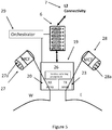
- FIG. 5 is a schematic diagram of a node connected to a multicore network according to an embodiment.
- an incoming optical connection (27) which comprises a multicore fiber (MCF) linked to the optical receiver array (20), labelled as a West (W) direction.
- the network further comprises an outgoing optical connection (28), which is linked to the optical transmitter array (23), labelled as an East (E) direction.
- An orchestrator (29) provides instructions to the node for configuring and control of the electrical switching arrangement (26).
- the MCFs 27,28 are illustrated as comprising a plurality of cores 27a,28a.
- the MCFs comprise seven cores 27a,28a, although any number of cores may be included in the MCF.
- Each core 27a,28a provides an independent optical path for transmission of data, within the same fiber.
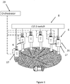
- FIG 6 is a schematic diagram of a data center network according to an embodiment. There is provided a plurality of network nodes (17), each comprising an optical unit (19) as described and connected by means of an optical offload network (30).
- the electrical switching arrangement (26) enables data streams to be sent from a first server (6) in a first network node (17) to a second server (6) in a second network node (17).
- a point to point configuration is established between the first and the second network nodes by means of the electrical switching arrangement (26) in the first node being arranged to connect the first server to a transmitter in the first node's transmitter array (24).
- a receiver in the receiver array (20) is connected to the second server by the electrical switching arrangement (26).
- the electrical switching arrangement (26) is configured to provide a link from a receiver in the received array to a transmitter in the transmitter array, so that the data stream bypasses the server connection of the intermediate node.
- the optical offload network (30) can be seen to provide a separate connection between servers (6) than the conventional switched connection. (8). This provides for efficient transport of elephant flows between nodes within a data center.
- FIG. 7 is a schematic diagram of the incoming connections within an electrical switching arrangement (26) according to an embodiment.
- the switching arrangement comprises a plurality of incoming electrical connections (31), each one being connected with an optical receiver (21), and a plurality of outgoing electrical connections (32), each one being connected to an optical transmitter (24).
- Two incoming data streams are illustrated, namely a first data stream (34) and a second data stream (35).
- the first data stream (34) is an incoming data stream destined for a server (6) in the node.
- the electrical switching arrangement (26) configures a link between the appropriate incoming connection (31) and an output (33) to the server connection.
- the second data stream (35) is destined for a different node and the electrical switching arrangement configures a connection from the incoming connection to an outgoing connection.
- the node is acting as an intermediate node and the data stream effectively bypasses the server connection of the node.
- the first and second data streams may be different, independent, data streams, with different destinations.
- first and second data streams may be data streams carrying the same data.
- the first data stream may be considered as a copy of the second data stream (or vice versa).
- This configuration of electrical switching arrangement (26) provides for a point-to-multipoint transmission.
- the first data stream (34) is to be dropped at the node to the server, as the node is a destination node of the point-to-multipoint transmission.
- the second data stream (35) is for onward transmission to another node of the optical offload network.
- one core of the MCG (or path) is used for each destination node.
- a plurality of cores are initially used for the point-to-multipoint transmission, and the number of cores utilized reduces by one after each destination node is reached by a copy of the point-to-multipoint transmission.
- the server connection (33) is a single link connecting the electrical switching arrangement to a top of rack switch or, optionally, to a single server if only one server is present at the node.
- the electrical switching arrangement comprises a plurality of server connections or outputs to a plurality of servers e.g. a full digital cross connect for connecting multiple servers to the receiver and transmitters.
- Figure 8 is a schematic diagram of a further example of the operation of an electrical switching arrangement according to an embodiment.
- Figure 8 shows an example of the configuration of the electrical switching arrangement to enable point-to-multipoint data streams to be established.
- Two data streams are illustrated, namely a third data stream (36) and a fourth data stream (39).
- the third data stream (36) is an incoming stream destined both for the node illustrated and for a subsequent node, received at the receiver array.
- the switching arrangement (26) is configured to direct the data stream (37) to the server connection (33) and also direct the data stream (38) to an outgoing connection, and hence to an optical transmitter of the transmitter array. Hence the data stream is both dropped to a server in the node and passed on for transmission to a subsequent node.
- This is an alternative configuration for providing for point-to-multipoint transmission.
- the electrical switching arrangement can also be configured so as to enable a data stream to be duplicated on another path.
- the fourth data stream (39) is directed (40) to a first transmitter and directed (41) to a second transmitter.
- the data stream is duplicated onto one more further paths (cores).
- This is an alternative configuration for providing for point-to-multipoint transmission. For example, this allows a point-to-multipoint to be set up in an instance where the originating node has a shortage of available outgoing links (e.g. only one core or path is required for the initial transmission on the point-to-multipoint path until this intermediate node).
- FIG 9 is a schematic diagram showing the handling of outgoing data streams according to an embodiment.
- a single data stream (42) from a server in the node is shown, which is destined for a single destination server in another node.
- the electrical switching arrangement configures a connection to link the server connection (33), corresponding to server connection (18), to an outgoing connection providing for transmission from an optical transmitter (32) of the optical transmitter array (24).
- FIG 10 is a schematic diagram showing the handling of outgoing data streams according to a further embodiment.
- a point-to-multipoint connection for a data stream originating at the illustrated node is required.
- the electrical switching arrangement is configured to provide multiple connections (43, 44, 45) from the server connection (33), corresponding to server connection (18), to a plurality of outgoing connections, i.e. a plurality of transmitters (24) of the transmitter array. This enables the data stream to be transmitted to multiple nodes on different optical cores of a MCF (or paths or links).
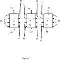
- FIG 11 is a schematic diagram illustrating the connection arrangements for a plurality of network nodes (46, 47, 48).
- the data stream commences at a first node (46), bypasses the server connection of a second node (47) and is terminated at a third node (48).
- the switching arrangement of the first node (46) is configured to provide a connection (49) for the data stream from the server connection to a transmitter.
- the switching arrangement of the second node (47) is configured to provide a bypass (50) for the data stream, e.g. bypassing of the server (6).
- the switching arrangement of the third node (48) is configured to provide a connection (51) between a receiver and the server connection for the data stream.
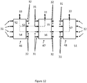
- Figure 12 is a schematic diagram illustrating a further example of the connection arrangements for a plurality of network nodes (46, 47, 48) according to an embodiment.
- This example shows a point to multipoint connection from the first node (46).
- a data stream (52) is intended to be transmitted on the point-to-multipoint connection to two further nodes, second node (47) and third node (48). The data stream is to be transmitted on a separate path for each destination.
- the data stream (52) from the first node is sent to a first outgoing paths (53), which is destined for the second node (47) and a second outgoing path (54) which is destined for the third node (48).
- a first outgoing paths (53) which is destined for the second node (47)
- a second outgoing path (54) which is destined for the third node (48).
- the first connection is terminated and sent to the server connection (55) and the second connection bypasses the node (56).
- the second connection is directed (57) to the server connection.
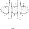
- FIG 13 is a schematic diagram illustrating an alternative method of implementing a point-to-multipoint connection.
- a data stream (58) is destined to two other nodes, a second node (47) and a third node (48).
- the data stream (58) is sent only to one transmitter.
- the data stream is dropped (59) to the server connection and to an outgoing transmitter (60).
- the data stream is sent (61) to the server connection.
- An advantage of method of Figure 12 is that the data stream may be sent to different nodes at different points in time. For example it may be necessary to send a data stream to two different nodes with a time offset between the transmissions. This may be due for example to one of the receiving servers being occupied with a previously scheduled transmission.
- the advantage of the scheme of Figure 13 is that only one link from a node is occupied for a single data stream.
- the person skilled in the art will appreciate that the two techniques may be used separately or together in the same transmission scheduling. For example a data stream may be scheduled to be three receiving servers. One of the receiving servers may require a time offset for receiving the data stream. In this instance, the technique of Figure 12 may be used for the server requiring the time offset and the technique of Figure 13 used for the other two servers.
- Figure 14 is a flow chart illustrating a method of operating a data center node according to an embodiment.
- the method comprises configuring (64) the electrical switching arrangement to direct the data stream from one or more optical paths (e.g. cores of a MCF) in its incoming multi-path connection to at least one of at least one the server and/or to one or more optical paths in the outgoing optical multi-path connection.
- the method further comprises receiving a configuration instruction (65) for an outgoing data stream, the method comprises configuring (66) the electrical switching arrangement to direct the data stream from one of the at least one server to one or more optical paths in the outgoing multi-path optical connection.
- the electrical switching arrangement is configured to direct the data stream from one or more optical paths in its incoming multi-path connection to at least one of at least one the server and to one or more optical paths in the outgoing optical multi-path connection.
- the electrical switching arrangement is configured to direct the data stream from one of the at least one server to a plurality of optical paths in the outgoing multi-path optical connection.
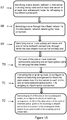
- Figure 15 is a flow chart of a method of operating a data center network according to an embodiment.
- the method may be implemented by the orchestrator or other management or control entity.
- the method starts by identifying (67) a data stream, between a first server in an originating node and at least one server in at least one subsequent node, for offloading to the offload subnetwork.
- a route is selected (68) through the offload network for the data stream.
- the selection of the route comprises identifying (69) one or more subsequent nodes and/or one or more multi-path connections, through which the data stream must be transmitted.
- the originating node is instructed (71) to configure its electrical switching arrangement to direct the data stream from the first server to each of the one or more selected optical paths in its outgoing multi-path optical connection.
- Each of the one or more subsequent nodes is instructed (72) to configure its electrical switching arrangement to direct the data stream from each of selected optical paths in its incoming multi-path connection to a server in the subsequent node and/or to an optical path in its outgoing optical connection.
- a data stream may be sent to a first server in a first node and, with a time offset to a second node in a second node.
- the method requires all of the steps of the embodiment of Figure 15 .
- Figure 16 is a flow chart illustrating the further steps required for this embodiment.
- the data stream is buffered (73) in at least one node. In an embodiment, this is the originating node, but the person skilled in the art will appreciate that the buffering may take place at any intermediate node. The invention is not limited to any location of the buffering.
- the data stream is then transmitted (74) to the node comprising the first receiving server. After a time delay the data stream is transmitted (75) to the node comprising the second receiving server.
- the buffering provides for a time delay to avoid conflict with another transmission or processing function.
- an elephant flow In order to configure the offload subnetwork, there is a requirement to identify which flows are to be offloaded onto the optical offload subnetwork.
- the quantitative definition of an elephant flow can be determined by network operators according to criteria. High bandwidth flows or "elephant flows" are those that send more than a given threshold of the link capacity, during a given measurement interval.
- a flow is a set of packets that match the same properties, such as source/destination TCP ports.
- an elephant flow or high bandwidth flow is any flow which is identified as requiring more than a given threshold of network capacity.
- high bandwidth flows which may be offloaded onto the offload subnetwork are identified by using a threshold related to network capacity.
- this threshold relates to available bandwidth. Flows which have a bandwidth requirement above the threshold are designated as high bandwidth flows and the capacity demands associated with them are referred to as high bandwidth flow demands.
- the threshold may be set by the operator or set in a default. The person skilled in the art will appreciate that there are different options for the level of the threshold, the means of setting the threshold and network parameter to which the threshold relates. The invention is not limited to any one level of threshold, means of setting the threshold or network parameter to which it relates.
- a schedule of logical links between the nodes of the network is constructed so as to enable the high bandwidth flows to be transmitted on the offload network.
- the schedule of logical links comprises a list of pairs of nodes, the originating node and the terminating node, to be linked, the order in which they are to be linked and the duration of the logical links.
- the schedule comprises a list of pairs of nodes or an originating node and a plurality of terminating nodes, in the case of point-to-multipoint connections. In each case, intermediate nodes and/or optical connection to be used between the originating and terminating nodes must be identified.
- this schedule is based on an indication of the amount of data estimated for each flow and the nodes between which the flow is required to be transmitted.
- the time required for the flow may not be known a priori as this depends on the bit rate of the connection.
- the traffic demand can have additional constraints, such as maximum latency, time limit for transmission etc.
- this schedule is constructed based on the bandwidth requirements of each of the high bandwidth flow demands.
- the delay sensitivity of the flows is considered when scheduling the order and duration of the logical links.
- the delay variation sensitivity of the flows is considered when scheduling the order and duration of the logical links.
- the presence of an optical offload may not guarantee that all high bandwidth flows are enabled to use the offload.
- the conventional subnetwork is available and the inability to offload does not mean that data is lost.
- the option of using the conventional subnetwork means that, in an embodiment, this can be incorporated into the offload scheduling.
- Figure 17 is a flowchart illustrating a method of developing a schedule (76) for offloading data streams to the optical offload network.
- the method may be implemented in the orchestrator or other management or control entity.
- the development of the schedule comprises constructing (77) a booking list for high bandwidth flows, wherein a high bandwidth flow is a data stream which has a capacity requirement greater than a threshold.
- the next step is to detect or determine (78) whether a data stream has a capacity requirement greater than the threshold and if it has, identifying the data stream as a high bandwidth flow and adding an identifier to the high bandwidth flow to the booking list. It is next determined (79) whether the capacity and timing requirements of the high bandwidth flow can be satisfied by the optical offload network. If the capacity requirement can be met (80), inserting the identifier to the high bandwidth flow into the schedule.
- the schedule is then communicated (81) to network nodes through which the high bandwidth flow is to pass.
- Figure 18 is a flow chart of managing a booking list according to an embodiment.
- the method may be implemented in the orchestrator or other management or control entity.
- a determination (82) is made as to whether there is at least one new available optical path (for example one arc on a core on a ring not used for traffic) or whether a new high elephant flow, EF, or collection of elephant flows, CEF, has been added to the booking list and that at least one optical path is still available. If this condition is not met (83), the method continues to make the determination. If the condition is met (84), the booking list is frozen (85). A determination is then made as to whether there is an EF or a CEF in the booking list which is compatible with the available paths (86).
- the booking list is unfrozen (90). If yes (88), then the EF or CEF is served on the available path or paths (89) and the booking list is unfrozen (91). It is then determined (92) whether one or more entries of the overbooking section can be moved to the ordinary booking list or eventually refused. The booking list is then reshuffled if necessary (93).
- Figure 19 is a flow chart showing the steps of such a scheduling method according to an embodiment.
- a high bandwidth flow demand is detected or determined (94).
- the high bandwidth flow is then analyzed (95).
- This analysis can comprise determining total data flow requirements, latency, time limits etc.
- the orchestrator has three options. These options are to refuse the use of the offload subnetwork (96), to insert the high bandwidth flow demand into a booking list (97) for construction of the schedule of logical links and to accept the high bandwidth flow demand into an "overbooking" section of the booking list (98).
- the person skilled in the art will appreciate that all combinations of these options may be used and the invention is not limited to any one combination of options.
- the transmitter or receiver when an optical transmitter or receiver is not involved in the transmission of a data stream, the transmitter or receiver is maintained in an idle mode in order to save energy. Transitions between the normal operating mode and the idle mode (and vice versa) waste time and hence network capacity, especially in case of high bit rates transmission. As a consequence, number of transitions should be minimized. In an embodiment, the booking list for the offload subnetwork is organized so as to minimize such transitions.
- servers are polled to determine their data requirements.
- high bandwidth flows may be detected at the cross point switches.
- planned data flows such as backup or virtual machine migration may be used.
- combinations of these techniques may be used. The person skilled in the art will appreciate that there are many options for determining or detecting high bandwidth flows and the invention is not limited to any one method.
- the data center network comprises an orchestrator which detects high bandwidth or elephant flows and schedules their transmission on the optical offload network.
- the nodes are configured to receive instructions from the orchestrator. In alternative embodiments, a more distributed system of control is provided.
- FIG 20 is a schematic diagram illustrating the components of an orchestrator (99) according to an embodiment.
- a memory for storing instructions (101)
- a processor for implementing the instructions
- a plurality of network interfaces (105) for receiving data
- a bus for connecting the components of the orchestrator.
- the processor which may alternatively be termed a processing circuitry, may comprise one or more microprocessors, microcontrollers, hardware circuits, discrete logic circuits, hardware registers, digital signal processors (DSPs), field-programmable gate arrays (FPGAs), application-specific integrated circuits (ASICs), or a combination thereof.
- the processing circuitry may be programmable hardware capable of executing machine instructions stored as a machine-readable computer program in the memory, which may alternatively be termed a memory circuitry.
- the memory circuitry of the various embodiments may comprise any non-transitory machine-readable media known in the art or that may be developed, including but not limited to magnetic media (e.g., floppy disc, hard disc drive, etc.), optical media (e.g., CD-ROM, DVD-ROM, etc.), solid state media (e.g., SRAM, DRAM, DDRAM, ROM, PROM, EPROM, Flash memory, solid state disc, etc.), or the like.
- magnetic media e.g., floppy disc, hard disc drive, etc.
- optical media e.g., CD-ROM, DVD-ROM, etc.
- solid state media e.g., SRAM, DRAM, DDRAM, ROM, PROM, EPROM, Flash memory, solid state disc, etc.
- the orchestrator may comprise a computer program, comprising instructions which, when executed on the at least one processor, causes the at least one processor to carry out a method according to any example.
- a computer program product comprises a computer program according to any example.
- the network node comprises a processor, memory and optionally further elements described in Figure 20 .
- the processor may be configured to receive control instructions, e.g. from the orchestrator, and provide one or more output to configure the electrical switching arrangement according to any example.
- This local control of the electrical switching arrangement e.g. by a controller of the electrical switching arrangement, may be considered as a part of the electrical switching arrangement, and is not shown separately.
- the orchestrator is configured to set a threshold for identifying a data stream as a high bandwidth flow if the data stream has a capacity requirement higher than the threshold during a measurement period, detect or determine high bandwidth flow demands by comparing capacity requirements of data stream with the threshold and construct a schedule for transmission of high bandwidth flows between network nodes in the optical offload subnetwork.
- the orchestrator is further configured to identify two or more nodes through which a high bandwidth flow is to pass and provide instructions to provide each of the two or more nodes with one or more of:
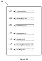
- FIG 21 is a schematic diagram of units for use in an orchestrator (99) according to an embodiment.
- the orchestrator comprises a threshold unit (107) for setting a threshold for identifying a flow demand as a high bandwidth flow if the flow demand has a capacity requirement higher than the threshold during a measurement period.
- the orchestrator comprises a determining unit (106) for detecting or determining high bandwidth flow demands by comparing capacity requirements of flow demands with the threshold.
- the orchestrator comprises a scheduling unit (109) for constructing a schedule of logical links for transmission of high bandwidth flows between network nodes in the offload subnetwork.
- the orchestrator further comprises an analyzing unit (110) for analyzing each high bandwidth flow demand.
- the orchestrator comprises a decision unit (111) for, on the basis of the analyzing, performing one of three operations: denying optical offload, inserting the high bandwidth flow demand into a booking list and inserting the high bandwidth flow demand into an overbooking list.
- the orchestrator further comprises a booking list arranging unit (112) for moving a second high bandwidth flow demand in the booking list into a first position.
- the orchestrator comprises a re-scrambling unit (113) for determining if the list may be re-scrambled and determining if one or more entries in the overbooking list may be moved to the booking list or refused.
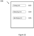
- Figure 22 is a schematic diagram of the units for use in a determining unit for an orchestrator according to an embodiment.
- the determining unit comprises a polling unit (113) for periodically polling of network nodes.
- the determining unit comprises a detecting unit (114) for detecting high bandwidth flow demands at a cross-point switch.
- the determining unit comprises an identifying unit (115) for identifying high bandwidth flow demands from planned data transfers.
- the person skilled in the art will appreciate that any combination of the polling unit, the detecting unit and the identifying unit may be used. The invention is not limited to any one unit or combination of units.
- an orchestrator for controlling optical offloads in a data center network according to an embodiment.
- the orchestrator comprises the following functional items: a threshold unit for setting a threshold for identifying a data stream as a high bandwidth flow if the data stream has a capacity requirement higher than the threshold during a measurement period; a determining unit for detecting or determining high bandwidth flow demands by comparing capacity requirements of data stream with the threshold; and a scheduling unit for constructing a schedule for transmission of high bandwidth flows between network nodes in the optical offload subnetwork.
- the orchestrator optionally further comprises an analyzing unit for analyzing each high bandwidth flow demand; and a decision unit for, on the basis of the analyzing, performing one of three operations: denying optical offload, inserting the high bandwidth flow demand into a booking list and inserting the high bandwidth flow demand into an overbooking list.
- the orchestrator optionally further comprises: a booking list arranging unit for moving a second high bandwidth flow demand in the booking list into a first position; and a shuffling unit for determining if the list may be shuffled and determining if one or more entries in the overbooking list may be moved to the booking list or refused.
- the orchestrator optionally further comprises a polling unit for periodically polling of network nodes.
- the determining unit comprises a detecting unit for detecting high bandwidth flow demands at a cross-point switch.
- the determining unit comprises an identifying unit for identifying high bandwidth flow demands from planned data transfers.
- the disclosure provides an orchestrator configured to control an electrical switching arrangement for an optical offload network of a data center node, the orchestrator comprising processing circuitry, configured by executable instructions in a memory to implement the method of any example.
- the disclosure provides network node, or an optical unit, configured to control an electrical switching arrangement for an optical offload network of a data center node, the orchestrator comprising processing circuitry, configured by executable instructions in a memory to implement the method of any example.
- a further embodiment uses a single core optical fiber in conjunction with wavelength division multiplexing.
- each transmitter transmits with a different wavelength.
- the transmitter array is provided with a wavelength division multiplexer to couple the transmitter wavelengths into the fiber.
- a wavelength division de-multiplexer is provided couple the incoming wavelengths to the receivers in the receiver array.
- tunable lasers are used to provide different wavelengths.
- multiple optical fibers are used to provide multiple paths between nodes. Each of these options provides the required multi-path connections which link the nodes.
- Each multi-path connection comprises a plurality of optical links.
- the multipath connection is the multicore fiber and each core in the fiber provides a link.
- the fiber is the multi-path connection and each of the wavelengths provides a link.
Landscapes
- Engineering & Computer Science (AREA)
- Computer Networks & Wireless Communication (AREA)
- Signal Processing (AREA)
- Computing Systems (AREA)
- Physics & Mathematics (AREA)
- Electromagnetism (AREA)
- Data Exchanges In Wide-Area Networks (AREA)
- Small-Scale Networks (AREA)
Claims (13)
- Nœud de réseau de centre de données (17), comprenant :une connexion (7) pour connecter au moins un serveur (6) à un premier sous-réseau, le premier sous-réseau comprenant au moins un d'un commutateur ou d'un routeur ; etun agencement de commutation électrique (26) ;au moins une connexion de serveur (18) pour connecter l'agencement de commutation électrique à l'au moins un serveur (6) ;un réseau de récepteurs optiques (20) pour connecter l'agencement de commutation électrique (26) à un sous-réseau de délestage optique ;dans lequel le réseau de récepteurs optiques (20) comprend une pluralité de récepteurs ;un réseau de transmetteurs optiques (23) pour connecter l'agencement de commutation électrique (26) au sous-réseau de délestage optique ;dans lequel le réseau de transmetteurs optiques (23) comprend une pluralité de transmetteurs ;dans lequel l'agencement de commutation électrique est configuré pour au moins un de :orienter un flux entrant de données depuis un récepteur (21) dans le réseau de récepteurs optiques (20) vers au moins une de l'au moins une connexion de serveur (18) ou au moins un transmetteur (24) dans le réseau de transmetteurs optiques (23), et pour orienter un flux sortant de données depuis une de l'au moins une connexion de serveur (18) vers au moins un transmetteur (24) dans le réseau de transmetteurs optiques (23), etrecevoir un flux de données, pour une connexion point à multipoint, au niveau d'un de la pluralité de récepteurs (21), orienter le flux de données depuis le récepteur vers une de l'au moins une connexion de serveur (18), et orienter le flux de données vers un ou plusieurs de la pluralité de transmetteurs (24) ;dans lequel l'agencement de commutation électrique (26) est configuré pour permettre à un flux entrant de données de contourner l'au moins une connexion de serveur (18) et dans lequel l'agencement de commutation électrique est, lors de la réception d'une instruction de configuration, en outre configurable pour :recevoir une première copie d'un flux de données, pour une connexion point à multipoint, au niveau d'un premier récepteur ;recevoir une seconde copie des flux de données, pour la connexion point à multipoint, au niveau d'un second récepteur ;orienter le flux de données depuis le premier récepteur vers un de l'au moins un serveur ; etorienter le flux de données depuis le second récepteur vers au moins un transmetteur.
- Nœud de réseau de centre de données (17) selon la revendication 1, dans lequel le réseau de récepteurs optiques (20) est configuré de telle sorte que chaque récepteur soit connectable à un trajet optique à l'intérieur d'une connexion optique à trajets multiples et le réseau de transmetteurs optiques (23) est configuré de telle sorte que chaque transmetteur soit connectable à un trajet optique à l'intérieur d'une connexion optique à trajets multiples, et/ou dans lequel le réseau de récepteurs optiques (20) comprend un connecteur pour connecter les récepteurs à une fibre optique à âmes multiples et le réseau de transmetteurs optiques (23) comprend un coupleur pour coupler les transmetteurs à une fibre optique à âmes multiples, et/ou dans lequel l'agencement de commutation électrique (26) est configurable pour orienter un flux de données depuis une de l'au moins une connexion de serveur (18) vers une pluralité de transmetteurs.
- Nœud de réseau de centre de données (17) selon la revendication 2, en outre configuré pour :mettre en mémoire tampon le flux de données ;transmettre le flux de données à un premier de la pluralité de transmetteurs ;transmettre le flux de données à un second de la pluralité de transmetteurs après un retard, et/oupermettre à un ou plusieurs transmetteurs et récepteurs, lorsqu'ils ne sont pas impliqués dans une transmission de flux de données, d'être mis dans un mode inactif.
- Réseau de centre de données, comprenant un premier sous-réseau, un sous-réseau de délestage optique et une pluralité de nœuds de réseau (17), dans lequel :le premier sous-réseau comprend au moins un d'un commutateur ou d'un routeur ;chaque nœud de réseau comprend une connexion pour connecter l'au moins un serveur (6) au premier sous-réseau, un agencement de commutation électrique (26), au moins une connexion de serveur (18) pour connecter l'agencement de commutation électrique (26) à l'au moins un serveur, un réseau de récepteurs optiques (20) pour connecter l'agencement de commutation électrique au sous-réseau de délestage optique, un réseau de transmetteurs optiques (23) pour connecter l'agencement de commutation électrique au sous-réseau de délestage optique,dans lequel l'agencement de commutation électrique est configuré pour orienter un flux entrant de données depuis un récepteur dans le réseau de récepteurs optiques (20) vers au moins une de l'au moins une connexion de serveur (18) ou au moins un transmetteur dans le réseau de transmetteurs optiques et pour orienter un flux sortant de données depuis une de l'au moins une connexion de serveurs vers au moins un transmetteur dans le réseau de transmetteurs optiques ; etle sous-réseau de délestage optique comprend une pluralité de connexions optiques à trajets multiples, chaque connexion optique à trajets multiples comprenant une pluralité de trajets optiques, le réseau de délestage optique (30) étant configuré de telle sorte que chaque nœud soit connecté à au moins un autre nœud par une connexion optique à trajets multiples ;dans lequel le réseau de centre de données comprend en outre un orchestrateur (29, 99) pour ordonnancer la transmission sur le réseau de délestage optique (30), l'orchestrateur comprenant un processeur, une mémoire (100) et une carte d'interface de réseau (105), l'orchestrateur étant configuré pour :régler un seuil pour identifier un flux de données en tant que flux à haute largeur de bande si le flux de données a une condition de capacité supérieure au seuil durant une période de mesure ;la détection ou la détermination de demandes de flux à haute largeur de bande en comparant des conditions de capacité de flux de données au seuil ;construire un ordonnancement pour la transmission de flux à haute largeur de bande entre des nœuds de réseau dans le sous-réseau de délestage optique ; etidentifier deux, ou plus, nœuds à travers lesquels un flux à haute largeur de bande doit passer et fournir des instructions pour fournir, à chacun des deux, ou plus, nœuds, une ou plusieurs de :une instruction de configuration pour un flux sortant de données qui donne l'instruction au nœud de configurer l'agencement de commutation électrique (26) pour orienter le flux de données depuis un de l'au moins un serveur (6) vers un ou plusieurs trajets optiques dans la connexion optique sortante à trajets multiples ; etune instruction de configuration pour un flux entrant de données qui donne l'instruction au nœud de configurer l'agencement de commutation électrique (26) pour orienter le flux de données depuis un ou plusieurs trajets optiques dans sa connexion entrante à trajets multiples vers au moins un de l'au moins un serveur (6) et/ou vers un ou plusieurs trajets optiques dans la connexion optique entrante à trajets multiples.
- Réseau de centre de données selon la revendication 4, dans lequel l'agencement de commutation électrique (26) d'au moins un nœud est configurable pour orienter un flux sortant de données depuis un de l'au moins un serveur vers une pluralité de transmetteurs dans le réseau de transmetteurs optiques, par exemple pour permettre une connexion point à multipoint, pour le flux de données, en copiant le flux de données, à une pluralité de transmetteurs, au niveau de l'au moins un nœud.
- Réseau de centre de données selon l'une quelconque des revendications 4 à 5, dans lequel l'agencement de commutation électrique (26) d'au moins un nœud est configurable pour orienter un flux entrant de données depuis un récepteur dans le réseau de récepteurs optiques (20) vers un de l'au moins un serveur et vers au moins un transmetteur dans le réseau de transmetteurs optiques (23), par exemple pour permettre une connexion point à multipoint, pour le flux de données, en copiant le flux de données, à l'au moins un serveur (6) et à au moins un serveur dans au moins un autre nœud.
- Procédé de fonctionnement d'un nœud de réseau de centre de données (17), le nœud comprenant une connexion pour connecter au moins un serveur (6) au premier sous-réseau, un agencement de commutation électrique, au moins une connexion de serveur (18) pour connecter l'agencement de commutation électrique (26) à l'au moins un serveur, un réseau de récepteurs optiques (20) pour connecter l'agencement de commutation électrique (26) à un sous-réseau de délestage optique, un réseau de transmetteurs optiques (23) pour connecter l'agencement de commutation électrique (26) au sous-réseau de délestage optique, dans lequel l'agencement de commutation électrique est configuré pour orienter un flux entrant de données depuis un récepteur dans le réseau de récepteurs optiques vers au moins une de l'au moins une connexion de serveur (18) ou au moins un transmetteur dans le réseau de transmetteurs optiques et pour orienter un flux sortant de données depuis une de l'au moins une connexion de serveurs vers au moins un transmetteur dans le réseau de transmetteurs optiques, le procédé comprenant :
lors de la réception d'une instruction de configuration pour un flux sortant de données :la configuration (66) l'agencement de commutation électrique (26) pour orienter le flux de données depuis un de l'au moins un serveur(6) vers un ou plusieurs trajets optiques dans la connexion optique sortante à trajets multiples ;lors de la réception d'une instruction de configuration pour un flux entrant de données :la configuration (64) de l'agencement de commutation électrique (26) pour orienter le flux de données depuis un ou plusieurs trajets optiques dans sa connexion entrante à trajets multiples vers au moins un de l'au moins un serveur (6) et/ou vers un ou plusieurs trajets optiques dans la connexion optique sortante à trajets multiples ;lors de la réception d'une instruction de configuration pour un flux sortant de données associé à une connexion point à multipoint :la configuration (66) de l'agencement de commutation électrique (26) pour orienter le flux de données depuis un de l'au moins un serveur (6) vers une pluralité de trajets optiques dans la connexion optique sortante à trajets multiples ; etlors de la réception d'une instruction de configuration pour un flux entrant de données associé à une connexion point à multipoint :la configuration (64) de l'agencement de commutation électrique pour orienter le flux de données depuis un ou plusieurs trajets optiques dans sa connexion entrante à trajets multiples vers au moins un de l'au moins un serveur (6) et vers un ou plusieurs trajets optiques dans la connexion optique sortante à trajets multiples,dans lequel la configuration de l'agencement de commutation électrique (26) permet à un flux entrant de données de contourner la connexion de serveur (18). - Procédé selon la revendication 7, le procédé comprenant en outre :l'implémentation d'une première transmission des flux de données sur un premier trajet optique ;l'implémentation d'une seconde transmission des flux de données sur un second trajet optique avec un décalage temporel entre la première transmission et la seconde transmission, et/oula mise, dans un mode inactif, d'au moins un récepteur ou transmetteur qui n'est pas impliqué dans la transmission d'un flux de données.
- Procédé de fonctionnement d'un réseau de centre de données, le réseau comprenant une pluralité de nœuds liés par : un premier sous-réseau comprenant au moins un d'un commutateur ou d'un routeur, et le sous-réseau de délestage optique comprenant une pluralité de connexions optiques à trajets multiples, dans lequel chaque nœud comprend une connexion pour connecter au moins un serveur (6) au premier sous-réseau, un agencement de commutation électrique (26), au moins une connexion de serveur (18) pour connecter l'agencement de commutation électrique (26) à l'au moins un serveur, un réseau de récepteurs optiques (20) pour connecter l'agencement de commutation électrique (26) au sous-réseau de délestage optique, un réseau de transmetteurs optiques (23) pour connecter l'agencement de commutation électrique (26) au sous-réseau de délestage optique, dans lequel l'agencement de commutation électrique (26) est configuré pour orienter un flux entrant de données depuis un récepteur dans le réseau de récepteurs optiques vers au moins une de l'au moins une connexion de serveur (18) ou au moins un transmetteur dans le réseau de transmetteurs optiques, et pour orienter un flux sortant de données depuis une de l'au moins une connexion de serveurs (18) vers au moins un transmetteur dans le réseau de transmetteurs optiques, le procédé comprenant :l'identification (67) d'un flux de données, entre un premier serveur dans un nœud d'origine et au moins un serveur dans au moins un nœud subséquent, pour le délestage sur le sous-réseau de délestage ;la sélection (68) d'une route à travers le réseau de délestage, pour le flux de données, dans lequel la sélection de la route comprend :l'identification (69) d'un ou de plusieurs nœuds subséquents et/ou d'une ou de plusieurs connexions à trajets multiples, à travers lesquels le flux de données doit être transmis ; etpour chacune des une ou plusieurs connexions à trajets multiples, la sélection (70) d'un ou de plusieurs trajets optiques pour transporter le flux de données ;l'instruction (71), au nœud d'origine, de configurer son agencement de commutation électrique (26) pour orienter le flux de données depuis le premier serveur vers chacun des un ou plusieurs trajets optiques sélectionnés dans sa connexion optique sortante à trajets multiples ; etl'instruction (72), à chacun des un ou plusieurs nœuds subséquents, de configurer son agencement de commutation électrique (26) pour orienter le flux de données depuis chacun de trajets optiques sélectionnés dans sa connexion optique à trajets multiples entrants vers l'au moins un serveur dans le nœud subséquent et/ou vers un trajet optique dans sa connexion optique sortante à trajets multiples.
- Procédé selon la revendication 9, dans lequel le flux de données doit être transmis à une pluralité de serveurs de réception, le procédé comprenant en outre :la mise en mémoire tampon (73) du flux de données dans au moins un noeud ;la transmission (74) du flux de données à un nœud comprenant un premier serveur de réception ; etaprès un retard, la transmission (75) du flux de données à un nœud comprenant un second serveur de réception.
- Procédé selon la revendication 9 ou 10, dans lequel une pluralité de flux de données doivent être transmis, le procédé comprenant en outre :
le développement (76) d'un ordonnancement pour le délestage de flux de données sur le réseau de délestage optique (30), dans lequel le développement de l'ordonnancement comprend :la construction (77) d'une liste de réservation pour des flux à haute largeur de bande, dans lequel un flux à haute largeur de bande est un flux de données qui a une condition de capacité supérieure à un seuil ;la détection ou la détermination (78) du fait qu'un flux de données a, ou n'a pas, une condition de capacité supérieure au seuil, et, dans l'affirmative, l'identification du flux de données en tant que flux à haute largeur de bande et l'ajout d'un identifiant pour le flux à haute largeur de bande à la liste de réservation ;la détermination (79) du fait que les conditions de capacité et de synchronisation du flux à haute largeur de bande peuvent, ou ne peuvent pas, être respectées par le réseau de délestage optique (30) ;si la condition de capacité peut être respectée, l'insertion (80) de l'identifiant dans le flux à haute largeur de bande dans l'ordonnancement ;la communication (81) de l'ordonnancement à des nœuds de réseau à travers lesquels le flux à haute largeur de bande doit passer ; et/oul'établissement d'une connexion point à multipoint en donnant l'instruction, au nœud d'origine, de configurer son agencement de commutation électrique (26) pour orienter le flux de données depuis le premier serveur vers :une pluralité de trajets optiques sélectionnés dans sa connexion optique sortante à trajets multiples, et/ouun trajet optique sélectionné dans sa connexion optique sortante à trajets multiples, etl'instruction, à au moins un nœud subséquent, de configurer son agencement de commutation électrique (26) pour orienter le flux de données depuis un trajet optiques dans sa connexion optique à trajets multiples entrants à la fois vers l'au moins un serveur dans le nœud subséquent et vers un trajet optique dans sa connexion optique sortante à trajets multiples. - Programme d'ordinateur, comprenant des instructions qui, lorsqu'elles sont exécutées sur au moins un processeur, font en sorte que l'au moins un processeur réalise un procédé selon l'une quelconque des revendications 7 à 11.
- Produit programme d'ordinateur, comprenant un programme d'ordinateur selon la revendication 12.
Applications Claiming Priority (1)
| Application Number | Priority Date | Filing Date | Title |
|---|---|---|---|
| PCT/EP2016/059207 WO2017186265A1 (fr) | 2016-04-25 | 2016-04-25 | Réseau de centre de données |
Publications (2)
| Publication Number | Publication Date |
|---|---|
| EP3449603A1 EP3449603A1 (fr) | 2019-03-06 |
| EP3449603B1 true EP3449603B1 (fr) | 2020-08-26 |
Family
ID=55970962
Family Applications (1)
| Application Number | Title | Priority Date | Filing Date |
|---|---|---|---|
| EP16722808.9A Not-in-force EP3449603B1 (fr) | 2016-04-25 | 2016-04-25 | Réseau de centre de données |
Country Status (3)
| Country | Link |
|---|---|
| US (1) | US10687129B2 (fr) |
| EP (1) | EP3449603B1 (fr) |
| WO (1) | WO2017186265A1 (fr) |
Families Citing this family (2)
| Publication number | Priority date | Publication date | Assignee | Title |
|---|---|---|---|---|
| US11258714B1 (en) | 2018-09-28 | 2022-02-22 | Google Llc | Fine grain traffic shaping offload for a network interface card |
| CN112118194B (zh) * | 2019-06-04 | 2021-12-10 | 华为技术有限公司 | 数据交换设备、服务器和通信系统 |
Family Cites Families (38)
| Publication number | Priority date | Publication date | Assignee | Title |
|---|---|---|---|---|
| US5218465A (en) * | 1991-09-03 | 1993-06-08 | Motorola, Inc. | Intelligent interconnects for broadband optical networking |
| US6417944B1 (en) * | 1998-05-28 | 2002-07-09 | 3Com Corporation | Asynchronous transfer mode switch utilizing optical wave division multiplexing |
| CA2285128C (fr) * | 1999-10-06 | 2008-02-26 | Nortel Networks Corporation | Commutateur pour signaux optiques |
| KR100342567B1 (ko) * | 1999-12-30 | 2002-07-04 | 윤종용 | 트랜스패런시를 확보한 광 교차-접속 장치 |
| US6501866B2 (en) * | 2000-02-25 | 2002-12-31 | Mahi Networks. Inc. | Method and apparatus for cross-connecting optical transmission signals |
| KR100342522B1 (ko) * | 2000-09-16 | 2002-06-28 | 윤종용 | 광전송 시스템에서 전송속도 무관 광 교차-접속 장치 |
| US20060210274A1 (en) * | 2001-02-06 | 2006-09-21 | Eyal Lichtman | Apparatus For and Method of MAC Based Transmission in WDM Optical Ring Networks |
| US6980736B1 (en) * | 2002-01-03 | 2005-12-27 | Mci, Inc. | Verification of path integrity in optical switch network |
| US20040052520A1 (en) | 2002-02-07 | 2004-03-18 | Ross Halgren | Path protection in WDM network |
| KR100438437B1 (ko) * | 2002-04-10 | 2004-07-03 | 삼성전자주식회사 | 광 통신망에서 광회선분배장치 및 그 처리 방법 |
| KR100469717B1 (ko) * | 2002-04-30 | 2005-02-02 | 삼성전자주식회사 | 광전 변환형 광회선 분배 시스템 |
| US20040146299A1 (en) * | 2003-01-29 | 2004-07-29 | George Clapp | Periodic optical packet switching |
| DE60320044T2 (de) * | 2003-08-07 | 2009-05-14 | Pirelli & C. S.P.A. | Paket und optische leitweglenkgeräte und verfahren |
| US8204374B2 (en) * | 2004-12-10 | 2012-06-19 | Ciena Corporation | Reconfigurable multichannel (WDM) optical ring network with optical shared protection |
| US7477844B2 (en) * | 2004-12-17 | 2009-01-13 | Fujitsu Limited | Method and system for utilizing virtual local access network addressing in optical networks |
| US20060159456A1 (en) * | 2005-01-18 | 2006-07-20 | Fujitsu Limited | System and method for conserving resources in an optical storage area network |
| US7609966B2 (en) * | 2005-02-18 | 2009-10-27 | Fujitsu Limited | Method and system for time-sharing transmission frequencies in an optical network |
| DE102006027693A1 (de) * | 2006-06-14 | 2007-12-20 | Adva Ag Optical Networking | Schaltungsstruktur zur Realisierung eines Knotens in einem Netzwerk zur Übertragung hochbitratiger, IP basierter Zeitmultiplexsignale, insbesondere einem Multi-Gigabit-Ethernet |
| US8509624B2 (en) * | 2007-11-28 | 2013-08-13 | Cisco Technology, Inc. | Transceiver module sleep mode |
| WO2010086019A1 (fr) * | 2009-01-29 | 2010-08-05 | Telefonaktiebolaget Lm Ericsson (Publ) | Noeud de réseau de communication optique et procédé de commande de transmission de données entre des noeuds de réseau de communication optique |
| US9497039B2 (en) * | 2009-05-28 | 2016-11-15 | Microsoft Technology Licensing, Llc | Agile data center network architecture |
| US9124383B1 (en) * | 2010-09-23 | 2015-09-01 | Ciena Corporation | High capacity fiber-optic integrated transmission and switching systems |
| EP2464039B1 (fr) * | 2010-12-06 | 2013-03-06 | Alcatel Lucent | Transpondeur et noeud de réseau correspondant pour un réseau de transmission optique |
| US9031406B2 (en) * | 2010-12-17 | 2015-05-12 | University Of Kansas | Digital subcarrier cross-connect switching |
| EP2721775B1 (fr) * | 2011-06-20 | 2016-03-02 | Plexxi Inc. | Configurations multifibres utilisant un plan de canaux et des architectures optiques pour commutation de réseaux de centres de données |
| JP5842428B2 (ja) * | 2011-07-21 | 2016-01-13 | 富士通株式会社 | 光ネットワークおよび光接続方法 |
| WO2013054497A1 (fr) * | 2011-10-14 | 2013-04-18 | パナソニック株式会社 | Répéteur, procédé de commande de répéteur et programme d'ordinateur |
| US9602434B1 (en) * | 2013-02-27 | 2017-03-21 | Juniper Networks, Inc. | Data center architecture utilizing optical switches |
| IN2013MU01980A (fr) * | 2013-06-10 | 2015-05-29 | Indian Inst Technology Bombay | |
| US9960878B2 (en) * | 2013-10-01 | 2018-05-01 | Indian Institute Of Technology Bombay | Scalable ultra dense hypergraph network for data centers |
| RU2645296C2 (ru) | 2013-10-09 | 2018-02-19 | Телефонактиеболагет Лм Эрикссон (Пабл) | Маршрутизация услуг "точка - много точек" в многодоменной сети |
| US9654852B2 (en) * | 2013-12-24 | 2017-05-16 | Nec Corporation | Scalable hybrid packet/circuit switching network architecture |
| US9462359B2 (en) * | 2014-04-25 | 2016-10-04 | Huawei Technologies Co., Ltd. | System and method for photonic switching |
| US20160044393A1 (en) * | 2014-08-08 | 2016-02-11 | Futurewei Technologies, Inc. | System and Method for Photonic Networks |
| US9742489B2 (en) * | 2015-01-08 | 2017-08-22 | Nec Corporation | Survivable hybrid optical/electrical data center networks using loss of light detection |
| CN106302252B (zh) * | 2015-05-15 | 2019-11-26 | 华为技术有限公司 | 数据交换系统架构、发送数据流量的方法以及交换装置 |
| US9929933B1 (en) * | 2015-09-01 | 2018-03-27 | Netronome Systems, Inc. | Loading a flow table with neural network determined information |
| JP6733395B2 (ja) * | 2016-07-25 | 2020-07-29 | 富士通株式会社 | 光送信器、光受信器、および光伝送方法 |
-
2016
- 2016-04-25 WO PCT/EP2016/059207 patent/WO2017186265A1/fr not_active Ceased
- 2016-04-25 US US16/096,358 patent/US10687129B2/en active Active
- 2016-04-25 EP EP16722808.9A patent/EP3449603B1/fr not_active Not-in-force
Non-Patent Citations (1)
| Title |
|---|
| None * |
Also Published As
| Publication number | Publication date |
|---|---|
| EP3449603A1 (fr) | 2019-03-06 |
| WO2017186265A1 (fr) | 2017-11-02 |
| US10687129B2 (en) | 2020-06-16 |
| US20190132659A1 (en) | 2019-05-02 |
Similar Documents
| Publication | Publication Date | Title |
|---|---|---|
| US7424220B2 (en) | Optical transmission system with two-mode ring protection mechanism for prioritized client signals | |
| US6952397B2 (en) | Communication in a bidirectional ring network with single-direction receiving | |
| JP3624886B2 (ja) | リングネットワークにおけるパケット配送のためのシステムおよび方法 | |
| US7609966B2 (en) | Method and system for time-sharing transmission frequencies in an optical network | |
| US7457540B2 (en) | System and method for shaping traffic in optical light-trails | |
| EP3582417A1 (fr) | Système de réseau de tunnel optique défini sur l'intelligence et son procédé de commande | |
| JP2006287929A (ja) | 光ネットワーク及びノード | |
| EP3449603B1 (fr) | Réseau de centre de données | |
| US7466917B2 (en) | Method and system for establishing transmission priority for optical light-trails | |
| US20060222360A1 (en) | System and method for protecting optical light-trails | |
| US10523597B2 (en) | Data center network node | |
| US7715709B2 (en) | Optical switch and network system including the same | |
| CA2557733A1 (fr) | Reseau de communication par paquets et procede de communication par paquets | |
| CN102904827A (zh) | 旁路流量局部分摊方法、设备及旁路组网结构 | |
| CN110113258B (zh) | 一种利用控制面链路自动保护数据面链路的方法和系统 | |
| EP3520257B1 (fr) | Noeud de réseau de centre de données | |
| US7817918B2 (en) | Path protection method for a WDM network and according node | |
| JP5812494B2 (ja) | 論理リング切替方法、リングノード、及びリングネットワーク | |
| US20090135853A1 (en) | Method and system for shortening the length of time gaps between data units in a data switching network | |
| Maier et al. | Protectoration: a fast and efficient multiple-failure recovery technique for resilient packet ring using dark fiber | |
| US20130101289A1 (en) | Switch With Optical Uplink for Implementing Wavelength Division Multiplexing Networks | |
| US8014671B1 (en) | Wavelength division multiplexed optical channel switching | |
| Vassoler et al. | Hybrid reconfiguration for upgrading datacenter interconnection topology | |
| CN108781119B (zh) | 一种光纤非对称互连方法 | |
| US7570886B1 (en) | Network with optical bandwidth on demand |
Legal Events
| Date | Code | Title | Description |
|---|---|---|---|
| STAA | Information on the status of an ep patent application or granted ep patent |
Free format text: STATUS: THE INTERNATIONAL PUBLICATION HAS BEEN MADE |
|
| PUAI | Public reference made under article 153(3) epc to a published international application that has entered the european phase |
Free format text: ORIGINAL CODE: 0009012 |
|
| STAA | Information on the status of an ep patent application or granted ep patent |
Free format text: STATUS: REQUEST FOR EXAMINATION WAS MADE |
|
| 17P | Request for examination filed |
Effective date: 20181030 |
|
| AK | Designated contracting states |
Kind code of ref document: A1 Designated state(s): AL AT BE BG CH CY CZ DE DK EE ES FI FR GB GR HR HU IE IS IT LI LT LU LV MC MK MT NL NO PL PT RO RS SE SI SK SM TR |
|
| AX | Request for extension of the european patent |
Extension state: BA ME |
|
| DAV | Request for validation of the european patent (deleted) | ||
| DAX | Request for extension of the european patent (deleted) | ||
| STAA | Information on the status of an ep patent application or granted ep patent |
Free format text: STATUS: EXAMINATION IS IN PROGRESS |
|
| 17Q | First examination report despatched |
Effective date: 20200131 |
|
| GRAP | Despatch of communication of intention to grant a patent |
Free format text: ORIGINAL CODE: EPIDOSNIGR1 |
|
| STAA | Information on the status of an ep patent application or granted ep patent |
Free format text: STATUS: GRANT OF PATENT IS INTENDED |
|
| INTG | Intention to grant announced |
Effective date: 20200616 |
|
| GRAS | Grant fee paid |
Free format text: ORIGINAL CODE: EPIDOSNIGR3 |
|
| GRAA | (expected) grant |
Free format text: ORIGINAL CODE: 0009210 |
|
| STAA | Information on the status of an ep patent application or granted ep patent |
Free format text: STATUS: THE PATENT HAS BEEN GRANTED |
|
| AK | Designated contracting states |
Kind code of ref document: B1 Designated state(s): AL AT BE BG CH CY CZ DE DK EE ES FI FR GB GR HR HU IE IS IT LI LT LU LV MC MK MT NL NO PL PT RO RS SE SI SK SM TR |
|
| REG | Reference to a national code |
Ref country code: GB Ref legal event code: FG4D |
|
| REG | Reference to a national code |
Ref country code: CH Ref legal event code: EP |
|
| REG | Reference to a national code |
Ref country code: AT Ref legal event code: REF Ref document number: 1307475 Country of ref document: AT Kind code of ref document: T Effective date: 20200915 |
|
| REG | Reference to a national code |
Ref country code: IE Ref legal event code: FG4D |
|
| REG | Reference to a national code |
Ref country code: DE Ref legal event code: R096 Ref document number: 602016042719 Country of ref document: DE |
|
| REG | Reference to a national code |
Ref country code: LT Ref legal event code: MG4D |
|
| PG25 | Lapsed in a contracting state [announced via postgrant information from national office to epo] |
Ref country code: BG Free format text: LAPSE BECAUSE OF FAILURE TO SUBMIT A TRANSLATION OF THE DESCRIPTION OR TO PAY THE FEE WITHIN THE PRESCRIBED TIME-LIMIT Effective date: 20201126 Ref country code: NO Free format text: LAPSE BECAUSE OF FAILURE TO SUBMIT A TRANSLATION OF THE DESCRIPTION OR TO PAY THE FEE WITHIN THE PRESCRIBED TIME-LIMIT Effective date: 20201126 Ref country code: GR Free format text: LAPSE BECAUSE OF FAILURE TO SUBMIT A TRANSLATION OF THE DESCRIPTION OR TO PAY THE FEE WITHIN THE PRESCRIBED TIME-LIMIT Effective date: 20201127 Ref country code: SE Free format text: LAPSE BECAUSE OF FAILURE TO SUBMIT A TRANSLATION OF THE DESCRIPTION OR TO PAY THE FEE WITHIN THE PRESCRIBED TIME-LIMIT Effective date: 20200826 Ref country code: FI Free format text: LAPSE BECAUSE OF FAILURE TO SUBMIT A TRANSLATION OF THE DESCRIPTION OR TO PAY THE FEE WITHIN THE PRESCRIBED TIME-LIMIT Effective date: 20200826 Ref country code: LT Free format text: LAPSE BECAUSE OF FAILURE TO SUBMIT A TRANSLATION OF THE DESCRIPTION OR TO PAY THE FEE WITHIN THE PRESCRIBED TIME-LIMIT Effective date: 20200826 Ref country code: PT Free format text: LAPSE BECAUSE OF FAILURE TO SUBMIT A TRANSLATION OF THE DESCRIPTION OR TO PAY THE FEE WITHIN THE PRESCRIBED TIME-LIMIT Effective date: 20201228 Ref country code: HR Free format text: LAPSE BECAUSE OF FAILURE TO SUBMIT A TRANSLATION OF THE DESCRIPTION OR TO PAY THE FEE WITHIN THE PRESCRIBED TIME-LIMIT Effective date: 20200826 |
|
| REG | Reference to a national code |
Ref country code: NL Ref legal event code: MP Effective date: 20200826 |
|
| REG | Reference to a national code |
Ref country code: AT Ref legal event code: MK05 Ref document number: 1307475 Country of ref document: AT Kind code of ref document: T Effective date: 20200826 |
|
| PG25 | Lapsed in a contracting state [announced via postgrant information from national office to epo] |
Ref country code: RS Free format text: LAPSE BECAUSE OF FAILURE TO SUBMIT A TRANSLATION OF THE DESCRIPTION OR TO PAY THE FEE WITHIN THE PRESCRIBED TIME-LIMIT Effective date: 20200826 Ref country code: PL Free format text: LAPSE BECAUSE OF FAILURE TO SUBMIT A TRANSLATION OF THE DESCRIPTION OR TO PAY THE FEE WITHIN THE PRESCRIBED TIME-LIMIT Effective date: 20200826 Ref country code: LV Free format text: LAPSE BECAUSE OF FAILURE TO SUBMIT A TRANSLATION OF THE DESCRIPTION OR TO PAY THE FEE WITHIN THE PRESCRIBED TIME-LIMIT Effective date: 20200826 Ref country code: NL Free format text: LAPSE BECAUSE OF FAILURE TO SUBMIT A TRANSLATION OF THE DESCRIPTION OR TO PAY THE FEE WITHIN THE PRESCRIBED TIME-LIMIT Effective date: 20200826 Ref country code: IS Free format text: LAPSE BECAUSE OF FAILURE TO SUBMIT A TRANSLATION OF THE DESCRIPTION OR TO PAY THE FEE WITHIN THE PRESCRIBED TIME-LIMIT Effective date: 20201226 |
|
| PG25 | Lapsed in a contracting state [announced via postgrant information from national office to epo] |
Ref country code: EE Free format text: LAPSE BECAUSE OF FAILURE TO SUBMIT A TRANSLATION OF THE DESCRIPTION OR TO PAY THE FEE WITHIN THE PRESCRIBED TIME-LIMIT Effective date: 20200826 Ref country code: SM Free format text: LAPSE BECAUSE OF FAILURE TO SUBMIT A TRANSLATION OF THE DESCRIPTION OR TO PAY THE FEE WITHIN THE PRESCRIBED TIME-LIMIT Effective date: 20200826 Ref country code: RO Free format text: LAPSE BECAUSE OF FAILURE TO SUBMIT A TRANSLATION OF THE DESCRIPTION OR TO PAY THE FEE WITHIN THE PRESCRIBED TIME-LIMIT Effective date: 20200826 Ref country code: CZ Free format text: LAPSE BECAUSE OF FAILURE TO SUBMIT A TRANSLATION OF THE DESCRIPTION OR TO PAY THE FEE WITHIN THE PRESCRIBED TIME-LIMIT Effective date: 20200826 Ref country code: DK Free format text: LAPSE BECAUSE OF FAILURE TO SUBMIT A TRANSLATION OF THE DESCRIPTION OR TO PAY THE FEE WITHIN THE PRESCRIBED TIME-LIMIT Effective date: 20200826 |
|
| REG | Reference to a national code |
Ref country code: DE Ref legal event code: R097 Ref document number: 602016042719 Country of ref document: DE |
|
| PG25 | Lapsed in a contracting state [announced via postgrant information from national office to epo] |
Ref country code: ES Free format text: LAPSE BECAUSE OF FAILURE TO SUBMIT A TRANSLATION OF THE DESCRIPTION OR TO PAY THE FEE WITHIN THE PRESCRIBED TIME-LIMIT Effective date: 20200826 Ref country code: AT Free format text: LAPSE BECAUSE OF FAILURE TO SUBMIT A TRANSLATION OF THE DESCRIPTION OR TO PAY THE FEE WITHIN THE PRESCRIBED TIME-LIMIT Effective date: 20200826 Ref country code: AL Free format text: LAPSE BECAUSE OF FAILURE TO SUBMIT A TRANSLATION OF THE DESCRIPTION OR TO PAY THE FEE WITHIN THE PRESCRIBED TIME-LIMIT Effective date: 20200826 |
|
| PG25 | Lapsed in a contracting state [announced via postgrant information from national office to epo] |
Ref country code: SK Free format text: LAPSE BECAUSE OF FAILURE TO SUBMIT A TRANSLATION OF THE DESCRIPTION OR TO PAY THE FEE WITHIN THE PRESCRIBED TIME-LIMIT Effective date: 20200826 |
|
| PLBE | No opposition filed within time limit |
Free format text: ORIGINAL CODE: 0009261 |
|
| STAA | Information on the status of an ep patent application or granted ep patent |
Free format text: STATUS: NO OPPOSITION FILED WITHIN TIME LIMIT |
|
| PG25 | Lapsed in a contracting state [announced via postgrant information from national office to epo] |
Ref country code: IT Free format text: LAPSE BECAUSE OF FAILURE TO SUBMIT A TRANSLATION OF THE DESCRIPTION OR TO PAY THE FEE WITHIN THE PRESCRIBED TIME-LIMIT Effective date: 20200826 |
|
| 26N | No opposition filed |
Effective date: 20210527 |
|
| PG25 | Lapsed in a contracting state [announced via postgrant information from national office to epo] |
Ref country code: SI Free format text: LAPSE BECAUSE OF FAILURE TO SUBMIT A TRANSLATION OF THE DESCRIPTION OR TO PAY THE FEE WITHIN THE PRESCRIBED TIME-LIMIT Effective date: 20200826 |
|
| REG | Reference to a national code |
Ref country code: DE Ref legal event code: R079 Ref document number: 602016042719 Country of ref document: DE Free format text: PREVIOUS MAIN CLASS: H04L0012801000 Ipc: H04L0047100000 |
|
| PG25 | Lapsed in a contracting state [announced via postgrant information from national office to epo] |
Ref country code: MC Free format text: LAPSE BECAUSE OF FAILURE TO SUBMIT A TRANSLATION OF THE DESCRIPTION OR TO PAY THE FEE WITHIN THE PRESCRIBED TIME-LIMIT Effective date: 20200826 |
|
| PG25 | Lapsed in a contracting state [announced via postgrant information from national office to epo] |
Ref country code: LU Free format text: LAPSE BECAUSE OF NON-PAYMENT OF DUE FEES Effective date: 20210425 |
|
| REG | Reference to a national code |
Ref country code: BE Ref legal event code: MM Effective date: 20210430 |
|
| PG25 | Lapsed in a contracting state [announced via postgrant information from national office to epo] |
Ref country code: FR Free format text: LAPSE BECAUSE OF NON-PAYMENT OF DUE FEES Effective date: 20210430 Ref country code: LI Free format text: LAPSE BECAUSE OF NON-PAYMENT OF DUE FEES Effective date: 20210430 Ref country code: CH Free format text: LAPSE BECAUSE OF NON-PAYMENT OF DUE FEES Effective date: 20210430 |
|
| PG25 | Lapsed in a contracting state [announced via postgrant information from national office to epo] |
Ref country code: IE Free format text: LAPSE BECAUSE OF NON-PAYMENT OF DUE FEES Effective date: 20210425 |
|
| PG25 | Lapsed in a contracting state [announced via postgrant information from national office to epo] |
Ref country code: IS Free format text: LAPSE BECAUSE OF FAILURE TO SUBMIT A TRANSLATION OF THE DESCRIPTION OR TO PAY THE FEE WITHIN THE PRESCRIBED TIME-LIMIT Effective date: 20201226 |
|
| PG25 | Lapsed in a contracting state [announced via postgrant information from national office to epo] |
Ref country code: BE Free format text: LAPSE BECAUSE OF NON-PAYMENT OF DUE FEES Effective date: 20210430 |
|
| PGFP | Annual fee paid to national office [announced via postgrant information from national office to epo] |
Ref country code: GB Payment date: 20220427 Year of fee payment: 7 Ref country code: DE Payment date: 20220427 Year of fee payment: 7 |
|
| PG25 | Lapsed in a contracting state [announced via postgrant information from national office to epo] |
Ref country code: CY Free format text: LAPSE BECAUSE OF FAILURE TO SUBMIT A TRANSLATION OF THE DESCRIPTION OR TO PAY THE FEE WITHIN THE PRESCRIBED TIME-LIMIT Effective date: 20200826 |
|
| PG25 | Lapsed in a contracting state [announced via postgrant information from national office to epo] |
Ref country code: HU Free format text: LAPSE BECAUSE OF FAILURE TO SUBMIT A TRANSLATION OF THE DESCRIPTION OR TO PAY THE FEE WITHIN THE PRESCRIBED TIME-LIMIT; INVALID AB INITIO Effective date: 20160425 |
|
| REG | Reference to a national code |
Ref country code: DE Ref legal event code: R119 Ref document number: 602016042719 Country of ref document: DE |
|
| GBPC | Gb: european patent ceased through non-payment of renewal fee |
Effective date: 20230425 |
|
| PG25 | Lapsed in a contracting state [announced via postgrant information from national office to epo] |
Ref country code: GB Free format text: LAPSE BECAUSE OF NON-PAYMENT OF DUE FEES Effective date: 20230425 |
|
| PG25 | Lapsed in a contracting state [announced via postgrant information from national office to epo] |
Ref country code: GB Free format text: LAPSE BECAUSE OF NON-PAYMENT OF DUE FEES Effective date: 20230425 Ref country code: DE Free format text: LAPSE BECAUSE OF NON-PAYMENT OF DUE FEES Effective date: 20231103 |
|
| PG25 | Lapsed in a contracting state [announced via postgrant information from national office to epo] |
Ref country code: MK Free format text: LAPSE BECAUSE OF FAILURE TO SUBMIT A TRANSLATION OF THE DESCRIPTION OR TO PAY THE FEE WITHIN THE PRESCRIBED TIME-LIMIT Effective date: 20200826 |
|
| PG25 | Lapsed in a contracting state [announced via postgrant information from national office to epo] |
Ref country code: TR Free format text: LAPSE BECAUSE OF FAILURE TO SUBMIT A TRANSLATION OF THE DESCRIPTION OR TO PAY THE FEE WITHIN THE PRESCRIBED TIME-LIMIT Effective date: 20200826 |
|
| PG25 | Lapsed in a contracting state [announced via postgrant information from national office to epo] |
Ref country code: MT Free format text: LAPSE BECAUSE OF FAILURE TO SUBMIT A TRANSLATION OF THE DESCRIPTION OR TO PAY THE FEE WITHIN THE PRESCRIBED TIME-LIMIT Effective date: 20200826 |