EP3449755B1 - Armband mit gelenkgliedern - Google Patents
Armband mit gelenkgliedern Download PDFInfo
- Publication number
- EP3449755B1 EP3449755B1 EP18190995.3A EP18190995A EP3449755B1 EP 3449755 B1 EP3449755 B1 EP 3449755B1 EP 18190995 A EP18190995 A EP 18190995A EP 3449755 B1 EP3449755 B1 EP 3449755B1
- Authority
- EP
- European Patent Office
- Prior art keywords
- bracelet
- links
- link
- rigid
- connecting portion
- Prior art date
- Legal status (The legal status is an assumption and is not a legal conclusion. Google has not performed a legal analysis and makes no representation as to the accuracy of the status listed.)
- Active
Links
Images


Classifications
-
- A—HUMAN NECESSITIES
- A44—HABERDASHERY; JEWELLERY
- A44C—PERSONAL ADORNMENTS, e.g. JEWELLERY; COINS
- A44C5/00—Bracelets; Wrist-watch straps; Fastenings for bracelets or wrist-watch straps
- A44C5/02—Link constructions
-
- A—HUMAN NECESSITIES
- A44—HABERDASHERY; JEWELLERY
- A44C—PERSONAL ADORNMENTS, e.g. JEWELLERY; COINS
- A44C5/00—Bracelets; Wrist-watch straps; Fastenings for bracelets or wrist-watch straps
- A44C5/02—Link constructions
- A44C5/10—Link constructions not extensible
- A44C5/107—Link constructions not extensible with links made of more than two elements including connecting elements
-
- A—HUMAN NECESSITIES
- A44—HABERDASHERY; JEWELLERY
- A44C—PERSONAL ADORNMENTS, e.g. JEWELLERY; COINS
- A44C27/00—Making jewellery or other personal adornments
-
- B—PERFORMING OPERATIONS; TRANSPORTING
- B33—ADDITIVE MANUFACTURING TECHNOLOGY
- B33Y—ADDITIVE MANUFACTURING, i.e. MANUFACTURING OF THREE-DIMENSIONAL [3D] OBJECTS BY ADDITIVE DEPOSITION, ADDITIVE AGGLOMERATION OR ADDITIVE LAYERING, e.g. BY 3D PRINTING, STEREOLITHOGRAPHY OR SELECTIVE LASER SINTERING
- B33Y80/00—Products made by additive manufacturing
-
- A—HUMAN NECESSITIES
- A44—HABERDASHERY; JEWELLERY
- A44C—PERSONAL ADORNMENTS, e.g. JEWELLERY; COINS
- A44C5/00—Bracelets; Wrist-watch straps; Fastenings for bracelets or wrist-watch straps
- A44C5/02—Link constructions
- A44C5/10—Link constructions not extensible
- A44C5/102—Link constructions not extensible with links made of one piece with integral connecting means
Definitions
- the present invention relates to the field of watchmaking. It relates, more particularly, to the field of bracelets of the link type.
- the bracelets used in watchmaking are said to be flexible, when they are formed by a continuous strip of leather, textile, rubber or other plastics.
- link bracelets when they use rigid studs, assembled to each other by articulation systems, of the hinge type.
- the document FR814273A describes a bracelet or other piece of jewelry and more particularly a bracelet in the form of a split ring, the main characteristic of which is that it consists of several elements, of the link type, articulated with one another and provided with return springs. These springs are arranged in such a way that, when it is necessary to separate the two extreme edges of the bracelet to put it on or take it off, the springs are deformed with a small angular displacement between two consecutive elements.
- leaf springs could be replaced by coil springs, or even torsion springs constituted for example by the articulation axes themselves, which would then be joined at one point, from one elements, and at another point, the neighboring element.
- the bracelet as described in the document FR814273A has a large number of elements and parts. In fact, it thus presents the constraints well known to those skilled in the art in terms of the complexity of mounting and assembling the different parts as well as the wear of the joints over time.
- the patent BE830919 describes a construction of a watch strap with links simplified compared to that which has just been described insofar as two adjacent links cooperate with each other by means of two curved tongues in the form of spirals, each of which is made of piece with one of the links, the two tongues overlapping one another by elastic deformation.
- the adaptation of the bracelet to the dimensions of the user's wrist can be carried out by adding or removing one or more links.
- This principle of adaptation does not allow fine adjustment of the dimensions of the bracelet.
- the document CN105726035 discloses a bracelet made by 3D printing in the medical field.
- the object of the invention is to propose a construction of a bracelet element and a bracelet comprising at least one such element, free from the drawbacks of the prior art.
- the invention relates to a link bracelet element, comprising at least first and second links connected together and each of which has a rigid base portion, the rigid base portions being connected to each other. other via a flexible connection portion.
- This bracelet element is characterized by the fact that the rigid base portions and the flexible connection portion together define a single piece made of material.
- the flexible connection portion is arranged to define a flexible articulation between the first and second links.
- the bracelet element can comprise at least a third link, having a base portion rigid, connected to the first link via the flexible connection portion and / or an additional flexible connection portion, the rigid base portion of the third link and, where appropriate, the additional flexible connection portion also part of the one-piece part made of material.
- the first, second and third links are arranged in such a way that the second and third links are located on either side of the first link, being offset with respect to it and being facing each other. opposite each other.
- the invention also relates to a bracelet comprising a plurality of bracelet elements, as defined above, the first links of which form a central row, the second links forming a first lateral row and the third links forming a second lateral row, two facing links, respectively located in the first and second lateral rows being connected by a bar defining an axis with reference to which a link in the central row is movable, the link in the central row being connected elastically by its flexible connection portion to the bar and forming a one-piece assembly with the bar and the two links of the lateral rows.
- the flexible portion comprises a spiral strip wound around the bar.
- a link bracelet is defined according to the usual usage in the field and those skilled in the art, that is to say that it is a bracelet having an appearance similar to a bracelet. with usual links, formed by studs, even if, in the case of the present invention, the studs of a single piece are not physically separable without destructive breakage.
- monoblock has been supplemented by the expression "come of matter” to avoid any risk linked to a lack of clarity or interpretation.
- monobloc does not just mean a whole rigid, but also a phase and material continuity, as typically obtained by an additive process for producing the one-piece part.
- the invention also relates to a method of producing a bracelet element or a bracelet as defined above, this method comprising in particular a step of producing the one-piece piece by 3D printing or by an additive manufacturing method. .
- the bracelet manufacturer has great flexibility in the choice of design.
- such a method makes it possible to slightly vary the dimensions, in particular the length, of the constituent links of the bracelet around a reference value, as a function of information related to the dimensions and / or the geometry of the wrist of a wearer, in order to adjust the total length of the bracelet so that it is tailor-made for a given wearer.
- it is advantageously possible to define a number of links, having a length corresponding to the reference value, defining a total length of the bracelet closest to the length to be attained for a given wearer, lower or greater, before adjusting the length of each link, either by lengthening it or by shortening it with respect to the reference value, during the first step of the above process, to refine the total length of the bracelet.
- custom additive manufacturing also makes it possible to create a flexible bracelet whose shape at rest is adapted to the shape / curvature of the wearer's wrist (wrist rather round, oval, flat ).
- the bracelet according to the invention can also be associated with an additional device for fine adjustment of the length, in particular a clasp.
- the bracelet concerned by the present application is a bracelet of the link type, as defined above. Indeed, on the figure 1 , the bracelet shown is completely similar, aesthetically, to a conventional type link bracelet, formed of studs 10.
- the bracelet has a central row 12, with rows on either side lateral 14a and 14b, the studs of the lateral rows 14a and 14b facing each other in pairs, offset approximately by a half stud, relative to the studs 10 of the central row 12.
- the bracelet advantageously comprises at least one element comprising a rigid base portion and at least one flexible connection portion.
- the rigid base portion of the element corresponds to the stud of a traditional link.
- the portion flexible link is intended to participate in, or to form an articulation with neighboring links.
- the rigid portion and the flexible portion together define a single piece made of material, which can advantageously be obtained by an additive manufacturing method, of 3D printing type.
- the invention also relates to a bracelet comprising a plurality of links, and at least one bracelet element as defined above.
- the bracelet element according to the invention is connected by its flexible connection portion to an adjacent link, said bracelet element and said adjacent link together defining a single piece made of material.
- This flexible portion defines a flexible articulation between the bracelet element and the adjacent link.
- the adjacent link can be a standard link, comprising means of connection with the flexible connection portion, by overmolding for example, or by a mechanical connection.
- the adjacent link can also be part of a bracelet element according to the invention, also comprising a rigid base portion and a flexible connection portion, forming a single piece of a first part, also monobloc with the adjacent bracelet element.
- the flexible connection portion is to be attached to one or the other rigid base portions.
- there are two rigid portions connected by a flexible portion which can be considered as divided into two zones respectively linked to one and the other of the rigid portions, the assembly forming a single piece.
- adjacent implies neighboring elements or links located in separate rows, while the term “consecutive” denotes neighboring links located in the same row.
- the present invention relates to elements or a set of elements, intended to form a bracelet of the link type, in which the rigid base portion and at least part of the articulation with a link neighbor, came from a room.
- a set of elements can be produced in a single piece, forming a bracelet part, or a bracelet strand or an entire bracelet.
- Those skilled in the art will be able to envisage various types of designs on this basis, whether on the shape of the rigid portions or on the arrangements of rows.
- a bracelet comprising a plurality of bracelet elements as defined above. These bracelet elements, each comprising a rigid base portion and a flexible connection portion, in particular make up a central row 12.
- first links 13a form a first lateral row 14a
- second links 13b form a second lateral row 14b.
- the first links 13a and the second links 13b are respectively located opposite, two by two, forming a pair.
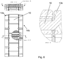
- the lateral links of the same pair are connected by a bar 16 defining an axis with reference to which a link in the central row 12 is movable.
- This link of the central row 12 is connected elastically by its flexible part to the bar 16.
- the assembly thus formed by the pair of lateral links 13a, 13b, by the bar 16 and by the element of the central row 12, is in one piece .
- the flexible connection portion of the link 10 of the central row 12 is a spiral strip 18 wound around the bar 16, and therefore made integrally with the bar 16.
- a preferred embodiment proposes to extend the one-piece construction.
- two consecutive bracelet links of the central row 12 are connected together by a pair formed by a first link 13a and a second link 13b of each lateral row 14a and 14b, respectively. More specifically, as mentioned above, the first 13a and second links 13b of a pair are connected by a first and a second bar 16. Each of these bars 16 is connected to one of the consecutive links of the central row 12, by a spiral strip 18.
- the spiral strips 18 are wound or unwound.
- the spiral bands 18 are wound when the bracelet is tightened, that is to say when the radius of curvature formed by the bracelet decreases, as if to adapt it to a smaller wrist .
- the spiral strips 18 define a stop when the turns are in contact with one another and resting on their respective bar 16, thus defining stop means, arranged to limit a relative movement of the links of the lateral row 14a, 14b relative to said bracelet link of the central row 12, in this case in the direction of the winding of the bracelet.
- the spiral bands 18 also define a stop limiting displacements resulting from a tensile force (T on the figure 2 ), in the longitudinal axis of the bracelet.
- T tensile force
- edges 20 of the links of the central row 12 arranged perpendicular to the main axis of the bracelet are adjusted with play, so as to allow relative movement between the links of the central row 12.
- the consecutive bracelet links of the central row 12, in particular the edges 20, are shaped so as to define means of stops, arranged to limit a relative movement of said adjacent links, in this case in the direction of the unwinding of the bracelet.
- a displacement causes an unwinding of the spiral, that is to say, with reference to the drawing, a displacement tending to open the bracelet or to enlarge its size relative to the wrist of a wearer.
- the underside of the central link defines a foot 22, intended to be in contact with the skin of the wearer of the bracelet.
- This foot 22 defines concave walls 24 serving as housing, at least partially, for the spiral strips 18 of the flexible portions.
- the foot 22 is intended to form a support on the arm of the wearer.
- each strand comprises, at one end, means for attaching to a watch case, and at another end, means for attaching to a clasp.
- a bar 16 connecting the links of a pair we can leave apparent a bar 16 connecting the links of a pair.
- the clasp or the box can then be provided with movable tongues, capable of cooperating with the bars 16, to grip them and be made integral therewith.
- the invention relates to a method for producing a bracelet or a bracelet element as proposed above, in which the monobloc piece is produced by 3D printing or by an additive manufacturing method.
- a main advantage of using additive manufacturing techniques is to allow great adaptation, or even custom manufacturing, in the factory or custom-made even in the shop.
- the parametrization / sizing step consists in defining the dimensions of the one-piece piece, taking into account the geometry of the bracelet and the dimensions of the wrist measured.
- the monobloc piece concerned here can be a bracelet element or several elements or the entire bracelet, except the attachment elements which should, if necessary, be added.
- the bracelet can be produced directly by an additive manufacturing technique.
- a surface treatment step called the finishing step, which can consist of polishing, chamfering, satin-finishing, or a combination of these operations.
- the additive manufacturing step can be carried out so that the one-piece part is obtained in a rigid state, that is to say without mobility between the various elements, which makes it possible to facilitate the operations of finish.
- This continuity zone can be ablated, by cutting out, or machining, in order to free the flexible parts and to confer mobility between the elements of the central row 12 and the links of the lateral rows 14a, 14b, respectively ( fig. 6 ).
- the method for producing this bracelet can also be adapted so that the bracelet is manufactured / printed, with a preform, in particular to possibly take account of the amplitudes of relative movement between the links.
- the bracelet may not be able to be laid flat, or in which the difference between its maximum “unwound” and “wound” positions is limited.
- We can then choose to make at least some of the consecutive links, which each define a main plane, so that these consecutive links define between their respective main planes, and on the side intended to be in contact with the arm of the wearer, an angle less than 180 °.
- each central link could include a flexible connection portion in the form of a spiral wound around a bar secured to the lateral portions of the neighboring link.
- a large number of variants are possible.
- each lateral link is made integral with the bar by means of a additional flexible connection portion, for example in the form of a spiral.
- provision could be made for two studs integral with the central link to fulfill the function of the bar 16, a lateral link being made integral with each stud by means of a flexible connection portion.
Landscapes
- Engineering & Computer Science (AREA)
- Manufacturing & Machinery (AREA)
- Chemical & Material Sciences (AREA)
- Materials Engineering (AREA)
- Adornments (AREA)
Claims (14)
- Gliederarmbandelement, welches wenigstens ein erstes und ein zweites Glied (10, 13a, 13b) umfasst, die untereinander verbunden sind und von denen jedes einen starren Basisabschnitt aufweist, wobei die starren Basisabschnitte durch wenigstens einen flexiblen Verbindungsabschnitt (18) miteinander verbunden sind,
dadurch gekennzeichnet, dass die starren Basisabschnitte und der flexible Verbindungsabschnitt zusammen ein einstückig ausgebildetes Teil definieren. - Armbandelement nach Anspruch 1, dadurch gekennzeichnet, dass der flexible Verbindungsabschnitt dafür ausgebildet ist, ein flexibles Gelenk zwischen dem ersten und dem zweiten Glied zu bilden.
- Armbandelement nach Anspruch 1 oder 2, dadurch gekennzeichnet, dass es wenigstens ein drittes Glied umfasst, das einen starren Basisabschnitt aufweist, der mit dem ersten Glied durch den flexiblen Verbindungsabschnitt und/oder einen zusätzlichen flexiblen Verbindungsabschnitt verbunden ist, wobei der starre Basisabschnitt des dritten Gliedes und gegebenenfalls der zusätzliche flexible Verbindungsabschnitt ebenfalls Teil des einstückig ausgebildeten Teils sind.
- Armbandelement nach Anspruch 3, dadurch gekennzeichnet, dass das erste, zweite und dritte Glied derart angeordnet sind, dass sich das zweite und dritte Glied beiderseits des ersten Gliedes befinden, wobei sie in Bezug auf dieses versetzt sind und wobei sie einander gegenüberliegen.
- Armband, welches mehrere Armbandelemente nach einem der Ansprüche 3 oder 4 aufweist, von denen die ersten Glieder eine mittlere Reihe (12) bilden, die zweiten Glieder eine erste seitliche Reihe (14a) bilden und die dritten Glieder eine zweite seitliche Reihe (14b) bilden, dadurch gekennzeichnet, dass zwei einander gegenüberliegende Glieder (13a, 13b), die sich in der ersten bzw. zweiten seitlichen Reihe (14a, 14b) befinden, durch einen Stab (16) verbunden sind, der eine Achse definiert, in Bezug auf die ein Glied der mittleren Reihe (12) beweglich ist, wobei das Glied der mittleren Reihe über seinen flexiblen Verbindungsabschnitt elastisch mit dem Stab (16) verbunden ist und mit dem Stab (16) und den beiden Gliedern der seitlichen Reihen (14a, 14b) eine einstückige Einheit bildet.
- Armband nach Anspruch 5, dadurch gekennzeichnet, dass der flexible Abschnitt ein spiralförmiges Band (18) umfasst, das um den Stab (16) herumgewickelt ist.
- Armband nach Anspruch 6, dadurch gekennzeichnet, dass die Glieder der mittleren Reihe (12) von wenigstens zwei aufeinander folgenden Armbandelementen durch ein erstes Glied (13a) und ein zweites Glied (13b) der jeweiligen seitlichen Reihe (14a, 14b), die einander gegenüberliegen, miteinander verbunden sind, wobei die Glieder der mittleren Reihe (12) derart ausgebildet sind, dass sie Anschlagmittel definieren, die dafür ausgelegt sind, die relative Verschiebung zwischen den aufeinander folgenden Armbandelementen zu begrenzen, wobei die relative Verschiebung eine Verformung des spiralförmigen Bandes (18) hervorruft.
- Armband nach einem der Ansprüche 5 oder 6, dadurch gekennzeichnet, dass wenigstens eines der Glieder der mittleren Reihe (12) derart ausgebildet ist, dass es Anschlagmittel definiert, die dafür ausgelegt sind, eine relative Verschiebung der benachbarten Glieder der ersten und der zweiten seitlichen Reihe (14a, 14b) in Bezug auf das Glied der mittleren Reihe (12) zu begrenzen, wobei die relative Verschiebung eine Verformung des spiralförmigen Bandes (18) hervorruft.
- Armband nach einem der Ansprüche 5 bis 8, welches zwei Streifen umfasst, wobei jeder Streifen an einem Ende Mittel zur Befestigung an einem Uhrengehäuse und an einem anderen Ende Mittel zur Befestigung an einem Verschluss umfasst.
- Armband nach einem der Ansprüche 5 bis 8, welches einen einzigen Streifen umfasst, wobei der Streifen an seinen Enden Mittel zur Befestigung an einem Uhrengehäuse umfasst und bei dem wenigstens eines seiner Enden über eine ohne Werkzeug lösbare Befestigung an dem Uhrengehäuse verfügt.
- Verfahren zur Herstellung eines Armbandelements nach einem der Ansprüche 1 bis 4 oder eines Armbands nach einem der Ansprüche 5 bis 10, dadurch gekennzeichnet, dass es einen Schritt der Herstellung des einstückigen Teils durch 3D-Druck oder durch ein Verfahren der additiven Fertigung umfasst.
- Herstellungsverfahren nach Anspruch 11, dadurch gekennzeichnet, dass es die folgenden Schritte umfasst:- Parametrierung / Bemessung des einstückigen Teils auf der Basis von Informationen, die mit den Abmessungen und/oder der Geometrie des Handgelenks eines Trägers zusammenhängen,- Herstellung des einstückigen Teils durch SD-Druck oder durch das Verfahren der additiven Fertigung.
- Verfahren zur Herstellung eines Armbands nach einem der Ansprüche 11 oder 12, welches die folgenden Schritte umfasst:- Erhalten des einstückigen Teils durch den Schritt des 3D-Drucks oder der additiven Fertigung, wobei das einstückige Teil wenigstens zwei starre Abschnitte aufweist, die untereinander einerseits durch einen flexiblen Verbindungsabschnitt und andererseits durch ein starres Verbindungselement, das jede relative Verschiebung zwischen den starren Abschnitten verhindert, verbunden sind,- Endbearbeitung der Oberfläche des einstückigen Teils,- Entfernen des starren Verbindungselements, um wenigstens einen Freiheitsgrad zwischen den starren Abschnitten des Armbands zu erzeugen.
- Herstellungsverfahren nach einem der Ansprüche 11 bis 13, wobei jedes Glied eine Hauptebene definiert, dadurch gekennzeichnet, dass wenigstens einige der aufeinander folgenden Glieder zwischen ihren jeweiligen Hauptebenen und auf der Seite, die dazu bestimmt ist, mit dem Arm des Trägers in Kontakt zu kommen, einen Winkel von weniger als 180° definieren.
Applications Claiming Priority (1)
| Application Number | Priority Date | Filing Date | Title |
|---|---|---|---|
| CH01087/17A CH714109A1 (fr) | 2017-09-01 | 2017-09-01 | Bracelet articulé. |
Publications (2)
| Publication Number | Publication Date |
|---|---|
| EP3449755A1 EP3449755A1 (de) | 2019-03-06 |
| EP3449755B1 true EP3449755B1 (de) | 2020-04-29 |
Family
ID=60009381
Family Applications (1)
| Application Number | Title | Priority Date | Filing Date |
|---|---|---|---|
| EP18190995.3A Active EP3449755B1 (de) | 2017-09-01 | 2018-08-27 | Armband mit gelenkgliedern |
Country Status (2)
| Country | Link |
|---|---|
| EP (1) | EP3449755B1 (de) |
| CH (1) | CH714109A1 (de) |
Families Citing this family (1)
| Publication number | Priority date | Publication date | Assignee | Title |
|---|---|---|---|---|
| CA3120648A1 (fr) * | 2018-11-26 | 2020-06-04 | Rolex Sa | Procede de configuration d'un bracelet de montre bracelet |
Family Cites Families (5)
| Publication number | Priority date | Publication date | Assignee | Title |
|---|---|---|---|---|
| US1440230A (en) * | 1922-06-27 | 1922-12-26 | Mestekin Bernard | Link for chain bracelets and detachable hinges for the same |
| BE830919A (fr) * | 1974-07-12 | 1975-11-03 | Bracelet de montre | |
| DK0921742T3 (da) * | 1996-08-29 | 2001-10-01 | Tag Heuer Sa | Urarmbånd med hængslede led og ur med et sådant armbånd |
| FR3002726B1 (fr) * | 2013-03-04 | 2016-01-01 | Samia Ferrad | Moyen de liaison amovible entre deux elements d'un article de bijouterie ou d'un accessoire de mode |
| CN105726035B (zh) * | 2016-02-02 | 2018-09-07 | 厦门精图信息技术有限公司 | 一种3d打印的可穿戴的活动监测装置 |
-
2017
- 2017-09-01 CH CH01087/17A patent/CH714109A1/fr unknown
-
2018
- 2018-08-27 EP EP18190995.3A patent/EP3449755B1/de active Active
Non-Patent Citations (1)
| Title |
|---|
| None * |
Also Published As
| Publication number | Publication date |
|---|---|
| EP3449755A1 (de) | 2019-03-06 |
| CH714109A1 (fr) | 2019-03-15 |
Similar Documents
| Publication | Publication Date | Title |
|---|---|---|
| EP2672337B1 (de) | Entfernbare klappbefestigung für armband | |
| EP2709482B1 (de) | Armband für uhren | |
| EP2720092B1 (de) | Befestigungssystem eines Armbands an ein Armbanduhrgehäuse | |
| EP1790247B1 (de) | Einrichtung zum Verstellen der Länge eines Armbandes, Armband mit einer solchen Einrichtung, und Uhr ausgerüstet mit einem solchen Armband | |
| EP2720093B1 (de) | Befestigungssystem eines Armbands an ein Armbanduhrgehäuse | |
| EP3338586B1 (de) | Armband für armbanduhr oder schmuckstück | |
| EP1566110A1 (de) | Armband aus starren Gliedern auf einer flexiblen Seele | |
| EP3420839B1 (de) | Verschluss für armbanduhr | |
| WO1998044379A1 (fr) | Charniere extensible extra-plate | |
| EP0661938B1 (de) | Faltverschluss für armbänder | |
| EP3449755B1 (de) | Armband mit gelenkgliedern | |
| EP1731052B1 (de) | Hals- oder Armband mit regelmässig angeordneten Gliedern auf einem flexiblen Band | |
| EP1731053B1 (de) | Nichtausdehnbares Gliedarmband | |
| EP0780742B1 (de) | Bewegliches Rolladensystem für eine Uhr | |
| EP4159080B1 (de) | Verstellbarer armbandverschluss | |
| EP3941300B1 (de) | Schnalle für ein uhrenband oder armband | |
| EP0196996B1 (de) | Gliederarmband mit Gelenkverbindung | |
| EP0006664B1 (de) | Ein aus starren, direkt ineinandergefügten Gliedern bestehendes Armband | |
| EP4609746A1 (de) | Dehnbarer dekorativer artikel | |
| EP1566111B1 (de) | Armband aus starren Gliedern auf einer flexiblen Seele | |
| EP3777599B1 (de) | Elastisches gelenk für uhrzusammenbau | |
| EP3219220A1 (de) | Einstellvorrichtung für armband | |
| CH713613A2 (fr) | Fermoir à boucle déployante. | |
| WO1998018360A1 (fr) | Bracelet rigide notamment pour montre | |
| EP2745726A1 (de) | Schmuckelement eines Uhrenarmbands |
Legal Events
| Date | Code | Title | Description |
|---|---|---|---|
| PUAI | Public reference made under article 153(3) epc to a published international application that has entered the european phase |
Free format text: ORIGINAL CODE: 0009012 |
|
| STAA | Information on the status of an ep patent application or granted ep patent |
Free format text: STATUS: THE APPLICATION HAS BEEN PUBLISHED |
|
| AK | Designated contracting states |
Kind code of ref document: A1 Designated state(s): AL AT BE BG CH CY CZ DE DK EE ES FI FR GB GR HR HU IE IS IT LI LT LU LV MC MK MT NL NO PL PT RO RS SE SI SK SM TR |
|
| AX | Request for extension of the european patent |
Extension state: BA ME |
|
| STAA | Information on the status of an ep patent application or granted ep patent |
Free format text: STATUS: REQUEST FOR EXAMINATION WAS MADE |
|
| 17P | Request for examination filed |
Effective date: 20190614 |
|
| RBV | Designated contracting states (corrected) |
Designated state(s): AL AT BE BG CH CY CZ DE DK EE ES FI FR GB GR HR HU IE IS IT LI LT LU LV MC MK MT NL NO PL PT RO RS SE SI SK SM TR |
|
| GRAP | Despatch of communication of intention to grant a patent |
Free format text: ORIGINAL CODE: EPIDOSNIGR1 |
|
| STAA | Information on the status of an ep patent application or granted ep patent |
Free format text: STATUS: GRANT OF PATENT IS INTENDED |
|
| RIC1 | Information provided on ipc code assigned before grant |
Ipc: A44C 27/00 20060101ALI20190923BHEP Ipc: A44C 5/10 20060101AFI20190923BHEP Ipc: B29C 64/00 20170101ALI20190923BHEP Ipc: B33Y 80/00 20150101ALI20190923BHEP |
|
| INTG | Intention to grant announced |
Effective date: 20191024 |
|
| GRAS | Grant fee paid |
Free format text: ORIGINAL CODE: EPIDOSNIGR3 |
|
| GRAJ | Information related to disapproval of communication of intention to grant by the applicant or resumption of examination proceedings by the epo deleted |
Free format text: ORIGINAL CODE: EPIDOSDIGR1 |
|
| GRAL | Information related to payment of fee for publishing/printing deleted |
Free format text: ORIGINAL CODE: EPIDOSDIGR3 |
|
| STAA | Information on the status of an ep patent application or granted ep patent |
Free format text: STATUS: REQUEST FOR EXAMINATION WAS MADE |
|
| GRAR | Information related to intention to grant a patent recorded |
Free format text: ORIGINAL CODE: EPIDOSNIGR71 |
|
| STAA | Information on the status of an ep patent application or granted ep patent |
Free format text: STATUS: GRANT OF PATENT IS INTENDED |
|
| INTC | Intention to grant announced (deleted) | ||
| GRAA | (expected) grant |
Free format text: ORIGINAL CODE: 0009210 |
|
| STAA | Information on the status of an ep patent application or granted ep patent |
Free format text: STATUS: THE PATENT HAS BEEN GRANTED |
|
| INTG | Intention to grant announced |
Effective date: 20200319 |
|
| AK | Designated contracting states |
Kind code of ref document: B1 Designated state(s): AL AT BE BG CH CY CZ DE DK EE ES FI FR GB GR HR HU IE IS IT LI LT LU LV MC MK MT NL NO PL PT RO RS SE SI SK SM TR |
|
| REG | Reference to a national code |
Ref country code: GB Ref legal event code: FG4D Free format text: NOT ENGLISH |
|
| REG | Reference to a national code |
Ref country code: CH Ref legal event code: EP |
|
| REG | Reference to a national code |
Ref country code: DE Ref legal event code: R096 Ref document number: 602018004152 Country of ref document: DE |
|
| REG | Reference to a national code |
Ref country code: AT Ref legal event code: REF Ref document number: 1262009 Country of ref document: AT Kind code of ref document: T Effective date: 20200515 |
|
| REG | Reference to a national code |
Ref country code: IE Ref legal event code: FG4D Free format text: LANGUAGE OF EP DOCUMENT: FRENCH |
|
| REG | Reference to a national code |
Ref country code: CH Ref legal event code: NV Representative=s name: E-PATENT S.A., CH |
|
| REG | Reference to a national code |
Ref country code: NL Ref legal event code: MP Effective date: 20200429 |
|
| REG | Reference to a national code |
Ref country code: LT Ref legal event code: MG4D |
|
| PG25 | Lapsed in a contracting state [announced via postgrant information from national office to epo] |
Ref country code: GR Free format text: LAPSE BECAUSE OF FAILURE TO SUBMIT A TRANSLATION OF THE DESCRIPTION OR TO PAY THE FEE WITHIN THE PRESCRIBED TIME-LIMIT Effective date: 20200730 Ref country code: SE Free format text: LAPSE BECAUSE OF FAILURE TO SUBMIT A TRANSLATION OF THE DESCRIPTION OR TO PAY THE FEE WITHIN THE PRESCRIBED TIME-LIMIT Effective date: 20200429 Ref country code: PT Free format text: LAPSE BECAUSE OF FAILURE TO SUBMIT A TRANSLATION OF THE DESCRIPTION OR TO PAY THE FEE WITHIN THE PRESCRIBED TIME-LIMIT Effective date: 20200831 Ref country code: LT Free format text: LAPSE BECAUSE OF FAILURE TO SUBMIT A TRANSLATION OF THE DESCRIPTION OR TO PAY THE FEE WITHIN THE PRESCRIBED TIME-LIMIT Effective date: 20200429 Ref country code: FI Free format text: LAPSE BECAUSE OF FAILURE TO SUBMIT A TRANSLATION OF THE DESCRIPTION OR TO PAY THE FEE WITHIN THE PRESCRIBED TIME-LIMIT Effective date: 20200429 Ref country code: IS Free format text: LAPSE BECAUSE OF FAILURE TO SUBMIT A TRANSLATION OF THE DESCRIPTION OR TO PAY THE FEE WITHIN THE PRESCRIBED TIME-LIMIT Effective date: 20200829 Ref country code: NO Free format text: LAPSE BECAUSE OF FAILURE TO SUBMIT A TRANSLATION OF THE DESCRIPTION OR TO PAY THE FEE WITHIN THE PRESCRIBED TIME-LIMIT Effective date: 20200729 |
|
| REG | Reference to a national code |
Ref country code: AT Ref legal event code: MK05 Ref document number: 1262009 Country of ref document: AT Kind code of ref document: T Effective date: 20200429 |
|
| PG25 | Lapsed in a contracting state [announced via postgrant information from national office to epo] |
Ref country code: LV Free format text: LAPSE BECAUSE OF FAILURE TO SUBMIT A TRANSLATION OF THE DESCRIPTION OR TO PAY THE FEE WITHIN THE PRESCRIBED TIME-LIMIT Effective date: 20200429 Ref country code: HR Free format text: LAPSE BECAUSE OF FAILURE TO SUBMIT A TRANSLATION OF THE DESCRIPTION OR TO PAY THE FEE WITHIN THE PRESCRIBED TIME-LIMIT Effective date: 20200429 Ref country code: BG Free format text: LAPSE BECAUSE OF FAILURE TO SUBMIT A TRANSLATION OF THE DESCRIPTION OR TO PAY THE FEE WITHIN THE PRESCRIBED TIME-LIMIT Effective date: 20200729 Ref country code: RS Free format text: LAPSE BECAUSE OF FAILURE TO SUBMIT A TRANSLATION OF THE DESCRIPTION OR TO PAY THE FEE WITHIN THE PRESCRIBED TIME-LIMIT Effective date: 20200429 |
|
| PG25 | Lapsed in a contracting state [announced via postgrant information from national office to epo] |
Ref country code: NL Free format text: LAPSE BECAUSE OF FAILURE TO SUBMIT A TRANSLATION OF THE DESCRIPTION OR TO PAY THE FEE WITHIN THE PRESCRIBED TIME-LIMIT Effective date: 20200429 Ref country code: AL Free format text: LAPSE BECAUSE OF FAILURE TO SUBMIT A TRANSLATION OF THE DESCRIPTION OR TO PAY THE FEE WITHIN THE PRESCRIBED TIME-LIMIT Effective date: 20200429 |
|
| PG25 | Lapsed in a contracting state [announced via postgrant information from national office to epo] |
Ref country code: RO Free format text: LAPSE BECAUSE OF FAILURE TO SUBMIT A TRANSLATION OF THE DESCRIPTION OR TO PAY THE FEE WITHIN THE PRESCRIBED TIME-LIMIT Effective date: 20200429 Ref country code: CZ Free format text: LAPSE BECAUSE OF FAILURE TO SUBMIT A TRANSLATION OF THE DESCRIPTION OR TO PAY THE FEE WITHIN THE PRESCRIBED TIME-LIMIT Effective date: 20200429 Ref country code: ES Free format text: LAPSE BECAUSE OF FAILURE TO SUBMIT A TRANSLATION OF THE DESCRIPTION OR TO PAY THE FEE WITHIN THE PRESCRIBED TIME-LIMIT Effective date: 20200429 Ref country code: EE Free format text: LAPSE BECAUSE OF FAILURE TO SUBMIT A TRANSLATION OF THE DESCRIPTION OR TO PAY THE FEE WITHIN THE PRESCRIBED TIME-LIMIT Effective date: 20200429 Ref country code: IT Free format text: LAPSE BECAUSE OF FAILURE TO SUBMIT A TRANSLATION OF THE DESCRIPTION OR TO PAY THE FEE WITHIN THE PRESCRIBED TIME-LIMIT Effective date: 20200429 Ref country code: SM Free format text: LAPSE BECAUSE OF FAILURE TO SUBMIT A TRANSLATION OF THE DESCRIPTION OR TO PAY THE FEE WITHIN THE PRESCRIBED TIME-LIMIT Effective date: 20200429 Ref country code: AT Free format text: LAPSE BECAUSE OF FAILURE TO SUBMIT A TRANSLATION OF THE DESCRIPTION OR TO PAY THE FEE WITHIN THE PRESCRIBED TIME-LIMIT Effective date: 20200429 Ref country code: DK Free format text: LAPSE BECAUSE OF FAILURE TO SUBMIT A TRANSLATION OF THE DESCRIPTION OR TO PAY THE FEE WITHIN THE PRESCRIBED TIME-LIMIT Effective date: 20200429 |
|
| REG | Reference to a national code |
Ref country code: DE Ref legal event code: R097 Ref document number: 602018004152 Country of ref document: DE |
|
| PG25 | Lapsed in a contracting state [announced via postgrant information from national office to epo] |
Ref country code: PL Free format text: LAPSE BECAUSE OF FAILURE TO SUBMIT A TRANSLATION OF THE DESCRIPTION OR TO PAY THE FEE WITHIN THE PRESCRIBED TIME-LIMIT Effective date: 20200429 Ref country code: SK Free format text: LAPSE BECAUSE OF FAILURE TO SUBMIT A TRANSLATION OF THE DESCRIPTION OR TO PAY THE FEE WITHIN THE PRESCRIBED TIME-LIMIT Effective date: 20200429 |
|
| PLBE | No opposition filed within time limit |
Free format text: ORIGINAL CODE: 0009261 |
|
| STAA | Information on the status of an ep patent application or granted ep patent |
Free format text: STATUS: NO OPPOSITION FILED WITHIN TIME LIMIT |
|
| PG25 | Lapsed in a contracting state [announced via postgrant information from national office to epo] |
Ref country code: MC Free format text: LAPSE BECAUSE OF FAILURE TO SUBMIT A TRANSLATION OF THE DESCRIPTION OR TO PAY THE FEE WITHIN THE PRESCRIBED TIME-LIMIT Effective date: 20200429 |
|
| 26N | No opposition filed |
Effective date: 20210201 |
|
| PG25 | Lapsed in a contracting state [announced via postgrant information from national office to epo] |
Ref country code: LU Free format text: LAPSE BECAUSE OF NON-PAYMENT OF DUE FEES Effective date: 20200827 |
|
| REG | Reference to a national code |
Ref country code: BE Ref legal event code: MM Effective date: 20200831 |
|
| PG25 | Lapsed in a contracting state [announced via postgrant information from national office to epo] |
Ref country code: SI Free format text: LAPSE BECAUSE OF FAILURE TO SUBMIT A TRANSLATION OF THE DESCRIPTION OR TO PAY THE FEE WITHIN THE PRESCRIBED TIME-LIMIT Effective date: 20200429 |
|
| PG25 | Lapsed in a contracting state [announced via postgrant information from national office to epo] |
Ref country code: BE Free format text: LAPSE BECAUSE OF NON-PAYMENT OF DUE FEES Effective date: 20200831 Ref country code: IE Free format text: LAPSE BECAUSE OF NON-PAYMENT OF DUE FEES Effective date: 20200827 |
|
| PG25 | Lapsed in a contracting state [announced via postgrant information from national office to epo] |
Ref country code: TR Free format text: LAPSE BECAUSE OF FAILURE TO SUBMIT A TRANSLATION OF THE DESCRIPTION OR TO PAY THE FEE WITHIN THE PRESCRIBED TIME-LIMIT Effective date: 20200429 Ref country code: MT Free format text: LAPSE BECAUSE OF FAILURE TO SUBMIT A TRANSLATION OF THE DESCRIPTION OR TO PAY THE FEE WITHIN THE PRESCRIBED TIME-LIMIT Effective date: 20200429 Ref country code: CY Free format text: LAPSE BECAUSE OF FAILURE TO SUBMIT A TRANSLATION OF THE DESCRIPTION OR TO PAY THE FEE WITHIN THE PRESCRIBED TIME-LIMIT Effective date: 20200429 |
|
| PG25 | Lapsed in a contracting state [announced via postgrant information from national office to epo] |
Ref country code: MK Free format text: LAPSE BECAUSE OF FAILURE TO SUBMIT A TRANSLATION OF THE DESCRIPTION OR TO PAY THE FEE WITHIN THE PRESCRIBED TIME-LIMIT Effective date: 20200429 |
|
| PGFP | Annual fee paid to national office [announced via postgrant information from national office to epo] |
Ref country code: DE Payment date: 20250820 Year of fee payment: 8 |
|
| PGFP | Annual fee paid to national office [announced via postgrant information from national office to epo] |
Ref country code: GB Payment date: 20250821 Year of fee payment: 8 |
|
| PGFP | Annual fee paid to national office [announced via postgrant information from national office to epo] |
Ref country code: FR Payment date: 20250828 Year of fee payment: 8 |
|
| PGFP | Annual fee paid to national office [announced via postgrant information from national office to epo] |
Ref country code: CH Payment date: 20250901 Year of fee payment: 8 |