EP3449762B1 - Pulverausgabebehälter - Google Patents
Pulverausgabebehälter Download PDFInfo
- Publication number
- EP3449762B1 EP3449762B1 EP16820146.5A EP16820146A EP3449762B1 EP 3449762 B1 EP3449762 B1 EP 3449762B1 EP 16820146 A EP16820146 A EP 16820146A EP 3449762 B1 EP3449762 B1 EP 3449762B1
- Authority
- EP
- European Patent Office
- Prior art keywords
- powder
- button part
- container
- stem
- discharging
- Prior art date
- Legal status (The legal status is an assumption and is not a legal conclusion. Google has not performed a legal analysis and makes no representation as to the accuracy of the status listed.)
- Active
Links
Images


Classifications
-
- B—PERFORMING OPERATIONS; TRANSPORTING
- B05—SPRAYING OR ATOMISING IN GENERAL; APPLYING FLUENT MATERIALS TO SURFACES, IN GENERAL
- B05B—SPRAYING APPARATUS; ATOMISING APPARATUS; NOZZLES
- B05B11/00—Single-unit hand-held apparatus in which flow of contents is produced by the muscular force of the operator at the moment of use
- B05B11/01—Single-unit hand-held apparatus in which flow of contents is produced by the muscular force of the operator at the moment of use characterised by the means producing the flow
- B05B11/06—Gas or vapour producing the flow, e.g. from a compressible bulb or air pump
- B05B11/062—Gas or vapour producing the flow, e.g. from a compressible bulb or air pump designed for spraying particulate material
-
- A—HUMAN NECESSITIES
- A45—HAND OR TRAVELLING ARTICLES
- A45D—HAIRDRESSING OR SHAVING EQUIPMENT; EQUIPMENT FOR COSMETICS OR COSMETIC TREATMENTS, e.g. FOR MANICURING OR PEDICURING
- A45D33/00—Containers or accessories specially adapted for handling powdery toiletry or cosmetic substances
- A45D33/02—Containers or accessories specially adapted for handling powdery toiletry or cosmetic substances with dispensing means, e.g. sprinkling means
-
- A—HUMAN NECESSITIES
- A45—HAND OR TRAVELLING ARTICLES
- A45D—HAIRDRESSING OR SHAVING EQUIPMENT; EQUIPMENT FOR COSMETICS OR COSMETIC TREATMENTS, e.g. FOR MANICURING OR PEDICURING
- A45D33/00—Containers or accessories specially adapted for handling powdery toiletry or cosmetic substances
- A45D33/02—Containers or accessories specially adapted for handling powdery toiletry or cosmetic substances with dispensing means, e.g. sprinkling means
- A45D33/08—Containers or accessories specially adapted for handling powdery toiletry or cosmetic substances with dispensing means, e.g. sprinkling means operated by rotary vanes
-
- B—PERFORMING OPERATIONS; TRANSPORTING
- B05—SPRAYING OR ATOMISING IN GENERAL; APPLYING FLUENT MATERIALS TO SURFACES, IN GENERAL
- B05B—SPRAYING APPARATUS; ATOMISING APPARATUS; NOZZLES
- B05B11/00—Single-unit hand-held apparatus in which flow of contents is produced by the muscular force of the operator at the moment of use
- B05B11/0005—Components or details
- B05B11/0027—Means for neutralising the actuation of the sprayer ; Means for preventing access to the sprayer actuation means
- B05B11/0029—Valves not actuated by pressure
-
- B—PERFORMING OPERATIONS; TRANSPORTING
- B05—SPRAYING OR ATOMISING IN GENERAL; APPLYING FLUENT MATERIALS TO SURFACES, IN GENERAL
- B05B—SPRAYING APPARATUS; ATOMISING APPARATUS; NOZZLES
- B05B11/00—Single-unit hand-held apparatus in which flow of contents is produced by the muscular force of the operator at the moment of use
- B05B11/0005—Components or details
- B05B11/0027—Means for neutralising the actuation of the sprayer ; Means for preventing access to the sprayer actuation means
- B05B11/0032—Manually actuated means located downstream the discharge nozzle for closing or covering it, e.g. shutters
-
- B—PERFORMING OPERATIONS; TRANSPORTING
- B05—SPRAYING OR ATOMISING IN GENERAL; APPLYING FLUENT MATERIALS TO SURFACES, IN GENERAL
- B05B—SPRAYING APPARATUS; ATOMISING APPARATUS; NOZZLES
- B05B11/00—Single-unit hand-held apparatus in which flow of contents is produced by the muscular force of the operator at the moment of use
- B05B11/01—Single-unit hand-held apparatus in which flow of contents is produced by the muscular force of the operator at the moment of use characterised by the means producing the flow
- B05B11/10—Pump arrangements for transferring the contents from the container to a pump chamber by a sucking effect and forcing the contents out through the dispensing nozzle
- B05B11/1042—Components or details
- B05B11/1059—Means for locking a pump or its actuation means in a fixed position
-
- B—PERFORMING OPERATIONS; TRANSPORTING
- B65—CONVEYING; PACKING; STORING; HANDLING THIN OR FILAMENTARY MATERIAL
- B65D—CONTAINERS FOR STORAGE OR TRANSPORT OF ARTICLES OR MATERIALS, e.g. BAGS, BARRELS, BOTTLES, BOXES, CANS, CARTONS, CRATES, DRUMS, JARS, TANKS, HOPPERS, FORWARDING CONTAINERS; ACCESSORIES, CLOSURES, OR FITTINGS THEREFOR; PACKAGING ELEMENTS; PACKAGES
- B65D47/00—Closures with filling and discharging, or with discharging, devices
-
- B—PERFORMING OPERATIONS; TRANSPORTING
- B65—CONVEYING; PACKING; STORING; HANDLING THIN OR FILAMENTARY MATERIAL
- B65D—CONTAINERS FOR STORAGE OR TRANSPORT OF ARTICLES OR MATERIALS, e.g. BAGS, BARRELS, BOTTLES, BOXES, CANS, CARTONS, CRATES, DRUMS, JARS, TANKS, HOPPERS, FORWARDING CONTAINERS; ACCESSORIES, CLOSURES, OR FITTINGS THEREFOR; PACKAGING ELEMENTS; PACKAGES
- B65D83/00—Containers or packages with special means for dispensing contents
- B65D83/06—Containers or packages with special means for dispensing contents for dispensing powdered or granular material
-
- B—PERFORMING OPERATIONS; TRANSPORTING
- B65—CONVEYING; PACKING; STORING; HANDLING THIN OR FILAMENTARY MATERIAL
- B65D—CONTAINERS FOR STORAGE OR TRANSPORT OF ARTICLES OR MATERIALS, e.g. BAGS, BARRELS, BOTTLES, BOXES, CANS, CARTONS, CRATES, DRUMS, JARS, TANKS, HOPPERS, FORWARDING CONTAINERS; ACCESSORIES, CLOSURES, OR FITTINGS THEREFOR; PACKAGING ELEMENTS; PACKAGES
- B65D83/00—Containers or packages with special means for dispensing contents
- B65D83/76—Containers or packages with special means for dispensing contents for dispensing fluent contents by means of a piston
-
- A—HUMAN NECESSITIES
- A45—HAND OR TRAVELLING ARTICLES
- A45D—HAIRDRESSING OR SHAVING EQUIPMENT; EQUIPMENT FOR COSMETICS OR COSMETIC TREATMENTS, e.g. FOR MANICURING OR PEDICURING
- A45D33/00—Containers or accessories specially adapted for handling powdery toiletry or cosmetic substances
- A45D2033/001—Accessories
Definitions
- the present invention disclosed herein relates to a container for discharging powder, in particular, a container for discharging powder having a structure wherein a discharging hole of a button part and a connecting hole of a stem are connected or dislocated according to rotation directions, and an opening/closing member is inserted into the stem inside the button part and ascends/descends according to a rotation of the button part, thereby opening/closing a movement hole of the stem, such that it will solve inconvenience problems such as having to attach/detach the opening/closing member whenever using as well as prevent a risk of losing the opening/closing member, thereby providing user convenience.
- powder has its good wearability when applied on skin, and has its high water-repellency, such that power is widely being used because a user feels fresh on the skin and gets her makeup to look natural.
- the above registered patent is to provide a space wherein powder is filled therein, comprising a container body (10) having an upper surface opened and a bottom surface with an air inlet hole(10h); a pumping means (30) having a diaphragm (31), which is a contractible element made of elastic material with a cylindrical shape such that a rim of a lower portion can be folded into a rim of a bottom surface of the container body (10), absorbing air from the outside by a pumping operation and discharging the air into the space wherein the powder is filled outwardly through an air discharging hole (31h) formed at a center thereof, and an opening/closing button (35) which is disposed at an upper center portion of the diaphragm (31) and controls opening/closing of the air discharging hole (31h); a fixing plate (40) configured to be able to ascend/descend but not to be rotated in a state that an outer circumferential surface is closely contacted to an inner wall at an upper side of the pump
- the registered patent above has a configuration that powder comes to be discharged and to be applied on the puff (60) when an operation plate is tapped lightly with a puff (60) or pressurized in a state of a cap (20) being opened.
- a user should hold the puff (60) with one hand and then pressurize an operational plate (50) while holding the container body (10) with the other hand, thereby resulting in user inconvenience.
- the patent document 2 includes: a container body where powder is stored; a button part which is disposed at an upper portion of the container body and ascends/descends according to a user's pressurization, comprising, at one side thereof, a discharging hole such that the power can be discharged; and a stem which is coupled to a lower portion of the button part and moves along according to the movement of the button part, comprising a powder moving passage where powder moves and an air moving passage where air moves, separately installed at an inner side thereof.
- the patent document 2 discloses a structure wherein powder is easily sprayed onto a user's skin to be used when the button part is pressed.
- an opening/closing member which opens/closes the discharging hole is configured to have to be attached/detached to the button part, there arises not only a risk of losing the opening/closing member but also a problem that the power may be leaked through the discharging hole in case the container is shaken or dropped in a state of the discharging hole not being closed by the opening/closing member.
- the opening/closing member should be detached from the button part before using and be coupled to the button part after using, thus leading to user inconvenience.
- the present invention is devised to solve such problems described in the above, and the objective thereof is to provide a container for discharging powder having a structure wherein a discharging hole of a button part and a connecting hole of a stem are connected or dislocated according to rotation directions, and an opening/closing member is inserted into the stem inside the button part and ascends/descends according to rotation of the button part, and thereby opens/closes a movement hole of the stem, such that it will solve inconvenience problems such as attaching/detaching the opening/closing member whenever using and prevent a risk of losing the opening/closing member, thereby providing user convenience.
- a container for discharging powder is characterized to include: a container body storing powder therein; a button part rotatably disposed at an upper portion of the container body, ascending/descending according to the presence or absence of a user's pressurizing, and comprising a discharging hole at one side thereof; a stem disposed at an inner side of the button part and ascending/descending along with the button part, further comprising a movement hole at an upper portion thereof such that powder can move by control of the button part, and a connecting hole at a side thereof which is connected with the discharging hole such that the powder moving through the movement hole can be discharged through the discharging hole; a content movement part coupled at an inner side of the stem, separately comprising a powder moving passage where powder moves and an air moving passage where air moves; and an opening/closing member inserted to an upper portion of the stem, opening the movement hole as ascending when the button part rotates to one side direction and closing the movement hole as
- the inner pressure of the container body changes according to the pressurization of the button part, and powder and air move into an interior of the content movement part respectively through the powder moving passage and the air moving passage, and then the powder is sprayed through the discharging hole by air pressure.
- the container is characterized to further include a support body which is coupled to an upper portion of the container body, forming an extension part which extends to a lower part thereof so as to encase an upper inner circumferential surface of the container body at an upper inner side thereof.
- the container is characterized to further include a piston, at a lower portion of the stem, which moves along according to the ascent/descent of the stem, and gets closely contacted to inner circumferential surface of the extension part so as to change an inner pressure of the container body.
- the container is characterized to further include a protrusion part which is formed at a lower end of the stem, and comprises a spiral guide groove at both sides of an outer circumferential thereof so as to guide the ascent/descent of the ascending/descending member.
- the container is characterized to further include a guide tube which guides the ascent/descent of the ascending/descending member at an inner upper side of the button part, and a vertical guide groove which guides the vertical movement of the ascending/descending member at both sides of the guide tube.
- the ascending/descending member includes a first sealing part which is contacted to an inner circumferential surface of the stem to close the movement hole in a state of the ascending/descending member being lowered, and is separated from the inner circumferential surface to open the movement hole in a state of the ascending/descending member being raised up;
- a second sealing part which is closely contacted to an upper inner circumferential surface of the stem so that powder, which is supposed to move through the movement hole, is prevented from moving to an upper part of the stem not to the connecting hole and thus from being leaked; and a guide protrusion which is inserted to the vertical guide groove and the spiral guide groove, moving along the vertical guide groove and the spiral guide groove and guiding the ascent/descent of the ascending/descending member.
- the container is characterized to further include a rotation preventing protrusion, which is longitudinally formed so that the stem can be prevented from being rotated when the button part rotates, at an outer circumferential surface of the stem, and a rotation preventing groove, where the rotation preventing protrusion is inserted, at an inner circumferential surface of the support body.
- the container is characterized in that a pumping guide groove, which forms a space so that the button part can be able to ascend/descend, is equipped at both sides of an upper outer circumferential surface, and a pumping preventing protrusion which prevents the button part from moving downwards.
- the container is characterized in that a pumping guide protrusion, installed at an inner circumferential surface, is placed directly above the pumping guide groove and ascends/descends along the pumping guide groove when the button part rotates to one side direction.
- the pumping guide protrusion is placed directly above the pumping preventing protrusion and prevents the button part from descending when the button part rotates to the other side direction.
- the container is characterized in that an air compressing hole having a smaller diameter than that of the air moving passage is installed at an end of the air moving passage of the content movement part so as to compress and spray air therein.
- the container is characterized in that at a lower portion of the powder moving passage is installed a powder absorbing tube which moves the powder stored in the container body to the powder movement tube, wherein the powder absorbing tube moves upwards/downwards according to the pressurization of the button part and stirs the powder stored in the container body.
- a container for discharging powder is configured in a way that a discharging hole of a button part and a connecting hole of a stem are connected or dislocated according to rotation directions, and an opening/closing member inserted into the stem inside the button part ascends/descends according to a rotation of the button part and thereby opens/closes a movement hole of the stem, such that it will solve inconvenience problems such as attaching/detaching the opening/closing member whenever using as well as preventing a risk of losing the opening/closing member, thereby providing user convenience.
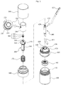
- FIG. 1 is an exploded perspective view illustrating a configuration of a container for discharging powder according to an exemplary embodiment of the present invention.
- FIG. 2 is a combined perspective view illustrating a configuration of the container for discharging powder according to an exemplary embodiment of the present invention.
- FIG. 3 is a combined cross-sectional view illustrating a configuration of the container for discharging powder according to an exemplary embodiment of the present invention.
- FIG. 4 is an explanatory drawing illustrating a position of a pumping guide protrusion depending on the rotation of a button part of the container for discharging powder according to an exemplary embodiment of the present invention.
- FIG. 5 is an explanatory drawing illustrating coupling state of a rotation preventing protrusion of a stem and a rotation preventing groove of a support body of the container for discharging powder according to an exemplary embodiment of the present invention.
- the container for discharging powder includes a container body 100, a button part 200, a stem 300, a content movement part 400 and an opening/closing member 500.
- the container body 100 containing powder comprises a discharging outlet 110 at an upper portion thereof such that the powder contained therein can be discharged.
- a support body 600 which is coupled to the discharging outlet 110 and closes an upper end of the discharging outlet 110.
- a support body 600 which is coupled to the discharging outlet 110 and closes an upper end of the discharging outlet 110.
- an extension part 610 which extends to a lower portion thereof so as to encase an upper inner circumferential surface of the container body 100
- a piston 700 which ascends/descends in a state of being tightly contacted to an inner circumferential surface of the extending part 610 and thereby changes the inner pressure of the container body 100.
- a pumping guide groove 620 which forms a space such that a button part 200 can ascends/descends and a pumping preventing protrusion 620 which prevents a downward movement of the button part 200. It is preferred to install a fixing protrusion 640, at the pumping guide groove 620 and the pumping preventing protrusion 630, which fixes a pumping guide protrusion 230 of the button part 200, so as to prevent the button part 200 from randomly rotating in a state that the button part 200 completes its rotation either to one side direction or to the other direction.
- a rotation preventing groove 650 where a rotation preventing protrusion 340 of the stem 300 so as to prevent the stem 300 from rotating along by the rotation of the button part 200.
- a spring support part 660 so as to support a spring (S) which restores the button part 200 by providing an elastic force to the stem 300.
- a shoulder part 800 is coupled at an upper portion of the container body 100, encasing the support body 600, wherein the shoulder part 800 forms a space where a button part to be described later is inserted to ascend/descend, and an over cap 900 is coupled at an outer side of the shoulder part 800, encasing the button part 200, to prevent a malfunction of the button part 200.
- the button part 200 which is rotatably coupled to a stem 300 at an upper portion of the container body 100, ascends/descends according to a user's pressurization and delivers the pressure to the stem 300, comprising a discharging hole 210 at one side thereof such that powder can be discharged.
- a guide tube 220 which guides the ascent/descent of an ascending/descending member 500, wherein at both sides of the guide tube 220 is formed a vertical guide groove 221 where a guide protrusion 530 of the ascending/descending member 500 is inserted to guide the vertical movement of the opening/closing member 500.
- a pumping guide protrusion 230 which controls the ascending/descending movement of the button part 200, wherein the pumping guide protrusion 230 is placed directly above the pumping preventing protrusion 630 of the support body 600 normally when in in use, and prevents the button part 200 from descending. Meanwhile, when the button part 200 rotates to one side direction for using, the pumping guide protrusion 230 gets out of the pumping preventing protrusion 630, then is placed directly above the pumping guide groove 620, and moves along the pumping guide grooves 620, thereby enabling the button part 200 to ascend/descend.
- a spring which provides elastic force to an upward direction when a user releases pressurizing the button part 200.
- the spring is installed between a stem 300 to be described later and a spring support part 660 of the support body 600, and provides an elastic force to the stem 300, thereby enabling the button part 200 to be restored.
- the stem 300 is coupled to a lower portion of the button part 200 and moves along as the button part 200 moves, wherein a movement hole 310 is formed at an inner side thereof such that powder can move toward a discharging hole 210 by controlling the button part 200, and at a side thereof is formed a connecting hole 320 which is connected with the discharging hole 210 such that the powder moving through the movement hole 310 can be discharged through the discharging hole 210.
- a piston 700 which is closely contacted to an inner circumferential surface of the extension part 610 so as to change an inner pressure of the container body 100 as moving along with the ascent/descent of the stem 300.
- the piston 700 ascends/descends in a state of being closely contacted to an inner circumferential surface of the extension part 610 according to whether or not the piston 700 pressurizes the button part 200, and thus changes an inner pressure of the container body 100, such that powder and air move to an upper portion through a powder movement passage 410 of the content movement part 400 and an air movement passage, and thereby are discharged through the discharging hole 210 of the button part 200.
- a protrusion part 330 which has a spiral guide groove 331 formed at both sides of an outer circumferential surface thereof so as to guide the ascent/descent of the opening/closing member 500, wherein a guide protrusion 530 of the opening/closing member 500 moves along the spiral guide groove 331 when the button part 200 rotates to one side direction or to the other direction, thereby leading to ascending/descending of the opening/closing member 500.
- a rotation preventing protrusion 340 which is inserted into a rotation preventing groove 650 of the support body 600 in order to prevent the stem 300 from rotating when the button part 200 rotates.
- the content movement tube 400 is coupled to an inner side of the stem 300 and forms a space where powder and air move.
- a powder moving passage 410 where powder moves and an air moving passage 420 where air moves are separately formed at an inner side of the content movement part 400.
- the present invention is characterized in that at an end of the air moving passage 420 is formed an air compressing hole 421 which has a smaller diameter than that of the air moving passage 420, wherein the air moving through the air moving passage 420 is compressed and is sprayed as passing through the air compressing hole 421, such that the powder moving through the powder moving passage 410 can be sprayed through the discharging hole 210.
- a powder absorbing tube 411 for moving the powder stored in the container body 100 to the powder moving passage 410, wherein the powder absorbing tube 411 moves upwards/downwards along with the stem 300 when the stem 300 ascends/descends according to pressurization of the button part 200, and moves the powder as stirring the powder stored in the container body 100.
- the powder absorbing tube 411 is preferred to be made of soft flexible material not to interfere with a bottom surface of the container body 100 in a process of moving upward/downward.
- the opening/closing member 500 comprises a first sealing part 510, a second sealing part 520, and a guide protrusion 530, such that the opening/closing member 500 can be inserted to an upper portion of the stem 300, ascend to open the movement hole 310 when the button part 200 rotates to one side direction, and descend to close the movement hole 310 when the button part 200 rotates to the other side direction.
- the first sealing part 510 opens/closes the movement hole 310 as being closely contacted to or separated from an inner circumferential surface of the stem 300 according to the ascent/descent of the opening/closing member 500, wherein the first sealing part 510 is closely contacted to an inner circumferential surface of the stem 300 and closes the movement hole 310 in a state that the opening/closing member 500 is lowered, whereas the first sealing part 510 is detached from the inner circumferential surface of the stem 300 and opens the movement hole 310 in a state that the opening/closing member 500 is raised up.
- the second sealing part 520 disposed at an upper portion of the first sealing part 510 and ascending/descending in a state of being closely contacted to an upper inner circumferential surface of the stem 300, closes an inner upper space of the stem 300 disposed higher than the connecting hole 320, such that the powder and air moving through the movement hole 310 is prevented from moving to an upper portion of the stem 300 and thus from being leaked.
- the guide protrusion 530 a pair of which are protrusively formed at both sides of an outer circumferential surface of the opening/closing member 500 and ascend/descend the opening/closing member 500 either by one side rotation or by the other side rotation, is inserted into the vertical guide groove 221 and the spiral guide groove 331 and moves along the vertical guide groove 221 and the spiral guide groove 331 by the rotation of the button part 200, thereby guiding the opening/closing member 500 to ascend/descend.
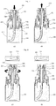
- FIG. 6 and 8 are views illustrating an operational state of a container for discharging powder according to an exemplary embodiment of the present invention.
- the guide protrusion 530 of the opening/closing member 500 ascends along the vertical guide groove 221 and the spiral guide groove 331 while the opening/closing member 500 is ascending. Due to this, the first sealing part 510 of the opening/closing member 500, closely contacted to an inner circumferential surface of the stem 300, gets separated from the inner circumferential surface of the stem 300, thus opening the movement hole 310.
- the guide protrusion 530 of the opening/closing member 500 descends along the vertical guide groove 221 and the spiral guide groove 331, thereby leading the opening/closing member 500 to descend. Due to this, the first sealing part 510 of the opening/closing member 500 gets closely contacted to an inner circumferential surface of the stem 300, thereby closing the movement hole 310.
- the powder moving through the content movement part 400 is not possible to move to an upper portion; therefore, powder can be prevented from being leaked through the discharging hole 210 no matter whether the container is dropped or shaken.
- the connecting hole 320 and the discharging hole 210 are configured to be dislocated.
- the present invention has a configuration wherein the opening/closing member 500 is inserted to the stem 300 in an interior of the button part 200 and ascends/descends according to rotation of the button part 200, thereby opening/closing the movement hole 310. Therefore, there arises no risk of losing the opening/closing member 500, and the problem that a user has to attach or detach the opening/closing member 500 on every use will be solved as well, thereby providing user convenience.
Landscapes
- Engineering & Computer Science (AREA)
- Mechanical Engineering (AREA)
- Containers And Packaging Bodies Having A Special Means To Remove Contents (AREA)
- Closures For Containers (AREA)
- Nozzles (AREA)
Claims (11)
- Behälter zum Abgeben von Pulver, umfassend:einen Behälterkörper (100), in dem Pulver aufbewahrt wird;einen Druckknopfteil (200), der drehbar an einem oberen Abschnitt des Behälterkörpers (100) angeordnet ist und gemäß Vorhandensein einer Druckbeaufschlagung durch einen Benutzer absteigt und gemäß Nichtvorhandensein einer Druckbeaufschlagung durch einen Benutzer aufsteigt, ferner umfassend ein Abgabeloch (210), in das Pulver abgegeben wird, an einer Seite davon;einen Schaft (300), der an einer Innenseite des Druckknopfteils (200) angeordnet ist und sich zusammen mit der Bewegung des Druckknopfteils (200) bewegt, umfassend ein Bewegungsloch (310) an einem oberen Abschnitt davon, so dass sich Pulver gemäß der Manipulation des Druckknopfteils (200) bewegen kann, und ferner umfassend, an einer Seite davon, ein Verbindungsloch (320), das mit dem Abgabeloch (210) verbunden ist, so dass das Pulver, das sich durch das Bewegungsloch (310) bewegt, durch das Abgabeloch (210) abgegeben werden kann;einen Inhaltsbewegungsteil (400), der an einer Innenseite des Schafts (300) angeordnet ist und getrennt einen Pulverbewegungskanal (410) bildet, in dem sich Pulver bewegt, und einen Luftbewegungskanal (420), in dem sich Luft bewegt; undwobei sich in dem Behälter zum Abgeben von Pulver ein Innendruck des Behälterkörpers (100) gemäß der Druckbeaufschlagung des Druckknopfteils (200) ändert und sich Pulver und Luft jeweils durch den Pulverbewegungskanal (410) in den Schaft (300) und den Luftbewegungskanal (420) zum Inhaltsbewegungsteil (400) bewegen, wodurch Pulver durch Luftdruck durch das Abgabeloch (210) abgegeben und gesprüht wird;wobei der Behälter zum Abgeben von Pulver durch ein Öffnungs-/Schließglied (500) gekennzeichnet ist, welches in einem oberen Abschnitt des Schafts (300) eingesetzt ist, das Bewegungsloch (310) aufsteigen lässt und öffnet, wenn der Druckknopfteil (200) sich zu einer Seitenrichtung dreht, und das Bewegungsloch (310) schließt, wenn der Druckknopfteil (200) sich zu der anderen Seitenrichtung dreht.
- Behälter zum Abgeben von Pulver nach Anspruch 1,
wobei ein Stützkörper (600), der mit einem oberen Abschnitt des Behälterkörpers (100) gekoppelt ist, einen Verlängerungsteil (610) umfasst, der sich zu einem unteren Abschnitt erstreckt, um eine obere innere Umfangsfläche des Behälterkörpers (100) an einer inneren Oberseite davon zu umschließen. - Behälter zum Abgeben von Pulver nach Anspruch 2,
wobei ein Kolben (700), der eng mit einer inneren Umfangsfläche des Verlängerungsteils (610) in Kontakt steht, um sich mit dem Auf-/Abstieg des Schafts (300) mitzubewegen, und dadurch einen Innendruck des Behälterkörpers (100) ändert, mit einem unteren Teil des Schafts (300) gekoppelt ist. - Behälter zum Abgeben von Pulver nach Anspruch 1,
wobei ein Vorsprungsteil (330), der eine spiralförmige Führungsnut (331) an beiden Seiten einer äußeren Umfangsfläche davon bildet, um den Auf-/Abstieg des Öffnungs-/Schließglieds (500) zu führen, an einem oberen Ende des Druckknopfteils (200) vorgesehen ist. - Behälter zum Abgeben von Pulver nach Anspruch 4,
wobei ein Führungsrohr (220), das den Auf-/Abstieg des Öffnungs-/Schließglieds (500) führt, an einer inneren oberen Seite des Druckknopfteils (200) vorgesehen ist, wobei eine vertikale Führungsnut (221) die vertikale Bewegung des Öffnungs-/Schließglieds (500) an beiden Seiten des Führungsrohrs (220) vorgesehen ist. - Behälter zum Abgeben von Pulver nach Anspruch 5,
wobei das Öffnungs-/Schließglied (500) Folgendes umfasst:ein erstes Dichtungsteil (510), das das Bewegungsloch (310) schließt, indem es in einem Zustand, in dem das Öffnungs-/Schließglied (500) abgesenkt ist, eng mit einer inneren Umfangsfläche des Schafts (300) in Kontakt gebracht wird, und das Bewegungsloch (310) öffnet, indem es in einem Zustand, in dem das Öffnungs-/Schließglied (500) angehoben ist, von einer inneren Umfangsfläche des Schafts (300) getrennt wird;ein zweites Dichtungsteil (520), das eng mit einer oberen inneren Umfangsfläche des Schafts (300) in Kontakt steht, so dass sich Pulver, das sich durch das Bewegungsloch (310) bewegt, zu einem oberen Teil des Schafts (300) und nicht zum Verbindungsteil (320) bewegen kann, wodurch verhindert wird, dass es ausläuft; undeinen Führungsvorsprung (530), der in die vertikale Führungsnut (221) und die spiralförmige Führungsnut (331) eingeführt ist und den Auf-/Abstieg des Öffnungs-/Schließglieds (500) so führt, dass er sich entlang der vertikalen Führungsnut (221) und der spiralförmigen Führungsnut (331) durch Drehen des Druckknopfteils (200) bewegt. - Behälter zum Abgeben von Pulver nach Anspruch 2,
wobei ein Drehverhinderungsvorsprung (340) in Längsrichtung an einer äußeren Umfangsfläche des Schafts (300) vorgesehen ist, um zu verhindern, dass sich der Schaft (300) dreht, wenn sich der Druckknopfteil (200) dreht, und eine Drehverhinderungsnut (650) an einer inneren Umfangsfläche des Stützkörpers (600) vorgesehen ist. - Behälter zum Abgeben von Pulver nach Anspruch 7,
wobei eine Pumpführungsnut (620), die einen Raum bildet, in dem der Druckknopfteil (200) auf-/absteigen kann, und einen Pumpverhinderungsvorsprung (630), der verhindert, dass sich der Druckknopfteil (200) nach unten bewegt, auf beiden Seiten einer äußeren Umfangsfläche des Schafts (300) vorgesehen sind. - Behälter zum Abgeben von Pulver nach Anspruch 8,
wobei an einer inneren Umfangsfläche des Druckknopfteils (200) ein Pumpführungsvorsprung (230) vorgesehen ist, der direkt über der Pumpführungsnut (620) angeordnet ist und sich entlang der Pumpführungsnut (620) bewegt, wenn der Druckknopfteil (200) sich in eine Seitenrichtung dreht, und direkt über dem Pumpverhinderungsvorsprung (630) angeordnet ist und verhindert, dass der Druckknopfteil (200) abfällt, wenn sich der Druckknopfteil (200) in die andere Seitenrichtung dreht. - Behälter zum Abgeben von Pulver nach Anspruch 1,
wobei an einem Ende eines Luftbewegungskanals (420) ein Luftkompressionsloch (421) vorgesehen ist, dessen Durchmesser kleiner als der eines Luftbewegungskanals (420) ist, so dass es möglich ist, Luft zu komprimieren und zu sprühen. - Behälter zum Abgeben von Pulver nach Anspruch 1,
wobei ein Pulverabsorptionsrohr (411), das das im Behälterkörper (100) aufbewahrte Pulver zu dem Pulverbewegungskanal (410) bewegt, an einen unteren Abschnitt des Pulverbewegungskanals (410) gekoppelt ist, wobei das Pulverabsorptionsrohr (411) sich je nach Vorhandensein/Nichtvorhandensein von Druckbeaufschlagung des Druckknopfteils (200) nach oben/unten bewegt und das im Behälterkörper (100) aufbewahrte Pulver rührt.
Applications Claiming Priority (2)
| Application Number | Priority Date | Filing Date | Title |
|---|---|---|---|
| KR1020160050865A KR101717972B1 (ko) | 2016-04-26 | 2016-04-26 | 파우더 토출 용기 |
| PCT/KR2016/010576 WO2017188521A1 (ko) | 2016-04-26 | 2016-09-22 | 파우더 토출 용기 |
Publications (3)
| Publication Number | Publication Date |
|---|---|
| EP3449762A1 EP3449762A1 (de) | 2019-03-06 |
| EP3449762A4 EP3449762A4 (de) | 2019-11-27 |
| EP3449762B1 true EP3449762B1 (de) | 2020-10-21 |
Family
ID=58502640
Family Applications (1)
| Application Number | Title | Priority Date | Filing Date |
|---|---|---|---|
| EP16820146.5A Active EP3449762B1 (de) | 2016-04-26 | 2016-09-22 | Pulverausgabebehälter |
Country Status (7)
| Country | Link |
|---|---|
| US (1) | US10507482B2 (de) |
| EP (1) | EP3449762B1 (de) |
| JP (1) | JP6909723B2 (de) |
| KR (1) | KR101717972B1 (de) |
| CN (1) | CN109068827B (de) |
| ES (1) | ES2830224T3 (de) |
| WO (1) | WO2017188521A1 (de) |
Families Citing this family (16)
| Publication number | Priority date | Publication date | Assignee | Title |
|---|---|---|---|---|
| KR101867566B1 (ko) * | 2016-07-01 | 2018-06-14 | (주)연우 | 이중 배출수단을 갖는 화장품 용기 |
| USD840820S1 (en) * | 2016-08-10 | 2019-02-19 | F.S.Korea Industries Inc. | Insert for cosmetic container |
| KR101959906B1 (ko) * | 2017-03-30 | 2019-07-15 | 펌텍코리아(주) | 잔여 내용물의 토출을 방지하는 화장품 용기 |
| KR101869042B1 (ko) | 2017-11-28 | 2018-06-20 | (주)연우 | 파우더 토출 용기 |
| CN107892102A (zh) * | 2017-12-22 | 2018-04-10 | 余姚晟祺塑业有限公司 | 一种喷头结构 |
| CN107934182A (zh) * | 2017-12-22 | 2018-04-20 | 余姚晟祺塑业有限公司 | 一种新型喷头 |
| KR101983819B1 (ko) * | 2018-06-20 | 2019-05-29 | (주)연우 | 파우더 토출 용기 |
| KR102079821B1 (ko) * | 2018-07-18 | 2020-02-20 | 넥스트바이오(주) | 안전캡을 구비한 액상음료 분사장치 |
| KR101920846B1 (ko) | 2018-08-17 | 2018-11-21 | 서현영 | 에어 튜브를 이용한 에코식 화장품 용기의 펌핑 장치 |
| KR102085710B1 (ko) * | 2018-11-07 | 2020-03-06 | (주)연우 | 파우더 토출 용기 |
| CN109907468B (zh) * | 2019-04-09 | 2023-12-29 | 广州市懂颜化妆品包装有限公司 | 一种彩妆瓶子改进结构 |
| CN113023090B (zh) * | 2020-08-31 | 2024-08-30 | 浙江晟祺实业有限公司 | 一种喷头改进结构 |
| KR200496339Y1 (ko) * | 2021-01-27 | 2023-01-06 | 주식회사 엘지생활건강 | 펌프 용기 |
| JP1736069S (ja) | 2021-09-30 | 2023-02-03 | 包装用容器 | |
| CN114558152B (zh) * | 2022-02-21 | 2023-08-22 | 成都润美玉之光医疗美容门诊部有限公司 | 一种闭合式入路自体肋软骨颗粒移植装置 |
| KR102631669B1 (ko) * | 2023-11-16 | 2024-01-30 | 민병선 | 펌핑식 화장품용기 |
Family Cites Families (26)
| Publication number | Priority date | Publication date | Assignee | Title |
|---|---|---|---|---|
| CH304560A (de) * | 1952-08-07 | 1955-01-15 | Hussein Pascha S E Ilhamy | Taschenzerstäuber. |
| US4157789A (en) * | 1977-11-10 | 1979-06-12 | Laauwe Robert H | Right-angle spray nozzle |
| US5203841A (en) * | 1986-04-25 | 1993-04-20 | Seiichi Kitabayashi | Dispensing head having a cap guard |
| US5228598A (en) * | 1990-07-17 | 1993-07-20 | Alexander Bally | Dilution apparatus with full opened or fully closed valve |
| DE4027749A1 (de) * | 1990-09-01 | 1992-03-05 | Pfeiffer Erich Gmbh & Co Kg | Austragvorrichtung fuer medien |
| US5082148A (en) * | 1990-10-09 | 1992-01-21 | Dunning Walter B | Powder dispenser |
| US5388730A (en) * | 1993-11-10 | 1995-02-14 | Enviro Pac International L.L.C. | Lockable actuator for a dispensing canister |
| US7434707B2 (en) * | 2001-08-21 | 2008-10-14 | Dispensing Patents International, Llc | Childproof attachment for a dispenser |
| KR200310093Y1 (ko) * | 2002-10-08 | 2003-04-08 | 강성일 | 뚜껑이 불필요한 출몰식 배출장치를 갖는 화장품 케이스 |
| FR2857343B1 (fr) * | 2003-07-08 | 2005-10-07 | Airlessystems | Tete de distribution de produit fluide |
| US7178694B2 (en) * | 2004-02-19 | 2007-02-20 | Saint-Gobain Calmar Inc. | Anti-clog discharge spout |
| ITMI20061561A1 (it) * | 2006-08-03 | 2008-02-04 | Microspray Delta Spa | Pompa di mandata chiudibile per sostanze fluide prelevabili da un contenitore |
| KR200440940Y1 (ko) * | 2006-11-10 | 2008-07-09 | (주)민진 | 회전펌프식 화장품 용기 |
| US7841494B2 (en) * | 2007-03-16 | 2010-11-30 | Randall Batinkoff | Pump dispenser |
| US7775737B2 (en) * | 2007-08-07 | 2010-08-17 | Deans David M | Hand-held cosmetic powder applicator brush apparatus |
| KR20090011156U (ko) * | 2008-04-28 | 2009-11-02 | (주)연우 | 튜브형 화장품용기 |
| CN201362423Y (zh) * | 2009-02-13 | 2009-12-16 | 深圳市通产丽星股份有限公司 | 外升式旋转出液包装容器 |
| KR20120002205U (ko) * | 2010-09-16 | 2012-03-26 | 펌텍코리아 (주) | 스포이드형 화장품 용기 |
| KR101192211B1 (ko) * | 2010-09-17 | 2012-10-17 | (주)연우 | 회전개폐형 브러시 튜브형 화장품용기 |
| KR101171305B1 (ko) | 2011-03-03 | 2012-08-20 | 정만택 | 화장용 파우더 용기 |
| CN102161025B (zh) * | 2011-04-01 | 2013-04-03 | 余姚晟祺塑业有限公司 | 能倒置使用的揿压式喷雾器 |
| ES2703533T3 (es) * | 2012-08-30 | 2019-03-11 | Zhejiang Jm Ind Co Ltd | Dispensador de polvo |
| CN105307948B (zh) * | 2013-05-12 | 2017-10-20 | 佳尼雍株式会社 | 按压式分配器 |
| CN203388445U (zh) * | 2013-08-14 | 2014-01-15 | 东莞俪宝塑胶制品有限公司 | 一种眼彩笔盒结构 |
| KR101570132B1 (ko) * | 2013-12-27 | 2015-11-19 | (주)연우 | 화장퍼프를 구비한 튜브용기 |
| KR101378719B1 (ko) | 2014-01-24 | 2014-03-27 | (주)연우 | 파우더 토출 용기 |
-
2016
- 2016-04-26 KR KR1020160050865A patent/KR101717972B1/ko active Active
- 2016-09-22 ES ES16820146T patent/ES2830224T3/es active Active
- 2016-09-22 CN CN201680002481.7A patent/CN109068827B/zh active Active
- 2016-09-22 JP JP2017500847A patent/JP6909723B2/ja active Active
- 2016-09-22 EP EP16820146.5A patent/EP3449762B1/de active Active
- 2016-09-22 US US15/324,163 patent/US10507482B2/en active Active
- 2016-09-22 WO PCT/KR2016/010576 patent/WO2017188521A1/ko not_active Ceased
Non-Patent Citations (1)
| Title |
|---|
| None * |
Also Published As
| Publication number | Publication date |
|---|---|
| JP6909723B2 (ja) | 2021-07-28 |
| US10507482B2 (en) | 2019-12-17 |
| US20180178232A1 (en) | 2018-06-28 |
| WO2017188521A1 (ko) | 2017-11-02 |
| EP3449762A4 (de) | 2019-11-27 |
| CN109068827B (zh) | 2021-06-29 |
| KR101717972B1 (ko) | 2017-03-20 |
| CN109068827A (zh) | 2018-12-21 |
| JP2019519253A (ja) | 2019-07-11 |
| EP3449762A1 (de) | 2019-03-06 |
| ES2830224T3 (es) | 2021-06-03 |
Similar Documents
| Publication | Publication Date | Title |
|---|---|---|
| EP3449762A1 (de) | Pulverausgabebehälter | |
| US9924775B2 (en) | Powder discharging container | |
| EP2995571A1 (de) | Pumpenartiger kosmetikbehälter mit seitlichem knopf | |
| KR101631827B1 (ko) | 펌프 타입 컴팩트 용기 | |
| EP3420843A1 (de) | Pumpenartiger kosmetikbehälter mit seitlichem knopf | |
| KR101487191B1 (ko) | 크림타입 화장품 용기 | |
| KR20210102166A (ko) | 탄성 부재 및 이를 포함하는 펌프 조립체 | |
| EP3187432A1 (de) | Spenderbehälter | |
| EP1880631A2 (de) | Kosmetikbehälter | |
| EP3123897A2 (de) | Behälter für cremeartiges kosmetikum | |
| KR100462967B1 (ko) | 액체또는호상물배출용기및그조립방법 | |
| EP3238564A1 (de) | Pumpenartiger, mit seitlichem knopf ausgestatteter kosmetikbehälter | |
| CN104717901A (zh) | 膏型化妆品容器 | |
| CN113827023A (zh) | 容器 | |
| US10934077B2 (en) | Powder dispensing container | |
| EP3228212A1 (de) | Dichtungsstruktur für einen behälter von kosmetik in cremeform | |
| EP3750440A1 (de) | Fluidbehälter | |
| KR100566823B1 (ko) | 화장액 도포용구 | |
| KR20160109277A (ko) | 크림타입 화장품용기 | |
| KR102781234B1 (ko) | 화장품 용기 | |
| EP3811814A1 (de) | Pulverausgabebehälter | |
| KR102730461B1 (ko) | 내용물 용기 |
Legal Events
| Date | Code | Title | Description |
|---|---|---|---|
| STAA | Information on the status of an ep patent application or granted ep patent |
Free format text: STATUS: UNKNOWN |
|
| STAA | Information on the status of an ep patent application or granted ep patent |
Free format text: STATUS: THE INTERNATIONAL PUBLICATION HAS BEEN MADE |
|
| PUAI | Public reference made under article 153(3) epc to a published international application that has entered the european phase |
Free format text: ORIGINAL CODE: 0009012 |
|
| STAA | Information on the status of an ep patent application or granted ep patent |
Free format text: STATUS: REQUEST FOR EXAMINATION WAS MADE |
|
| 17P | Request for examination filed |
Effective date: 20170216 |
|
| AK | Designated contracting states |
Kind code of ref document: A1 Designated state(s): AL AT BE BG CH CY CZ DE DK EE ES FI FR GB GR HR HU IE IS IT LI LT LU LV MC MK MT NL NO PL PT RO RS SE SI SK SM TR |
|
| AX | Request for extension of the european patent |
Extension state: BA ME |
|
| DAV | Request for validation of the european patent (deleted) | ||
| DAX | Request for extension of the european patent (deleted) | ||
| A4 | Supplementary search report drawn up and despatched |
Effective date: 20191030 |
|
| RIC1 | Information provided on ipc code assigned before grant |
Ipc: B05B 11/00 20060101ALI20191024BHEP Ipc: A45D 33/02 20060101AFI20191024BHEP Ipc: B05B 11/06 20060101ALI20191024BHEP Ipc: A45D 33/08 20060101ALI20191024BHEP Ipc: B65D 83/00 20060101ALI20191024BHEP Ipc: A45D 33/00 20060101ALI20191024BHEP Ipc: B65D 47/00 20060101ALI20191024BHEP |
|
| GRAP | Despatch of communication of intention to grant a patent |
Free format text: ORIGINAL CODE: EPIDOSNIGR1 |
|
| STAA | Information on the status of an ep patent application or granted ep patent |
Free format text: STATUS: GRANT OF PATENT IS INTENDED |
|
| INTG | Intention to grant announced |
Effective date: 20200806 |
|
| GRAS | Grant fee paid |
Free format text: ORIGINAL CODE: EPIDOSNIGR3 |
|
| GRAA | (expected) grant |
Free format text: ORIGINAL CODE: 0009210 |
|
| STAA | Information on the status of an ep patent application or granted ep patent |
Free format text: STATUS: THE PATENT HAS BEEN GRANTED |
|
| AK | Designated contracting states |
Kind code of ref document: B1 Designated state(s): AL AT BE BG CH CY CZ DE DK EE ES FI FR GB GR HR HU IE IS IT LI LT LU LV MC MK MT NL NO PL PT RO RS SE SI SK SM TR |
|
| REG | Reference to a national code |
Ref country code: GB Ref legal event code: FG4D |
|
| REG | Reference to a national code |
Ref country code: CH Ref legal event code: EP |
|
| REG | Reference to a national code |
Ref country code: IE Ref legal event code: FG4D |
|
| REG | Reference to a national code |
Ref country code: DE Ref legal event code: R096 Ref document number: 602016046379 Country of ref document: DE |
|
| REG | Reference to a national code |
Ref country code: AT Ref legal event code: REF Ref document number: 1324935 Country of ref document: AT Kind code of ref document: T Effective date: 20201115 |
|
| REG | Reference to a national code |
Ref country code: AT Ref legal event code: MK05 Ref document number: 1324935 Country of ref document: AT Kind code of ref document: T Effective date: 20201021 |
|
| REG | Reference to a national code |
Ref country code: NL Ref legal event code: MP Effective date: 20201021 |
|
| PG25 | Lapsed in a contracting state [announced via postgrant information from national office to epo] |
Ref country code: GR Free format text: LAPSE BECAUSE OF FAILURE TO SUBMIT A TRANSLATION OF THE DESCRIPTION OR TO PAY THE FEE WITHIN THE PRESCRIBED TIME-LIMIT Effective date: 20210122 Ref country code: FI Free format text: LAPSE BECAUSE OF FAILURE TO SUBMIT A TRANSLATION OF THE DESCRIPTION OR TO PAY THE FEE WITHIN THE PRESCRIBED TIME-LIMIT Effective date: 20201021 Ref country code: PT Free format text: LAPSE BECAUSE OF FAILURE TO SUBMIT A TRANSLATION OF THE DESCRIPTION OR TO PAY THE FEE WITHIN THE PRESCRIBED TIME-LIMIT Effective date: 20210222 Ref country code: RS Free format text: LAPSE BECAUSE OF FAILURE TO SUBMIT A TRANSLATION OF THE DESCRIPTION OR TO PAY THE FEE WITHIN THE PRESCRIBED TIME-LIMIT Effective date: 20201021 Ref country code: NO Free format text: LAPSE BECAUSE OF FAILURE TO SUBMIT A TRANSLATION OF THE DESCRIPTION OR TO PAY THE FEE WITHIN THE PRESCRIBED TIME-LIMIT Effective date: 20210121 |
|
| REG | Reference to a national code |
Ref country code: LT Ref legal event code: MG4D |
|
| PG25 | Lapsed in a contracting state [announced via postgrant information from national office to epo] |
Ref country code: AT Free format text: LAPSE BECAUSE OF FAILURE TO SUBMIT A TRANSLATION OF THE DESCRIPTION OR TO PAY THE FEE WITHIN THE PRESCRIBED TIME-LIMIT Effective date: 20201021 Ref country code: LV Free format text: LAPSE BECAUSE OF FAILURE TO SUBMIT A TRANSLATION OF THE DESCRIPTION OR TO PAY THE FEE WITHIN THE PRESCRIBED TIME-LIMIT Effective date: 20201021 Ref country code: PL Free format text: LAPSE BECAUSE OF FAILURE TO SUBMIT A TRANSLATION OF THE DESCRIPTION OR TO PAY THE FEE WITHIN THE PRESCRIBED TIME-LIMIT Effective date: 20201021 Ref country code: IS Free format text: LAPSE BECAUSE OF FAILURE TO SUBMIT A TRANSLATION OF THE DESCRIPTION OR TO PAY THE FEE WITHIN THE PRESCRIBED TIME-LIMIT Effective date: 20210221 Ref country code: BG Free format text: LAPSE BECAUSE OF FAILURE TO SUBMIT A TRANSLATION OF THE DESCRIPTION OR TO PAY THE FEE WITHIN THE PRESCRIBED TIME-LIMIT Effective date: 20210121 Ref country code: SE Free format text: LAPSE BECAUSE OF FAILURE TO SUBMIT A TRANSLATION OF THE DESCRIPTION OR TO PAY THE FEE WITHIN THE PRESCRIBED TIME-LIMIT Effective date: 20201021 |
|
| REG | Reference to a national code |
Ref country code: ES Ref legal event code: FG2A Ref document number: 2830224 Country of ref document: ES Kind code of ref document: T3 Effective date: 20210603 |
|
| PG25 | Lapsed in a contracting state [announced via postgrant information from national office to epo] |
Ref country code: HR Free format text: LAPSE BECAUSE OF FAILURE TO SUBMIT A TRANSLATION OF THE DESCRIPTION OR TO PAY THE FEE WITHIN THE PRESCRIBED TIME-LIMIT Effective date: 20201021 Ref country code: NL Free format text: LAPSE BECAUSE OF FAILURE TO SUBMIT A TRANSLATION OF THE DESCRIPTION OR TO PAY THE FEE WITHIN THE PRESCRIBED TIME-LIMIT Effective date: 20201021 |
|
| REG | Reference to a national code |
Ref country code: DE Ref legal event code: R097 Ref document number: 602016046379 Country of ref document: DE |
|
| PG25 | Lapsed in a contracting state [announced via postgrant information from national office to epo] |
Ref country code: SK Free format text: LAPSE BECAUSE OF FAILURE TO SUBMIT A TRANSLATION OF THE DESCRIPTION OR TO PAY THE FEE WITHIN THE PRESCRIBED TIME-LIMIT Effective date: 20201021 Ref country code: RO Free format text: LAPSE BECAUSE OF FAILURE TO SUBMIT A TRANSLATION OF THE DESCRIPTION OR TO PAY THE FEE WITHIN THE PRESCRIBED TIME-LIMIT Effective date: 20201021 Ref country code: LT Free format text: LAPSE BECAUSE OF FAILURE TO SUBMIT A TRANSLATION OF THE DESCRIPTION OR TO PAY THE FEE WITHIN THE PRESCRIBED TIME-LIMIT Effective date: 20201021 Ref country code: SM Free format text: LAPSE BECAUSE OF FAILURE TO SUBMIT A TRANSLATION OF THE DESCRIPTION OR TO PAY THE FEE WITHIN THE PRESCRIBED TIME-LIMIT Effective date: 20201021 Ref country code: CZ Free format text: LAPSE BECAUSE OF FAILURE TO SUBMIT A TRANSLATION OF THE DESCRIPTION OR TO PAY THE FEE WITHIN THE PRESCRIBED TIME-LIMIT Effective date: 20201021 Ref country code: EE Free format text: LAPSE BECAUSE OF FAILURE TO SUBMIT A TRANSLATION OF THE DESCRIPTION OR TO PAY THE FEE WITHIN THE PRESCRIBED TIME-LIMIT Effective date: 20201021 |
|
| PLBE | No opposition filed within time limit |
Free format text: ORIGINAL CODE: 0009261 |
|
| STAA | Information on the status of an ep patent application or granted ep patent |
Free format text: STATUS: NO OPPOSITION FILED WITHIN TIME LIMIT |
|
| PG25 | Lapsed in a contracting state [announced via postgrant information from national office to epo] |
Ref country code: DK Free format text: LAPSE BECAUSE OF FAILURE TO SUBMIT A TRANSLATION OF THE DESCRIPTION OR TO PAY THE FEE WITHIN THE PRESCRIBED TIME-LIMIT Effective date: 20201021 |
|
| 26N | No opposition filed |
Effective date: 20210722 |
|
| PG25 | Lapsed in a contracting state [announced via postgrant information from national office to epo] |
Ref country code: AL Free format text: LAPSE BECAUSE OF FAILURE TO SUBMIT A TRANSLATION OF THE DESCRIPTION OR TO PAY THE FEE WITHIN THE PRESCRIBED TIME-LIMIT Effective date: 20201021 Ref country code: IT Free format text: LAPSE BECAUSE OF FAILURE TO SUBMIT A TRANSLATION OF THE DESCRIPTION OR TO PAY THE FEE WITHIN THE PRESCRIBED TIME-LIMIT Effective date: 20201021 |
|
| PG25 | Lapsed in a contracting state [announced via postgrant information from national office to epo] |
Ref country code: SI Free format text: LAPSE BECAUSE OF FAILURE TO SUBMIT A TRANSLATION OF THE DESCRIPTION OR TO PAY THE FEE WITHIN THE PRESCRIBED TIME-LIMIT Effective date: 20201021 |
|
| REG | Reference to a national code |
Ref country code: CH Ref legal event code: PL |
|
| REG | Reference to a national code |
Ref country code: BE Ref legal event code: MM Effective date: 20210930 |
|
| PG25 | Lapsed in a contracting state [announced via postgrant information from national office to epo] |
Ref country code: IS Free format text: LAPSE BECAUSE OF FAILURE TO SUBMIT A TRANSLATION OF THE DESCRIPTION OR TO PAY THE FEE WITHIN THE PRESCRIBED TIME-LIMIT Effective date: 20210221 Ref country code: MC Free format text: LAPSE BECAUSE OF FAILURE TO SUBMIT A TRANSLATION OF THE DESCRIPTION OR TO PAY THE FEE WITHIN THE PRESCRIBED TIME-LIMIT Effective date: 20201021 |
|
| PG25 | Lapsed in a contracting state [announced via postgrant information from national office to epo] |
Ref country code: LU Free format text: LAPSE BECAUSE OF NON-PAYMENT OF DUE FEES Effective date: 20210922 Ref country code: IE Free format text: LAPSE BECAUSE OF NON-PAYMENT OF DUE FEES Effective date: 20210922 Ref country code: BE Free format text: LAPSE BECAUSE OF NON-PAYMENT OF DUE FEES Effective date: 20210930 |
|
| PG25 | Lapsed in a contracting state [announced via postgrant information from national office to epo] |
Ref country code: LI Free format text: LAPSE BECAUSE OF NON-PAYMENT OF DUE FEES Effective date: 20210930 Ref country code: CH Free format text: LAPSE BECAUSE OF NON-PAYMENT OF DUE FEES Effective date: 20210930 |
|
| PG25 | Lapsed in a contracting state [announced via postgrant information from national office to epo] |
Ref country code: CY Free format text: LAPSE BECAUSE OF FAILURE TO SUBMIT A TRANSLATION OF THE DESCRIPTION OR TO PAY THE FEE WITHIN THE PRESCRIBED TIME-LIMIT Effective date: 20201021 |
|
| PG25 | Lapsed in a contracting state [announced via postgrant information from national office to epo] |
Ref country code: HU Free format text: LAPSE BECAUSE OF FAILURE TO SUBMIT A TRANSLATION OF THE DESCRIPTION OR TO PAY THE FEE WITHIN THE PRESCRIBED TIME-LIMIT; INVALID AB INITIO Effective date: 20160922 |
|
| PG25 | Lapsed in a contracting state [announced via postgrant information from national office to epo] |
Ref country code: MK Free format text: LAPSE BECAUSE OF FAILURE TO SUBMIT A TRANSLATION OF THE DESCRIPTION OR TO PAY THE FEE WITHIN THE PRESCRIBED TIME-LIMIT Effective date: 20201021 |
|
| PG25 | Lapsed in a contracting state [announced via postgrant information from national office to epo] |
Ref country code: TR Free format text: LAPSE BECAUSE OF FAILURE TO SUBMIT A TRANSLATION OF THE DESCRIPTION OR TO PAY THE FEE WITHIN THE PRESCRIBED TIME-LIMIT Effective date: 20201021 |
|
| PG25 | Lapsed in a contracting state [announced via postgrant information from national office to epo] |
Ref country code: MT Free format text: LAPSE BECAUSE OF FAILURE TO SUBMIT A TRANSLATION OF THE DESCRIPTION OR TO PAY THE FEE WITHIN THE PRESCRIBED TIME-LIMIT Effective date: 20201021 |
|
| PGFP | Annual fee paid to national office [announced via postgrant information from national office to epo] |
Ref country code: DE Payment date: 20250702 Year of fee payment: 10 |
|
| PGFP | Annual fee paid to national office [announced via postgrant information from national office to epo] |
Ref country code: GB Payment date: 20250703 Year of fee payment: 10 |
|
| PGFP | Annual fee paid to national office [announced via postgrant information from national office to epo] |
Ref country code: FR Payment date: 20250808 Year of fee payment: 10 |
|
| PGFP | Annual fee paid to national office [announced via postgrant information from national office to epo] |
Ref country code: ES Payment date: 20251016 Year of fee payment: 10 |