EP3449772B1 - Bestuhlungssystem - Google Patents
Bestuhlungssystem Download PDFInfo
- Publication number
- EP3449772B1 EP3449772B1 EP18192774.0A EP18192774A EP3449772B1 EP 3449772 B1 EP3449772 B1 EP 3449772B1 EP 18192774 A EP18192774 A EP 18192774A EP 3449772 B1 EP3449772 B1 EP 3449772B1
- Authority
- EP
- European Patent Office
- Prior art keywords
- seat shell
- seating system
- arm
- seat
- swivel
- Prior art date
- Legal status (The legal status is an assumption and is not a legal conclusion. Google has not performed a legal analysis and makes no representation as to the accuracy of the status listed.)
- Active
Links
Images



Classifications
-
- A—HUMAN NECESSITIES
- A47—FURNITURE; DOMESTIC ARTICLES OR APPLIANCES; COFFEE MILLS; SPICE MILLS; SUCTION CLEANERS IN GENERAL
- A47C—CHAIRS; SOFAS; BEDS
- A47C9/00—Stools for specified purposes
- A47C9/02—Office stools; Workshop stools
- A47C9/022—Office stools; Workshop stools movably mounted on a working-table or the like
-
- A—HUMAN NECESSITIES
- A47—FURNITURE; DOMESTIC ARTICLES OR APPLIANCES; COFFEE MILLS; SPICE MILLS; SUCTION CLEANERS IN GENERAL
- A47C—CHAIRS; SOFAS; BEDS
- A47C9/00—Stools for specified purposes
- A47C9/02—Office stools; Workshop stools
-
- A—HUMAN NECESSITIES
- A47—FURNITURE; DOMESTIC ARTICLES OR APPLIANCES; COFFEE MILLS; SPICE MILLS; SUCTION CLEANERS IN GENERAL
- A47B—TABLES; DESKS; OFFICE FURNITURE; CABINETS; DRAWERS; GENERAL DETAILS OF FURNITURE
- A47B83/00—Combinations comprising two or more pieces of furniture of different kinds
- A47B83/02—Tables combined with seats
-
- A—HUMAN NECESSITIES
- A47—FURNITURE; DOMESTIC ARTICLES OR APPLIANCES; COFFEE MILLS; SPICE MILLS; SUCTION CLEANERS IN GENERAL
- A47C—CHAIRS; SOFAS; BEDS
- A47C1/00—Chairs adapted for special purposes
- A47C1/12—Theatre, auditorium or similar chairs
Definitions
- the invention relates to a seating system according to the preamble of claim 1.
- Seating systems of this type are used in particular in auditoriums, auditoriums, meeting rooms, counters, etc. and are usually designed as stationary row seating.
- Such a seating system is for example in the Swiss patent CH651738A5 shown and has a stand with a table top and with a support arm connected to the stand, which carries a seat at its free end, the support arm and seat being pivotable from an end position into a use position in the horizontal plane.
- the US6899385B2 discloses a comparable seating system for lecture halls and classrooms and the like, which additionally shows a mechanism for the resilient mounting and adjustment of the seat.
- the US2024045A shows another seating system which can be considered useful for understanding the invention.
- the seating system according to the preamble of claim 1 therefore has a lifting element which moves the seat shell between a locked position and a seated position, the seat shell being locked in a locked position in the unloaded state to prevent the seat pan from pivoting relative to the support arm.
- the seat shell can be unlocked in the loaded state in order to allow the seat shell to pivot.
- load is understood to mean, in particular, the sitting down of a person on the seat shell, with the result that the person loads the seat shell and thus the lifting element with its weight.
- the lifting element is designed as a gas pressure spring.
- gas pressure springs are that, in addition to their spring force, they are equipped with an integrated damping mechanism, which, together with the constant release of force, leads to smooth, jerk-free swiveling movements without abrupt movement stops.
- the seat shell can be provided with a reset device which automatically swivels the seat shell back from a sitting position into the blocking position.
- the reset device can be formed by the lifting element, which is designed in particular as a gas pressure spring, and by a first guide element, a control surface being arranged on the first guide element, which converts the lifting movement of the lifting element into a rotary movement in conjunction with a second guide element.
- the lifting element designed as a gas pressure spring is arranged at the free end of the support arm in a receiving pot, the cylinder housing of the gas pressure spring being firmly connected to the receiving pot and the seat shell being connected to the piston rod of the gas pressure spring.
- the piston rod is mounted in the cylinder housing in such a way that it can be rotated about its own longitudinal axis.
- gas pressure springs is preferred because it increases the convenience of use compared to conventional springs and avoids noise.
- the first guide element can have stop lugs. If the first guide element is arranged at the upper end of the receptacle, this can preferably be designed as a stop ring on which the stop lugs are molded.
- This counter element can be designed as a profile rod, which is attached eccentrically to the axis of rotation on the seat shell.
- the control surface of the first guide element can be formed on the underside of a spring tongue projecting outwards on the outer circumference of the stop ring, as seen in the radial direction, the spring tongue or at least the control surface being inclined with respect to the plane of the stop ring.
- the control surface cooperates with a second guide element, which can be attached to the free end of the profile bar.
- the second guide element can preferably be designed as a ball bearing.
- the ball bearing is arranged so that the axis of rotation of the ball bearing is aligned radially to the axis of rotation of the seat shell. This enables the ball bearing to roll on the control surface when the seat shell is rotated.
- the stop ring can have, for example, a section which is delimited by two stop lugs and cooperates with the second guide element, the second guide element and the stops only being operatively engaged when the gas pressure spring is in the unloaded state and the piston is at its maximum out of the cylinder housing is extended.
- the free end of the spring tongue projecting outwards can advantageously be shaped like a hook, in order to form one of the stop lugs.
- the support arm is formed in two parts and consists of one connected to the upright Holding arm and a swivel arm connected to the seat shell, the holding arm and swivel arm being connected to one another via a swivel joint.
- This swivel joint can be formed from a cylinder liner attached to the front of the swivel arm and a receiving jaw attached to the free end of the holding arm, which are connected to one another by a bearing pin.
- Another gas pressure spring is advantageously installed in or on the holding arm, the piston rod of which is connected to the receiving cylinder of the swivel arm. As a result, the further gas pressure spring can push the swivel arm and thus the seat shell into the end position.
- the previously described mode of operation of a gas pressure spring increases comfort in that the pivoting movements are carried out evenly and without abrupt stops.
- an upright carries two seat units, which are preferably each formed from a holding arm, a swivel arm and a seat shell.
- an upright of the seating system according to the invention can be designed as a hollow profile and in the interior of the hollow profile electrical supply lines can be led to the underside of the table top.
- the backrest of the rotatable seat shell preferably does not strike the table top or an adjacent seat unit when the support arm is pivoted from the locked position into the sitting position and vice versa.
- the resetting of the seat shell into the locking position when the user stands up is quicker than the resetting of the support arm into the locking position. This prevents damage to the backrest and the edge of the table.
- FIGS. 1 and 2 show a perspective view of a swivel arm 14 used in a seating system according to the invention with a lifting element 21 and a seat support 12 with a different stroke.
- the lifting element 21 is installed in a receiving pot 22 and according to the embodiment Figure 1 designed as a gas pressure spring.
- the cylinder housing of the gas pressure spring is not visible.
- a stop ring 24 surrounding it is mounted on the upper side of the receptacle 22 .
- This has two stop lugs 27, 27 ', a cap-like plastic stop 28 being attached to the stop lug 27.
- the stop ring 24 has a spring tongue 26 which is integrally formed on the outer circumference of the stop ring 24 and the free end of which is slightly spaced from the outer circumference.
- the base of the spring tongue 26 connects directly to the stop lug 27 '.
- the spring tongue 26 is also opposite the Plane of the stop ring 24 inclined, in other words the spring tongue 26 is bent downward to a small extent.
- the underside of the spring tongue 26 forms a control surface 35, which cooperates with a counter-element 23 explained below.
- This counter element 23 is designed as a channel-like profile part 36, which is mounted eccentrically on the seat support 12. Here, the channel is oriented inwards to the axis of rotation A of the seat support 12 and parallel to this.
- a profile rod 37 is formed with a bore 38 through which a flat-head screw 33 is inserted, which serves as an axis for a ball bearing 31.
- the ball bearing 31 and the flat head screw 33 and a washer 34 are secured against falling out by means of a head nut 32.
- the ball bearing 31 is installed on the side of the stop ring 24 facing the side of the stop ring 24 together with a washer 34, and the flat-head screw 33 extends in the radial direction with respect to the axis of rotation A. Details of the essentially from the ball bearing 31 and the profile rod 37 formed second guide element 55 are the Figure 8 refer to.
- the seat support 12 is mounted on the end of a piston rod 29 of the lifting element 21 designed as a gas pressure spring.
- the longitudinal axis of the gas pressure spring simultaneously forms the axis of rotation A about which the seat support 12 can be rotated.
- the seat support is in the unloaded state, which means that the compression spring is loaded with no or only a very small weight.
- the piston rod 29 is thus extended to the maximum.
- This position of the piston rod 29 has the result that the ball bearing 31 is located between the stop lugs 27 and 27 '.
- these stop lugs block any rotational movement of the seat carrier and thus the in Figure 1 Seat shell 11, not shown.
- the seat support 12 is thus in a locked position.
- the seat shell 11 remains in the locked position.
- the counter element 23 installed on the seat support 12 is also moved downward, with the result that the ball bearing 31 is no longer located between the two stop lugs 27 and 27 '(see here Fig. 2 ).
- the seat shell 11 is now rotatable.
- the stop lug 27 forms a further limitation of the play in the rotational movement.
- the seat pan 11 can only be moved in the direction of arrow B from this released blocking position.
- the lifting element 31 lifts the seat shell and thus the counter element 23 again.
- This lifting movement is carried out until the running surface of the ball bearing 31 meets the control surface 35. Because this control surface 35 is inclined with respect to the plane of the stop ring 24 and because the lifting element continues to push the entire arrangement of seat surface and counter element 23 upwards, the ball bearing rolls along the control surface and the lifting movement is converted into a rotary movement. This process lasts until the profile rod 37 in turn strikes the stop nose 27 '. Finally, a vertical lifting movement is then carried out again, which brings the ball bearing 31 into the locked position between the stop lugs 27 and 27 '.
- the stop lug 27 is covered with a cap-like plastic stop 28, which reduces the noise when the profile rod 37 strikes the stop 27 and has a damping effect.
- FIG 4 shows a perspective view of a seating system according to the invention in a two-seat embodiment with swivel arms 14, 14 'in the end position and with seat elements in their respective locking positions.
- a seat element in the form of a seat shell 11 is shown, the seat support not being shown in the figure and a seat support 12.
- the seat support and seat element can be connected to one another in a known manner.
- the seat support and seat element are screwed.
- the swivel arms 14, 14 ' are articulated on holding arms 15, 15'.
- a support profile is attached, which carries a table top, not shown.
- the upright 16 is designed as a hollow profile and has semicircular recesses. In the interior of the hollow profile, electrical lines for power supply or for information transmission can be routed, which can be led through the recesses 49, 49 'to the underside of the table top or to sockets built into or attached to the table top.
- FIG 5 is a perspective view of a seating system according to the invention Figure 4 shown with seat elements according to Figure 4 in a sitting position and with swivel arms 14, 14 'in free positions. It is easy to imagine how the seat shell 11 is aligned with the table edge, not shown. The holding arms 14, 14 'are in relation to their position in Figure 4 pivoted to the rear, the seat elements are shown in the loaded position in the sitting position.
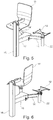
- FIG 6 is a perspective view of a seating system according to the invention Figure 4 shown with seat elements according to Figure 4 in the locked position and with swivel arms 14, 14 'in free positions. It can be seen here how the seat shell 11 is pivoted by approximately 90 ° relative to the table top 54 indicated by dashed lines. It is conceivable that a seat shell 11 made accessible in this way can be comfortably reached and a person can sit down without any effort.
- FIG 7 a lifting element 21 designed as a gas pressure spring is shown in perspective. Note that this is an exploded view. Basically, the stop ring 24 with the plastic stop 28 and the stop lugs 27 and 27 'is placed centrally on the cylinder housing of the gas pressure spring.
- the ring When installed, the ring lies - as in, for example Figure 1 recognizable - slightly below the upper edge of the receptacle 22.
- the receptacle 22 has an L-shaped guide slots 58 and 59, into which pins 56 and 57 which are directed radially inwards and are formed on the stop ring 24 can be inserted.
- the stop ring 24 can thus be rotated to a limited extent.
- the stop ring is firmly fixed with screws.
- the rotatable arrangement of the stop ring 24 makes it possible to determine the extent to which the seat shell 11 can be rotated, because the positions of the stops 26, 27 and 27 'are of course also determined by the positioning and fixing of the stop ring 24.
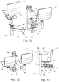
- FIG 11 shows a perspective view of a seating system according to the invention Figures 4 to 6 with elements partially shown in exploded view.
- the support arms are each realized from the holding arms 14 and 14 'or 15 and 15'.
- a joint which consists of a bearing pin 53, a holding cylinder 51 and holding jaws 52.
- Brass sleeves are inserted on the top and bottom of the receiving cylinder to enable maintenance-free plain bearings.
- cover 17 To cover the mechanics installed in the holding arms 15 and 15 ', these are covered with a cover 17.
- Figure 12 shows a perspective view of a seating system according to the invention Figure 11 with seat shells 11, 11 ', swivel arms 14, 14', holding arms 15, 15 ', it should be noted that the holding arm 15' is covered by the cover 17.
- the seat shells 11, 11 ' are in their locked position and the swivel arms 14, 14' are in the end position.
- FIG 13 is a section through a seating system according to the invention Figure 12 shown.
- the holding arm 15 is a hollow profile, in the interior of which a mechanism is installed.
- the mechanism has the task of pivoting the swivel arm 14 by means of the further gas pressure spring 41 installed in the receptacle 22.
- the gas pressure spring 41 ensures that the seat shell 11 ′ mounted on the swivel arm 14 is moved into the end position in the unused state.
- the backrest of the seat pan 11 is arranged in the end position with a minimal distance from the table top 54. Lying on the edge of the table top 54 should be avoided in order to avoid impact noises when pivoting back.
- the gas pressure spring 41 like the gas pressure spring used in the lifting element 21, is constructed in a known manner and has a cylinder housing 43 from which a displaceably mounted piston rod 44 emerges. At the end of the piston rod 44, a fork head 45 is attached, which is articulated on a receiving tab 46 of the swivel arm 14. In the unloaded state, the piston rod 44 is extended to the maximum and thus presses the swivel arm 14 into the end position.
- the gas pressure spring 41 is fixed in the hollow profile by means of a flange 42 which is connected to the cylinder housing 43. In order to apply the forces required for pivoting, the exemplary embodiment according to Figure 13 two identical gas pressure springs installed.
Landscapes
- Chairs Characterized By Structure (AREA)
Description
- Die Erfindung betrifft ein Bestuhlungssystem gemäss Oberbegriff des Anspruchs 1. Derartige Bestuhlungssysteme werden insbesondere in Hörsälen, Auditorien, Besprechungsräumen, Theken usw. eingesetzt und sind meist als stationäre Reihenbestuhlung ausgeführt.
- Ein derartiges Bestuhlungssystem ist beispielsweise in der Schweizer Patentschrift
CH651738A5 - Die
US6899385B2 offenbart ein vergleichbares ein Bestuhlungssystem für Hörsäle und Klassenräume und dergleichen, welches zusätzlich eine Mechanik zur federnden Lagerung und Verstellung des Sitzes zeigt. - Die
US2024045A zeigt ein weiteres Bestuhlungssystem, welches für das Verständnis der Erfindung als nützlich angesehen werden kann. - Es ist eine Aufgabe der vorliegenden Erfindung, eine alternatives Bestuhlungssystem bereitzustellen und dieses hierbei hinsichtlich der Schwenkfunktion und des Nutzungskomforts zu verbessern. Unter anderem soll der Zugang zur Sitzfläche erleichtert werden. Ein weiteres Ziel ist, dass das Bestuhlungssystem eine möglichst lange Lebensdauer hat und dabei wenig anfällig für Beschädigungen ist.
- Gelöst wird diese Aufgabe durch ein Bestuhlungssystem mit den Merkmalen des Anspruchs 1. Erfindungsgemäss weist daher das Bestuhlungssystem gemäss Oberbegriff des Anspruchs 1 ein Hubelement auf, welches die Sitzschale zwischen einer Sperrposition und einer Sitzposition bewegt, wobei die Sitzschale im unbelasteten Zustand in einer Sperrposition verriegelt ist, um ein Verschwenken der Sitzschale gegenüber dem Trägerarm zu verhindern.
- Die im Folgenden angeführten vorteilhaften Ausführungsvarianten führen allein oder in Kombination miteinander zu weiteren Verbesserungen des erfindungsgemässen Bestuhlungssystems.
- So kann gemäss einer ersten Ausführungsform der Erfindung die Sitzschale im belasteten Zustand entriegelt werden, um ein Verschwenken der Sitzschale zu ermöglichen. Unter Belastung ist hierbei insbesondere das Hinsetzen einer Person auf die Sitzschale zu verstehen, was zur Folge hat, dass die Person die Sitzschale und damit das Hubelement mit ihrem Gewicht belastet.
- Das Hubelement ist in einer bevorzugten Ausführungsform als Gasdruckfeder ausgebildet. Gasdruckfedern haben den Vorteil, dass diese neben ihrer Federkraft mit einem integrierten Dämpfungsmechanismus ausgestattet sind, was zusammen mit der stetigen Kraftentfaltung zu gleichmässiger, ruckfreien Schwenkbewegungen ohne abrupte Bewegungsstopps führt.
- In einer Weiterbildung der Erfindung kann die Sitzschale mit einer Rückstelleinrichtung versehen sein, welche die Sitzschale selbsttätig aus einer Sitzposition in die Sperrposition zurück schwenkt. Hierbei kann die Rückstelleinrichtung durch das insbesondere als Gasdruckfeder ausgebildete Hubelement und durch ein erstes Führungselement gebildet sein, wobei am ersten Führungselement eine Steuerfläche angeordnet ist, welche die Hubbewegung des Hubelements im Zusammenspiel mit einem zweiten Führungselement in eine Drehbewegung umwandelt.
- In einer bevorzugten Ausführungsform des erfindungsgemässen Bestuhlungssystems ist das als Gasdruckfeder ausgebildete Hubelement am freien Ende des Trägerarms in einem Aufnahmetopf angeordnet ist, wobei das Zylindergehäuse der Gasdruckfeder fest mit dem Aufnahmetopf verbunden ist und die Sitzschale mit der Kolbenstange der Gasdruckfeder verbunden ist. Die Kolbenstange ist im Zylindergehäuse derart gelagert, dass diese um ihre eigene Längsachse gedreht werden kann.
- Es sei hier ausdrücklich darauf hingewiesen, dass die Verwendung von Gasdruckfedern bevorzugt wird, weil sie gegenüber herkömmlichen Federn den Nutzungskomfort erhöht und Lärmentwicklungen vermeidet.
- Um die Drehbewegung im Zusammenspiel mit einem Gegenelement der Sitzschale zu begrenzen, kann das erste Führungselement Anschlagnasen aufweisen. Wird das erste Führungselement am oberen Ende des Aufnahmetopfs angeordnet, so kann dieses bevorzugt als ein Anschlagring ausgebildet sein, an den die Anschlagnasen angeformt sind. Dieses Gegenelement kann als Profilstab ausgeführt sein, welcher exzentrisch zur Drehachse an der Sitzschale angebracht ist.
- Die Steuerfläche des ersten Führungselementes kann an der Unterseite einer am Aussenumfang des Anschlagringes - in radialer Richtung gesehen - nach aussen abstehenden Federzunge angeformt sein, wobei die Federzunge oder wenigstens die Steuerfläche gegenüber der Ebene des Anschlagringes geneigt ist. Die Steuerfläche wirkt mit einem zweiten Führungselement zusammen, welches am freien Ende des Profilstabes angebracht sein kann. Das zweite Führungselement kann bevorzugt als Kugellager ausgeführt sein. Hierbei ist das Kugellager so angeordnet, dass die Rotationsachse des Kugellagers radial zur Drehachse der Sitzschale ausgerichtet ist. Hierdurch wird ermöglicht, dass das Kugellager bei Ausführung einer Drehbewegung der Sitzschale auf der Steuerfläche abrollt.
- Erfindungsgemäss kann beispielsweise der Anschlagring einen Abschnitt aufweisen, welcher durch zwei Anschlagnasen begrenzt ist und mit dem zweiten Führungselement zusammenwirkt, wobei das zweite Führungselment und die Anschläge nur dann im Wirkeingriff sind, wenn sich die Gasdruckfeder im unbelasteten Zustand befindet und der Kolben maximal aus dem Zylindergehäuse ausgefahren ist. Hierdurch ist eine Ausführungsform für eine funktionssichere und rationell herstellbare Vorrichtung geschaffen, durch welche die Verriegelung der Sitzschale in der Sperrposition gewährleistet ist.
- Vorteilhafterweise kann das freie Ende der nach aussen abstehenden Federzunge hakenartig geformt sein, umso eine der Anschlagnasen zu bilden.
- In einer weiteren Ausführungsform des erfindungsgemässen Bestuhlungssystems ist der Trägerarm zweiteilig ausgebildet und besteht aus einem mit dem Steher verbundenen Haltearm und aus einem mit der Sitzschale verbundenen Schwenkarm, wobei Haltearm und Schwenkarm über ein Drehgelenk miteinander verbunden sind. Dieses Drehgelenk kann aus einer stirnseitig am Schwenkarm angebrachten Zylinderbüchse und ein am freien Ende des Haltearms angebrachter Aufnahmebacken gebildet sein, welche durch einen Lagerbolzen miteinander verbunden sind. In vorteilhafter Weise ist im oder am Haltearm eine weitere Gasdruckfeder verbaut, deren Kolbenstange mit dem Aufnahmezylinder des Schwenkarms verbunden ist. Hierdurch kann die weitere Gasdruckfeder den Schwenkarm und damit die Sitzschale in die Endposition drücken. Auch hier wirken sich die zuvor beschriebene Funktionsweise einer Gasdruckfeder komfortsteigernd in der Form aus, als dass die Schwenkbewegungen gleichmässig und ohne abrupte Stopps ausgeführt wird.
- In noch einer weiteren Ausführungsform des erfindungsgemässen Bestuhlungssystems trägt ein Steher zwei Sitzeinheiten, welche vorzugsweise jeweils aus einem Haltearm, einem Schwenkarm und einer Sitzschale gebildet sind. Zweckmässigerweise kann ein Steher des erfindungsgemässen Bestuhlungssystems als Hohlprofil ausgeführt sein und im Inneren des Hohlprofils können elektrische Versorgungsleitungen zur Unterseite der Tischplatte geführt werden.
- Bevorzugterweise schlägt die Rückenlehne der drehbaren Sitzschale beim Verschwenken des Trägerarms von der Sperrposition in die Sitzposition und umgekehrt, weder an der Tischplatte noch an einer benachbarten Sitzeinheit an. Insbesondere erfolgt die Rückstellung der Sitzschale in die Sperrposition beim Aufstehen des Benutzers rascher als die Rückstellung des Trägerarms in die Sperrposition. Dadurch können Beschädigungen an der Rückenlehne und an der Tischkante vermieden werden.
- Zusätzliche Vorteile der vorliegenden Erfindung ergeben sich aus der nachfolgenden Beschreibung der Figuren.
- Es zeigen in nicht massstabsgetreuer, schematischer Darstellung:
- Figur 1:
- eine perspektivische Darstellung eines bei einem erfindungsgemässen Bestuhlungssystem eingesetzten Schwenkarms mit Hubelement und einem Sitzträger in unbelastetem Zustand;
- Figur 2:
- eine perspektivische Darstellung des bei einem erfindungsgemässen Bestuhlungssystem eingesetzten Schwenkarms mit Hubelement nach
Figur 1 und einem Sitzträger im belastetem Zustand; - Figur 3:
- eine perspektivische Darstellung eines bei einem erfindungsgemässen Bestuhlungssystem eingesetzten Schwenkarms mit Hubelement nach
Figur 1 und einem Sitzträger im belastetem Zustand, wobei der Sitzträger zusätzlich verschwenkt ist; - Figur 4:
- eine perspektivische Darstellung eines erfindungsgemässen Bestuhlungssystems entsprechend den vorigen Figuren in einer zweisitziger Ausführungsform mit Schwenkarmen in Endposition und mit Sitzelementen in Sperrposition;
- Figur 5:
- eine perspektivische Darstellung eines erfindungsgemässen Bestuhlungssystems gemäss
Figur 4 in einer zweisitziger Ausführungsform mit Sitzelementen in der Sperrposition und mit Schwenkarmen in einer freien Position; - Figur 6
- eine perspektivische Darstellung eines erfindungsgemässen Bestuhlungssystems gemäss
Figur 4 in einer zweisitziger Ausführungsform mit Sitzelementen in einer Sitzposition und mit Schwenkarmen in einer freien Position; - Figur 7:
- ausschnittsweise in perspektivischer Explosionsdarstellung das Detail A aus
Fig. 11 ; - Figur 8:
- ausschnittsweise in perspektivischer Explosionsdarstellung das Detail B aus
Fig. 11 ; - Figur 9:
- eine Draufsicht auf ein Hubelement gemäss
Figur 1 in Sperrposition; - Figur 10
- eine Draufsicht auf ein Hubelement gemäss
Figur 1 in verschwenkter Position; - Figur 11:
- eine perspektivische Darstellung eines erfindungsgemässen Bestuhlungssystems gemäss
Figuren 4 bis 6 mit teilweise in Explosionsdarstellung dargestellten Elementen; - Figur 12
- eine perspektivische Darstellung eines erfindungsgemässen Bestuhlungssystems gemäss
Figur 11 ; - Figur 13
- einen Schnitt durch ein erfindungsgemässes Bestuhlungssystems gemäss
Figur 12 . - Im Folgenden stehen gleiche Bezugsziffern für gleiche oder funktionsgleiche Elemente. Ein zusätzlicher Apostroph kann zur Unterscheidung mehrerer gleicher, gleichartiger, funktionsgleicher oder funktionsähnlicher Elemente in einer weiteren Ausführung dienen.
- Die
Figuren 1 und 2 zeigen eine perspektivische Darstellung eines bei einem erfindungsgemässen Bestuhlungssystem eingesetzten Schwenkarms 14 mit einem Hubelement 21 und einem Sitzträger 12 mit unterschiedlichem Hub. Demgegenüber unterscheidet sich dieFigur 3 lediglich dadurch, dass sich der Sitzträger in einer anderen Position befindet. - Das Hubelement 21 ist in einen Aufnahmetopf 22 eingebaut und in der Ausführungsform nach
Figur 1 als Gasdruckfeder ausgebildet. Nicht sichtbar ist das Zylindergehäuse der Gasdruckfeder. An der Oberseite des Aufnahmetopfs 22 ist ein diesen umschliessender Anschlagring 24 montiert. Dieser weist zwei Anschlagnase 27, 27' auf, wobei auf die Anschlagnase 27 ein kappenartiger Kunststoffanschlag 28 aufgesteckt ist. Ausserdem weist der Anschlagring 24 eine Federzunge 26 auf, die einstückig am Aussenumfang des Anschlagringes 24 angeformt ist und deren freies Ende gegenüber dem Aussenumfang geringfügig beabstandet ist. Die Basis der Federzunge 26 schliesst unmittelbar an die Anschlagnase 27' an. Die Federzunge 26 ist ausserdem gegenüber der Ebene des Anschlagringes 24 geneigt, mit anderen Worten die Federzunge 26 ist in geringem Masse nach unten gebogen. - Die Unterseite der Federzunge 26 bildet eine Steuerfläche 35, welche mit einem im folgenden erläuterten Gegenelement 23 zusammenwirkt. Dieses Gegenelement 23 ist als rinnenartiges Profilteil 36 ausgebildet, welches exzentrisch an den Sitzträger 12 angebaut ist. Hierbei ist die Rinne nach innen zur Drehachse A des Sitzträgers 12 und zu dieser parallel ausgerichtet. Am freien Ende des Profilteils 36 ist ein Profilstab 37 angeformt mit einer Bohrung 38, durch welche eine Flachkopfschraube 33 gesteckt wird, welche als Achse für ein Kugellager 31 dient. Das Kugellager 31 und die Flachkopfschraube 33 sowie eine Unterlagsscheibe 34 werden mittels einer Kopfmutter 32 gegen Herausfallen gesichert. Hierbei ist das Kugellager 31 auf der der Seite des Anschlagringes 24 zugewandten Seite des Anschlagringes 24 zusammen mit einer Unterlagsscheibe 34 verbaut und die Flachkopfschraube 33 erstreckt sich in radialer Richtung bezüglich der Drehachse A. Details des im Wesentlichen aus dem Kugellager 31, und dem Profilstab 37 gebildeten zweiten Führungselementes 55 sind der
Figur 8 zu entnehmen. - Der Sitzträger 12 ist am Ende einer Kolbenstange 29 des als Gasdruckfeder ausgeführten Hubelements 21 montiert. Die Längsachse der Gasdruckfeder bildet gleichzeitig die Drehachse A um die der Sitzträger 12 gedreht werden kann. In
Figur 1 befindet sich der Sitzträger im unbelasteten Zustand, das heisst, dass die Druckfeder mit keiner oder nur einer sehr kleinen Gewichtskraft belastet ist. Die Kolbenstange 29 ist damit maximal ausgefahren. Diese Position der Kolbenstange 29 hat zur Folge, dass sich das Kugellager 31 zwischen den Anschlagsnasen 27 und 27' befindet. Somit blockieren diese Anschlagsnasen jede Drehbewegung des Sitzträgers und damit die inFigur 1 nicht dargestellte Sitzschale 11. Der Sitzträger 12 befindet sich damit in einer Sperrposition. Wird nun der Schwenkarm 14 gegenüber dem Haltearm 15 verschwenkt, so verbleibt die Sitzschale 11 in der Sperrposition. Im Anwendungsfall bedeutet dies, dass wenn eine Person den Schwenkmechanismus betätigt, um die unbelastete Sitzschale 11 von einer Endposition in eine freie Position zu verschwenken, sich die Ausrichtung der Sitzschale 11 gegenüber dem Schwenkarm 14 nicht ändert, aber gegenüber der nicht dargestellten Tischkante um maximal etwa 90° gedreht wird. Dies hat zur Folge, dass sich die Person sehr bequem niedersetzen kann, weil die Sitzschale 11 ihr zugewandt ausgerichtet ist. Setzt sich nun die Person, wird die Sitzschale 11 und damit das Hubelement 21 belastet und die Kolbenstange 29 wird nach unten gedrückt. Hierdurch wird das am Sitzträger 12 verbaute Gegenelement 23 ebenfalls nach unten bewegt, was zur Folge hat, dass das Kugellager 31 sich nicht mehr zwischen den beiden Anschlagnasen 27 und 27' befindet (siehe hierzuFig. 2 ). Grundsätzlich ist daher die Sitzschale 11 nun drehbar. Allerdings bildet die Anschlagnase 27 im Zusammenspiel mit dem Profilstab 37 eine weitere Limitierung des Drehbewegungsspiels. Somit kann die Sitzschale 11 aus dieser gelösten Sperrposition nur in Richtung des Pfeiles B bewegt werden. - Wird - wie in
Figur 3 gezeigt - die Sitzschale wieder entlastet, so hebt das Hubelement 31 die Sitzschale und damit das Gegenelement 23 wieder an. Diese Hubbewegung wird ausgeführt bis die Lauffläche des Kugellagers 31 auf die Steuerfläche 35 trifft. Weil diese Steuerfläche 35 geneigt gegenüber der Ebene des Anschlagringes 24 ist und weil das Hubelement weiterhin die gesamte Anordnung aus Sitzfläche und Gegenelement 23 nach oben drückt, rollt das Kugellager entlang der Steuerfläche und die Hubbewegung wird in eine Drehbewegung umgewandelt. Dieser Vorgang dauert solange bis der Profilstab 37 wiederum an der Anschlagnase 27' anschlägt. Final wird dann wiederum eine vertikale Hubbewegung ausgeführt, welche das Kugellager 31 in die Sperrposition zwischen den Anschlagsnasen 27 und 27' bringt. In vorteilhafter Weise ist die Anschlagnase 27 mit einem kappenartigen Kunststoffanschlag 28 überzogen, welcher die Geräuschentwicklung beim Anprallen des Profilstabes 37 auf den Anschlag 27 vermindert und dämpfend wirkt. - Im Detail ist das zuvor Gesagte hinsichtlich der Rückstelleinrichtung auch in den
Figuren 9 und 10 zu erkennen. Hierbei ist wesentlich, dass die Anschlagnase 27 weiter nach aussen ragt als die Anschlagnase 27'. Dadurch ist es nämlich möglich, dass das Kugellager zwischen den Anschlagnasen 27 und 27' zu liegen kommt, wenn sich das zweite Führungselement 55 in der Sperrposition befindet. Wir das Kugellager 55 aus der Sperrposition hinaus bewegt, gelangt dieses unter den Anschlagring 24. In Richtung des Pfeils B ist dann die inFigur 9 nicht dargestellte Sitzschale verschwenkbar bis der Profilstab 37, wie inFigur 10 gezeigt, am Anschlag 26 anstösst. -
Figur 4 zeigt eine perspektivische Darstellung eines erfindungsgemässen Bestuhlungssystems entsprechend in einer zweisitziger Ausführungsform mit Schwenkarmen 14, 14' in Endposition und mit Sitzelementen in ihren jeweiligen Sperrpositionen. Hierbei ist ein Sitzelement in Form einer Sitzschale 11 gezeigt, wobei der Sitzträger in der Figur nicht ersichtlich ist und ein Sitzträger 12. Es sei hierbei erwähnt, dass Sitzträger und Sitzelement in bekannter Weise miteinander verbunden werden können. Beim vorliegenden Ausführungsbeispiel der Erfindung werden Sitzträger und Sitzelement verschraubt. Die Schwenkarme 14, 14' sind an Haltearmen 15, 15' angelenkt. Am oberen Ende eines Stehers 16 ist ein Trägerprofil angebracht, welches eine nicht dargestellte Tischplatte trägt. Der Steher 16 ist als Hohlprofil ausgeführt und weist halbkreisförmige Ausnehmungen auf. Im Innern des Hohlprofils können elektrische Leitungen zur Stromzuführung oder zur Informationsübertragung geführt werden, welche durch die Ausnehmungen 49, 49' zur Unterseite der Tischplatte bzw. zu in die Tischplatte eingebaute oder angebaute Steckdosen geführt werden können. - In
Figur 5 ist eine perspektivische Darstellung eines erfindungsgemässen Bestuhlungssystems gemässFigur 4 gezeigt, mit Sitzelementen gemässFigur 4 in einer Sitzposition und mit Schwenkarmen 14, 14' in freien Positionen. Hierbei ist gut vorstellbar, wie die Sitzschale 11 zur nicht dargestellten Tischkante ausgerichtet ist. Die Haltearme 14, 14' sind gegenüber ihrer Position inFigur 4 nach hinten verschwenkt, wobei die Sitzelemente im belastetem Zustand in Sitzposition gezeigt sind. - In
Figur 6 ist eine perspektivische Darstellung eines erfindungsgemässen Bestuhlungssystems gemässFigur 4 gezeigt, mit Sitzelementen gemässFigur 4 in der Sperrposition und mit Schwenkarmen 14, 14' in freien Positionen. Hierbei ist erkennbar wie die Sitzschale 11 um etwa 90° verschwenkt gegenüber der strichliert angedeuteten Tischplatte 54 platziert ist. Es ist gut vorstellbar, dass eine auf diese Weise zugänglich gemachte Sitzschale 11 komfortabel erreichbar ist und eine Person sich ohne Mühe hinsetzen kann. - In
Figur 7 ist ein als Gasdruckfeder ausgebildetes Hubelement 21 perspektivisch dargestellt. Zu beachten ist, dass es sich um eine Explosionsdarstellung handelt. Grundsätzlich ist der Anschlagring 24 mit Kunststoffanschlag 28 und den Anschlagnasen 27 und 27' auf das Zylindergehäuse der Gasdruckfeder zentrisch aufgesetzt. - Im eingebauten Zustand liegt der Ring - wie beispielsweise in
Figur 1 erkennbar - etwas unterhalb der Oberkante des Aufnahmetopfs 22. In diesem Bereich weist der Aufnahmetopf 22 einen L-förmige Führungsschlitze 58 und 59 auf, in welche radial nach innen gerichtete und am Anschlagring 24 angeformte Zapfen 56 und 57 eingeführt werden können. Somit kann der Anschlagring 24 in begrenztem Rahmen verdreht werden. Schlussendlich wird der Anschlagring mittels Schrauben fest fixiert. Durch die verdrehbare Anordnung des Anschlagrings 24 ist es möglich, festzulegen in welchem Umfang die Sitzschale 11 gedreht werden kann, weil durch die Positionierung und Fixierung des Anschlagringes 24 natürlich auch die Positionen der Anschläge 26, 27 und 27' bestimmt sind. -
Figur 11 zeigt eine perspektivische Darstellung eines erfindungsgemässen Bestuhlungssystems gemässFiguren 4 bis 6 mit teilweise in Explosionsdarstellung dargestellten Elementen. Insbesondere ist erkennbar, wie die Trägerarme jeweils aus den Haltearmen 14 und 14' bzw. und 15 und 15' realisiert sind. Zwischen Schwenkarm 14 und Haltearm 15 bzw. zwischen Schwenkarm 14' und Haltearm 15' befindet sich ein Gelenk, welches aus jeweils einem Lagerbolzen 53, einem Aufnahmezylinder 51 und Aufnahmebacken 52 besteht. An der Ober - und der Unterseite des Aufnahmezylinders sind Messinghülsen eingebracht, um eine wartungsfreie Gleitlagerung zu ermöglichen. Zur Kaschierung der in den Haltearmen 15, und 15' verbauten Mechanik werden diese mit einer Abdeckung 17 überdeckt.Figur 12 zeigt eine perspektivische Darstellung eines erfindungsgemässen Bestuhlungssystems gemässFigur 11 mit Sitzschalen 11,11', Schwenkarmen 14, 14', Haltearmen 15, 15', wobei zu beachten ist, dass der Haltearm 15' durch die Abdeckung 17 verdeckt ist. Die Sitzschalen 11, 11', befinden sich in ihrer Sperrposition und die Schwenkarme 14, 14' in der Endposition. - In
Figur 13 ist einen Schnitt durch ein erfindungsgemässes Bestuhlungssystems gemässFigur 12 gezeigt. Es handelt sich beim Haltearm 15 um ein Hohlprofil, in dessen Inneren eine Mechanik verbaut ist. Die Mechanik hat die Aufgabe den Schwenkarm 14 mittels der im Aufnahmetopf 22 verbauten weiteren Gasdruckfeder 41 zu verschwenken. Insbesondere stellt die Gasdruckfeder 41 sicher, dass die auf dem Schwenkarm 14 montierte Sitzschale 11' im ungenutzten Zustand in die Endposition gefahren wird. - Die Rückenlehne der Sitzschale 11 ist in der Endposition mit minimierten Abstand zur Tischplatte 54 angeordnet. Ein Aufliegen an der Kante der Tischplatte 54 soll vermieden werden, um Anprallgeräusche beim Zurückschwenken zu vermeiden.
- Die Gasdruckfeder 41 ist wie die beim Hubelement 21 verwendete Gasdruckfeder in bekannter Weise aufgebaut und weist ein Zylindergehäuse 43 auf, aus dem eine verschieblich gelagerte Kolbenstange 44 austritt. Am Ende der Kolbenstange 44 ist ein Gabelkopf 45 angebracht, welcher an eine Aufnahmelasche 46 des Schwenkarms 14 angelenkt ist. In unbelastetem Zustand ist die Kolbenstange 44 maximal ausgefahren und drückt somit den Schwenkarm 14 in die Endposition. Die Gasdruckfeder 41 ist mittels eines Flansches 42, welcher mit dem Zylindergehäuse 43 verbunden ist, im Hohlprofil fest fixiert. Um die benötigten Kräfte zum Verschwenken aufzubringen sind im Ausführungsbeispiel nach
Figur 13 zwei baugleiche Gasdruckfedern verbaut. -
- 11
- Sitzschale
- 12
- Sitzträger
- 13
- Trägerarm
- 14
- Schwenkarm
- 15
- Haltearm
- 16
- Steher
- 17
- Abdeckung
- 21
- Hubelement
- 22
- Aufnahmetopf
- 23
- Gegenelement
- 24
- Anschlagring
- 25
- Federzunge
- 26
- hakenförmige Anschlagnase
- 27
- Anschlagnase
- 28
- Kunststoffanschlag
- 29
- Kolbenstange
- 30
- Zylindergehäuse
- 31
- Kugellager (Miniaturkugellager)
- 32
- Kopfmutter
- 33
- Flachkopfschraube
- 34
- Unterlagsscheibe
- 35
- Steuerfläche
- 36
- Profilteil
- 37
- Profilstab
- 41
- weitere Gasdruckfeder
- 42
- Flansch
- 43
- Zylindergehäuse
- 44
- Kolbenstange
- 45
- Gabelkopf
- 46
- Aufnahmelasche
- 47
- Flanschbüchse
- 48
- Trägerprofil
- 49
- Ausnehmung
- 50
- erstes Führungselement
- 51
- Aufnahmezylinder
- 52
- Aufnahmebacken
- 53
- Lagerbolzen
- 54
- Tischplatte
- 55
- zweites Führungselement
- 56
- Zapfen
- 57
- Zapfen
- 58
- Führungsschlitz
- 59
- Führungsschlitz
Claims (15)
- Bestuhlungssystem aufweisend einen Steher (16) mit einer Tischplatte (54) und mit einem mit dem Steher (16) verbundenen Trägerarm (13), welcher an seinem freien Ende eine Sitzschale (11) trägt, wobei Trägerarm (13) und Sitzschale (11) gemeinsam aus einer Endposition in freie Positionen in horizontaler Ebene verschwenkbar sind, und die Sitzschale (11) um eine Drehachse (A) schwenkbar mit dem Trägerarm (13) verbunden ist, und mit einem Hubelement (21), welches die Sitzschale (11) gegenüber dem Trägerarm (13) anhebt,
dadurch gekennzeichnet,
dass die Sitzschale (11) durch das Hubelement (21) zwischen einer Sperrposition und einer Sitzposition bewegbar ist, wobei die Sitzschale (11) im unbelasteten Zustand in der Sperrposition verriegelt ist, um ein Verschwenken der Sitzschale (11) gegenüber dem Trägerarm (13) zu verhindern. - Bestuhlungssystem nach Anspruch 1,
dadurch gekennzeichnet,
dass die Sitzschale (11) im belasteten Zustand entriegelt ist und ein Verschwenken der Sitzschale (11) ermöglicht ist. - Bestuhlungssystem nach Anspruch 1 oder 2,
dadurch gekennzeichnet,
dass die Sitzschale (11) mit einer Rückstelleinrichtung versehen ist, welche die Sitzschale (11) selbsttätig aus einer Sitzposition in die Sperrposition zurück schwenkt. - Bestuhlungssystem nach Anspruch 3
dadurch gekennzeichnet,
dass die Rückstelleinrichtung durch das Hubelement (21) und durch ein erstes Führungselement (50) gebildet ist, wobei am ersten Führungselement (50) eine Steuerfläche (35) angeordnet ist, welche die Hubbewegung des Hubelements (21) im Zusammenspiel mit einem Gegenelement (23) in eine Drehbewegung umwandelt. - Bestuhlungssystem nach dem Anspruch 4,
dadurch gekennzeichnet,
dass das erste Führungselement (50) am oberen Ende des Aufnahmetopfs (22) angeordnet ist und als ein Anschlagring (24) ausgebildet ist, welcher Anschlagnasen (26, 27, 27') aufweist, die das Drehbewegungsspiel der Sitzschale durch ein an dieser angebrachtes und mit den Anschlagnasen zusammenwirkendes Gegenelement (23) begrenzen. - Bestuhlungssystem nach einem der Ansprüche 4 oder 5,
dadurch gekennzeichnet,
dass die Steuerfläche des ersten Führungselementes (50) an der Unterseite einer am Aussenumfang des Anschlagringes - in radialer Richtung gesehen - nach aussen abstehenden Federzunge (25) angeformt ist, wobei die Federzunge (25) oder wenigstens die Steuerfläche (35) gegenüber der Ebene des Anschlagringes (24) geneigt ist. - Bestuhlungssystem nach einem der Ansprüche 5 oder 6,
dadurch gekennzeichnet,
dass das Gegenelement (23) ein Profilstab (37) ist, welcher exzentrisch zur Drehachse (A) an der Sitzschale (11) angebracht ist und dass das zweite Führungselement (55) am freien Ende des Profilstabes (37) angebracht ist, wobei dieses durch ein Kugellager (31) gebildet ist. - Bestuhlungssystem nach dem Anspruch 7,
dadurch gekennzeichnet,
dass das Kugellager (31) bei Ausführung einer Drehbewegung der Sitzschale (11) es auf der Steuerfläche (35) abrollt. - Bestuhlungssystem nach einem der Ansprüche 5 bis 8,
dadurch gekennzeichnet,
dass der Anschlagring (24) einen Abschnitt aufweist, welcher durch zwei Anschlagnasen (27, 27') begrenzt ist und mit dem zweiten Führungselement (55) zusammenwirkt, wobei das zweite Führungselement (55) und die Anschlagnasen (27, 27') nur dann im Wirkeingriff sind, wenn sich das vorzugsweise als Gasdruckfeder ausgeführte Hubelement (21) im unbelasteten Zustand befindet und die Kolbenstange (29) maximal aus dem Zylindergehäuse (30) ausgefahren ist. - Bestuhlungssystem nach einem oder mehreren der vorigen Ansprüche,
dadurch gekennzeichnet,
dass das Hubelement (21) am freien Ende des Trägerarms (13) in einem Aufnahmetopf (22) angeordnet ist, und gebildet ist aus einer Gasdruckfeder, wobei das Zylindergehäuse (30) der Gasdruckfeder fest mit dem Aufnahmetop (22) verbunden ist und die Sitzschale (11) mit der Kolbenstange (29) der Gasdruckfeder verbunden ist. - Bestuhlungssystem nach einem oder mehreren der vorigen Ansprüche,
dadurch gekennzeichnet,
dass der Trägerarm (13) zweiteilig ausgebildet ist und aus einem mit dem Steher (16) verbundenen Haltearm (15) und aus einem mit der Sitzschale (11) verbundenen Schwenkarm (14) besteht, wobei Haltearm (15) und Schwenkarm (14) über ein Drehgelenk miteinander verbunden sind. - Bestuhlungssystem nach dem Anspruch 11,
dadurch gekennzeichnet,
dass das Drehgelenk aus einer stirnseitig an den Schwenkarm (14) angeformten Aufnahmezylinder (51) und ein am freien Ende des Haltearms (15) angebrachter Aufnahmebacken (52) gebildet ist, welche durch einen Lagerbolzen (53) miteinander verbunden sind. - Bestuhlungssystem nach einem der Ansprüche 11 oder 12,
dadurch gekennzeichnet,
dass im oder am Haltearm (15) eine weitere Gasdruckfeder (41) verbaut ist, deren Kolbenstange (44) mit dem Aufnahmezylinder (51) des Schwenkarms (14) verbunden ist, wobei die weitere Gasdruckfeder (41) den Schwenkarm (14) und damit die Sitzschale (11) in die Endposition drückt. - Bestuhlungssystem nach einem der vorigen Ansprüche,
dadurch gekennzeichnet,
dass ein Steher (16) ein oder zwei Sitzeinheiten trägt, welche jeweils aus einem Haltearm (15, 15'), einem Schwenkarm (14, 14') und einer Sitzschale (11, 11') gebildet sind. - Bestuhlungssystem nach einem der vorigen Ansprüche,
dadurch gekennzeichnet,
dass der Steher (16) als Hohlprofil ausgeführt ist und dass im Inneren des Hohlprofils elektrische Versorgungsleitungen zur Unterseite einer Tischplatte (54) geführt werden.
Priority Applications (1)
| Application Number | Priority Date | Filing Date | Title |
|---|---|---|---|
| PL18192774T PL3449772T3 (pl) | 2017-09-05 | 2018-09-05 | System siedziska |
Applications Claiming Priority (1)
| Application Number | Priority Date | Filing Date | Title |
|---|---|---|---|
| CH01101/17A CH714117A1 (de) | 2017-09-05 | 2017-09-05 | Bestuhlungssystem. |
Publications (2)
| Publication Number | Publication Date |
|---|---|
| EP3449772A1 EP3449772A1 (de) | 2019-03-06 |
| EP3449772B1 true EP3449772B1 (de) | 2020-04-15 |
Family
ID=60244815
Family Applications (1)
| Application Number | Title | Priority Date | Filing Date |
|---|---|---|---|
| EP18192774.0A Active EP3449772B1 (de) | 2017-09-05 | 2018-09-05 | Bestuhlungssystem |
Country Status (3)
| Country | Link |
|---|---|
| EP (1) | EP3449772B1 (de) |
| CH (1) | CH714117A1 (de) |
| PL (1) | PL3449772T3 (de) |
Families Citing this family (1)
| Publication number | Priority date | Publication date | Assignee | Title |
|---|---|---|---|---|
| DE102019113235A1 (de) * | 2019-05-20 | 2020-11-26 | Henglin Home Furnishings Co., Ltd. | Fußkreuz für eine Sitzvorrichtung |
Family Cites Families (2)
| Publication number | Priority date | Publication date | Assignee | Title |
|---|---|---|---|---|
| US2024045A (en) * | 1929-04-11 | 1935-12-10 | Paul H Johnson | Swinging and swiveling chair |
| CA2438629C (en) * | 2003-08-29 | 2011-02-15 | Vaclav Pernicka | Auditorium seating |
-
2017
- 2017-09-05 CH CH01101/17A patent/CH714117A1/de not_active Application Discontinuation
-
2018
- 2018-09-05 EP EP18192774.0A patent/EP3449772B1/de active Active
- 2018-09-05 PL PL18192774T patent/PL3449772T3/pl unknown
Non-Patent Citations (1)
| Title |
|---|
| None * |
Also Published As
| Publication number | Publication date |
|---|---|
| EP3449772A1 (de) | 2019-03-06 |
| CH714117A1 (de) | 2019-03-15 |
| PL3449772T3 (pl) | 2020-11-02 |
Similar Documents
| Publication | Publication Date | Title |
|---|---|---|
| EP3621489B1 (de) | Schwenkbeschlag und möbel | |
| DE69721383T2 (de) | Drehbare Vorrichtung für Kraftfahrzeugsitze | |
| EP3068963B1 (de) | Scharnier, insbesondere für ein möbelstück | |
| EP3094212B1 (de) | Schwenkgelenk und möbelstück mit einem solchen | |
| DE602004007956T2 (de) | Selbststabilisierende stützanordnung für ein möbelstück | |
| DE102011000082A1 (de) | Sitzlehnenverstellung mit vertärkter Kragung | |
| EP2070443B1 (de) | Horizontal verstellbare Armlehne | |
| DE60024207T2 (de) | Drehbaugruppe für einen drehstuhl | |
| DE202016007689U1 (de) | Rückholbeschlag für ein Drehelement | |
| EP3449772A1 (de) | Bestuhlungssystem | |
| EP3356629A1 (de) | Beschlag für eine schiebetür und verfahren zur montage einer schiebetür | |
| DE19920386C2 (de) | Lager für eine umklappbare Rückenlehne | |
| EP1407691B1 (de) | Rollschubführung | |
| EP3418070B1 (de) | Feststellbare lenkrolle | |
| DE102007022311B4 (de) | Höhenverstellbare Lagereinheit für einen Schiebeflügel | |
| WO2007147473A1 (de) | Band für türen, fenster oder dergleichen | |
| DE20218691U1 (de) | Stativ für ein Operationsmikroskop | |
| EP2976972B1 (de) | Auflagerelement einer unterfederung eines sitz- oder liegemöbels | |
| DE102020007392B4 (de) | Arretierungsvorrichtung für Möbel, drehbares Möbel und Verfahren zum Arretieren eines drehbaren Möbels | |
| DE3913719C2 (de) | ||
| EP4159091B1 (de) | Stuhl, insbesondere hochstuhl, mit zwei zuständen | |
| DE102017201360A1 (de) | Federgelenkmodul, insbesondere für einen stuhl oder hocker, und sitzvorrichtung, insbesondere stuhl oder hocker | |
| DE102022125799A1 (de) | Mehrteiliger Armlehnenträger | |
| DE202022105640U1 (de) | Mehrteiliger Armlehnenträger | |
| DE8810731U1 (de) | Bremsbare Lenkrolle |
Legal Events
| Date | Code | Title | Description |
|---|---|---|---|
| PUAI | Public reference made under article 153(3) epc to a published international application that has entered the european phase |
Free format text: ORIGINAL CODE: 0009012 |
|
| STAA | Information on the status of an ep patent application or granted ep patent |
Free format text: STATUS: THE APPLICATION HAS BEEN PUBLISHED |
|
| AK | Designated contracting states |
Kind code of ref document: A1 Designated state(s): AL AT BE BG CH CY CZ DE DK EE ES FI FR GB GR HR HU IE IS IT LI LT LU LV MC MK MT NL NO PL PT RO RS SE SI SK SM TR |
|
| AX | Request for extension of the european patent |
Extension state: BA ME |
|
| STAA | Information on the status of an ep patent application or granted ep patent |
Free format text: STATUS: REQUEST FOR EXAMINATION WAS MADE |
|
| 17P | Request for examination filed |
Effective date: 20190509 |
|
| RBV | Designated contracting states (corrected) |
Designated state(s): AL AT BE BG CH CY CZ DE DK EE ES FI FR GB GR HR HU IE IS IT LI LT LU LV MC MK MT NL NO PL PT RO RS SE SI SK SM TR |
|
| RIC1 | Information provided on ipc code assigned before grant |
Ipc: A47C 9/02 20060101AFI20190522BHEP Ipc: A47B 83/02 20060101ALI20190522BHEP |
|
| GRAP | Despatch of communication of intention to grant a patent |
Free format text: ORIGINAL CODE: EPIDOSNIGR1 |
|
| STAA | Information on the status of an ep patent application or granted ep patent |
Free format text: STATUS: GRANT OF PATENT IS INTENDED |
|
| INTG | Intention to grant announced |
Effective date: 20190712 |
|
| GRAS | Grant fee paid |
Free format text: ORIGINAL CODE: EPIDOSNIGR3 |
|
| GRAA | (expected) grant |
Free format text: ORIGINAL CODE: 0009210 |
|
| STAA | Information on the status of an ep patent application or granted ep patent |
Free format text: STATUS: THE PATENT HAS BEEN GRANTED |
|
| AK | Designated contracting states |
Kind code of ref document: B1 Designated state(s): AL AT BE BG CH CY CZ DE DK EE ES FI FR GB GR HR HU IE IS IT LI LT LU LV MC MK MT NL NO PL PT RO RS SE SI SK SM TR |
|
| REG | Reference to a national code |
Ref country code: CH Ref legal event code: EP |
|
| REG | Reference to a national code |
Ref country code: DE Ref legal event code: R096 Ref document number: 502018001199 Country of ref document: DE |
|
| REG | Reference to a national code |
Ref country code: IE Ref legal event code: FG4D Free format text: LANGUAGE OF EP DOCUMENT: GERMAN |
|
| REG | Reference to a national code |
Ref country code: AT Ref legal event code: REF Ref document number: 1256290 Country of ref document: AT Kind code of ref document: T Effective date: 20200515 |
|
| REG | Reference to a national code |
Ref country code: CH Ref legal event code: NV Representative=s name: RIEDERER HASLER AND PARTNER PATENTANWAELTE AG, CH |
|
| REG | Reference to a national code |
Ref country code: NL Ref legal event code: MP Effective date: 20200415 |
|
| REG | Reference to a national code |
Ref country code: LT Ref legal event code: MG4D |
|
| PG25 | Lapsed in a contracting state [announced via postgrant information from national office to epo] |
Ref country code: LT Free format text: LAPSE BECAUSE OF FAILURE TO SUBMIT A TRANSLATION OF THE DESCRIPTION OR TO PAY THE FEE WITHIN THE PRESCRIBED TIME-LIMIT Effective date: 20200415 Ref country code: PT Free format text: LAPSE BECAUSE OF FAILURE TO SUBMIT A TRANSLATION OF THE DESCRIPTION OR TO PAY THE FEE WITHIN THE PRESCRIBED TIME-LIMIT Effective date: 20200817 Ref country code: NL Free format text: LAPSE BECAUSE OF FAILURE TO SUBMIT A TRANSLATION OF THE DESCRIPTION OR TO PAY THE FEE WITHIN THE PRESCRIBED TIME-LIMIT Effective date: 20200415 Ref country code: FI Free format text: LAPSE BECAUSE OF FAILURE TO SUBMIT A TRANSLATION OF THE DESCRIPTION OR TO PAY THE FEE WITHIN THE PRESCRIBED TIME-LIMIT Effective date: 20200415 Ref country code: SE Free format text: LAPSE BECAUSE OF FAILURE TO SUBMIT A TRANSLATION OF THE DESCRIPTION OR TO PAY THE FEE WITHIN THE PRESCRIBED TIME-LIMIT Effective date: 20200415 Ref country code: IS Free format text: LAPSE BECAUSE OF FAILURE TO SUBMIT A TRANSLATION OF THE DESCRIPTION OR TO PAY THE FEE WITHIN THE PRESCRIBED TIME-LIMIT Effective date: 20200815 Ref country code: NO Free format text: LAPSE BECAUSE OF FAILURE TO SUBMIT A TRANSLATION OF THE DESCRIPTION OR TO PAY THE FEE WITHIN THE PRESCRIBED TIME-LIMIT Effective date: 20200715 Ref country code: GR Free format text: LAPSE BECAUSE OF FAILURE TO SUBMIT A TRANSLATION OF THE DESCRIPTION OR TO PAY THE FEE WITHIN THE PRESCRIBED TIME-LIMIT Effective date: 20200716 |
|
| PG25 | Lapsed in a contracting state [announced via postgrant information from national office to epo] |
Ref country code: BG Free format text: LAPSE BECAUSE OF FAILURE TO SUBMIT A TRANSLATION OF THE DESCRIPTION OR TO PAY THE FEE WITHIN THE PRESCRIBED TIME-LIMIT Effective date: 20200715 Ref country code: HR Free format text: LAPSE BECAUSE OF FAILURE TO SUBMIT A TRANSLATION OF THE DESCRIPTION OR TO PAY THE FEE WITHIN THE PRESCRIBED TIME-LIMIT Effective date: 20200415 Ref country code: RS Free format text: LAPSE BECAUSE OF FAILURE TO SUBMIT A TRANSLATION OF THE DESCRIPTION OR TO PAY THE FEE WITHIN THE PRESCRIBED TIME-LIMIT Effective date: 20200415 Ref country code: LV Free format text: LAPSE BECAUSE OF FAILURE TO SUBMIT A TRANSLATION OF THE DESCRIPTION OR TO PAY THE FEE WITHIN THE PRESCRIBED TIME-LIMIT Effective date: 20200415 |
|
| PG25 | Lapsed in a contracting state [announced via postgrant information from national office to epo] |
Ref country code: AL Free format text: LAPSE BECAUSE OF FAILURE TO SUBMIT A TRANSLATION OF THE DESCRIPTION OR TO PAY THE FEE WITHIN THE PRESCRIBED TIME-LIMIT Effective date: 20200415 |
|
| REG | Reference to a national code |
Ref country code: DE Ref legal event code: R097 Ref document number: 502018001199 Country of ref document: DE |
|
| PG25 | Lapsed in a contracting state [announced via postgrant information from national office to epo] |
Ref country code: EE Free format text: LAPSE BECAUSE OF FAILURE TO SUBMIT A TRANSLATION OF THE DESCRIPTION OR TO PAY THE FEE WITHIN THE PRESCRIBED TIME-LIMIT Effective date: 20200415 Ref country code: SM Free format text: LAPSE BECAUSE OF FAILURE TO SUBMIT A TRANSLATION OF THE DESCRIPTION OR TO PAY THE FEE WITHIN THE PRESCRIBED TIME-LIMIT Effective date: 20200415 Ref country code: DK Free format text: LAPSE BECAUSE OF FAILURE TO SUBMIT A TRANSLATION OF THE DESCRIPTION OR TO PAY THE FEE WITHIN THE PRESCRIBED TIME-LIMIT Effective date: 20200415 Ref country code: RO Free format text: LAPSE BECAUSE OF FAILURE TO SUBMIT A TRANSLATION OF THE DESCRIPTION OR TO PAY THE FEE WITHIN THE PRESCRIBED TIME-LIMIT Effective date: 20200415 Ref country code: CZ Free format text: LAPSE BECAUSE OF FAILURE TO SUBMIT A TRANSLATION OF THE DESCRIPTION OR TO PAY THE FEE WITHIN THE PRESCRIBED TIME-LIMIT Effective date: 20200415 Ref country code: ES Free format text: LAPSE BECAUSE OF FAILURE TO SUBMIT A TRANSLATION OF THE DESCRIPTION OR TO PAY THE FEE WITHIN THE PRESCRIBED TIME-LIMIT Effective date: 20200415 |
|
| PLBE | No opposition filed within time limit |
Free format text: ORIGINAL CODE: 0009261 |
|
| STAA | Information on the status of an ep patent application or granted ep patent |
Free format text: STATUS: NO OPPOSITION FILED WITHIN TIME LIMIT |
|
| PG25 | Lapsed in a contracting state [announced via postgrant information from national office to epo] |
Ref country code: SK Free format text: LAPSE BECAUSE OF FAILURE TO SUBMIT A TRANSLATION OF THE DESCRIPTION OR TO PAY THE FEE WITHIN THE PRESCRIBED TIME-LIMIT Effective date: 20200415 |
|
| 26N | No opposition filed |
Effective date: 20210118 |
|
| PG25 | Lapsed in a contracting state [announced via postgrant information from national office to epo] |
Ref country code: SI Free format text: LAPSE BECAUSE OF FAILURE TO SUBMIT A TRANSLATION OF THE DESCRIPTION OR TO PAY THE FEE WITHIN THE PRESCRIBED TIME-LIMIT Effective date: 20200415 |
|
| REG | Reference to a national code |
Ref country code: BE Ref legal event code: MM Effective date: 20200930 |
|
| PG25 | Lapsed in a contracting state [announced via postgrant information from national office to epo] |
Ref country code: LU Free format text: LAPSE BECAUSE OF NON-PAYMENT OF DUE FEES Effective date: 20200905 |
|
| PG25 | Lapsed in a contracting state [announced via postgrant information from national office to epo] |
Ref country code: FR Free format text: LAPSE BECAUSE OF NON-PAYMENT OF DUE FEES Effective date: 20200930 |
|
| PG25 | Lapsed in a contracting state [announced via postgrant information from national office to epo] |
Ref country code: IE Free format text: LAPSE BECAUSE OF NON-PAYMENT OF DUE FEES Effective date: 20200905 Ref country code: BE Free format text: LAPSE BECAUSE OF NON-PAYMENT OF DUE FEES Effective date: 20200930 |
|
| PG25 | Lapsed in a contracting state [announced via postgrant information from national office to epo] |
Ref country code: TR Free format text: LAPSE BECAUSE OF FAILURE TO SUBMIT A TRANSLATION OF THE DESCRIPTION OR TO PAY THE FEE WITHIN THE PRESCRIBED TIME-LIMIT Effective date: 20200415 Ref country code: MT Free format text: LAPSE BECAUSE OF FAILURE TO SUBMIT A TRANSLATION OF THE DESCRIPTION OR TO PAY THE FEE WITHIN THE PRESCRIBED TIME-LIMIT Effective date: 20200415 Ref country code: CY Free format text: LAPSE BECAUSE OF FAILURE TO SUBMIT A TRANSLATION OF THE DESCRIPTION OR TO PAY THE FEE WITHIN THE PRESCRIBED TIME-LIMIT Effective date: 20200415 |
|
| PG25 | Lapsed in a contracting state [announced via postgrant information from national office to epo] |
Ref country code: MK Free format text: LAPSE BECAUSE OF FAILURE TO SUBMIT A TRANSLATION OF THE DESCRIPTION OR TO PAY THE FEE WITHIN THE PRESCRIBED TIME-LIMIT Effective date: 20200415 Ref country code: MC Free format text: LAPSE BECAUSE OF FAILURE TO SUBMIT A TRANSLATION OF THE DESCRIPTION OR TO PAY THE FEE WITHIN THE PRESCRIBED TIME-LIMIT Effective date: 20200415 |
|
| GBPC | Gb: european patent ceased through non-payment of renewal fee |
Effective date: 20220905 |
|
| PG25 | Lapsed in a contracting state [announced via postgrant information from national office to epo] |
Ref country code: GB Free format text: LAPSE BECAUSE OF NON-PAYMENT OF DUE FEES Effective date: 20220905 |
|
| REG | Reference to a national code |
Ref country code: AT Ref legal event code: MM01 Ref document number: 1256290 Country of ref document: AT Kind code of ref document: T Effective date: 20230905 |
|
| PG25 | Lapsed in a contracting state [announced via postgrant information from national office to epo] |
Ref country code: AT Free format text: LAPSE BECAUSE OF NON-PAYMENT OF DUE FEES Effective date: 20230905 |
|
| PG25 | Lapsed in a contracting state [announced via postgrant information from national office to epo] |
Ref country code: AT Free format text: LAPSE BECAUSE OF NON-PAYMENT OF DUE FEES Effective date: 20230905 |
|
| REG | Reference to a national code |
Ref country code: CH Ref legal event code: U11 Free format text: ST27 STATUS EVENT CODE: U-0-0-U10-U11 (AS PROVIDED BY THE NATIONAL OFFICE) Effective date: 20251126 |
|
| PGFP | Annual fee paid to national office [announced via postgrant information from national office to epo] |
Ref country code: DE Payment date: 20251128 Year of fee payment: 8 |
|
| PGFP | Annual fee paid to national office [announced via postgrant information from national office to epo] |
Ref country code: IT Payment date: 20251128 Year of fee payment: 8 |
|
| PGFP | Annual fee paid to national office [announced via postgrant information from national office to epo] |
Ref country code: CH Payment date: 20251126 Year of fee payment: 8 |
|
| PGFP | Annual fee paid to national office [announced via postgrant information from national office to epo] |
Ref country code: PL Payment date: 20251210 Year of fee payment: 8 |
|
| PGFP | Annual fee paid to national office [announced via postgrant information from national office to epo] |
Ref country code: AT Payment date: 20260410 Year of fee payment: 5 |