EP3449859B1 - Steuerungsvorrichtung, steuerungsverfahren und chirurgisches system - Google Patents
Steuerungsvorrichtung, steuerungsverfahren und chirurgisches system Download PDFInfo
- Publication number
- EP3449859B1 EP3449859B1 EP17789084.5A EP17789084A EP3449859B1 EP 3449859 B1 EP3449859 B1 EP 3449859B1 EP 17789084 A EP17789084 A EP 17789084A EP 3449859 B1 EP3449859 B1 EP 3449859B1
- Authority
- EP
- European Patent Office
- Prior art keywords
- unit
- intrusion
- arm unit
- region
- arm
- Prior art date
- Legal status (The legal status is an assumption and is not a legal conclusion. Google has not performed a legal analysis and makes no representation as to the accuracy of the status listed.)
- Active
Links
Images



Classifications
-
- A—HUMAN NECESSITIES
- A61—MEDICAL OR VETERINARY SCIENCE; HYGIENE
- A61B—DIAGNOSIS; SURGERY; IDENTIFICATION
- A61B90/00—Instruments, implements or accessories specially adapted for surgery or diagnosis and not covered by any of the groups A61B1/00 - A61B50/00, e.g. for luxation treatment or for protecting wound edges
- A61B90/20—Surgical microscopes characterised by non-optical aspects
- A61B90/25—Supports therefor
-
- A—HUMAN NECESSITIES
- A61—MEDICAL OR VETERINARY SCIENCE; HYGIENE
- A61B—DIAGNOSIS; SURGERY; IDENTIFICATION
- A61B34/00—Computer-aided surgery; Manipulators or robots specially adapted for use in surgery
- A61B34/30—Surgical robots
- A61B34/35—Surgical robots for telesurgery
-
- A—HUMAN NECESSITIES
- A61—MEDICAL OR VETERINARY SCIENCE; HYGIENE
- A61B—DIAGNOSIS; SURGERY; IDENTIFICATION
- A61B34/00—Computer-aided surgery; Manipulators or robots specially adapted for use in surgery
- A61B34/30—Surgical robots
-
- A—HUMAN NECESSITIES
- A61—MEDICAL OR VETERINARY SCIENCE; HYGIENE
- A61B—DIAGNOSIS; SURGERY; IDENTIFICATION
- A61B34/00—Computer-aided surgery; Manipulators or robots specially adapted for use in surgery
- A61B34/30—Surgical robots
- A61B34/37—Leader-follower robots
-
- A—HUMAN NECESSITIES
- A61—MEDICAL OR VETERINARY SCIENCE; HYGIENE
- A61B—DIAGNOSIS; SURGERY; IDENTIFICATION
- A61B34/00—Computer-aided surgery; Manipulators or robots specially adapted for use in surgery
- A61B34/70—Manipulators specially adapted for use in surgery
- A61B34/74—Manipulators with manual electric input means
-
- A—HUMAN NECESSITIES
- A61—MEDICAL OR VETERINARY SCIENCE; HYGIENE
- A61B—DIAGNOSIS; SURGERY; IDENTIFICATION
- A61B90/00—Instruments, implements or accessories specially adapted for surgery or diagnosis and not covered by any of the groups A61B1/00 - A61B50/00, e.g. for luxation treatment or for protecting wound edges
- A61B90/50—Supports for surgical instruments, e.g. articulated arms
-
- B—PERFORMING OPERATIONS; TRANSPORTING
- B25—HAND TOOLS; PORTABLE POWER-DRIVEN TOOLS; MANIPULATORS
- B25J—MANIPULATORS; CHAMBERS PROVIDED WITH MANIPULATION DEVICES
- B25J19/00—Accessories fitted to manipulators, e.g. for monitoring, for viewing; Safety devices combined with or specially adapted for use in connection with manipulators
- B25J19/06—Safety devices
-
- B—PERFORMING OPERATIONS; TRANSPORTING
- B25—HAND TOOLS; PORTABLE POWER-DRIVEN TOOLS; MANIPULATORS
- B25J—MANIPULATORS; CHAMBERS PROVIDED WITH MANIPULATION DEVICES
- B25J3/00—Manipulators of leader-follower type, i.e. both controlling unit and controlled unit perform corresponding spatial movements
-
- B—PERFORMING OPERATIONS; TRANSPORTING
- B25—HAND TOOLS; PORTABLE POWER-DRIVEN TOOLS; MANIPULATORS
- B25J—MANIPULATORS; CHAMBERS PROVIDED WITH MANIPULATION DEVICES
- B25J9/00—Program-controlled manipulators
- B25J9/16—Program controls
- B25J9/1674—Program controls characterised by safety, monitoring, diagnostic
- B25J9/1676—Avoiding collision or forbidden zones
-
- B—PERFORMING OPERATIONS; TRANSPORTING
- B25—HAND TOOLS; PORTABLE POWER-DRIVEN TOOLS; MANIPULATORS
- B25J—MANIPULATORS; CHAMBERS PROVIDED WITH MANIPULATION DEVICES
- B25J9/00—Program-controlled manipulators
- B25J9/16—Program controls
- B25J9/1679—Program controls characterised by the tasks executed
- B25J9/1689—Teleoperation
-
- G—PHYSICS
- G02—OPTICS
- G02B—OPTICAL ELEMENTS, SYSTEMS OR APPARATUS
- G02B21/00—Microscopes
- G02B21/0004—Microscopes specially adapted for specific applications
- G02B21/0012—Surgical microscopes
-
- G—PHYSICS
- G02—OPTICS
- G02B—OPTICAL ELEMENTS, SYSTEMS OR APPARATUS
- G02B21/00—Microscopes
- G02B21/36—Microscopes arranged for photographic purposes or projection purposes or digital imaging or video purposes including associated control and data processing arrangements
-
- A—HUMAN NECESSITIES
- A61—MEDICAL OR VETERINARY SCIENCE; HYGIENE
- A61B—DIAGNOSIS; SURGERY; IDENTIFICATION
- A61B17/00—Surgical instruments, devices or methods
- A61B2017/00017—Electrical control of surgical instruments
- A61B2017/00203—Electrical control of surgical instruments with speech control or speech recognition
-
- A—HUMAN NECESSITIES
- A61—MEDICAL OR VETERINARY SCIENCE; HYGIENE
- A61B—DIAGNOSIS; SURGERY; IDENTIFICATION
- A61B17/00—Surgical instruments, devices or methods
- A61B2017/00017—Electrical control of surgical instruments
- A61B2017/00207—Electrical control of surgical instruments with hand gesture control or hand gesture recognition
-
- A—HUMAN NECESSITIES
- A61—MEDICAL OR VETERINARY SCIENCE; HYGIENE
- A61B—DIAGNOSIS; SURGERY; IDENTIFICATION
- A61B17/00—Surgical instruments, devices or methods
- A61B2017/00973—Surgical instruments, devices or methods pedal-operated
-
- A—HUMAN NECESSITIES
- A61—MEDICAL OR VETERINARY SCIENCE; HYGIENE
- A61B—DIAGNOSIS; SURGERY; IDENTIFICATION
- A61B34/00—Computer-aided surgery; Manipulators or robots specially adapted for use in surgery
- A61B34/20—Surgical navigation systems; Devices for tracking or guiding surgical instruments, e.g. for frameless stereotaxis
- A61B2034/2046—Tracking techniques
- A61B2034/2055—Optical tracking systems
-
- A—HUMAN NECESSITIES
- A61—MEDICAL OR VETERINARY SCIENCE; HYGIENE
- A61B—DIAGNOSIS; SURGERY; IDENTIFICATION
- A61B34/00—Computer-aided surgery; Manipulators or robots specially adapted for use in surgery
- A61B34/20—Surgical navigation systems; Devices for tracking or guiding surgical instruments, e.g. for frameless stereotaxis
- A61B2034/2046—Tracking techniques
- A61B2034/2065—Tracking using image or pattern recognition
-
- A—HUMAN NECESSITIES
- A61—MEDICAL OR VETERINARY SCIENCE; HYGIENE
- A61B—DIAGNOSIS; SURGERY; IDENTIFICATION
- A61B90/00—Instruments, implements or accessories specially adapted for surgery or diagnosis and not covered by any of the groups A61B1/00 - A61B50/00, e.g. for luxation treatment or for protecting wound edges
- A61B90/08—Accessories or related features not otherwise provided for
- A61B2090/0801—Prevention of accidental cutting or pricking
- A61B2090/08021—Prevention of accidental cutting or pricking of the patient or his organs
-
- A—HUMAN NECESSITIES
- A61—MEDICAL OR VETERINARY SCIENCE; HYGIENE
- A61B—DIAGNOSIS; SURGERY; IDENTIFICATION
- A61B90/00—Instruments, implements or accessories specially adapted for surgery or diagnosis and not covered by any of the groups A61B1/00 - A61B50/00, e.g. for luxation treatment or for protecting wound edges
- A61B90/08—Accessories or related features not otherwise provided for
- A61B2090/0807—Indication means
- A61B2090/0811—Indication means for the position of a particular part of an instrument with respect to the rest of the instrument, e.g. position of the anvil of a stapling instrument
-
- A—HUMAN NECESSITIES
- A61—MEDICAL OR VETERINARY SCIENCE; HYGIENE
- A61B—DIAGNOSIS; SURGERY; IDENTIFICATION
- A61B90/00—Instruments, implements or accessories specially adapted for surgery or diagnosis and not covered by any of the groups A61B1/00 - A61B50/00, e.g. for luxation treatment or for protecting wound edges
- A61B90/36—Image-producing devices or illumination devices not otherwise provided for
- A61B90/37—Surgical systems with images on a monitor during operation
- A61B2090/373—Surgical systems with images on a monitor during operation using light, e.g. by using optical scanners
-
- G—PHYSICS
- G05—CONTROLLING; REGULATING
- G05B—CONTROL OR REGULATING SYSTEMS IN GENERAL; FUNCTIONAL ELEMENTS OF SUCH SYSTEMS; MONITORING OR TESTING ARRANGEMENTS FOR SUCH SYSTEMS OR ELEMENTS
- G05B2219/00—Program-control systems
- G05B2219/30—Nc systems
- G05B2219/45—Nc applications
- G05B2219/45121—Operating microscope, mounted on manipulator arm
Definitions
- Patent Literature 1 discloses a support system for a surgical system which supports medical instruments with a manipulator to perform surgery by operating the manipulator.
- a user sets a region or a route in an operating site within which a medical instrument is allowed to operate on the basis of three-dimensional information of the operating site of a patient photographed with a magnetic resonance imaging (MRI) device.
- MRI magnetic resonance imaging
- a position of the medical instrument is sensed and a warning is issued in a case in which the medical instrument deviates from the set region or route. According to this technology, it is expected that a situation in which the medical instrument inadvertently comes in contact with a part of the body of the patient can be avoided and thus safer surgery can be realized.
- the region or route is set on the basis of the three-dimensional information of the operating site of the patient photographed with the MRI device beforehand. Since there are cases in which an actual situation inside the body cavity of a patient at the time of surgery does not necessarily match three-dimensional information thereof based on information acquired before the surgery, in such a case, there is concern of no warning effectively working and safety not being satisfactorily secured in the technology disclosed in Patent Literature 1. In addition, in the technology disclosed in Patent Literature 1, only prevention of contact of the medical instrument supported by the manipulator (i.e., an arm unit) with the body of the patient is considered.
- the manipulator i.e., an arm unit
- an arm unit with a nearby object e.g., a drape of a patient, a mayo instrument stand (a surgical instrument table), medical staff, a surgical device, etc.
- a nearby object e.g., a drape of a patient, a mayo instrument stand (a surgical instrument table), medical staff, a surgical device, etc.
- Patent Literature 2 discloses a method of a multi-articulated robot device with an arm unit having redundant degrees of freedom to control driving of the arm unit such that interference can be avoided with a position and a posture of an end effector provided at a tip of the arm unit fixed.
- Patent Literature 1 JP 2004-223128A
- Patent Literature 2 JP 2005-14108A
- Patent Literature 3 WO 2015/135057 A1
- Patent Literature 4 DE 10 2013 012397 A1
- Patent Literature 5 US 2011/184558 A1
- Patent Literature 6 WO 2015/120008 A1
- Patent Literature 2 by controlling driving of an arm unit such that the distance between a comparison reference point set for an obstacle and a comparison target point set for a multi-articulated robot device has a maximum value, an operation of the arm unit to avoid interference is realized.
- an industrial multi-articulated robot device for example, the same work is assumed to be repeated in flow work, and a positional relation between the multi-articulated robot device and an obstacle to be avoided is considered to rarely change, and thus it is considered that a certain effect can be exhibited even in driving control using such a comparison reference point and comparison target point set in advance.
- Patent Literature 2 it is assumed with respect to a medical support arm device that a nearby object frequently moves during surgery. Thus, if the technology disclosed in Patent Literature 2 were applied without change, it would be considered difficult to effectively hinder interference of an arm unit with a nearby object.
- the present disclosure proposes a novel and improved control device, control method, and surgical system that can further improve safety.
- a control device including: a driving control unit configured to control driving of an arm unit that supports a medical instrument; a region setting unit configured to set an intrusion appropriateness region for which appropriateness of intrusion of the medical instrument or the arm unit is determined in a space on a basis of a peripheral image showing a peripheral state of the medical instrument or the arm unit; an intrusion determination unit configured to determine presence/absence of intrusion of the medical instrument or the arm unit into the intrusion appropriateness region when the driving control unit controls driving of the arm unit in accordance with a non-contact operation by a user with respect to the arm unit; and an action instruction unit configured to cause an intrusion hindering action for hindering intrusion of the medical instrument or the arm unit into the intrusion appropriateness region to be executed in accordance with a determination result of the intrusion determination unit.
- a control method including: setting, by a processor, an intrusion appropriateness region for which appropriateness of intrusion of a medical instrument or an arm unit supporting the medical instrument is determined in a space on a basis of a peripheral image showing a peripheral state of the medical instrument or the arm unit; determining presence/absence of intrusion of the medical instrument or the arm unit into the intrusion appropriateness region when driving of the arm unit is controlled in accordance with a non-contact operation by a user with respect to the arm unit; and causing an intrusion hindering action for hindering intrusion of the medical instrument or the arm unit into the intrusion appropriateness region to be executed in accordance with a determination result of the presence/absence of intrusion of the medical instrument or the arm unit into the intrusion appropriateness region.
- a surgical system including: a microscope unit configured to be supported by an arm unit and to enlarge and photograph an operating site; a display device configured to display an image of the operating site photographed by the microscope unit; a peripheral image acquisition camera configured to photograph a peripheral image showing a peripheral state of the microscope unit or the arm unit; a driving control unit configured to control driving of the arm unit; a region setting unit configured to set an intrusion appropriateness region for which appropriateness of intrusion of the microscope unit or the arm unit is determined in a space on a basis of the peripheral image photographed by the peripheral image acquisition camera; an intrusion determination unit configured to determine presence/absence of intrusion of the microscope unit or the arm unit into the intrusion appropriateness region when the driving control unit controls driving of the arm unit in accordance with a non-contact operation by a user with respect to the arm unit; and an action instruction unit configured to cause an intrusion hindering action for hindering intrusion of the microscope unit or the arm unit into the intrusion appropriateness region to be executed in accordance with
- an intrusion appropriateness region is set on the basis of a peripheral image showing a peripheral state of a medical instrument or an arm unit.
- the intrusion hindering action is executed in accordance with the presence/absence of intrusion of the medical instrument or the arm unit into the intrusion appropriateness region. Since the intrusion appropriateness region is set reflecting the actual peripheral state according to the configuration, the intrusion appropriateness region can be set more appropriately, and the intrusion hindering action can be executed more appropriately. Accordingly, safer driving control of the arm unit can be realized.
- a support arm device is an observation device in which an electronic imaging microscope unit having a function of enlarging and photographing an operating site is provided at a tip of an arm unit thereof, and surgery (e.g., brain neurosurgery, ophthalmic surgery, cardiac surgery, etc.) is performed using the observation device
- surgery e.g., brain neurosurgery, ophthalmic surgery, cardiac surgery, etc.
- the present disclosure is not limited thereto.
- the technology according to the present embodiment can be applied to all types of support arm devices, regardless of the type of medical instrument supported at the tip of the arm unit.
- medical practice to which the technology according to the present disclosure is applied is not limited to surgery, and can be various types of medical practice such as inspection.
- the technology according to the present disclosure realizes higher safety in driving control of a support arm device, and similar effects can be exhibited regardless of the type of medical instrument supported at the tip of the arm unit and details of medical practice to which the technology is applied.
- a user using a surgical system which will be descried below
- a user operating an observation device which will be described below
- operators for the sake of convenience.
- the description is not limited to a user using the surgical system and a user operating the observation device, and a subject using the observation system and the subject operating the observation device may be other medical staff such as an assistant, a nurse, and the like.
- the surgical system 10 includes an observation device 110, a display device 120, a peripheral image acquisition camera 130, a control device 140, a microphone 151, an eyeglass-type wearable device 152, a foot switch 153, and an operation recognition camera 154.
- the microphone 151, the eyeglass-type wearable device 152, the foot switch 153, and the operation recognition camera 154 function as input devices for receiving operations of the surgeon 201 in a hands-free mode.
- the elements will also be collectively referred to as a hands-free input device in the following description.
- the observation device 110 includes a microscope unit 111 and an arm unit 112 that supports the microscope unit 111 at a tip thereof. Note that, in FIG. 1 , a simplified configuration of the observation device 110 is illustrated for the sake of simplicity. A specific configuration example of the observation device 110 will be described again in detail in (4. Configuration example of observation device) below.
- the arm unit 112 is configured by connecting a plurality of links to each other by a plurality of joint units to be rotatable. Actuators are provided at each of the joint units, and by controlling driving of the actuators with control of the control device 140, an attitude of the arm unit and a position and an attitude of the microscope unit 111 are controlled. An attitude of the arm unit and a position and an attitude of the microscope unit 111 are appropriately adjusted so that the microscope unit 111 photographs an operating site through an operation by the surgeon 201 during surgery.
- the arm unit 112 is configured to have a redundant degree of freedom.
- having a redundant degree of freedom means having more degrees of freedom than the minimum degrees of freedom necessary for realizing a desired position and attitude of the microscope unit 111.
- the arm unit 112 is generally configured to have a total of six degrees of freedom of three translational degrees of freedom and three rotational degrees of freedom with respect to a motion of the microscope unit 111, positions and attitude of the microscope unit 111 can be freely controlled within an operable range of the arm unit 112.
- the arm unit 112 is configured to have more degrees of freedom than six degrees of freedom (e.g., seven degrees of freedom or eight degrees of freedom) with respect to motions of the microscope unit 111.
- the arm unit 112 can be driven so that only an attitude of the arm unit 112 is changed in a state in which a position and an attitude of the microscope unit 111 are locked.
- the display device 120 an eyeglass-type 3D display is used. Accordingly, the surgeon 201 can observe the operating site more precisely because stereoscopic viewing is possible.
- a specific configuration of the display device 120 is not limited, and as the display device 120, various known display devices, for example, a liquid crystal display device, an electro-luminescence (EL) display device, or the like, may be applied.
- EL electro-luminescence
- the peripheral image acquisition camera 130 is provided in the microscope unit 111 of the observation device 110 and photographs peripheral images showing a state of surroundings of the microscope unit 111 and the arm unit 112.
- the peripheral image acquisition camera 130 is configured, for example, as a camera having a wide angle lens to photograph an image of as wide a range as possible.
- a plurality of peripheral image acquisition cameras 130 may be provided in the microscope unit 111 in order to obtain images of all surroundings.
- the peripheral image acquisition camera 130 transmits an image signal of a photographed peripheral image to the control device 140.
- a peripheral image is defined as an "image showing a state around the microscope unit 111 'and' the arm unit 112" in the present embodiment for the sake of convenience, the present disclosure is not limited thereto.
- a peripheral image may be an "image showing a state around the microscope unit 111 'or' the arm unit 112.”
- a peripheral image may be set as an "image showing a state around the microscope unit 111 'and/or' the arm unit 112," and how to set a peripheral image at the time of implementation may be appropriately set by an operator, a designer of the surgical system 10, or the like.
- a peripheral image is used to display a peripheral image with distance information (an image in which information of a distance between the microscope unit 111 and the arm unit 112 and a peripheral object is added to the peripheral image) for setting an intrusion appropriateness region.
- distance information an image in which information of a distance between the microscope unit 111 and the arm unit 112 and a peripheral object is added to the peripheral image
- the peripheral image acquisition camera 130 one that can acquire distance information (e.g., a stereo camera, etc.) is used.
- the distance information acquired by the peripheral image acquisition camera 130 is also transmitted to the control device 140 along with the image signal.
- the microphone 151 and the eyeglass-type wearable device 152 are worn by the surgeon 201.
- the microphone 151 collects a voice of the surgeon 201 and transmits a voice signal of the voice to the control device 140.
- the control device 140 receives the voice signal transmitted from the microphone 151, then performs a voice recognition process, and thereby recognizes the operation via the voice of the surgeon 201.
- the region setting unit 142 sets the intrusion prohibited region, the intrusion prohibition attention region, and the intrusion allowed region in the space in accordance with selection operations by the surgeon 201. Then, the region setting unit 142 provides information of the set intrusion prohibited region, intrusion prohibition attention region, and intrusion allowed region to the intrusion determination unit 144. Note that all the intrusion prohibited region, intrusion prohibition attention region, and intrusion allowed region may not be necessarily set, and at least one of the regions may be set.
- the intrusion determination unit 144 determines whether the microscope unit 111 and the arm unit 112 have intruded into an intrusion appropriateness region while driving of the arm unit 112 is controlled in accordance with a hands-free operation on the basis of information regarding the operation mode set by the operation mode setting unit 143, information regarding the intrusion appropriateness regions (i.e., the intrusion prohibited region, the intrusion prohibition attention region, and the intrusion allowed region) set by the region setting unit 142, and information indicating a state of the arm unit 112 transmitted from the arm unit 112 (specifically, a detection value of the encoder provided at each joint unit).
- detection values of the encoders provided at each of the joint units of the arm unit 112 are frequently transmitted to the control device 140 as described above.
- the action instruction unit 145 issues an instruction to perform an intrusion hindering action on the basis of the determination result by the intrusion determination unit 144.
- the action instruction unit 145 issues instructions with respect to different intrusion hindering actions to the driving control unit 146 and/or the warning control unit 147 in accordance with aspects of intrusion of the microscope unit 111 and the arm unit 112 into the intrusion appropriateness regions.
- the driving control unit 146 performs different types of control in accordance with operation modes when performing driving control of the arm unit 112.
- the driving control unit 146 controls driving of the arm unit 112 such that the microscope unit 111 is moved through power assist control in accordance with a direct operation by the surgeon 201 through force control.
- the driving control unit 146 drives the arm unit 112 through power assist control.
- the driving control unit 146 causes the arm unit 112 to operate in accordance with the direct operation by the surgeon 201, without performing control in accordance with the instruction.
- the intrusion hindering action is executed so that interference of the arm unit 112 with every object around the arm unit is prevented, the range in which the arm unit 112 can move may be excessively restricted, and thus there is concern of smooth execution of the surgery being hindered.
- the plurality of types of intrusion appropriateness regions are set by stages in accordance with aspects of objects that can be interfered by the arm unit 112 in the present embodiment.
- different intrusion hindering actions are executed in accordance with the types of the intrusion appropriateness regions into which the arm unit 112 intrudes. Accordingly, the surgery can be smoothly executed while interference of the arm unit 112 with peripheral objects is appropriately hindered.
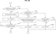
- FIGS. 6A and 6B are flowcharts illustrating an example of the processing procedure of the control method according to the present embodiment. Note that each of the processes shown in FIGS. 6A and 6B corresponds to the processes executed by the control device 140 of the surgical system 10 illustrated in FIG. 2 . Since details of the processes have already been described in the description of the functional configuration of the surgical system 10, detailed description of each process will be omitted in the following description of the processing procedure of the control method.
- Step S101 a peripheral image is acquired in the control method according to the present embodiment.
- the process indicated in Step S101 corresponds to the process of transmitting information of the peripheral image from the peripheral image acquisition camera 130 illustrated in FIG. 2 to the image processing unit 141 of the control device 140.
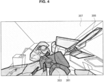
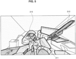
- Step S103 intrusion appropriateness regions are set. Specifically, in Step S103, for example, an intrusion prohibited region, an intrusion attention region, and an intrusion allowed region are set as intrusion appropriateness region in accordance with an instruction from the surgeon 201 given by using the GUI illustrated in FIG. 5 . Note that the process indicated in Step S103 corresponds to the process executed by the region setting unit 142 illustrated in FIG. 2 .
- Step S107 the operation mode is determined (Step S107).
- the process proceeds to Step S109, and driving of the arm unit 112 is controlled in accordance with a direct operation by the surgeon 201.
- the process of Step S109 is repeatedly executed (i.e., the driving control of the arm unit 112 continues in the manual mode) until an instruction to end control or an instruction to change the operation mode from the surgeon 201 is input.
- Step S111 driving of the arm unit 112 is controlled in accordance with a hands-free operation by the surgeon 201.
- the processes indicated in Steps S107 to Sill above correspond to the process executed by the driving control unit 146 illustrated in FIG. 2 .
- Step S111 it is determined whether the microscope unit 111 and the arm unit 112 have intruded into the intrusion prohibited region while driving of the arm unit 112 is controlled in accordance with the hands-free operation (Step S113).
- the process indicated in Step S113 corresponds to the process executed by the intrusion determination unit 144 illustrated in FIG. 2 .
- Step S115 the operation of the arm unit 112 is stopped (Step S115), and a warning that the microscope unit 111 and the arm unit 112 have intruded into the intrusion prohibited region is output (Step S117).
- the processes indicated in Steps S115 and S117 correspond to the processes executed by the driving control unit 146 and the warning control unit 147 in accordance with an instruction issued by the action instruction unit 145 illustrated in FIG. 2 .
- Step S121 the process proceeds to Step S127, and it is determined whether the microscope unit 111 and the arm unit 112 have intruded into the intrusion allowed region.
- the process indicated in Step S127 corresponds to the process executed by the intrusion determination unit 144 illustrated in FIG. 2 .
- the surgeon 201 can continue the operation of the arm unit 112 through a hands-free operation.
- the process returns to Step S111, and driving control of the arm unit 112 in accordance with the hands-free operation is continuously executed.
- the warning may be appropriately stopped through an arbitrary operation by the surgeon 201.
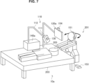
- FIG. 7 is a diagram illustrating a schematic configuration of a surgical system according to a modified example of the present embodiment.
- the surgical system 10a includes an observation device 110, a display device 120a, a peripheral image acquisition camera 130, a control device 140a, a microphone 151, a foot switch 153, and an operation recognition camera 154.
- the surgical system 10a according to the present modified example corresponds to a system configured by changing the configurations of the display device 120 and the control device 140 of the above-described surgical system 10 and not having the eyeglass-type wearable device 152 as described above.
- the marker 155 is not provided on the surgeon 201 either.
- Other matters with respect to the surgical system 10a are similar to the above-described surgical system 10. Therefore, in the following description of the surgical system 10a, matters different from the surgical system 10 will be mainly described, and detailed description of overlapping matters will be omitted.
- the display device 120a is disposed in a relatively short distance from the surgeon 201 as illustrated.
- the display device 120a is disposed in front of the eyes of the surgeon 201 above the patient bed 203.
- the display device 120a is a naked-eye 3D display, and the surgeon 201 can observe an operating site on the display device 120a in stereoscopic view without wearing a separate device such as the eyeglass-type wearable device 152.
- the operation recognition camera 154 is also disposed in a relatively short distance from the surgeon 201 in accordance with the disposition position of the display device 120a in the present modified example.
- the control device 140a can detect a line of sight of the surgeon 201 on the basis of an image captured by the operation recognition camera 154.
- the control device 140a can accurately recognize a head track of the surgeon 201 on the basis of the image captured by the operation recognition camera 154, even without the marker 155.
- control device 140a Since matters with respect to the configuration and the function of the control device 140a other than the above-described methods of recognizing a line of sight and a head track of the surgeon 201 are similar to those of the control device 140 illustrated in FIG. 2 , description thereof will be omitted.
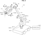
- FIG. 8 is an exterior diagram illustrating a configuration example of the observation device 110 according to the present embodiment.
- the observation device 110 has the arm unit 112 of which a base end is connected to the patient bed 203 in the schematic diagrams illustrated in FIGS. 1 and 7 , a configuration example in which a base part 5315 grounded with a floor surface, which will be described below, is provided and the base end of the arm unit 112 is connected to the base part 5315 as illustrated in FIG. 8 .
- the configuration of the observation device 110 with the arm unit 112 having six degrees of freedom with respect to movement of the microscope unit 111 is illustrated as an example.
- the arm unit 112 of the observation device 110 may be configured to have redundant degrees of freedom as described above.
- the observation device 110 has the microscope unit 111 for enlarging and observe an observation target (an operating site of the patient 205), the arm unit 112 supporting the microscope unit 111 at its tip, a base part 5315 supporting the base end of the arm unit 112, and a control device 5317 that comprehensively control operations of the observation device 110.
- the microscope unit 111 is made up of an approximately cylindrical barrel unit 5305, an imaging unit (not illustrated) provided inside the barrel unit 5305, and an operating unit 5307 provided in a partial region on the outer circumference of the barrel unit 5305.
- the aperture on the bottom end of the barrel unit 5305 is provided with a cover glass that protects the imaging unit inside. Observation light passes through the cover glass and is incident on the imaging unit inside the barrel unit 5305.
- a light source made up of a light-emitting diode (LED) or the like, for example, may also be provided inside the barrel unit 5305, and during imaging, light may be radiated from the light source onto the observation target through the cover glass.
- LED light-emitting diode
- the imaging unit is made up of an optical system that condenses observation light, and an image sensor that senses the observation light condensed by the optical system.
- the optical system is made up of a combination of multiple lenses, including a focus lens and a zoom lens, the optical characteristics of which are adjusted so that an image of the observation light is formed on the light-sensitive face of the image sensor.
- the image sensor senses and photoelectrically converts the observation light to thereby generate an image signal corresponding to the observed image.
- a sensor capable of color photography including a Bayer array, for example, is used as the image sensor.
- the image sensor may be any of various known types of image sensors, such as a complementary metal-oxide-semiconductor (CMOS) image sensor or a charge-coupled device (CCD) image sensor.
- CMOS complementary metal-oxide-semiconductor
- CCD charge-coupled device
- the imaging unit may also include a driving mechanism that moves the focus lens and the zoom lens of the optical system along the optical axis. By suitably moving the zoom lens and the focus lens with the driving mechanism, the focus distance during imaging and the magnification factor of the captured image may be adjusted.
- the imaging unit may be provided with any of various types of functions typically provided in electronic imaging microscope units, such as an auto exposure (AE) function, an auto focus (AF) function or the like.
- the imaging unit is configured to have a pair of image sensors for acquiring image signals for right eye and left eye each corresponding to stereoscopic view (3D display). Due to 3D display, the operator can ascertain the depth of a biological tissue of the operating site more accurately.
- the imaging unit is configured to be a multi-plate type, a plurality of optical systems can be provided corresponding to each of the image sensors.
- the imaging unit may be configured as a so-called single-plate imaging unit having one image sensor, or may be configured as a so-called multi-plate imaging unit having one or more image sensors.
- image signals each corresponding to R, G, and B are generated by each of the image sensors, the signals may be combined, and thereby a color image is obtained.
- the operating unit 5307 is constituted by, for example, a 4-direction lever, a switch, or the like, and is an input means that receives operation input of the surgeon 201.
- the surgeon 201 can input an instruction to change a focal distance to an observation target of an observation image and an enlargement magnification via the operating unit 5307.
- the driving mechanism of the imaging unit appropriately moves the zoom lens and the focus lens in accordance with the instruction, the focal distance and the enlargement magnification can be adjusted.
- the surgeon 201 can input an instruction to further shift the operation mode to one of an all-free mode and a locked mode, which will be described below, via the operating unit 5307.
- the operating unit 5307 it is preferable for the operating unit 5307 to be provided at a position at which the surgeon 201 can easily operate the operating unit with his or her finger, holding the barrel unit 5305 so that the surgeon 201 can operate it while moving the barrel unit 5305.
- the arm unit 112 is configured as a result of multiple links (a first link 5313a to a sixth link 5313f) being rotatably joined to each other by multiple joint units (a first joint unit 5311a to a sixth joint unit 5311f).
- the first joint unit 5311a has an approximately cylindrical shape, and on the leading end (bottom end) thereof supports the top end of the barrel unit 5305 of the microscope unit 111, so as to allow rotation about a rotation axis (first axis O 1 ) parallel to the central axis of the barrel unit 5305.
- the first joint unit 5311a may be configured so that the first axis O 1 is aligned with the optical axis of the imaging unit of the microscope unit 111. Consequently, rotating the microscope unit 111 about the first axis O 1 makes it possible to change the field of view as though rotating the captured image.
- the first link 5313a securely supports the first joint unit 5311a on the leading end thereof.
- the first link 5313a is an approximately L-shaped rod-like member, the leading edge of which extends in a direction orthogonal to the first axis O 1 , while also being connected to the first joint unit 5311a so that the end of that edge abuts the top end on the outer circumference of the first joint unit 5311a.
- the second joint unit 5311b is connected to the end of the base edge of the approximate L-shape of the first link 5313a.
- the second joint unit 5311b has an approximately cylindrical shape, and on the leading end thereof supports the base end of the first link 5313a, so as to allow rotation about a rotation axis (second axis O 2 ) orthogonal to the first axis O 1 .
- the leading end of the second link 5313b is securely connected to the base end of the second joint unit 5311b.
- the second link 5313b is an approximately L-shaped rod-like member, the leading edge of which extends in a direction orthogonal to the second axis O 2 , while the end of that edge is securely connected to the base end of the second joint unit 5311b.
- the third joint unit 5311c is connected to the base edge of the approximate L-shape of the second link 5313b.
- the third joint unit 5311c has an approximately cylindrical shape, and on the leading end thereof supports the base end of the second link 5313b, so as to allow rotation about a rotation axis (third axis O 3 ) orthogonal to both the first axis O 1 and the second axis O 2 .
- the leading end of the third link 5313c is securely connected to the base end of the third joint unit 5311c.
- the third link 5313c is configured to have an approximately cylindrical shape on the leading end side, and on the leading end of the cylindrical shape, the base end of the third joint unit 5311c is securely connected so that both have approximately the same central axis.
- the base end side of the third link 5313c has a rectangular column shape, and the fourth joint unit 5311d is connected to the end thereof.
- the fourth joint unit 5311d has an approximately cylindrical shape, and on the leading end thereof supports the base end of the third link 5313c, so as to allow rotation about a rotation axis (fourth axis O 4 ) orthogonal to the third axis O 3 .
- the leading end of the fourth link 5313d is securely connected to the base end of the fourth joint unit 5311d.
- the fourth link 5313d is a rod-like member that extends approximately linearly in a direction orthogonal to the fourth axis O 4 , while also being securely connected to the fourth joint unit 5311d so that the leading end abuts the side face of the approximately cylindrical shape of the fourth joint unit 5311d.
- the fifth joint unit 5311e is connected to the base end of the fourth link 5313d.
- the fifth joint unit 5311e has an approximately cylindrical shape, and on the leading end side thereof supports the base end of the fourth link 5313d, so as to allow rotation about a rotation axis (fifth axis O 5 ) parallel to the fourth axis O 4 .
- the leading end of the fifth link 5313e is securely connected to the base end of the fifth joint unit 5311e.
- the fourth axis O 4 and the fifth axis O 5 are rotation axes enabling the microscope unit 111 to be moved in the vertical direction.
- the height of the microscope unit 111 By rotating the configuration on the leading-end side, including the microscope unit 111, about the fourth axis O 4 and the fifth axis O 5 , the height of the microscope unit 111, or in other words the distance between the microscope unit 111 and the observation target, may be adjusted.
- the sixth joint unit 5311f has an approximately cylindrical shape, and on the leading end side thereof supports the base end of the fifth link 5313e, so as to allow rotation about a rotation axis (sixth axis O 6 ) parallel to the vertical direction.
- the leading end of the sixth link 5313f is securely connected to the base end of the sixth joint unit 5311f.
- the sixth link 5313f is a rod-like member that extends in the vertical direction, with the base end securely connected to the top face of the base unit 5315.
- the allowable rotation range of the first joint unit 5311a to the sixth joint unit 5311f is suitably set so that the microscope unit 111 is capable of desired motion. Consequently, in the arm unit 112 having the configuration described above, three degrees of translational freedom and three degrees of rotational freedom, for a total of six degrees of freedom, may be realized for the motion of the microscope unit 111. In this way, by configuring the arm unit 112 so that six degrees of freedom are realized for the motion of the microscope unit 111, it becomes possible to freely control the position and the attitude of the microscope unit 111 within the movable range of the arm unit 112. Consequently, it becomes possible to observe an operating site from any angle, and surgery may be executed more smoothly.
- the configuration of the arm unit 112 illustrated in the diagram is merely one example, and factors such as the number and the shapes (lengths) of the links constituting the arm unit 112, as well as the number and arrangement of the joint units and the directions of the rotation axes may be designed suitably so that the desired degrees of freedom may be realized.
- the arm unit 112 preferably is configured to have six degrees of freedom, but the arm unit 112 may also be configured to have more degrees of freedom (in other words, redundant degrees of freedom).
- redundant degrees of freedom exist, in the arm unit 112, it becomes possible to change the attitude of the arm unit 112 while keeping the position and the attitude of the microscope unit 111 in a locked state.
- the first joint unit 5311a to the sixth joint unit 5311f may be provided with actuators equipped with a driving mechanism such as a motor, an encoder that detects the rotation angle in each joint unit, and the like.
- a driving mechanism such as a motor, an encoder that detects the rotation angle in each joint unit, and the like.
- the control device 5317 suitable control the driving of each actuator provided for the first joint unit 5311a to the sixth joint unit 5311f, the attitude of the arm unit 112, or in other words the position and the attitude of the microscope unit 111, may be controlled.
- the control device 5317 is able to ascertain the current state of the arm unit 112 on the basis of information about the rotation angle of each joint unit detected by the encoder.
- the control device 5317 calculates a control value of each joint unit that is likely to realize movement of the microscope unit 111 in accordance with the operation by the surgeon 201 on the basis of the ascertained current state of the arm unit 112 and drives the driving mechanism of each joint unit in accordance with the control value.
- the control device 5317 appropriately controls driving of the arm unit 112 in accordance with a direct operation by the surgeon 201 through force control, and thus the position and the attitude of the microscope unit 111 are controlled as described above.
- the control device 5317 appropriately controls driving of the arm unit 112 in accordance with a hands-free operation by the surgeon 201 through position control, and thus the position and the attitude of the microscope unit 111 are controlled.
- Such a brake operation may be performed in response to operation performed by the surgeon 201 via the operating unit 5307 described above.
- the surgeon 201 When the user wants to move the position and the attitude of the microscope unit 111, the surgeon 201 operates the operating unit 5307 to release the brake on each joint unit. As a result, the operation mode of the arm unit 112 switches to a mode allowing each joint unit to be rotated freely (all-free mode). Meanwhile, when the surgeon 201 wants to lock the position and the attitude of the microscope unit 111, the user operates the operating unit 5307 to apply the brake on each joint unit. As a result, the operation mode of the arm unit 112 switches to a mode in which the rotation of each joint unit is restrained (locked mode).
- the control device 5317 controls operations of the observation device 110.
- the control device 5317 controls driving of the arm unit 112 by causing actuators of the first joint unit part 5311a to the sixth joint unit part 5311f to operate in accordance with an operation of the surgeon 201.
- the control device 5317 changes the operation mode of the arm unit 112 between the all-free mode and the locked mode.
- the control device 5317 adjusts, for example, photographing conditions (a focal distance and an enlargement magnification) of the imaging unit of the microscope unit 111 of the observation device 110.
- control device 5317 performs, for example, various kinds of signal processing on an image signal acquired by the imaging unit of the microscope unit 111 of the observation device 110, and causes the display device 120 (not illustrated in FIG. 8 ) to display an image of the operating site on the basis of the image data.
- the communication between the control device 5317 and the microscope unit 111, as well as the communication between the control device 5317 and the first joint unit 5311a to the sixth joint unit 5311f, may be wired communication or wireless communication.
- wired communication communication using electrical signals may be conducted, or optical communication may be conducted.
- the transmission cable used for wired communication may be configured as an electrical signal cable, optical fiber, or a composite cable of the two, in accordance with the communication method.
- wireless communication it is no longer necessary to lay down a transmission cable inside the operating room, and thus a situation in which the movement of medical staff inside the operating room is impeded by such a transmission cable may be resolved.
- the control device 5317 may be a processor such as a central processing unit (CPU) or a graphics processing unit (GPU), a control board on which a processor and a storage element such as a memory are both mounted, or the like.
- a processor such as a central processing unit (CPU) or a graphics processing unit (GPU)
- GPU graphics processing unit
- the various functions described above may be realized.
- the control device 5317 is provided as a separate device from the observation device 110, but the control device 5317 may also be unified with the observation device 110, such as by being installed inside the base unit 5315 of the observation device 110, for example.
- the control device 5317 may be made up of multiple devices.
- control board or the like in the microscope unit 5303 and each of the first joint unit 5311a to the sixth joint unit 5311f of the arm unit 5309, and communicably connecting these control boards to each other functions similar to the control device 5317 may be realized.
- control device 5317 can be the same as the control devices 140 of the above-described surgical systems 10 and 10a. That is, the control device 5317 may have similar functions to those of the control devices 140, control operations of the observation device 110, and comprehensively control operations of the surgical systems 10 and 10a.
- the technology according to the present disclosure is not limited thereto.
- the technology according to the present disclosure may be applied to a surgical system in which an arm unit is operated in a master-slave scheme. Since an operator remotely operates the arm unit in the master-slave scheme, the operator can operate the arm unit without directly viewing the arm unit, similarly to the hands-free operation. Thus, since the technology according to the present disclosure is applied, similar effects can be obtained.
- the technology according to the present disclosure can be preferably applied to the surgical system in which an operator operates an arm unit without being in contact with the arm unit.
- the intrusion hindering action may be an action that can hinder intrusion of the arm unit into the intrusion appropriateness region, and a type thereof is not limited.
- the intrusion hindering action for example, only one of the operation of the arm unit to avoid intrusion into the intrusion appropriateness region and output of a warning may be performed.
- various actions giving an alert for intrusion of the arm unit into the intrusion appropriateness region to the operator may be performed as the intrusion hindering action.
- an action giving an alert for intrusion of the arm unit into the intrusion appropriateness region to the operator for example, an action of gradually decreasing an operation speed of the arm unit as the arm unit gets closer to the intrusion appropriateness region or the like is considered. Since the operation speed of the microscope unit 111 decreases if the operation speed of the arm unit decreases, a speed of movement of the visual field with respect to the image of the operating site viewed by the operator becomes lower accordingly. The operator can recognize that the arm unit is getting closer to the intrusion appropriateness region since the speed of movement of the visual field with respect to the image of the operating site becomes lower. In addition, as the intrusion hindering action, every action used as feedback to an operator when any alert is generally given to the operator in an operation of a support arm device may be employed.
Landscapes
- Engineering & Computer Science (AREA)
- Health & Medical Sciences (AREA)
- Surgery (AREA)
- Life Sciences & Earth Sciences (AREA)
- Robotics (AREA)
- General Health & Medical Sciences (AREA)
- Medical Informatics (AREA)
- Biomedical Technology (AREA)
- Veterinary Medicine (AREA)
- Public Health (AREA)
- Animal Behavior & Ethology (AREA)
- Molecular Biology (AREA)
- Nuclear Medicine, Radiotherapy & Molecular Imaging (AREA)
- Heart & Thoracic Surgery (AREA)
- Mechanical Engineering (AREA)
- Physics & Mathematics (AREA)
- Pathology (AREA)
- Oral & Maxillofacial Surgery (AREA)
- Chemical & Material Sciences (AREA)
- Optics & Photonics (AREA)
- Analytical Chemistry (AREA)
- General Physics & Mathematics (AREA)
- Multimedia (AREA)
- Manipulator (AREA)
Claims (15)
- Steuerungsvorrichtung (140, 140a), umfassend:eine Antriebssteuereinheit (146), die zum Steuern des Antriebs einer Armeinheit konfiguriert ist, die ein medizinisches Instrument trägt;eine Bereichsfestlegungseinheit (142), die konfiguriert ist, um gemäß einem Bereichsauswahlvorgang durch einen Benutzer über eine manuelle Eingabevorrichtung (170) mindestens einen Bereich aus einer Vielzahl von Bereichen in einem Peripheriebild als Eindringungsverbotsbereich festzulegen, um den mindestens einen Bereich in dem Peripheriebild über eine grafische Benutzeroberfläche auszuwählen, wobei das Peripheriebild die Armeinheit und das medizinische Instrument und eine Vielzahl von Objekten einschließt und jeder Bereich des Peripheriebildes eines der Vielzahl von Objekten einschließt und einem Abschnitt eines Raums entspricht, wobei der Eindringungsverbotsbereich einem Abschnitt des Raums entspricht, für den das Eindringen des medizinischen Instruments oder der Armeinheit in einen Bewegungsbereich der Armeinheit verboten ist ;eine Eindringungsbestimmungseinheit (144), die konfiguriert ist, um ein Vorhandensein oder Nichtvorhandensein des medizinischen Instruments oder der Armeinheit innerhalb eines Abstands von dem Eindringungsverbotsbereichs zu bestimmen, der kleiner oder gleich einem vorgegebenen Schwellenwert ist, wenn die Antriebssteuereinheit den Antrieb der Armeinheit gemäß einer berührungslosen Bedienung durch einen Benutzer in Bezug auf die Armeinheit steuert ; undeine Maßnahmenanweisungseinheit (145), die konfiguriert ist, um gemäß einem Bestimmungsergebnis der Eindringungsbestimmungseinheit eine Eindringungsverhinderungsmaßnahme zum Verhindern des Eindringens des medizinischen Instruments oder der Armeinheit in den Eindringungsverbotsbereich zu bewirken.
- Steuerungsvorrichtung nach Anspruch 1,
wobei die Eindringungsverhinderungsmaßnahme mindestens eines von einer Bedienung der Armeinheit, um das Eindringen in den Eindringungseignungsbereich zu vermeiden, oder einer Ausgabe einer Warnung ist. - Steuerungsvorrichtung nach Anspruch 1,
wobei die Bereichsfestlegungseinheit konfiguriert ist, um mindestens einen Bereich aus der Vielzahl von Bereichen in dem Peripheriebild als Eindringungsvorsichtsbereich festzulegen, d. h. einen Bereich, in den das medizinische Instrument oder die Armeinheit innerhalb des Bewegungsbereichs der Armeinheit teilweise eindringen darf. - Steuerungsvorrichtung nach Anspruch 1,
wobei die Bereichsfestlegungseinheit konfiguriert ist, um mindestens einen Bereich aus der Vielzahl von Bereichen in dem Peripheriebild als Eindringungszulässigkeitsbereich festzulegen, d. h. einen Bereich, in den das medizinische Instrument oder die Armeinheit innerhalb des Bewegungsbereichs der Armeinheit eindringen darf. - Steuerungsvorrichtung nach Anspruch 1,wobei das Peripheriebild einen Zustand innerhalb eines Operationssaals einschließt undder Eindringungsverbotsbereich einen Bereich einschließt, in dem sich mindestens ein Patient oder eine chirurgische Einrichtung in der Nähe eines Patientenbetts befindet.
- Steuerungsvorrichtung nach Anspruch 3,wobei das Peripheriebild einen Zustand innerhalb eines Operationssaals einschließt undder Eindringungsvorsichtsbereich einen Bereich einschließt, in dem mindestens eines von einem in dem Operationssaal aufgehängten Kabel oder einem in dem Operationssaal aufgehängten Tuch vorhanden ist.
- Steuerungsvorrichtung nach Anspruch 4,wobei das Peripheriebild einen Zustand innerhalb eines Operationssaals einschließt undder Eindringungszulässigkeitsbereich einen Bereich einschließt, in dem medizinisches Personal anwesend ist.
- Steuerungsvorrichtung nach Anspruch 1,
wobei in einem Fall, in dem die Eindringbestimmungseinheit bestimmt, dass das medizinische Instrument oder die Armeinheit in den Eindringungsverbotsbereich eingedrungen ist, die Maßnahmenanweisungseinheit eine Anweisung zum Stoppen einer Bedienung der Armeinheit und eine Anweisung zum Ausgeben einer Warnung ausgibt. - Steuerungsvorrichtung nach Anspruch 3,wobei die Armeinheit so konfiguriert ist, dass sie einen redundanten Freiheitsgrad in Bezug auf die Bewegung des medizinischen Instruments aufweist, undin einem Fall, in dem die Eindringbestimmungseinheit bestimmt, dass das medizinische Instrument oder die Armeinheit in den Eindringungsvorsichtsbereich eingedrungen ist, die Maßnahmenanweisungseinheit eine Anweisung, die Armeinheit zu veranlassen, so zu arbeiten, dass die Armeinheit nicht in den Eindringungsvorsichtsbereich eindringt, während eine Position und eine Haltung des medizinischen Instruments aufrechterhalten werden, sowie eine Anweisung erteilt, eine Warnung auszugeben.
- Steuerungsvorrichtung nach Anspruch 4,
wobei in einem Fall, in dem die Eindringbestimmungseinheit bestimmt, dass das medizinische Instrument oder die Armeinheit in den Eindringungszulässigkeitsbereich eingedrungen ist, die Maßnahmenanweisungseinheit eine Anweisung zum Ausgeben einer Warnung erteilt. - Steuerungsvorrichtung nach Anspruch 1,wobei die berührungslose Bedienung in Bezug auf die Armeinheit durch den Benutzer eine freihändige Bedienung durch den Benutzer einschließt, der die Armeinheit bedient, ohne seine Hände zu verwenden, unddie freihändige Bedienung eine Bedienung über mindestens eines von einer Stimme, einer Sichtlinie, einer Kopfbewegung, einer Geste oder einem Fußschalter einschließt.
- Steuerungsvorrichtung nach Anspruch 1,
wobei eine berührungslose Bedienung in Bezug auf die Armeinheit durch den Benutzer eine Bedienung der Armeinheit in einem Master-Slave-Schema einschließt. - Steuerungsvorrichtung nach Anspruch 1,
wobei das medizinische Instrument eine elektronische Bildgebungsmikroskopeinheit ist, die ein Beobachtungsziel vergrößert und fotografiert. - Steuerungsvorrichtung, umfassend:Festlegen, durch einen Prozessor, mindestens eines Bereichs aus einer Vielzahl von Bereichen in einem Peripheriebild als Eindringungsverbotsbereich gemäß einem Bereichsauswahlvorgang durch einen Benutzer über eine manuelle Eingabevorrichtung, der den mindestens einen Bereich in dem Peripheriebild über eine grafische Benutzeroberfläche auswählt, wobei das Peripheriebild eine Armeinheit, ein durch die Armeinheit getragenes medizinisches Instrument und eine Vielzahl von Objekten einschließt, wobei jeder Bereich des Peripheriebildes eines der Vielzahl von Objekten einschließt und einem Abschnitt eines Raums entspricht, wobei der Eindringungsverbotsbereich einem Abschnitt des Raums entspricht, für den das Eindringen des medizinischen Instruments oder der Armeinheit in einen Bewegungsbereich der Armeinheit verboten ist ;Bestimmen eines Vorhandenseins oder Nichtvorhandenseins einer Eindringung des medizinischen Instruments oder der Armeinheit innerhalb eines Abstands von dem Eindringungsverbotsbereich, der kleiner oder gleich einem vorgegebenen Schwellenwert ist, wenn der Antrieb der Armeinheit gemäß einer berührungslosen Bedienung durch einen Benutzer in Bezug auf die Armeinheit gesteuert wird ; undVeranlassen, dass eine Eindringungsverhinderungsmaßnahme zum Verhindern des Eindringens des medizinischen Instruments oder der Armeinheit in den Eindringungsverbotsbereich gemäß einem Ergebnis der Bestimmung des Vorhandenseins oder Nichtvorhandenseins des Eindringens des medizinischen Instruments oder der Armeinheit in den Eindringeignungsbereich ausgeführt wird.
- Chirurgisches System (10, 10a), umfassend:die Steuerungsvorrichtung nach Anspruch 1, wobei das medizinische Instrument eine Mikroskopeinheit ist ;die Mikroskopeinheit so konfiguriert ist, dass sie durch die Armeinheit getragen wird und eines Operationsstelle vergrößert und fotografiert ;eine Anzeigevorrichtung (120, 120a), die konfiguriert ist, um ein von der Mikroskopeinheit fotografiertes Bild der Operationsstelle anzuzeigen ; undeine Peripheriebildaufnahmekamera (130), die konfiguriert ist, um das Peripheriebild aufzunehmen, das einen Peripheriezustand der Mikroskopeinheit oder der Armeinheit fotografiert.
Applications Claiming Priority (2)
| Application Number | Priority Date | Filing Date | Title |
|---|---|---|---|
| JP2016090167 | 2016-04-28 | ||
| PCT/JP2017/008830 WO2017187795A1 (ja) | 2016-04-28 | 2017-03-06 | 制御装置、制御方法及び手術システム |
Publications (3)
| Publication Number | Publication Date |
|---|---|
| EP3449859A1 EP3449859A1 (de) | 2019-03-06 |
| EP3449859A4 EP3449859A4 (de) | 2019-05-15 |
| EP3449859B1 true EP3449859B1 (de) | 2024-07-03 |
Family
ID=60161516
Family Applications (1)
| Application Number | Title | Priority Date | Filing Date |
|---|---|---|---|
| EP17789084.5A Active EP3449859B1 (de) | 2016-04-28 | 2017-03-06 | Steuerungsvorrichtung, steuerungsverfahren und chirurgisches system |
Country Status (4)
| Country | Link |
|---|---|
| US (1) | US11278369B2 (de) |
| EP (1) | EP3449859B1 (de) |
| JP (1) | JP6939778B2 (de) |
| WO (1) | WO2017187795A1 (de) |
Families Citing this family (19)
| Publication number | Priority date | Publication date | Assignee | Title |
|---|---|---|---|---|
| JP6748088B2 (ja) | 2015-02-25 | 2020-08-26 | マコ サージカル コーポレーション | 外科手術中の追跡中断を低減するナビゲーションシステム及び方法 |
| JP6944939B2 (ja) | 2015-12-31 | 2021-10-06 | ストライカー・コーポレイション | 仮想オブジェクトにより規定される患者の標的部位に対して外科手術を行うシステムおよび方法 |
| WO2018165047A1 (en) | 2017-03-06 | 2018-09-13 | Intuitive Surgical Operations, Inc. | Systems and methods for entering and exiting a teleoperational state |
| WO2018204612A1 (en) * | 2017-05-03 | 2018-11-08 | Lsi Solutions, Inc. | Surgical equipment holder |
| EP3600125B1 (de) | 2017-05-03 | 2024-09-11 | LSI Solutions, Inc. | Halter für chirurgische ausrüstung |
| DE102017011130B4 (de) * | 2017-12-01 | 2021-03-04 | Kuka Deutschland Gmbh | Verfahren und System zum Steuern eines Roboters |
| US11625107B2 (en) * | 2019-06-27 | 2023-04-11 | Intuitive Surgical Operations, Inc. | System and method for motion mode management |
| EP3993725A1 (de) | 2019-07-03 | 2022-05-11 | Stryker Corporation | Verfahren zur vermeidung von hindernissen für die chirurgische navigation |
| US11071601B2 (en) | 2019-11-11 | 2021-07-27 | Procept Biorobotics Corporation | Surgical probes for tissue resection with robotic arms |
| KR102315803B1 (ko) * | 2019-12-16 | 2021-10-21 | 쓰리디메디비젼 주식회사 | 의료용 카메라의 거치대 |
| GB2624133B (en) * | 2020-02-25 | 2024-12-25 | Cmr Surgical Ltd | Controlling movement of a surgical robot arm |
| JP7546367B2 (ja) * | 2020-03-17 | 2024-09-06 | ソニー・オリンパスメディカルソリューションズ株式会社 | 制御装置および医療用観察システム |
| US11096753B1 (en) * | 2020-06-26 | 2021-08-24 | Procept Biorobotics Corporation | Systems and methods for defining and modifying range of motion of probe used in patient treatment |
| CN115802978A (zh) * | 2020-07-09 | 2023-03-14 | 索尼集团公司 | 医疗臂装置 |
| WO2022119763A1 (en) * | 2020-12-01 | 2022-06-09 | Intuitive Surgical Operations, Inc. | Systems and methods for planning a medical environment |
| DE102021102274A1 (de) * | 2021-02-01 | 2022-08-04 | B. Braun New Ventures GmbH | Chirurgisches Assistenzsystem mit Operationsmikroskop und Kamera und Darstellungsverfahren |
| JP7742229B2 (ja) * | 2021-02-05 | 2025-09-19 | 川崎重工業株式会社 | 手術支援ロボット、手術支援システムおよびプログラム |
| JP2024513204A (ja) * | 2021-03-31 | 2024-03-22 | ムーン サージカル エスアエス | 腹腔鏡下外科手術を実施するための外科手術用器具と併用するための協調操作式外科手術用システム |
| CN115721417B (zh) * | 2022-09-09 | 2024-01-30 | 苏州铸正机器人有限公司 | 一种手术机器人末端位姿全视野测量装置及方法 |
Family Cites Families (19)
| Publication number | Priority date | Publication date | Assignee | Title |
|---|---|---|---|---|
| US6963792B1 (en) * | 1992-01-21 | 2005-11-08 | Sri International | Surgical method |
| US7084867B1 (en) * | 1999-04-02 | 2006-08-01 | Massachusetts Institute Of Technology | Haptic interface system for collision detection and applications therefore |
| US7084869B2 (en) * | 2000-03-31 | 2006-08-01 | Massachusetts Institute Of Technology | Methods and apparatus for detecting and correcting penetration between objects |
| CA2437286C (en) * | 2002-08-13 | 2008-04-29 | Garnette Roy Sutherland | Microsurgical robot system |
| JP2004223128A (ja) | 2003-01-27 | 2004-08-12 | Hitachi Ltd | 医療行為支援装置および方法 |
| JP2005014108A (ja) | 2003-06-23 | 2005-01-20 | Honda Motor Co Ltd | 多関節ロボットの干渉回避方法 |
| US20090278915A1 (en) * | 2006-02-08 | 2009-11-12 | Oblong Industries, Inc. | Gesture-Based Control System For Vehicle Interfaces |
| DE102008041602B4 (de) * | 2008-08-27 | 2015-07-30 | Deutsches Zentrum für Luft- und Raumfahrt e.V. | Roboter und Verfahren zum Steuern eines Roboters |
| JP5571432B2 (ja) | 2010-03-30 | 2014-08-13 | カール シュトルツ ゲゼルシャフト ミット ベシュレンクテル ハフツング ウント コンパニー コマンディートゲゼルシャフト | 医療用ロボットシステム |
| KR20150058250A (ko) * | 2012-08-24 | 2015-05-28 | 유니버시티 오브 휴스턴 | 로봇 장치 및 영상 안내 및 로봇 지원 수술을 위한 시스템 |
| US20140320392A1 (en) * | 2013-01-24 | 2014-10-30 | University Of Washington Through Its Center For Commercialization | Virtual Fixtures for Improved Performance in Human/Autonomous Manipulation Tasks |
| CA2897873A1 (en) * | 2013-03-13 | 2014-10-09 | Stryker Corporation | Systems and methods for establishing virtual constraint boundaries |
| US9827054B2 (en) * | 2014-03-14 | 2017-11-28 | Synaptive Medical (Barbados) Inc. | Intelligent positioning system and methods therefore |
| WO2015008470A2 (en) | 2013-07-16 | 2015-01-22 | Seiko Epson Corporation | Information processing apparatus, information processing method, and information processing system |
| JP6311393B2 (ja) | 2014-03-28 | 2018-04-18 | セイコーエプソン株式会社 | 情報処理装置、情報処理方法、および、情報処理システム |
| DE102013012397B4 (de) * | 2013-07-26 | 2018-05-24 | Rg Mechatronics Gmbh | OP-Robotersystem |
| KR102379623B1 (ko) * | 2014-02-05 | 2022-03-29 | 인튜어티브 서지컬 오퍼레이션즈 인코포레이티드 | 동적 가상 충돌 객체를 위한 시스템 및 방법 |
| EP3112096B1 (de) | 2014-02-28 | 2020-10-14 | Sony Corporation | Roboterarmvorrichtung, kalibrierungsverfahren und programm |
| US10387021B2 (en) * | 2014-07-31 | 2019-08-20 | Restoration Robotics, Inc. | Robotic hair transplantation system with touchscreen interface for controlling movement of tool |
-
2017
- 2017-03-06 US US16/092,235 patent/US11278369B2/en active Active
- 2017-03-06 EP EP17789084.5A patent/EP3449859B1/de active Active
- 2017-03-06 JP JP2018514171A patent/JP6939778B2/ja active Active
- 2017-03-06 WO PCT/JP2017/008830 patent/WO2017187795A1/ja not_active Ceased
Also Published As
| Publication number | Publication date |
|---|---|
| JPWO2017187795A1 (ja) | 2019-03-28 |
| US20190328479A1 (en) | 2019-10-31 |
| EP3449859A4 (de) | 2019-05-15 |
| US11278369B2 (en) | 2022-03-22 |
| WO2017187795A1 (ja) | 2017-11-02 |
| EP3449859A1 (de) | 2019-03-06 |
| JP6939778B2 (ja) | 2021-09-22 |
Similar Documents
| Publication | Publication Date | Title |
|---|---|---|
| EP3449859B1 (de) | Steuerungsvorrichtung, steuerungsverfahren und chirurgisches system | |
| US11730365B2 (en) | Control device, control method, and microscope device for operation | |
| JP7480477B2 (ja) | 医療用観察システム、制御装置及び制御方法 | |
| US20180263710A1 (en) | Medical imaging apparatus and surgical navigation system | |
| CN111278344B (zh) | 手术臂系统和手术臂控制系统 | |
| CN111163675B (zh) | 医疗保持设备、医疗臂系统及悬垂安装机构 | |
| JP2018075121A (ja) | 医療用支持アーム装置 | |
| JP7800010B2 (ja) | 医療用アーム制御システム、医療用アーム制御方法、及びプログラム | |
| US11638000B2 (en) | Medical observation apparatus | |
| US11510751B2 (en) | Medical observation apparatus | |
| WO2018088113A1 (ja) | 関節駆動用アクチュエータ及び医療用システム | |
| WO2017169650A1 (ja) | 医療用観察装置、映像移動補正方法及び医療用観察システム | |
| EP3603562B1 (de) | Vorrichtung zur medizinischen beobachtung und beobachtungsfeldkorrekturverfahren | |
| JPWO2018216302A1 (ja) | 医療用観察装置、処理方法、および医療用観察システム | |
| US11648082B2 (en) | Medical holding device, and medical observation device | |
| US20200093545A1 (en) | Control apparatus, control method, and medical observation system | |
| US20240155241A1 (en) | Medical observation system, information processing device, and information processing method | |
| US20220322919A1 (en) | Medical support arm and medical system | |
| WO2018043205A1 (ja) | 医療用画像処理装置、医療用画像処理方法、プログラム |
Legal Events
| Date | Code | Title | Description |
|---|---|---|---|
| STAA | Information on the status of an ep patent application or granted ep patent |
Free format text: STATUS: THE INTERNATIONAL PUBLICATION HAS BEEN MADE |
|
| PUAI | Public reference made under article 153(3) epc to a published international application that has entered the european phase |
Free format text: ORIGINAL CODE: 0009012 |
|
| STAA | Information on the status of an ep patent application or granted ep patent |
Free format text: STATUS: REQUEST FOR EXAMINATION WAS MADE |
|
| 17P | Request for examination filed |
Effective date: 20181015 |
|
| AK | Designated contracting states |
Kind code of ref document: A1 Designated state(s): AL AT BE BG CH CY CZ DE DK EE ES FI FR GB GR HR HU IE IS IT LI LT LU LV MC MK MT NL NO PL PT RO RS SE SI SK SM TR |
|
| AX | Request for extension of the european patent |
Extension state: BA ME |
|
| A4 | Supplementary search report drawn up and despatched |
Effective date: 20190415 |
|
| RIC1 | Information provided on ipc code assigned before grant |
Ipc: A61B 34/35 20160101AFI20190409BHEP Ipc: B25J 3/00 20060101ALI20190409BHEP Ipc: A61B 34/30 20160101ALI20190409BHEP Ipc: A61B 34/00 20160101ALI20190409BHEP Ipc: B25J 9/16 20060101ALI20190409BHEP Ipc: B25J 19/06 20060101ALI20190409BHEP Ipc: A61B 90/25 20160101ALI20190409BHEP |
|
| DAV | Request for validation of the european patent (deleted) | ||
| DAX | Request for extension of the european patent (deleted) | ||
| RAP3 | Party data changed (applicant data changed or rights of an application transferred) |
Owner name: SONY GROUP CORPORATION |
|
| STAA | Information on the status of an ep patent application or granted ep patent |
Free format text: STATUS: EXAMINATION IS IN PROGRESS |
|
| 17Q | First examination report despatched |
Effective date: 20210908 |
|
| GRAP | Despatch of communication of intention to grant a patent |
Free format text: ORIGINAL CODE: EPIDOSNIGR1 |
|
| STAA | Information on the status of an ep patent application or granted ep patent |
Free format text: STATUS: GRANT OF PATENT IS INTENDED |
|
| INTG | Intention to grant announced |
Effective date: 20240206 |
|
| GRAS | Grant fee paid |
Free format text: ORIGINAL CODE: EPIDOSNIGR3 |
|
| GRAA | (expected) grant |
Free format text: ORIGINAL CODE: 0009210 |
|
| STAA | Information on the status of an ep patent application or granted ep patent |
Free format text: STATUS: THE PATENT HAS BEEN GRANTED |
|
| P01 | Opt-out of the competence of the unified patent court (upc) registered |
Effective date: 20240521 |
|
| AK | Designated contracting states |
Kind code of ref document: B1 Designated state(s): AL AT BE BG CH CY CZ DE DK EE ES FI FR GB GR HR HU IE IS IT LI LT LU LV MC MK MT NL NO PL PT RO RS SE SI SK SM TR |
|
| REG | Reference to a national code |
Ref country code: CH Ref legal event code: EP |
|
| REG | Reference to a national code |
Ref country code: DE Ref legal event code: R096 Ref document number: 602017083005 Country of ref document: DE |
|
| REG | Reference to a national code |
Ref country code: LT Ref legal event code: MG9D |
|
| REG | Reference to a national code |
Ref country code: NL Ref legal event code: MP Effective date: 20240703 |
|
| PG25 | Lapsed in a contracting state [announced via postgrant information from national office to epo] |
Ref country code: PT Free format text: LAPSE BECAUSE OF FAILURE TO SUBMIT A TRANSLATION OF THE DESCRIPTION OR TO PAY THE FEE WITHIN THE PRESCRIBED TIME-LIMIT Effective date: 20241104 |
|
| REG | Reference to a national code |
Ref country code: AT Ref legal event code: MK05 Ref document number: 1699009 Country of ref document: AT Kind code of ref document: T Effective date: 20240703 |
|
| PG25 | Lapsed in a contracting state [announced via postgrant information from national office to epo] |
Ref country code: NL Free format text: LAPSE BECAUSE OF FAILURE TO SUBMIT A TRANSLATION OF THE DESCRIPTION OR TO PAY THE FEE WITHIN THE PRESCRIBED TIME-LIMIT Effective date: 20240703 |
|
| PG25 | Lapsed in a contracting state [announced via postgrant information from national office to epo] |
Ref country code: PT Free format text: LAPSE BECAUSE OF FAILURE TO SUBMIT A TRANSLATION OF THE DESCRIPTION OR TO PAY THE FEE WITHIN THE PRESCRIBED TIME-LIMIT Effective date: 20241104 Ref country code: NL Free format text: LAPSE BECAUSE OF FAILURE TO SUBMIT A TRANSLATION OF THE DESCRIPTION OR TO PAY THE FEE WITHIN THE PRESCRIBED TIME-LIMIT Effective date: 20240703 |
|
| PG25 | Lapsed in a contracting state [announced via postgrant information from national office to epo] |
Ref country code: NO Free format text: LAPSE BECAUSE OF FAILURE TO SUBMIT A TRANSLATION OF THE DESCRIPTION OR TO PAY THE FEE WITHIN THE PRESCRIBED TIME-LIMIT Effective date: 20241003 |
|
| PG25 | Lapsed in a contracting state [announced via postgrant information from national office to epo] |
Ref country code: GR Free format text: LAPSE BECAUSE OF FAILURE TO SUBMIT A TRANSLATION OF THE DESCRIPTION OR TO PAY THE FEE WITHIN THE PRESCRIBED TIME-LIMIT Effective date: 20241004 Ref country code: FI Free format text: LAPSE BECAUSE OF FAILURE TO SUBMIT A TRANSLATION OF THE DESCRIPTION OR TO PAY THE FEE WITHIN THE PRESCRIBED TIME-LIMIT Effective date: 20240703 Ref country code: PL Free format text: LAPSE BECAUSE OF FAILURE TO SUBMIT A TRANSLATION OF THE DESCRIPTION OR TO PAY THE FEE WITHIN THE PRESCRIBED TIME-LIMIT Effective date: 20240703 |
|
| PG25 | Lapsed in a contracting state [announced via postgrant information from national office to epo] |
Ref country code: BG Free format text: LAPSE BECAUSE OF FAILURE TO SUBMIT A TRANSLATION OF THE DESCRIPTION OR TO PAY THE FEE WITHIN THE PRESCRIBED TIME-LIMIT Effective date: 20240703 |
|
| PG25 | Lapsed in a contracting state [announced via postgrant information from national office to epo] |
Ref country code: LV Free format text: LAPSE BECAUSE OF FAILURE TO SUBMIT A TRANSLATION OF THE DESCRIPTION OR TO PAY THE FEE WITHIN THE PRESCRIBED TIME-LIMIT Effective date: 20240703 |
|
| PG25 | Lapsed in a contracting state [announced via postgrant information from national office to epo] |
Ref country code: IS Free format text: LAPSE BECAUSE OF FAILURE TO SUBMIT A TRANSLATION OF THE DESCRIPTION OR TO PAY THE FEE WITHIN THE PRESCRIBED TIME-LIMIT Effective date: 20241103 Ref country code: AT Free format text: LAPSE BECAUSE OF FAILURE TO SUBMIT A TRANSLATION OF THE DESCRIPTION OR TO PAY THE FEE WITHIN THE PRESCRIBED TIME-LIMIT Effective date: 20240703 |
|
| PG25 | Lapsed in a contracting state [announced via postgrant information from national office to epo] |
Ref country code: CZ Free format text: LAPSE BECAUSE OF FAILURE TO SUBMIT A TRANSLATION OF THE DESCRIPTION OR TO PAY THE FEE WITHIN THE PRESCRIBED TIME-LIMIT Effective date: 20240703 Ref country code: HR Free format text: LAPSE BECAUSE OF FAILURE TO SUBMIT A TRANSLATION OF THE DESCRIPTION OR TO PAY THE FEE WITHIN THE PRESCRIBED TIME-LIMIT Effective date: 20240703 |
|
| PG25 | Lapsed in a contracting state [announced via postgrant information from national office to epo] |
Ref country code: ES Free format text: LAPSE BECAUSE OF FAILURE TO SUBMIT A TRANSLATION OF THE DESCRIPTION OR TO PAY THE FEE WITHIN THE PRESCRIBED TIME-LIMIT Effective date: 20240703 Ref country code: RS Free format text: LAPSE BECAUSE OF FAILURE TO SUBMIT A TRANSLATION OF THE DESCRIPTION OR TO PAY THE FEE WITHIN THE PRESCRIBED TIME-LIMIT Effective date: 20241003 |
|
| PG25 | Lapsed in a contracting state [announced via postgrant information from national office to epo] |
Ref country code: RS Free format text: LAPSE BECAUSE OF FAILURE TO SUBMIT A TRANSLATION OF THE DESCRIPTION OR TO PAY THE FEE WITHIN THE PRESCRIBED TIME-LIMIT Effective date: 20241003 Ref country code: PL Free format text: LAPSE BECAUSE OF FAILURE TO SUBMIT A TRANSLATION OF THE DESCRIPTION OR TO PAY THE FEE WITHIN THE PRESCRIBED TIME-LIMIT Effective date: 20240703 Ref country code: NO Free format text: LAPSE BECAUSE OF FAILURE TO SUBMIT A TRANSLATION OF THE DESCRIPTION OR TO PAY THE FEE WITHIN THE PRESCRIBED TIME-LIMIT Effective date: 20241003 Ref country code: LV Free format text: LAPSE BECAUSE OF FAILURE TO SUBMIT A TRANSLATION OF THE DESCRIPTION OR TO PAY THE FEE WITHIN THE PRESCRIBED TIME-LIMIT Effective date: 20240703 Ref country code: IS Free format text: LAPSE BECAUSE OF FAILURE TO SUBMIT A TRANSLATION OF THE DESCRIPTION OR TO PAY THE FEE WITHIN THE PRESCRIBED TIME-LIMIT Effective date: 20241103 Ref country code: HR Free format text: LAPSE BECAUSE OF FAILURE TO SUBMIT A TRANSLATION OF THE DESCRIPTION OR TO PAY THE FEE WITHIN THE PRESCRIBED TIME-LIMIT Effective date: 20240703 Ref country code: GR Free format text: LAPSE BECAUSE OF FAILURE TO SUBMIT A TRANSLATION OF THE DESCRIPTION OR TO PAY THE FEE WITHIN THE PRESCRIBED TIME-LIMIT Effective date: 20241004 Ref country code: FI Free format text: LAPSE BECAUSE OF FAILURE TO SUBMIT A TRANSLATION OF THE DESCRIPTION OR TO PAY THE FEE WITHIN THE PRESCRIBED TIME-LIMIT Effective date: 20240703 Ref country code: ES Free format text: LAPSE BECAUSE OF FAILURE TO SUBMIT A TRANSLATION OF THE DESCRIPTION OR TO PAY THE FEE WITHIN THE PRESCRIBED TIME-LIMIT Effective date: 20240703 Ref country code: CZ Free format text: LAPSE BECAUSE OF FAILURE TO SUBMIT A TRANSLATION OF THE DESCRIPTION OR TO PAY THE FEE WITHIN THE PRESCRIBED TIME-LIMIT Effective date: 20240703 Ref country code: BG Free format text: LAPSE BECAUSE OF FAILURE TO SUBMIT A TRANSLATION OF THE DESCRIPTION OR TO PAY THE FEE WITHIN THE PRESCRIBED TIME-LIMIT Effective date: 20240703 Ref country code: AT Free format text: LAPSE BECAUSE OF FAILURE TO SUBMIT A TRANSLATION OF THE DESCRIPTION OR TO PAY THE FEE WITHIN THE PRESCRIBED TIME-LIMIT Effective date: 20240703 |
|
| REG | Reference to a national code |
Ref country code: DE Ref legal event code: R097 Ref document number: 602017083005 Country of ref document: DE |
|
| PG25 | Lapsed in a contracting state [announced via postgrant information from national office to epo] |
Ref country code: DK Free format text: LAPSE BECAUSE OF FAILURE TO SUBMIT A TRANSLATION OF THE DESCRIPTION OR TO PAY THE FEE WITHIN THE PRESCRIBED TIME-LIMIT Effective date: 20240703 Ref country code: RO Free format text: LAPSE BECAUSE OF FAILURE TO SUBMIT A TRANSLATION OF THE DESCRIPTION OR TO PAY THE FEE WITHIN THE PRESCRIBED TIME-LIMIT Effective date: 20240703 Ref country code: SM Free format text: LAPSE BECAUSE OF FAILURE TO SUBMIT A TRANSLATION OF THE DESCRIPTION OR TO PAY THE FEE WITHIN THE PRESCRIBED TIME-LIMIT Effective date: 20240703 |
|
| PG25 | Lapsed in a contracting state [announced via postgrant information from national office to epo] |
Ref country code: EE Free format text: LAPSE BECAUSE OF FAILURE TO SUBMIT A TRANSLATION OF THE DESCRIPTION OR TO PAY THE FEE WITHIN THE PRESCRIBED TIME-LIMIT Effective date: 20240703 |
|
| PG25 | Lapsed in a contracting state [announced via postgrant information from national office to epo] |
Ref country code: IT Free format text: LAPSE BECAUSE OF FAILURE TO SUBMIT A TRANSLATION OF THE DESCRIPTION OR TO PAY THE FEE WITHIN THE PRESCRIBED TIME-LIMIT Effective date: 20240703 Ref country code: SK Free format text: LAPSE BECAUSE OF FAILURE TO SUBMIT A TRANSLATION OF THE DESCRIPTION OR TO PAY THE FEE WITHIN THE PRESCRIBED TIME-LIMIT Effective date: 20240703 |
|
| PLBE | No opposition filed within time limit |
Free format text: ORIGINAL CODE: 0009261 |
|
| STAA | Information on the status of an ep patent application or granted ep patent |
Free format text: STATUS: NO OPPOSITION FILED WITHIN TIME LIMIT |
|
| 26N | No opposition filed |
Effective date: 20250404 |
|
| PG25 | Lapsed in a contracting state [announced via postgrant information from national office to epo] |
Ref country code: SE Free format text: LAPSE BECAUSE OF FAILURE TO SUBMIT A TRANSLATION OF THE DESCRIPTION OR TO PAY THE FEE WITHIN THE PRESCRIBED TIME-LIMIT Effective date: 20240703 |
|
| PG25 | Lapsed in a contracting state [announced via postgrant information from national office to epo] |
Ref country code: MC Free format text: LAPSE BECAUSE OF FAILURE TO SUBMIT A TRANSLATION OF THE DESCRIPTION OR TO PAY THE FEE WITHIN THE PRESCRIBED TIME-LIMIT Effective date: 20240703 |
|
| REG | Reference to a national code |
Ref country code: CH Ref legal event code: H13 Free format text: ST27 STATUS EVENT CODE: U-0-0-H10-H13 (AS PROVIDED BY THE NATIONAL OFFICE) Effective date: 20251023 |
|
| PG25 | Lapsed in a contracting state [announced via postgrant information from national office to epo] |
Ref country code: LU Free format text: LAPSE BECAUSE OF NON-PAYMENT OF DUE FEES Effective date: 20250306 |
|
| GBPC | Gb: european patent ceased through non-payment of renewal fee |
Effective date: 20250306 |
|
| REG | Reference to a national code |
Ref country code: BE Ref legal event code: MM Effective date: 20250331 |
|
| PG25 | Lapsed in a contracting state [announced via postgrant information from national office to epo] |
Ref country code: GB Free format text: LAPSE BECAUSE OF NON-PAYMENT OF DUE FEES Effective date: 20250306 |
|
| PG25 | Lapsed in a contracting state [announced via postgrant information from national office to epo] |
Ref country code: BE Free format text: LAPSE BECAUSE OF NON-PAYMENT OF DUE FEES Effective date: 20250331 |
|
| PG25 | Lapsed in a contracting state [announced via postgrant information from national office to epo] |
Ref country code: CH Free format text: LAPSE BECAUSE OF NON-PAYMENT OF DUE FEES Effective date: 20250331 |
|
| PG25 | Lapsed in a contracting state [announced via postgrant information from national office to epo] |
Ref country code: IE Free format text: LAPSE BECAUSE OF NON-PAYMENT OF DUE FEES Effective date: 20250306 |
|
| PGFP | Annual fee paid to national office [announced via postgrant information from national office to epo] |
Ref country code: DE Payment date: 20260219 Year of fee payment: 10 |
|
| PGFP | Annual fee paid to national office [announced via postgrant information from national office to epo] |
Ref country code: FR Payment date: 20260219 Year of fee payment: 10 |