EP3449876A1 - Prothèse de cheville améliorée - Google Patents
Prothèse de cheville améliorée Download PDFInfo
- Publication number
- EP3449876A1 EP3449876A1 EP18192345.9A EP18192345A EP3449876A1 EP 3449876 A1 EP3449876 A1 EP 3449876A1 EP 18192345 A EP18192345 A EP 18192345A EP 3449876 A1 EP3449876 A1 EP 3449876A1
- Authority
- EP
- European Patent Office
- Prior art keywords
- talar
- tibial
- component
- prosthesis
- medial
- Prior art date
- Legal status (The legal status is an assumption and is not a legal conclusion. Google has not performed a legal analysis and makes no representation as to the accuracy of the status listed.)
- Granted
Links
Images



Classifications
-
- A—HUMAN NECESSITIES
- A61—MEDICAL OR VETERINARY SCIENCE; HYGIENE
- A61F—FILTERS IMPLANTABLE INTO BLOOD VESSELS; PROSTHESES; DEVICES PROVIDING PATENCY TO, OR PREVENTING COLLAPSING OF, TUBULAR STRUCTURES OF THE BODY, e.g. STENTS; ORTHOPAEDIC, NURSING OR CONTRACEPTIVE DEVICES; FOMENTATION; TREATMENT OR PROTECTION OF EYES OR EARS; BANDAGES, DRESSINGS OR ABSORBENT PADS; FIRST-AID KITS
- A61F2/00—Filters implantable into blood vessels; Prostheses, i.e. artificial substitutes or replacements for parts of the body; Appliances for connecting them with the body; Devices providing patency to, or preventing collapsing of, tubular structures of the body, e.g. stents
- A61F2/02—Prostheses implantable into the body
- A61F2/30—Joints
- A61F2/42—Joints for wrists or ankles; for hands, e.g. fingers; for feet, e.g. toes
- A61F2/4202—Joints for wrists or ankles; for hands, e.g. fingers; for feet, e.g. toes for ankles
-
- A—HUMAN NECESSITIES
- A61—MEDICAL OR VETERINARY SCIENCE; HYGIENE
- A61F—FILTERS IMPLANTABLE INTO BLOOD VESSELS; PROSTHESES; DEVICES PROVIDING PATENCY TO, OR PREVENTING COLLAPSING OF, TUBULAR STRUCTURES OF THE BODY, e.g. STENTS; ORTHOPAEDIC, NURSING OR CONTRACEPTIVE DEVICES; FOMENTATION; TREATMENT OR PROTECTION OF EYES OR EARS; BANDAGES, DRESSINGS OR ABSORBENT PADS; FIRST-AID KITS
- A61F2/00—Filters implantable into blood vessels; Prostheses, i.e. artificial substitutes or replacements for parts of the body; Appliances for connecting them with the body; Devices providing patency to, or preventing collapsing of, tubular structures of the body, e.g. stents
- A61F2/02—Prostheses implantable into the body
- A61F2/30—Joints
- A61F2/30721—Accessories
- A61F2/30749—Fixation appliances for connecting prostheses to the body
-
- A—HUMAN NECESSITIES
- A61—MEDICAL OR VETERINARY SCIENCE; HYGIENE
- A61F—FILTERS IMPLANTABLE INTO BLOOD VESSELS; PROSTHESES; DEVICES PROVIDING PATENCY TO, OR PREVENTING COLLAPSING OF, TUBULAR STRUCTURES OF THE BODY, e.g. STENTS; ORTHOPAEDIC, NURSING OR CONTRACEPTIVE DEVICES; FOMENTATION; TREATMENT OR PROTECTION OF EYES OR EARS; BANDAGES, DRESSINGS OR ABSORBENT PADS; FIRST-AID KITS
- A61F2/00—Filters implantable into blood vessels; Prostheses, i.e. artificial substitutes or replacements for parts of the body; Appliances for connecting them with the body; Devices providing patency to, or preventing collapsing of, tubular structures of the body, e.g. stents
- A61F2/02—Prostheses implantable into the body
- A61F2/30—Joints
- A61F2002/30001—Additional features of subject-matter classified in A61F2/28, A61F2/30 and subgroups thereof
- A61F2002/30108—Shapes
- A61F2002/3011—Cross-sections or two-dimensional shapes
- A61F2002/30112—Rounded shapes, e.g. with rounded corners
- A61F2002/30131—Rounded shapes, e.g. with rounded corners horseshoe- or crescent- or C-shaped or U-shaped
-
- A—HUMAN NECESSITIES
- A61—MEDICAL OR VETERINARY SCIENCE; HYGIENE
- A61F—FILTERS IMPLANTABLE INTO BLOOD VESSELS; PROSTHESES; DEVICES PROVIDING PATENCY TO, OR PREVENTING COLLAPSING OF, TUBULAR STRUCTURES OF THE BODY, e.g. STENTS; ORTHOPAEDIC, NURSING OR CONTRACEPTIVE DEVICES; FOMENTATION; TREATMENT OR PROTECTION OF EYES OR EARS; BANDAGES, DRESSINGS OR ABSORBENT PADS; FIRST-AID KITS
- A61F2/00—Filters implantable into blood vessels; Prostheses, i.e. artificial substitutes or replacements for parts of the body; Appliances for connecting them with the body; Devices providing patency to, or preventing collapsing of, tubular structures of the body, e.g. stents
- A61F2/02—Prostheses implantable into the body
- A61F2/30—Joints
- A61F2002/30001—Additional features of subject-matter classified in A61F2/28, A61F2/30 and subgroups thereof
- A61F2002/30108—Shapes
- A61F2002/30199—Three-dimensional shapes
- A61F2002/30205—Three-dimensional shapes conical
-
- A—HUMAN NECESSITIES
- A61—MEDICAL OR VETERINARY SCIENCE; HYGIENE
- A61F—FILTERS IMPLANTABLE INTO BLOOD VESSELS; PROSTHESES; DEVICES PROVIDING PATENCY TO, OR PREVENTING COLLAPSING OF, TUBULAR STRUCTURES OF THE BODY, e.g. STENTS; ORTHOPAEDIC, NURSING OR CONTRACEPTIVE DEVICES; FOMENTATION; TREATMENT OR PROTECTION OF EYES OR EARS; BANDAGES, DRESSINGS OR ABSORBENT PADS; FIRST-AID KITS
- A61F2/00—Filters implantable into blood vessels; Prostheses, i.e. artificial substitutes or replacements for parts of the body; Appliances for connecting them with the body; Devices providing patency to, or preventing collapsing of, tubular structures of the body, e.g. stents
- A61F2/02—Prostheses implantable into the body
- A61F2/30—Joints
- A61F2002/30001—Additional features of subject-matter classified in A61F2/28, A61F2/30 and subgroups thereof
- A61F2002/30108—Shapes
- A61F2002/30199—Three-dimensional shapes
- A61F2002/30205—Three-dimensional shapes conical
- A61F2002/3021—Three-dimensional shapes conical frustoconical
-
- A—HUMAN NECESSITIES
- A61—MEDICAL OR VETERINARY SCIENCE; HYGIENE
- A61F—FILTERS IMPLANTABLE INTO BLOOD VESSELS; PROSTHESES; DEVICES PROVIDING PATENCY TO, OR PREVENTING COLLAPSING OF, TUBULAR STRUCTURES OF THE BODY, e.g. STENTS; ORTHOPAEDIC, NURSING OR CONTRACEPTIVE DEVICES; FOMENTATION; TREATMENT OR PROTECTION OF EYES OR EARS; BANDAGES, DRESSINGS OR ABSORBENT PADS; FIRST-AID KITS
- A61F2/00—Filters implantable into blood vessels; Prostheses, i.e. artificial substitutes or replacements for parts of the body; Appliances for connecting them with the body; Devices providing patency to, or preventing collapsing of, tubular structures of the body, e.g. stents
- A61F2/02—Prostheses implantable into the body
- A61F2/30—Joints
- A61F2002/30001—Additional features of subject-matter classified in A61F2/28, A61F2/30 and subgroups thereof
- A61F2002/30316—The prosthesis having different structural features at different locations within the same prosthesis; Connections between prosthetic parts; Special structural features of bone or joint prostheses not otherwise provided for
- A61F2002/30317—The prosthesis having different structural features at different locations within the same prosthesis
- A61F2002/30327—The prosthesis having different structural features at different locations within the same prosthesis differing in diameter
-
- A—HUMAN NECESSITIES
- A61—MEDICAL OR VETERINARY SCIENCE; HYGIENE
- A61F—FILTERS IMPLANTABLE INTO BLOOD VESSELS; PROSTHESES; DEVICES PROVIDING PATENCY TO, OR PREVENTING COLLAPSING OF, TUBULAR STRUCTURES OF THE BODY, e.g. STENTS; ORTHOPAEDIC, NURSING OR CONTRACEPTIVE DEVICES; FOMENTATION; TREATMENT OR PROTECTION OF EYES OR EARS; BANDAGES, DRESSINGS OR ABSORBENT PADS; FIRST-AID KITS
- A61F2/00—Filters implantable into blood vessels; Prostheses, i.e. artificial substitutes or replacements for parts of the body; Appliances for connecting them with the body; Devices providing patency to, or preventing collapsing of, tubular structures of the body, e.g. stents
- A61F2/02—Prostheses implantable into the body
- A61F2/30—Joints
- A61F2002/30001—Additional features of subject-matter classified in A61F2/28, A61F2/30 and subgroups thereof
- A61F2002/30316—The prosthesis having different structural features at different locations within the same prosthesis; Connections between prosthetic parts; Special structural features of bone or joint prostheses not otherwise provided for
- A61F2002/30329—Connections or couplings between prosthetic parts, e.g. between modular parts; Connecting elements
- A61F2002/30383—Connections or couplings between prosthetic parts, e.g. between modular parts; Connecting elements made by laterally inserting a protrusion, e.g. a rib into a complementarily-shaped groove
- A61F2002/30387—Dovetail connection
-
- A—HUMAN NECESSITIES
- A61—MEDICAL OR VETERINARY SCIENCE; HYGIENE
- A61F—FILTERS IMPLANTABLE INTO BLOOD VESSELS; PROSTHESES; DEVICES PROVIDING PATENCY TO, OR PREVENTING COLLAPSING OF, TUBULAR STRUCTURES OF THE BODY, e.g. STENTS; ORTHOPAEDIC, NURSING OR CONTRACEPTIVE DEVICES; FOMENTATION; TREATMENT OR PROTECTION OF EYES OR EARS; BANDAGES, DRESSINGS OR ABSORBENT PADS; FIRST-AID KITS
- A61F2/00—Filters implantable into blood vessels; Prostheses, i.e. artificial substitutes or replacements for parts of the body; Appliances for connecting them with the body; Devices providing patency to, or preventing collapsing of, tubular structures of the body, e.g. stents
- A61F2/02—Prostheses implantable into the body
- A61F2/30—Joints
- A61F2002/30001—Additional features of subject-matter classified in A61F2/28, A61F2/30 and subgroups thereof
- A61F2002/30316—The prosthesis having different structural features at different locations within the same prosthesis; Connections between prosthetic parts; Special structural features of bone or joint prostheses not otherwise provided for
- A61F2002/30329—Connections or couplings between prosthetic parts, e.g. between modular parts; Connecting elements
- A61F2002/30518—Connections or couplings between prosthetic parts, e.g. between modular parts; Connecting elements with possibility of relative movement between the prosthetic parts
-
- A—HUMAN NECESSITIES
- A61—MEDICAL OR VETERINARY SCIENCE; HYGIENE
- A61F—FILTERS IMPLANTABLE INTO BLOOD VESSELS; PROSTHESES; DEVICES PROVIDING PATENCY TO, OR PREVENTING COLLAPSING OF, TUBULAR STRUCTURES OF THE BODY, e.g. STENTS; ORTHOPAEDIC, NURSING OR CONTRACEPTIVE DEVICES; FOMENTATION; TREATMENT OR PROTECTION OF EYES OR EARS; BANDAGES, DRESSINGS OR ABSORBENT PADS; FIRST-AID KITS
- A61F2/00—Filters implantable into blood vessels; Prostheses, i.e. artificial substitutes or replacements for parts of the body; Appliances for connecting them with the body; Devices providing patency to, or preventing collapsing of, tubular structures of the body, e.g. stents
- A61F2/02—Prostheses implantable into the body
- A61F2/30—Joints
- A61F2002/30001—Additional features of subject-matter classified in A61F2/28, A61F2/30 and subgroups thereof
- A61F2002/30621—Features concerning the anatomical functioning or articulation of the prosthetic joint
-
- A—HUMAN NECESSITIES
- A61—MEDICAL OR VETERINARY SCIENCE; HYGIENE
- A61F—FILTERS IMPLANTABLE INTO BLOOD VESSELS; PROSTHESES; DEVICES PROVIDING PATENCY TO, OR PREVENTING COLLAPSING OF, TUBULAR STRUCTURES OF THE BODY, e.g. STENTS; ORTHOPAEDIC, NURSING OR CONTRACEPTIVE DEVICES; FOMENTATION; TREATMENT OR PROTECTION OF EYES OR EARS; BANDAGES, DRESSINGS OR ABSORBENT PADS; FIRST-AID KITS
- A61F2/00—Filters implantable into blood vessels; Prostheses, i.e. artificial substitutes or replacements for parts of the body; Appliances for connecting them with the body; Devices providing patency to, or preventing collapsing of, tubular structures of the body, e.g. stents
- A61F2/02—Prostheses implantable into the body
- A61F2/30—Joints
- A61F2/30767—Special external or bone-contacting surface, e.g. coating for improving bone ingrowth
- A61F2/30771—Special external or bone-contacting surface, e.g. coating for improving bone ingrowth applied in original prostheses, e.g. holes or grooves
- A61F2002/30841—Sharp anchoring protrusions for impaction into the bone, e.g. sharp pins, spikes
-
- A—HUMAN NECESSITIES
- A61—MEDICAL OR VETERINARY SCIENCE; HYGIENE
- A61F—FILTERS IMPLANTABLE INTO BLOOD VESSELS; PROSTHESES; DEVICES PROVIDING PATENCY TO, OR PREVENTING COLLAPSING OF, TUBULAR STRUCTURES OF THE BODY, e.g. STENTS; ORTHOPAEDIC, NURSING OR CONTRACEPTIVE DEVICES; FOMENTATION; TREATMENT OR PROTECTION OF EYES OR EARS; BANDAGES, DRESSINGS OR ABSORBENT PADS; FIRST-AID KITS
- A61F2/00—Filters implantable into blood vessels; Prostheses, i.e. artificial substitutes or replacements for parts of the body; Appliances for connecting them with the body; Devices providing patency to, or preventing collapsing of, tubular structures of the body, e.g. stents
- A61F2/02—Prostheses implantable into the body
- A61F2/30—Joints
- A61F2/30767—Special external or bone-contacting surface, e.g. coating for improving bone ingrowth
- A61F2/30771—Special external or bone-contacting surface, e.g. coating for improving bone ingrowth applied in original prostheses, e.g. holes or grooves
- A61F2002/30878—Special external or bone-contacting surface, e.g. coating for improving bone ingrowth applied in original prostheses, e.g. holes or grooves with non-sharp protrusions, for instance contacting the bone for anchoring, e.g. keels, pegs, pins, posts, shanks, stems, struts
-
- A—HUMAN NECESSITIES
- A61—MEDICAL OR VETERINARY SCIENCE; HYGIENE
- A61F—FILTERS IMPLANTABLE INTO BLOOD VESSELS; PROSTHESES; DEVICES PROVIDING PATENCY TO, OR PREVENTING COLLAPSING OF, TUBULAR STRUCTURES OF THE BODY, e.g. STENTS; ORTHOPAEDIC, NURSING OR CONTRACEPTIVE DEVICES; FOMENTATION; TREATMENT OR PROTECTION OF EYES OR EARS; BANDAGES, DRESSINGS OR ABSORBENT PADS; FIRST-AID KITS
- A61F2/00—Filters implantable into blood vessels; Prostheses, i.e. artificial substitutes or replacements for parts of the body; Appliances for connecting them with the body; Devices providing patency to, or preventing collapsing of, tubular structures of the body, e.g. stents
- A61F2/02—Prostheses implantable into the body
- A61F2/30—Joints
- A61F2/30767—Special external or bone-contacting surface, e.g. coating for improving bone ingrowth
- A61F2/30771—Special external or bone-contacting surface, e.g. coating for improving bone ingrowth applied in original prostheses, e.g. holes or grooves
- A61F2002/30878—Special external or bone-contacting surface, e.g. coating for improving bone ingrowth applied in original prostheses, e.g. holes or grooves with non-sharp protrusions, for instance contacting the bone for anchoring, e.g. keels, pegs, pins, posts, shanks, stems, struts
- A61F2002/30889—Arcuate pegs
-
- A—HUMAN NECESSITIES
- A61—MEDICAL OR VETERINARY SCIENCE; HYGIENE
- A61F—FILTERS IMPLANTABLE INTO BLOOD VESSELS; PROSTHESES; DEVICES PROVIDING PATENCY TO, OR PREVENTING COLLAPSING OF, TUBULAR STRUCTURES OF THE BODY, e.g. STENTS; ORTHOPAEDIC, NURSING OR CONTRACEPTIVE DEVICES; FOMENTATION; TREATMENT OR PROTECTION OF EYES OR EARS; BANDAGES, DRESSINGS OR ABSORBENT PADS; FIRST-AID KITS
- A61F2/00—Filters implantable into blood vessels; Prostheses, i.e. artificial substitutes or replacements for parts of the body; Appliances for connecting them with the body; Devices providing patency to, or preventing collapsing of, tubular structures of the body, e.g. stents
- A61F2/02—Prostheses implantable into the body
- A61F2/30—Joints
- A61F2/30767—Special external or bone-contacting surface, e.g. coating for improving bone ingrowth
- A61F2/30771—Special external or bone-contacting surface, e.g. coating for improving bone ingrowth applied in original prostheses, e.g. holes or grooves
- A61F2002/30878—Special external or bone-contacting surface, e.g. coating for improving bone ingrowth applied in original prostheses, e.g. holes or grooves with non-sharp protrusions, for instance contacting the bone for anchoring, e.g. keels, pegs, pins, posts, shanks, stems, struts
- A61F2002/30891—Plurality of protrusions
- A61F2002/30892—Plurality of protrusions parallel
-
- A—HUMAN NECESSITIES
- A61—MEDICAL OR VETERINARY SCIENCE; HYGIENE
- A61F—FILTERS IMPLANTABLE INTO BLOOD VESSELS; PROSTHESES; DEVICES PROVIDING PATENCY TO, OR PREVENTING COLLAPSING OF, TUBULAR STRUCTURES OF THE BODY, e.g. STENTS; ORTHOPAEDIC, NURSING OR CONTRACEPTIVE DEVICES; FOMENTATION; TREATMENT OR PROTECTION OF EYES OR EARS; BANDAGES, DRESSINGS OR ABSORBENT PADS; FIRST-AID KITS
- A61F2/00—Filters implantable into blood vessels; Prostheses, i.e. artificial substitutes or replacements for parts of the body; Appliances for connecting them with the body; Devices providing patency to, or preventing collapsing of, tubular structures of the body, e.g. stents
- A61F2/02—Prostheses implantable into the body
- A61F2/30—Joints
- A61F2/30767—Special external or bone-contacting surface, e.g. coating for improving bone ingrowth
- A61F2002/30934—Special articulating surfaces
-
- A—HUMAN NECESSITIES
- A61—MEDICAL OR VETERINARY SCIENCE; HYGIENE
- A61F—FILTERS IMPLANTABLE INTO BLOOD VESSELS; PROSTHESES; DEVICES PROVIDING PATENCY TO, OR PREVENTING COLLAPSING OF, TUBULAR STRUCTURES OF THE BODY, e.g. STENTS; ORTHOPAEDIC, NURSING OR CONTRACEPTIVE DEVICES; FOMENTATION; TREATMENT OR PROTECTION OF EYES OR EARS; BANDAGES, DRESSINGS OR ABSORBENT PADS; FIRST-AID KITS
- A61F2/00—Filters implantable into blood vessels; Prostheses, i.e. artificial substitutes or replacements for parts of the body; Appliances for connecting them with the body; Devices providing patency to, or preventing collapsing of, tubular structures of the body, e.g. stents
- A61F2/02—Prostheses implantable into the body
- A61F2/30—Joints
- A61F2/42—Joints for wrists or ankles; for hands, e.g. fingers; for feet, e.g. toes
- A61F2/4202—Joints for wrists or ankles; for hands, e.g. fingers; for feet, e.g. toes for ankles
- A61F2002/4205—Tibial components
-
- A—HUMAN NECESSITIES
- A61—MEDICAL OR VETERINARY SCIENCE; HYGIENE
- A61F—FILTERS IMPLANTABLE INTO BLOOD VESSELS; PROSTHESES; DEVICES PROVIDING PATENCY TO, OR PREVENTING COLLAPSING OF, TUBULAR STRUCTURES OF THE BODY, e.g. STENTS; ORTHOPAEDIC, NURSING OR CONTRACEPTIVE DEVICES; FOMENTATION; TREATMENT OR PROTECTION OF EYES OR EARS; BANDAGES, DRESSINGS OR ABSORBENT PADS; FIRST-AID KITS
- A61F2/00—Filters implantable into blood vessels; Prostheses, i.e. artificial substitutes or replacements for parts of the body; Appliances for connecting them with the body; Devices providing patency to, or preventing collapsing of, tubular structures of the body, e.g. stents
- A61F2/02—Prostheses implantable into the body
- A61F2/30—Joints
- A61F2/42—Joints for wrists or ankles; for hands, e.g. fingers; for feet, e.g. toes
- A61F2/4202—Joints for wrists or ankles; for hands, e.g. fingers; for feet, e.g. toes for ankles
- A61F2002/4207—Talar components
-
- A—HUMAN NECESSITIES
- A61—MEDICAL OR VETERINARY SCIENCE; HYGIENE
- A61F—FILTERS IMPLANTABLE INTO BLOOD VESSELS; PROSTHESES; DEVICES PROVIDING PATENCY TO, OR PREVENTING COLLAPSING OF, TUBULAR STRUCTURES OF THE BODY, e.g. STENTS; ORTHOPAEDIC, NURSING OR CONTRACEPTIVE DEVICES; FOMENTATION; TREATMENT OR PROTECTION OF EYES OR EARS; BANDAGES, DRESSINGS OR ABSORBENT PADS; FIRST-AID KITS
- A61F2230/00—Geometry of prostheses classified in groups A61F2/00 - A61F2/26 or A61F2/82 or A61F9/00 or A61F11/00 or subgroups thereof
Definitions
- the invention relates to the general field of ankle prostheses, that is to say implantable devices intended for the replacement of ankle joints, particularly in the context of orthopedic treatment.
- the invention more specifically relates to an ankle prosthesis, comprising a talar component which comprises an upper talar surface defining a first articular surface and which extends between an anterior forewing edge and an opposite posterior posterior edge in a first mean direction, said first articular surface being curved in said first mean direction.
- arthrodesis of the tibiotarsal joint In order to treat certain ankle bone diseases, such as osteoarthritis, leading to a deterioration or disappearance of the articular cartilage, it is known to perform arthrodesis of the tibiotarsal joint. Such an arthrodesis operation aims to limit or totally block the mobility of the ankle by osteosynthesis, in order to stop the joint pain felt by the patient.
- arthrodesis of the tibiotarsal joint is generally satisfactory, its main disadvantage lies precisely in the suppression of the mobility of the joint, which must then be compensated as much as possible by the other articulations of the patient's leg. A long period of adaptation is then necessary for the patient to find, after operation, satisfactory locomotion capabilities.
- blockage of the tibio-tarsal joint causes high mechanical stresses on the neighboring joints, which are then exposed to a high risk of early degeneration.
- a multiple-component ankle prosthesis has been introduced, namely a talar component and a tibial component, respectively intended to be attached to the talus and tibia, and a plastic pad which is, on the other hand, intended to be interposed between the talar component and the component tibial and articulate in contact with the talar component.
- the objects assigned to the present invention therefore aim to remedy the various disadvantages listed above and to propose a new ankle prosthesis having improved kinematics, more respectful of the natural movements of the ankle, and promoting a return for the patient to easy locomotion and comfortable.
- Another object of the invention is to propose a new ankle prosthesis whose implementation is both fast, easy and particularly low-traumatic for the patient.
- Another object of the invention is to provide a new ankle prosthesis, robust and resistant, and whose strength in the body of the patient is particularly reliable.
- Another object of the invention is to provide a new ankle prosthesis whose manufacture is relatively easy.
- Another object of the invention is to provide a new ankle prosthesis to reduce the cost of the prosthetic surgery.
- Another object of the invention is to provide a new ankle prosthesis to reduce the risk to the health of the patient related to the installation of the prosthesis and therapy.
- Another object of the invention is to provide a new ankle prosthesis for treating a bone pathology of the patient in a particularly effective and rapid manner.
- an ankle prosthesis comprising a talar component which comprises an upper talar surface defining a first articular surface and which extends between an anterior forewing and a posterior hindlimar opposed in a first mean direction, said first articular surface being curved in said first mean direction, said first articular surface comprising a first curved portion and a second curved portion, each of which extends in said first mean direction, said first curved portion having a first curvature and said second curved portion having a second curvature, said prosthesis being characterized in that said first and second curved portions respectively define an anterior portion and a posterior portion of said first articular surface, said first curvature being greater than at said second curvature.
- the invention relates to an ankle prosthesis 100, a preferred embodiment of which is illustrated in FIGS. Figures 1 and 2 .
- Said prosthesis 100 constitutes a surgically implantable device in the body of a patient, human or animal, which is intended to replace a given tibiotarsal joint.
- said prosthesis 100 is designed to completely replace the relevant tibio-tarsal joint (total ankle prosthesis, PTC).
- the prosthesis 100 according to the invention is designed to be inserted and inserted between a lower end of a tibia and a corresponding slope of a foot of the patient.
- the tibia and talus considered have been subject, prior to the introduction of the prosthesis 100 according to the invention in the body of the patient, a suitable preparation, and for example an extraction of elements cartilaginous and bone sections, so as to remove all or part of the natural articular surfaces of the tibio-tarsal joint to replace.
- Prosthesis 100 illustrated as an example to Figures 1 to 5 is intended to be placed at the level of a left foot of a patient.
- the invention also covers a prosthesis that would be intended to be placed at the level of a patient's right foot.
- the latter would be defined by symmetry, with respect to the sagittal plane of the patient, of the prosthesis 100 illustrated in the figures.
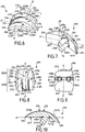
- said prosthesis 100 comprises a talar component 200, a preferred embodiment of which is illustrated in FIGS. Figures 6 to 10 and which is advantageously intended to be attached to the talus of a foot of the patient.
- the talar component 200 comprises an upper talar surface 201, which defines a first articular surface 202 of the prosthesis 100.
- said upper talar surface 201 extends between an anterior forewing edge 203 and a posterior posterior edge 204 according to a first mean direction AA 'mean and, preferably, between a talar side edge 205 and a medial talar edge 206 opposite a second mean direction BB', orthogonal to said first direction AA 'average.
- said first average direction AA ' may correspond to a first average anteroposterior direction in normal use of the prosthesis 100.
- Said second direction BB' mean may then advantageously correspond to a first median latero-medial direction.
- said talar lateral edge 205 and said medial talar edge 206 are rounded, chamfered.
- posterior anterior
- anterior anterior
- immediate anterior
- lateral lateral
- the talar component 200 also comprises a lower talar surface 207, opposite to said upper talar surface 201, and which is advantageously connected to the latter at said anterior forewing edge 203 and posterior posterior edge 204
- Said lower talar surface 207 is preferably intended to be positioned in contact in or on an area of the talus (or talus) of the patient specially prepared beforehand.
- the talar lower face 207 is defined by first and second substantially planar contiguous portions ( figure 7 ), which extend generally in respective secant planes, for example at an elevation angle of 30 ° of the first planar portion relative to the second planar portion.
- the first planar portion preferably forms an anterior portion of the lower talar face 207, while the second flat portion, which extends in a substantially horizontal plane in normal use of the prosthesis 100 according to the invention, advantageously forms a portion at the Once central and posterior talar underside 207.
- a leave may be provided at the junction of said first and second planar portions.
- the talar component 200 may also comprise a medial talar face 208 and an opposing talar lateral face 209, which respectively connect the medial talar edge 206 and the talar lateral edge 205 to said talar lower face 207.
- said talar medial face 208 and lateral talar surface 209 are generally convex towards the outside of the talar component 200, in order to better respect the natural anatomical conformation of the talus area at which the talar component 200 is intended to be put in place .
- the prosthesis 100 comprises a tibial component 300 ( Figures 11 to 15 ), intended to be attached to a lower end of the patient's tibia.
- Said tibial component 300 has a tibial upper face 301 and a tibial lower face 302 opposite.
- said tibial lower face 302 preferably extends, on the one hand, between an anterior tibial edge 303 and an opposite posterior tibial edge 304, preferably in a third mean direction CC 'and, on the other hand, between a tibial lateral edge 305 and an opposing tibial medial edge 306, preferably in a fourth mean direction DD 'orthogonal to said third mean direction CC'.
- said third average direction CC ' may correspond to a second average anteroposterior direction in normal use of the prosthesis 100.
- Said fourth direction DD' mean may then advantageously correspond to a second mean latero-medial direction.
- Said second mean antero-posterior direction and second medial latero-medial direction of the tibial component 300 are advantageously respectively parallel to said first mean anteroposterior direction and first medial lateromial direction of the talar component 200, in normal use of the prosthesis 100.
- the tibial upper face 301 and the tibial lower face 302 respectively extend in substantially parallel mean extension planes, said tibial component 300 being in the general form of a plate.
- Said upper tibial surface 301 is preferably intended to be positioned in contact in or on a zone of the tibia specially primed beforehand.
- the tibial component 300 can also comprise a tibial medial face 307 and an opposite tibial lateral face 308, which respectively connect the tibial medial edge 306 and the tibial lateral edge 305 to said tibial upper face 301.
- said tibial medial edge 306 is substantially rectilinear and said medial face tibial 307 is substantially flat ( Figures 11 to 14 ), so that the surgeon can accurately position said tibial component 300 in the patient's body, aligning said tibial medial face 307 along a rectilinear section made at the level of the medial malleolus.
- the tibial component 300 may comprise an anterior tibial surface 309 and an opposite posterior tibial surface 310, which in turn respectively connect the tibial anterior edge 303 and the posterior tibial edge 304 to said tibial upper face 301.
- said talar component 200 and / or said tibial component 300 respectively form a one-piece piece of a biocompatible and wear-resistant material.
- said talar component 200 and / or said tibial component 300 are made of a metallic material, for example chromium-cobalt CrCo alloy, stainless steel or titanium.
- said talar component 200 and said tibial component 300 are respectively a casting part.
- said talar component 200 and said tibial component 300 are respectively a machined part.
- suitable materials may be envisaged, such as for example a ceramic material, as well as other methods of manufacture (by injection, molding, sintering, etc.).
- the lower talar surface 207 of the talar component 200 and / or the upper tibial surface 301 of the tibial component 300 may be provided with a particular surface coating (for example porous titanium or hydroxyapatite), or have subject of a particular mechanical treatment (sandblasting, grooving, etc.), to promote bone attachment of talar component 200 to the talus and / or tibial component 300 to the corresponding tibia.
- a particular surface coating for example porous titanium or hydroxyapatite
- a particular mechanical treatment sandblasting, grooving, etc.
- the prosthesis 100 according to the invention also comprises an intermediate component 400 (or shoe, or insert) ( Figures 16 to 19 ), which is adapted to be interposed between said talar component 200 and said tibial component 300, as illustrated as an example to Figures 1 to 5 .
- Said intermediate component 400 comprises an intermediate upper face 401, preferably intended to come into contact with the tibial lower face 302 of the tibial component 300, and an opposite lower face 402 opposite, which is in turn preferably intended to come into contact with the face upper talar component 200 of the talar component 200.
- Said intermediate lower face 402 advantageously defines a second articular surface 403 of the prosthesis 100, designed to cooperate with said first articular surface 202 defined by the upper talar surface 201 of the talar component 200.
- said intermediate upper face 401 extends firstly between a first intermediate front edge 404 and a first intermediate rear edge 405 opposite (for example in a fifth direction EE 'mean) and, secondly, between a first intermediate lateral edge 406 and a first intermediate medial edge 407 opposite (for example in a sixth direction FF mean, orthogonal to said fifth direction EE 'mean).
- Said intermediate lower face 402 preferably extends, on the one hand, between a second intermediate front edge 408 and a second rear intermediate edge 409 opposite, in the said fifth direction EE 'mean and, on the other hand, between a second edge intermediate lateral 410 and a second intermediate medial edge 411 opposite, in said sixth direction FF 'mean.
- the intermediate component 400 may also comprise an intermediate medial face 412 and an intermediate lateral face 413 opposite, which respectively connect the first intermediate medial edge 407 and the first intermediate lateral edge 406 to said intermediate lower face 402.
- the intermediate medial face 412 is substantially flat, for reasons substantially identical to those described above in connection with the tibial medial face 307 of the tibial component 300, while the intermediate lateral face 413 may be generally curved, with a concavity oriented towards said intermediate medial face 412.
- the comp Intermediate element 400 may comprise an intermediate front face 414 and an opposite rear intermediate face 415, which in turn respectively connect the first front edge. intermediate 404 and the first intermediate posterior edge 405 to said intermediate lower face 402.
- the intermediate component 400 is capable of slidingly moving in contact with the talar component 200 in an average anteroposterior direction and, in particular, in a generally postero-anterior (i.e., posterior) stroke. forward) between the posterior posterior edge 204 (plantar flexion, figure 3 ) and the anterior forewing margin 203 (dorsal flexion, figure 5 ), via a so-called neutral interim position ( figure 4 ), according to the inclination affected by the foot of the patient relative to his tibia.
- a generally postero-anterior i.e., posterior
- said intermediate component 400 is a one-piece piece made of a material having a low coefficient of friction, for example a plastic material such as a high-density polyethylene (HDPE). It may be, for example, a machined or molded part.
- a plastic material such as a high-density polyethylene (HDPE).
- HDPE high-density polyethylene
- the prosthesis 100 could not comprise an intermediate component 400, the lower tibial surface 302 can then be designed to define by itself a second articular surface intended to cooperate directly with the first articular surface 202 defined by the upper talar surface 201 of the talar component 200.
- said first articular surface 202 is curved, convex, in said first direction AA 'means.
- the second articular surface 403 defined by the intermediate lower face 402 of the talar component 400 is preferably curved along said fifth direction EE 'mean.
- Said first articular surface 202 is preferably generally convex (that is to say with a concavity oriented towards the lower talar surface 207 of the talar component 200), while the second articular surface 403 is generally concave.
- an inverted configuration could be envisaged without departing from the scope of the invention, the first articular surface 202 being generally concave, while the second articular surface 403 is generally convex.
- said first articular surface 202 (and, preferably, said second articular surface 403) more specifically presents (each) the average general shape of a substantially frustoconical (fictitious) surface fraction derived from a fictitious cone which surface is preferably oriented so that its large base is oriented towards the external malleolus and that its small base is oriented towards the internal malleolus of the foot considered.
- the intermediate component 400 moves in frictional contact relative to the talar component 200, by cooperation of said first 202 and second 403 articular surfaces, the intermediate component 400 does not describe a strictly anteroposterior or postero-anterior trajectory, but at contrary a more or less curved trajectory.
- first 202 and second 403 articular surfaces could each have the average general shape of a cylindrical (fictional) surface fraction, so as to define an articular kinematic in which the intermediate component 400 moves in a substantially anterotic trajectory posterior or postero-anterior.
- said first articular surface 202 comprises at least two distinct curved surface portions, namely at least a first curved portion 202A and a second curved portion 202B, which each extend in said first direction AA 'mean, aligned with each other. one behind the other in said first mean direction AA ', said first curved portion 202A having a first curvature and said second curved portion 202B having a second curvature, in said first direction AA' mean.
- said first articular surface 202 is described by at least two distinct curvilinear portions (respectively designated on the figure 10 with the same references 202A and 202B as for the first and second corresponding curved portions), each preferably forming an arc whose concavity is preferably directed towards the lower talar face 207, said curvilinear portions having centers of curvature (possibly ) distinct from each other.
- said first 202A and second 202B curved portions of the first articular surface 202 are respectively broadly comparable to a first and a second fraction of (fictitious) substantially frustoconical surfaces, said first and second surface fractions being preferably respectively derived from a first and a second imaginary cones, virtual, respectively having a first and a second axis of rotation.
- the value of the half angle at the apex of each of said first and second fictitious cones is 8 °. The choice of this particular configuration helps to better reproduce the natural kinematics of the anatomical ankle.
- said first 202A and second 202B curved portions of the first articular surface 202 could be respectively broadly comparable to a first and a second fraction of substantially cylindrical surfaces, said first and second surface fractions being preferably respectively derived from a first and a second dummy cylinder, respectively having a first and a second axis of rotation.
- said first articular surface 202 has, as introduced above, the average general shape of a substantially frustoconical (fictitious) surface fraction resulting from a fictitious (or cylindrical) cone, this average general shape is more precisely defined, within the meaning of the invention, by the combination of at least a first and a second distinct fractions of substantially frustoconical (or cylindrical) surfaces.
- each of these substantially frustoconical surfaces is preferably oriented so that its large base is oriented towards the external malleolus and that its small base is oriented towards the internal malleolus of the foot considered.
- the first fraction of frustoconical surface corresponding to the first curved portion 202A has a radius of curvature which varies, in a latero-medial direction of said second direction BB 'mean, decreasingly between a large radius R 1 of curvature and a small radius r 1 of curvature.
- the second fraction of frustoconical surface corresponding to the second curved portion 202B, has a radius of curvature which varies, in a latero-medial direction, of said second direction BB 'mean, decreasingly between a large radius R 2 of curvature and a small radius r 2 of curvature.
- the latter may be respectively have a radius of curvature R ' 1 , R' 2 which is constant in said second mean direction BB 'mean.
- said first and second curvatures are different, so that one of said first 202A and second 202B curved portions is therefore more curved, ie more strongly curved, than the other.
- said first 202A and second 202B curved portions of the first articular surface 202 are respectively broadly comparable to a first and a second fraction of (frustoconical) substantially frustoconical surfaces
- such difference in curvature can result in the fact that the first fraction of frustoconical surface has a large radius R 1 of curvature and a small radius r 1 of curvature which are respectively different from the large radius R 2 of curvature and small radius r 2 of curvature respective portions of the second frustoconical surface fraction (R 1 ⁇ R 2 and r 1 ⁇ r 2 ).
- first 202A and second 202B curved parts are respectively broadly comparable to a first and a second fraction of substantially cylindrical surfaces
- a difference in curvature may result in the first cylindrical surface fraction having a radius R ' 1 of curvature different from the respective radius of curvature R' 2 of the second cylindrical surface fraction.
- the first articular surface 202 defined by the upper talar face 201 advantageously does not have the exact and perfect shape of a frustoconical (or cylindrical) surface portion, as envisaged above in alternative), but that it comprises on the contrary a particular localized variation in its average general curvature in said first direction AA 'average.
- the general kinematics of the prosthesis 100 is then not defined by a single rotation, but by at least two rotations with different radii, corresponding to at least two spatial configurations of the foot relative to the tibia. It is thus possible to generate a complex articular movement, with differentiated axes of rotation of the prosthetic joint between a plantar flexion position and a dorsal flexion position, and to approach even more faithfully the natural kinematic behavior of an anatomical ankle.
- said first curved portion 202A and said second curved portion 202B define (or contribute to defining at least in part) respectively an anterior portion and a posterior portion of said first articular surface 202.
- said first curved portion 202A preferably extends between the anterior talar edge 203 and the posterior talar edge 204 of the upper talar face 201 of the talar component 200, and preferably from said former talar edge 203 (or at least from the immediate vicinity of the latter) towards said posterior posterior edge 204.
- Said second curved portion 202B then extends respectively between said first curved portion 202A and said trailing posterior edge 204.
- said second curved portion 202B is contiguous with said first curved portion 202A and extends the latter to said posterior posterior edge 204 (or at least up to the immediate vicinity thereof) ).
- the first curved portion 202A and the second curved portion 202B are therefore aligned one behind the other in the first direction AA 'mean, the first curved portion 202A (anterior portion) being arranged in front of the second curved portion 202B (posterior portion) .
- said first articular surface 202 is described by at least two distinct and preferably abutting curvilinear portions, each preferably forming an arc, and preferably connecting the anterior forewing edge 203 to the posterior dorsal edge 204.
- Said first curved portion 202A then corresponds advantageously to a part of the first articular surface 202 with which the second articular surface 403 of the intermediate component 400 will cooperate, in a configuration of dorsal flexion of the patient's foot ( figure 5 ), while said second curved portion 202 corresponds to another part of the first articular surface 202 with which said second articulating surface 403 of the intermediate component 400 will cooperate, in plantar flexion configuration of the patient's foot ( figure 3 ).
- said first and second curvatures, as well as the relative positioning of said first and second axes of rotation, will be chosen so as to ensure a smooth and smooth transition between said first 202A and second 202B curved parts of the first articular surface 202.
- said first and second fractions of substantially frustoconical surfaces meet in a contact plane inclined at an angle of between 10 °. and 30 °, and preferably about 20 °, in the direction of said forward anterior edge 203 with respect to a vertical plane containing said second axis of rotation, said contact plane containing said first and second axes of rotation.
- said first curvature of the first curved portion 202A is greater than said second curvature of the second curved portion 202B, i.e. said first curved portion 202A of the first articular surface 202 affects, in the first direction AA 'mean, a curvature greater than that respective said second curved portion 202B of the first articular surface 202 (R 1 ⁇ R 2 and r 1 ⁇ r 2 , or R' 1 ⁇ R ' 2 ).
- said first articular surface 202 then advantageously has a more pronounced curvature in its portion. earlier than in its posterior portion.
- Such a configuration is particularly interesting, since it allows the patient to allow dorsal flexion with greater angular deflection, without the fact that the patient's talus is deported in an antero-posterior direction. that is to say towards the back. Equipped with the prosthesis 100 according to the invention, the patient can thus more easily bend his foot, for example during the phase of walking where the foot leaves the ground at the end of a step, or when he seeks to climb the steps of a staircase.
- said first curvature is constant or variable (in the first direction AA 'mean), while said second curvature is constant (in the first direction AA' mean).
- a first variable curvature may advantageously correspond to a particular embodiment in which the general shape of the first curved portion 202A is itself globally defined by the combination of a plurality n of distinct fractions of substantially frustoconical or cylindrical surfaces (and not by the only first fraction mentioned above), which fractions would have small r n and large R n rays (or radii R ' n ) of different curvature (and therefore nth different curvatures), advantageously decreasing in said first direction AA 'average.
- the implementation of such a first variable curvature advantageously allows d to further improve the amplitude of the angular deflection offered by the prosthesis 100 in dorsal flexion.
- said second curved portion 202B is preferably designed and sized so that it advantageously has an area greater than the respective area of said first curved portion 202A. This ensures better recovery of intra-articular efforts in plantar flexion, which improves both the stability and the life of the prosthesis 100.
- said talar lateral zone 210L and talar medial zone extend respectively from said talar anterior edge 203 (or at least from the immediate vicinity of the latter) to said posterior posterior edge 204 (or at least to the immediate vicinity of this last).
- Said lateral talar zone 210L then comprises a first lateral region 211L of said first curved portion 202A and a second lateral region 212L of said second curved portion 202B.
- Said medial talar area 210M comprises respectively a first medial region 211M of said first curved portion 202A and a second medial region 212M of said second curved portion 202B.
- the second lateral region 212L and second medial region 212M then preferably extend respectively said first lateral region 211L and first medial region 211L, in the first direction AA 'means.
- said talar lateral zone 210L and medial talar zone 210M thus form respectively continuous lateral and medial prosthetic condyle portions in the first direction AA 'mean.
- said first articular surface 202 also comprises a central talar zone 210C, which is interposed between said talar lateral zone 210L and said medial talar zone 210M.
- said central talar zone 210C extends, along said first direction AA 'average, from said anterior forewing edge 203 (or at least from the immediate vicinity of the latter) towards the posterior dorsal edge 204, and advantageously comprises a first central region 211C of said first curved portion 202A.
- said central talar zone 210C also comprises a second curved central region 213C which extends said first central region 211C towards the posterior posterior edge 204.
- said second central region 213C preferably does not constitute, as a that such, a central region of the second curve portion 202B.
- said second central region 213C advantageously has a third curvature, in the first direction AA 'mean, which is different from said second curvature of the second curved portion 202B.
- Said second curve portion 202B is then discontinuous in the second direction BB 'mean.
- said third curvature of the second central region 213C is advantageously greater than said second curvature.
- the second central region 213C is thus more strongly curved than the second lateral region 212L and second medial region 212M surrounding.
- said third curvature may be identical to said first curvature, the second central region 213C being in continuity with the first central region 211C.
- said second central region 213C then advantageously materializes a posterior central depression 214 in the middle envelope of said first articular surface 202.
- said central talar zone 210C of the first articular surface 202 may not extend to the edge posterior talar 204 of the upper talar surface 201.
- the space thus formed between said central talar zone 210C and said posterior posterior edge 204 may be left free or, on the contrary, preferably be filled by a complementary portion 215 upper face talar 201 full , and for example planar, so as to avoid the formation of an uncoated bone cutting zone.
- said intermediate lateral zone 416L and medial intermediate zone 416M advantageously have, in said fifth direction EE 'mean, curvatures respectively conjugated to the curvatures of said second lateral region 212L and second medial region 212M of the second curved portion 202B of said first articular surface 202.
- Said intermediate central zone 416C advantageously has, according to said fifth direction EE 'mean, a e curvature conjugate to the curvature of said first central region 211C of the first curved portion 202A of said first articular surface 202.
- said talar central zone 210C has a convex curvature along said second mean direction BB ', said talar lateral zone 210L and medial zone talar 210M respectively having a concave curvature in said second mean direction BB 'mean.
- the intermediate lateral zone 416L and the intermediate medial zone 416M are advantageously convex along said sixth mean direction FF ', whereas the intermediate central zone 416C is concave along the same direction FF' ( figure 17 ).
- said intermediate lateral zone 416L and intermediate medial zone 416M may advantageously be respectively in surface contact against said second lateral region 212L and second medial region 212M of the second curved portion 202B of the first articular surface 202.
- said intermediate central zone 416C may advantageously rest in surface contact with the first central region 211C of the first curved portion 202A of the first articular surface 202.
- said intermediate lateral zone 416L and intermediate medial zone 416M can not then, preferably, resting in surface contact against said first lateral region 211L and first medial region 211M of the first curved portion 202A of the first articular surface 202, due to their respective different curvatures.
- the cooperation of said first and second articular surfaces is advantageously not perfectly congruent.
- the intermediate component 400 advantageously remains free to slide and tilt slightly, laterally or medially, around an equilibrium position.
- the intermediate lateral zone 416L of the second articular surface 403 can advantageously come into linear contact with the first lateral region 211L of the first curved portion 202A of the first articular surface 202 defined by the upper talar face. 201 of the talar component 200.
- the intermediate medial zone 416M of said second articular surface 403 can advantageously come into linear contact with the first medial region 211M of the first curved portion 202A of the first surface.
- the intermediate component 400 advantageously has a certain limited latitude for rotation about a vertical axis.
- such a configuration advantageously makes it possible, to a certain extent, to compensate for a slight relative positioning defect of the talar 200 and tibial 300 components, which contributes to facilitating the placement of the prosthesis 100 by the surgeon in the patient's body. .
- the intermediate central zone 416C preferably has, in accordance with the foregoing, a curvature greater than that of the intermediate lateral zone 416L and intermediate medial zone 416M, it can then define, close to the second intermediate posterior edge 409, a protrusion 417 protruding from the surface of the intermediate lower face 402 ( figure 17 ).
- said posterior central depression 214 represented by the second central region 213C of the central talar zone 210C, as mentioned above
- said protrusion 417 can advantageously be erased in said posterior central depression 214.
- said tibial component 300 is designed to be movable relative to said intermediate component 400, said tibial 300 and intermediate 400 components then not being preferably mechanically interconnected.
- said tibial lower face 302 and said intermediate upper face 401 are preferably substantially planar and smooth, so that the tibial component 300 and the intermediate component 400 can come into planar surface contact against each other .
- the tibial component 300 and the intermediate component 400 are thus in contact with one another, and are movable relative to each other in three degrees of freedom, namely according to a mean antero-posterior directional translation, a mediolateral mean directional translation, and a rotation about an axis orthogonal to the contact plane of said tibial lower face 302 and intermediate upper face 401 therebetween.
- said tibial component 300 is designed to be fixed, that is to say secured, to said intermediate component 400, so as to advantageously suppress any degree of freedom between the tibial component 300 and the intermediate component 400.
- Such a fastening of the latter advantageously improves the stability of the prosthetic joint.
- said tibial component 300 and intermediate component 400 are adapted to be affixed to each other by means of first and second respective complementary securing elements, more preferably in a dovetail assembly.
- the tibial lower face 302 of the tibial component 300 is thus advantageously provided with a groove 311, for example of trapezoidal section, which advantageously forms said first securing element (or female member in the tail end). dove).
- the intermediate upper face 401 of the intermediate component 400 is reciprocally advantageously provided with a pin 418, which forms said second securing element (or male dovetail member).
- said post 418 projects from the surface of said intermediate upper face 401 and is of shape and dimensions complementary to that of said groove 311.
- said groove 311 extends longitudinally along said third middle direction CC 'from the face tibial component 309 of the tibial component 300, at which it opens out, towards the posterior tibial surface 310, and over at least half of the mean distance between said anterior tibial surface 309 and posterior tibial surface 310 ( Figures 12 and 14 ).
- said post 418 extends longitudinally along said fifth direction EE 'mean, from the intermediate front face 414 of the intermediate component 400, towards the intermediate rear face 415 thereof.
- the length of said stud 418 is smaller than the respective length of said groove 311 ( Figures 16 and 18 ).
- Said groove 311 is thus advantageously designed and configured to receive a narrow sliding said pin 418, said lower tibial face 302 and intermediate upper face 401 then being held pressed against each other.
- Such a relative dovetail assembly thus advantageously makes it possible to block at least any mediolateral translation and any rotation of the intermediate component 400 relative to the tibial component 300.
- said post 418 can be provided, at its posterior end of lateral slopes 419A, 419B (or chamfers) designed to facilitate, guide, the introduction of the pin 418 in the groove 311 during the relative assembly of the tibial component 300 and the intermediate component 400.
- said tibial component 300 and intermediate component 400 preferably furthermore comprise respectively complementary first and second abutment elements designed to limit or block the anteroposterior translation (c '). that is to say, from the front to the back) of the intermediate component 400 relative to the tibial component 300, said first and second stop elements being advantageously distinct from said first and second complementary securing elements.
- the limitation (and preferably the blocking) of the anteroposterior translation is advantageously not ensured (or, at least not exclusively) by the assembly of a tail. aronde itself, but by the cooperation of said first and second complementary abutment elements.
- said first and second abutment members respectively comprise a flange 312 positioned at least at level of the posterior tibial edge 304 of the tibial lower face 302 of the tibial component 300, and a clearance 420 formed at the intermediate upper face 401 of the intermediate component 400 (for example at the first intermediate posterior edge 405) and complementary profile to said flange 312.
- Said clearance 420 is thus designed and configured to receive said flange 312, said tibial lower face 302 and intermediate upper face 401 being advantageously in plane contact with one another.
- the cooperation of said flange 312 and clearance 420 thus limits, and preferably block, the anteroposterior stroke of the pin 418 in the groove 311. Obviously stop elements of different design could be implemented.
- said flange 312 is positioned at said posterior tibial edge 304, tibial lateral edge 305 and tibial medial edge 306 of the tibial lower face 302 of the tibial component 300, and advantageously extends substantially continuous along the edges 304, 305, 306 in question.
- Said flange 312 preferably has a rectangular section, constant or not.
- said clearance 420 is preferably arranged at the level of the first intermediate posterior edge 405, first intermediate lateral edge 406 and first intermediate medial edge 407 of the intermediate upper face 401 of said intermediate component 400, advantageously substantially continuously along the edges 405, 406, 407 in question.
- said tibial component 300 and intermediate component 400 are advantageously respectively provided with first 313A, 313B and second 421A, 421B complementary locking means.
- said first locking means 313A, 313B may, for example, take the form of notches 313A, 313B tooth saw provided in the rim 312 of the lower tibial face 302, for example symmetrically at the tibial lateral edge 305 and the tibial medial edge 306 of said tibial component 300.
- said second locking means 421A, 421B may to it, take the form, for example, pins 421A, 421B complementary shapes to said notches 313A, 313B sawtooth, arranged at the clearance 420 of the intermediate component 400 ( Figures 16 to 18 ).
- the tibial component 300 and the intermediate component 400 can thus be locked to one another by clipping, the local elastic deformation of the material forming the intermediate component 400 allowing the engagement of the lugs 421A, 421B of the latter in the notches 313A , 313B corresponding tibial component 300.
- first 313A, 313B and second 421A, 421B suitable complementary locking means may be considered in place of those just described.
- the tibial component 300 is designed to be fixed removably to the intermediate component 400, in particular to allow the replacement of the intermediate component 400 in case of degradation of the latter (wear, deformation, etc.).
- the first 313A, 313B and second 421A, 421B complementary locking means will be designed to allow reversible locking of the tibial component 300 and the intermediate component 400 therebetween.
- the intermediate component 400 may, for example, be provided with recesses 422A, 422B formed in the intermediate upper face 401 in the immediate vicinity of the lugs 421A, 421B forming said second locking means 421A, 421B, and designed to receive the end of an external instrument (not shown, for example a flat screwdriver).
- this external instrument advantageously allows local elastic deformation of the material forming the intermediate component 400 and a decoupling of the notches 313A, 313B and lugs 421A, 421B, thus allowing the uncoupling talar 300 and intermediate 400 components.
- the talar component 200 is provided at its lower talar surface 207 with at least one talar anchoring means 216A, designed to anchor the talar component 200 in the bone mass of the slope concerned.
- said talary anchoring means 216A is advantageously intended to be housed, during the establishment of the talar component 200 in the body of the patient, in a housing (or hole) corresponding previously practiced (or during the establishment of the talar component 200) by the surgeon in the bone mass of the talus.
- the talar component 200 is provided with two talar anchoring means 216A, 216B, formed by two talar pads 216A, 216B, for example cylindrical with a rounded head, which project from the lower talar surface 207 of the talar component 200.
- said talar pads 216A, 216B extend inclined towards the posterior dorsal edge 204.
- talar anchoring means 216 may be envisaged.
- each talar anchoring means 216A, 216B is thus advantageously connected to the lower talar face 207 by a respective talar leave 217A, 217B.
- Such a fillet 217A, 217B may be particularly unfavorable in the case, envisaged above, where the lower talar surface 207 is provided with a surface coating, since the presence of the latter tends, according to its thickness, to amplify the importance of said leave 217A, 217B, and thus to further impede the establishment of said talar component 200.
- said talar lower face 207 is advantageously provided with at least one talar bowl 218A, from the bottom of which said at least one talar anchoring means 216A projects from said lower talar surface 207.
- said lower talar face 207 is advantageously provided with a plurality of talar bowls 218A, 218B from respective bottom of which said tali blocks 216A, 216B protrude from said tibial upper face 301.
- said talar bowl 218A, 218B is advantageously dimensioned so that said fillet 217A, 217B is integrally contained in said talar bowl 218A 218B and therefore does not protrude from the surface of the lower talar surface 207.
- said talar component 200 can be placed in a relatively simple and precise way at the slope, the lower talar surface 207 being able to come into surface contact. perfect with the corresponding slope area, without the need for specific tools for drilling bone mass.
- the tibial component 300 is provided at its tibial upper face 301 with at least one tibial anchoring means 314A designed to anchor the tibial component 300 in the bone mass of the tibia concerned.
- said tibial anchoring means 314A is advantageously intended to be housed, during the introduction of the tibial component 300 into the body of the patient, into at least one housing (or hole) made beforehand (or during the introduction of the tibial component 300) by the surgeon in the bone mass of the tibia.
- the tibial component 300 is preferably provided with a plurality of tibial anchoring means 314A, 314B, 314C, 314D, for example formed of two tibial studs 314A, 314B with rounded head protruding from said upper tibial face 301 in the vicinity of the anterior tibial edge 303, and two tibial fins 314C, 314D, which project from said tibial upper face 301 in the vicinity of the posterior tibial edge 304.
- said tibial fins 314C, 314D have sharp or even sharp edges , to promote their penetration into the bone mass of the tibia.
- said tibial pads 314A, 314B and said tibial fins 314C, 314D extend inclined towards the posterior tibial edge 304.
- the angle of inclination of said tibial pads 314A, 314B and said tibial fins 314C, 314D will advantageously be chosen to facilitate the introduction of the tibial component 400 into the body of the patient, and its establishment in the tibia of the latter, limiting the necessary joint distraction.
- tibial anchor means (s) 314A, 314B, 314C, 314D may be contemplated.
- said at least one tibial anchoring means 314A is preferably connected to the upper face tibial 301, at its base, by a tibial leave 315A.
- Said upper tibial surface 301 is then advantageously provided with at least one tibial cup 316A, from the bottom of which said at least one tibial fixation means 314A projects from said tibial upper surface 301.
- each of the tibial pads 314A, 314B and each of the tibial fins 314C, 314D is thus advantageously connected to the tibial upper face 301 by a respective tibial leave 315A, 315B, 315A, 315B.
- Said upper tibial surface 301 is then advantageously provided with a plurality of tibial cups 316A, 316B, 316A, 316B from the respective bottom of which said tibial pads 314A, 314B and said tibial fins 314C, 314D project from said upper tibial surface 301 .
- the talar lateral edge 205 and the medial talar edge 206 of the talar component 200 are preferably respectively provided with a lateral talar notch 219L and a talar medial notch 219M, advantageously positioned symmetrically in the vicinity of the anterior forewing edge 203.
- Said lateral talar notch 219L and said talar medial notch 219M are advantageously designed to cooperate with an external instrument (not shown, for example a flat screwdriver), to allow ablation of the talar component 200, for example in case of unsatisfactory positioning or in the event of a medical complication justifying the removal of all or part of the prosthesis 100.
- the tibial lateral edge 305 and the tibial medial edge 306 of the tibial component 300 may advantageously be respectively provided with a tibial lateral notch 317L and a medial tibial notch 317M, advantageously positioned symmetrically to the neighborhood of the anterior tibial border 303 ( Figures 11, 12 and 14 ).
Landscapes
- Health & Medical Sciences (AREA)
- Orthopedic Medicine & Surgery (AREA)
- Cardiology (AREA)
- Oral & Maxillofacial Surgery (AREA)
- Transplantation (AREA)
- Engineering & Computer Science (AREA)
- Biomedical Technology (AREA)
- Heart & Thoracic Surgery (AREA)
- Vascular Medicine (AREA)
- Life Sciences & Earth Sciences (AREA)
- Animal Behavior & Ethology (AREA)
- General Health & Medical Sciences (AREA)
- Public Health (AREA)
- Veterinary Medicine (AREA)
- Prostheses (AREA)
Abstract
Description
- L'invention se rapporte au domaine général des prothèses de cheville, c'est-à-dire des dispositifs implantables destinés au remplacement d'articulations de chevilles, en particulier dans le cadre d'un traitement orthopédique.
- L'invention concerne plus précisément une prothèse de cheville, comprenant un composant talaire qui comporte une face supérieure talaire définissant une première surface articulaire et qui s'étend entre un bord antérieur talaire et un bord postérieur talaire opposé selon une première direction moyenne, ladite première surface articulaire étant incurvée selon ladite première direction moyenne.
- Afin de traiter certaines pathologies osseuses de la cheville, telle que l'arthrose, entraînant une dégradation ou une disparition du cartilage articulaire, il est connu de procéder à une arthrodèse de l'articulation tibio-tarsienne. Une telle opération d'arthrodèse vise à limiter, voire bloquer totalement, la mobilité de cheville par ostéosynthèse, afin de faire cesser la douleur articulaire ressentie par le patient. Si l'arthrodèse de l'articulation tibio-tarsienne donne généralement satisfaction, son principal inconvénient réside précisément dans la suppression de la mobilité de l'articulation, qui doit alors être compensée autant que de possible par les autres articulations de la jambe du patient. Une longue période d'adaptation est alors nécessaire au patient pour retrouver, après opération, des capacités de locomotion satisfaisantes. En outre, le blocage de l'articulation tibio-tarsienne engendre des contraintes mécaniques élevées sur les articulations voisines, lesquelles sont alors exposées à un risque élevé de dégénérescence précoce.
- C'est la raison pour laquelle il a été proposé de procéder, dans certains cas de figures, à une arthroplastie de la cheville comme alternative à l'arthrodèse, c'est-à-dire au remplacement de l'articulation endommagée de la cheville par une articulation prothétique, artificielle. Il a ainsi été introduit une prothèse de cheville formée de plusieurs composants, à savoir un composant talaire et un composant tibial, respectivement destinés à être rapportés au talus et au tibia, et un patin en plastique qui est, quant à lui, prévu pour être intercalé entre le composant talaire et le composant tibial et venir s'articuler en contact avec le composant talaire. Le recours à une telle prothèse connue permet, contrairement à l'arthrodèse classique, de conserver une bonne mobilité de la cheville du patient, facilitant ainsi la marche, et de préserver les différentes articulations du pied et de la jambe du patient. Il a cependant été observé qu'une telle prothèse de cheville connue reste encore perfectible, en particulier en matière de reproductibilité des mouvements naturels complexes de la cheville et de leur amplitude.
- Les objets assignés à la présente invention visent en conséquence à remédier aux différents inconvénients énumérés précédemment et à proposer une nouvelle prothèse de cheville présentant une cinématique améliorée, plus respectueuse des mouvements naturels de la cheville, et favorisant un retour pour le patient à une locomotion aisée et confortable.
- Un autre objet de l'invention vise à proposer une nouvelle prothèse de cheville dont la mise en place est à la fois rapide, facile et particulièrement peu traumatisante pour le patient.
- Un autre objet de l'invention vise à proposer une nouvelle prothèse de cheville, robuste et résistante, et dont la tenue dans le corps du patient est particulièrement fiable.
- Un autre objet de l'invention vise à proposer une nouvelle prothèse de cheville dont la fabrication est relativement aisée.
- Un autre objet de l'invention vise à proposer une nouvelle prothèse de cheville permettant de réduire le coût de l'intervention chirurgicale de pose de la prothèse.
- Un autre objet de l'invention vise à proposer une nouvelle prothèse de cheville permettant de réduire le risque pour la santé du patient lié à la pose de la prothèse et à la thérapie.
- Un autre objet de l'invention vise à proposer une nouvelle prothèse de cheville permettant de traiter une pathologie osseuse du patient de façon particulièrement efficace et rapide.
- Les objets assignés à l'invention sont atteints à l'aide d'une prothèse de cheville, comprenant un composant talaire qui comporte une face supérieure talaire définissant une première surface articulaire et qui s'étend entre un bord antérieur talaire et un bord postérieur talaire opposé selon une première direction moyenne, ladite première surface articulaire étant incurvée selon ladite première direction moyenne, ladite première surface articulaire comprenant une première partie courbe et une deuxième partie courbe, qui s'étendent chacune selon ladite première direction moyenne, ladite première partie courbe présentant une première courbure et ladite deuxième partie courbe présentant une deuxième courbure, ladite prothèse étant caractérisée en ce que lesdites première et deuxième parties courbes définissent respectivement une portion antérieure et une portion postérieure de ladite première surface articulaire, ladite première courbure étant supérieure à ladite deuxième courbure.
- D'autres particularités et avantages de l'invention apparaîtront et ressortiront plus en détails à la lecture de la description faite ci-après, en référence aux dessins annexés, donnés uniquement à titre d'exemple illustratif et non limitatif, dans lesquels :
- les
figures 1 et 2 illustrent, selon des vues en perspective différentes, un mode de réalisation préférentiel de la prothèse selon l'invention dans lequel cette dernière comprend, outre un composant talaire, un composant tibial et un composant intermédiaire ; - les
figures 3 à 5 , illustrent, selon des vues médiales, trois configurations spatiales que la prothèse desfigures 1 et 2 est susceptible d'adopter selon l'orientation relative des pied et tibia gauches d'un patient, à savoir respectivement à une position de flexion plantaire (figure 3 ), une position dite neutre (figure 4 ) et une position de flexion dorsale (figure 5 ) ; - les
figures 6 et 7 illustrent, respectivement selon des vues en perspective de dessus et de dessous, le composant talaire de la prothèse desfigures 1 et 2 . Lesfigures 8 et 9 illustrent, respectivement en vue de dessus et en vue de dessous, le composant talaire desfigures 6 et 7 . Lafigure 10 illustre, selon une vue en coupe antéro-postérieure, le composant talaire desfigures 6 à 9 ; - les
figures 11 et 12 illustrent, respectivement selon des vues en perspective de dessus et de dessous, le composant tibial de la prothèse desfigures 1 et 2 . Lesfigures 13 et 14 illustrent, respectivement en vue de dessus et en vue de dessous, le composant tibial desfigures 11 et 12 . Lafigure 15 illustre, selon une vue en coupe antéro-postérieure, le composant tibial desfigures 11 à 14 ; - les
figures 16 et 17 illustrent, respectivement selon des vues en perspective de dessus et de dessous, le composant intermédiaire de la prothèse desfigures 1 et 2 . Lesfigures 18 et 19 illustrent, respectivement, en vue de dessus et de dessous, le composant intermédiaire desfigures 16 et 17 . - L'invention concerne une prothèse de cheville 100, dont un mode de réalisation préférentiel est illustré aux
figures 1 et 2 . Ladite prothèse 100 constitue un dispositif implantable par voie chirurgicale dans le corps d'un patient, humain ou animal, qui est destiné au remplacement d'une articulation tibio-tarsienne donnée. Avantageusement, ladite prothèse 100 est conçue pour remplacer totalement l'articulation tibio-tarsienne concernée (prothèse totale de cheville, PTC). A ce titre, la prothèse 100 selon l'invention est conçue pour être insérée et intercalée entre une extrémité inférieure d'un tibia et un talus correspondant d'un pied du patient. Avantageusement, le tibia et le talus considérés auront fait l'objet, préalablement à la mise en place de la prothèse 100 selon l'invention dans le corps du patient, d'une préparation adéquate, et par exemple d'une extraction d'éléments cartilagineux et de coupes osseuses, de sorte à supprimer tout ou partie des surfaces articulaires naturelles de l'articulation tibio-tarsienne à remplacer. La prothèse 100 illustrée en exemple auxfigures 1 à 5 est destinée à être mise en place au niveau d'un pied gauche d'un patient. Bien évidemment, l'invention recouvre également une prothèse qui serait destinée à être mise en place au niveau d'un pied droit du patient. Avantageusement, celle-ci serait définie par symétrie, par rapport au plan sagittal du patient, de la prothèse 100 illustrée aux figures. - Conformément à l'invention, ladite prothèse 100 comprend un composant talaire 200, dont un mode de réalisation préférentiel est illustré aux
figures 6 à 10 , et qui est avantageusement destiné à être rapporté au talus d'un pied du patient. Le composant talaire 200 comporte une face supérieure talaire 201, qui définit une première surface articulaire 202 de la prothèse 100. Tel qu'illustré, ladite face supérieure talaire 201 s'étend entre un bord antérieur talaire 203 et un bord postérieur talaire 204 opposé selon une première direction A-A' moyenne et, de préférence, entre un bord latéral talaire 205 et un bord médial talaire 206 opposé selon une deuxième direction B-B' moyenne, orthogonale à ladite première direction A-A' moyenne. Avantageusement, ladite première direction A-A' moyenne pourra correspondre à une première direction antéro-postérieure moyenne en usage normal de la prothèse 100. Ladite deuxième direction B-B' moyenne pourra alors avantageusement correspondre à une première direction latéro-médiale moyenne. Avantageusement, ledit bord latéral talaire 205 et ledit bord médial talaire 206 sont arrondis, chanfreinés. - Il est ici à noter que les termes « postérieur », « antérieur », « médiat » et « latéral » sont préférentiellement utilisés dans la présente description pour qualifier des éléments ou des caractéristiques en lien avec leur orientation respective relativement au corps du patient, en usage normal de la prothèse 100. Ainsi, le terme «médial» est préférentiellement utilisé pour désigner un élément de la prothèse 100 qui destiné à être positionné et orienté du côté le plus proche de l'axe medio-sagittal (ou axe médian) du corps du patient, autrement dit le côté orienté vers l'intérieur du pied et de la jambe du patient. Par opposition, le terme « latéral » est utilisé en relation avec le côté le plus éloigné de l'axe medio-sagittal. Suivant la même logique, les termes « postérieur » et « antérieur» renvoient de préférence respectivement à un positionnement vers l'arrière, respectivement vers l'avant, relativement au plan frontal du patient.
- Selon le mode de réalisation préférentiel illustré aux figures, le composant talaire 200 comporte également une face inférieure talaire 207, opposée à ladite face supérieure talaire 201, et qui est avantageusement reliée à cette dernière au niveau desdits bord antérieur talaire 203 et bord postérieur talaire 204. Ladite face inférieure talaire 207 est préférentiellement destinée à être positionnée en contact dans ou sur une zone du talus (ou astragale) du patient spécialement apprêtée au préalable. De préférence, la face inférieure talaire 207 est définie par des première et deuxième portions contigües sensiblement planes (
figure 7 ), qui s'étendent globalement selon des plans respectifs sécants, par exemple selon un angle d'élévation de 30° de la première portion plane relativement à la deuxième portion plane. La première portion plane forme préférentiellement une portion antérieure de la face inférieure talaire 207, tandis que la deuxième portion plane, qui s'étend selon un plan sensiblement horizontal en usage normal de la prothèse 100 selon l'invention, forme avantageusement une portion à la fois centrale et postérieure de la face inférieure talaire 207. Un congé peut être prévu à la jonction desdites première et deuxième portions planes. Une telle conception de la face inférieure talaire 207, particulièrement simple, limite le nombre et la complexité des coupes osseuses nécessaires (en l'espèce, deux) à la préparation préalable du talus et facilite la mise en place du composant talaire 200 dans le corps du patient. Tel qu'illustré, le composant talaire 200 peut également comporter une face médiale talaire 208 et une face latérale talaire 209 opposée, lesquelles relient respectivement le bord médial talaire 206 et le bord latéral talaire 205 à ladite face inférieure talaire 207. De préférence, lesdites face médiale talaire 208 et face latérale talaire 209 sont globalement bombées vers l'extérieur du composant talaire 200, afin de respecter au mieux la conformation anatomique naturelle de la zone du talus au niveau de laquelle le composant talaire 200 est destiné à être mis en place. - De préférence, la prothèse 100 selon l'invention comprend un composant tibial 300 (
figures 11 à 15 ), destiné à être rapporté à une extrémité inférieure du tibia du patient. Ledit composant tibial 300 comporte une face supérieure tibiale 301 et une face inférieure tibiale 302 opposée. Tel qu'illustré, ladite face inférieure tibiale 302 s'étend préférentiellement, d'une part, entre un bord antérieur tibial 303 et un bord postérieur tibial 304 opposé, de préférence selon une troisième direction C-C' moyenne et, d'autre part, entre un bord latéral tibial 305 et un bord médial tibial 306 opposé, de préférence selon une quatrième direction D-D' moyenne, orthogonale à ladite troisième direction C-C' moyenne. Avantageusement, ladite troisième direction C-C' moyenne pourra correspondre à une deuxième direction antéro-postérieure moyenne en usage normal de la prothèse 100. Ladite quatrième direction D-D' moyenne pourra alors avantageusement correspondre à une deuxième direction latéro-médiale moyenne. Lesdites deuxième direction antéro-postérieure moyenne et deuxième direction latéro-médiale moyenne du composant tibial 300 sont avantageusement respectivement parallèles auxdites première direction antéro-postérieure moyenne et première direction latéro-médiale moyenne du composant talaire 200, en usage normal de la prothèse 100. - Dans le mode de réalisation préférentiel illustré aux figures, la face supérieure tibiale 301 et la face inférieure tibiale 302 s'étendent respectivement selon des plans d'extension moyens sensiblement parallèles, ledit composant tibial 300 se présentant sous la forme générale d'une plaque. Ladite face supérieure tibiale 301 est préférentiellement destinée à être positionnée en contact dans ou sur une zone du tibia spécialement apprêtée au préalable. Tel qu'illustré, le composant tibial 300 peut également comporter une face médiale tibiale 307 et une face latérale tibiale 308 opposée, lesquelles relient respectivement le bord médial tibial 306 et le bord latéral tibial 305 à ladite face supérieure tibiale 301. Avantageusement, ledit bord médial tibial 306 est sensiblement rectiligne et ladite face médiale tibiale 307 est sensiblement plane (
figures 11 à 14 ), de sorte à ce que le chirurgien puisse positionner précisément ledit composant tibial 300 dans le corps du patient, en alignant ladite face médiale tibiale 307 le long d'une coupe rectiligne réalisée au niveau de la malléole interne. Cela permet de réduire avantageusement les zones de coupes osseuses non recouvertes, qui pourraient favoriser l'apparition de géodes ou de kystes. En outre, le composant tibial 300 peut comporter une face antérieure tibiale 309 et une face postérieure tibiale 310 opposée, lesquelles relient quant à elles respectivement le bord antérieur tibial 303 et le bord postérieur tibial 304 à ladite face supérieure tibiale 301. - De préférence, ledit composant talaire 200 et/ou ledit composant tibial 300 forment respectivement une pièce monobloc d'un matériau biocompatible et résistant à l'usure. Avantageusement, ledit composant talaire 200 et / ou ledit composant tibial 300 sont en un matériau métallique, par exemple en alliage chrome-cobalt CrCo, en acier inoxydable, ou encore en titane. Selon une variante, ledit composant talaire 200 et ledit composant tibial 300 sont respectivement une pièce de fonderie. Selon une variante alternative, ledit composant talaire 200 et ledit composant tibial 300 sont respectivement une pièce usinée. Bien évidemment, d'autres matériaux convenables pourront être envisagés, tel que par exemple un matériau céramique, ainsi que d'autres mode de fabrication (par injection, moulage, frittage, etc.).
- De manière avantageuse, la face inférieure talaire 207 du composant talaire 200 et / ou la face supérieure tibiale 301 du composant tibial 300 pourront être pourvues d'un revêtement de surface particulier (par exemple en titane poreux ou en hydroxyapatite), ou avoir fait l'objet d'un traitement mécanique particulier (sablage, rainurage, etc.), afin de favoriser l'accroche osseuse du composant talaire 200 au talus et/ou du composant tibial 300 au tibia correspondant.
- De préférence, la prothèse 100 selon l'invention comprend également un composant intermédiaire 400 (ou patin, ou encore insert) (
figures 16 à 19 ), qui est conçu pour être intercalé entre ledit composant talaire 200 et ledit composant tibial 300, comme illustré en exemple auxfigures 1 à 5 . Ledit composant intermédiaire 400 comprend une face supérieure intermédiaire 401, préférentiellement destinée à venir en contact avec la face inférieure tibiale 302 du composant tibial 300, et une face inférieure intermédiaire 402 opposée, qui est quant à elle préférentiellement destinée à venir en contact avec la face supérieure talaire 201 du composant talaire 200. Ladite face inférieure intermédiaire 402 définit avantageusement une deuxième surface articulaire 403 de la prothèse 100, conçue pour coopérer avec ladite première surface articulaire 202 définie par la face supérieure talaire 201 du composant talaire 200. - De préférence, ladite face supérieure intermédiaire 401 s'étend d'une part entre un premier bord antérieur intermédiaire 404 et un premier bord postérieur intermédiaire 405 opposé (par exemple selon une cinquième direction E-E' moyenne) et, d'autre part, entre un premier bord latéral intermédiaire 406 et un premier bord médial intermédiaire 407 opposé (par exemple selon une sixième direction F-F' moyenne, orthogonale à ladite cinquième direction E-E' moyenne). Ladite face inférieure intermédiaire 402 s'étend quant à elle préférentiellement d'une part entre un deuxième bord antérieur intermédiaire 408 et un deuxième bord postérieur intermédiaire 409 opposé, selon ladite cinquième direction E-E' moyenne et, d'autre part, entre un deuxième bord latéral intermédiaire 410 et un deuxième bord médial intermédiaire 411 opposé, selon ladite sixième direction F-F' moyenne. Ledit deuxième bord antérieur intermédiaire 408 et ledit deuxième bord postérieur intermédiaire 409 peuvent être avantageusement chanfreinés, tel qu'illustré, pour limiter les risques d'irritation ou d'endommagement des tissus mous environnants, en usage de la prothèse 100. Le composant intermédiaire 400 peut également comporter une face médiale intermédiaire 412 et une face latérale intermédiaire 413 opposée, lesquelles relient respectivement le premier bord médial intermédiaire 407 et le premier bord latéral intermédiaire 406 à ladite face inférieure intermédiaire 402. Avantageusement, la face médiale intermédiaire 412 est sensiblement plane, pour des raisons sensiblement identiques à celles exposées ci-avant en lien avec la face médiale tibiale 307 du composant tibial 300, tandis que la face latérale intermédiaire 413 peut être globalement bombée, avec une concavité orientée en direction de ladite face médiale intermédiaire 412. En outre, le composant intermédiaire 400 peut comporter une face antérieure intermédiaire 414 et une face postérieure intermédiaire 415 opposée, lesquelles relient quant à elles respectivement le premier bord antérieur intermédiaire 404 et le premier bord postérieur intermédiaire 405 à ladite face inférieure intermédiaire 402.
- Tel qu'illustré aux
figures 3 à 5 , le composant intermédiaire 400 est susceptible de se déplacer en glissant en contact sur le composant talaire 200 suivant une direction antéro-postérieure moyenne et, en particulier, selon une course globalement postéro-antérieure (c'est-à-dire de l'arrière vers l'avant) entre le bord postérieur talaire 204 (flexion plantaire,figure 3 ) et le bord antérieur talaire 203 (flexion dorsale,figure 5 ), en passant par une position intérimaire dite neutre (figure 4 ), selon l'inclinaison affectée par le pied du patient par rapport à son tibia. - De préférence, ledit composant intermédiaire 400 est une pièce monobloc en un matériau présentant un faible coefficient de frottement, par exemple un matériau plastique tel qu'un polyéthylène haute densité (PEHD). Il peut s'agir, par exemple, d'une pièce usinée ou moulée.
- Alternativement, la prothèse 100 pourrait ne pas comprendre de composant intermédiaire 400, la face inférieure tibiale 302 pouvant alors être conçue pour définir par elle-même une deuxième surface articulaire destinée à coopérer directement avec la première surface articulaire 202 définie par la face supérieure talaire 201 du composant talaire 200.
- Selon l'invention, et tel que cela ressort notamment de la
figure 6 , ladite première surface articulaire 202 est incurvée, bombée, selon ladite première direction A-A' moyenne. Réciproquement, la deuxième surface articulaire 403 définie par la face inférieure intermédiaire 402 du composant talaire 400 est préférentiellement incurvée selon ladite cinquième direction E-E' moyenne. Ladite première surface articulaire 202 est de préférence globalement convexe (c'est-à-dire avec une concavité orientée en direction de la face inférieure talaire 207 du composant talaire 200), tandis que la deuxième surface articulaire 403 est globalement concave. Selon une variante de réalisation alternative (non illustrée), une configuration inversée pourrait être envisagée sans pour autant sortir du cadre de l'invention, la première surface articulaire 202 étant globalement concave, tandis que la deuxième surface articulaire 403 est globalement convexe. - Avantageusement, ladite première surface articulaire 202 (et, de préférence, ladite deuxième surface articulaire 403) présente(nt) plus spécifiquement (chacune) la forme générale moyenne d'une fraction de surface (fictive) sensiblement tronconique, issue d'un cône fictif, laquelle surface est préférentiellement orientée pour que sa grande base soit orientée en direction de la malléole externe et que sa petite base soit orientée en direction de la malléole interne du pied considéré. Ainsi, lorsque le composant intermédiaire 400 se déplace en contact de frottement relativement au composant talaire 200, par coopération desdites première 202 et deuxième 403 surfaces articulaires, le composant intermédiaire 400 ne décrit pas une trajectoire strictement antéro-postérieure ou postéro-antérieure, mais au contraire une trajectoire plus ou moins courbe. Le pied du patient est ainsi avantageusement guidé sur le côté latéral (sens médio-latéral) en flexion dorsale et, inversement, sur le côté médial (sens latéro-médial) en flexion plantaire. On reproduit ainsi au mieux la cinématique physiologique naturelle de l'articulation de la cheville. Alternativement, lesdites première 202 et deuxième 403 surfaces articulaires pourraient présenter chacune la forme générale moyenne d'une fraction de surface (fictive) cylindrique, de sorte à définir au contraire une cinématique articulaire dans laquelle le composant intermédiaire 400 se déplace selon une trajectoire sensiblement antéro-postérieure ou postéro-antérieure.
- Selon l'invention, ladite première surface articulaire 202 comprend au moins deux parties surfaciques courbes distinctes, à savoir au moins une première partie courbe 202A et une deuxième partie courbe 202B, qui s'étendent chacune selon ladite première direction A-A' moyenne, alignées l'une derrière l'autre selon ladite première direction A-A' moyenne, ladite première partie courbe 202A présentant une première courbure et ladite deuxième partie courbe 202B présentant une deuxième courbure, selon ladite première direction A-A' moyenne. Ainsi, lorsqu'elle est vue en coupe dans plan parallèle à ladite première direction A-A' moyenne et orthogonal à ladite deuxième direction B-B' moyenne (
figure 10 ), ladite première surface articulaire 202 est décrite par au moins deux portions curvilignes distinctes (respectivement désignées sur lafigure 10 par les mêmes références 202A et 202B que pour les première et deuxième parties courbes correspondantes), formant chacune de préférence un arc dont la concavité est préférentiellement dirigée en direction de la face inférieure talaire 207, lesdites portions curvilignes ayant des centres de courbure (éventuellement moyens) distincts l'un de l'autre. - Selon une variante préférentielle, lesdites première 202A et deuxième 202B parties courbes de la première surface articulaire 202 sont respectivement globalement assimilables à une première et à une deuxième fractions de surfaces (fictives) sensiblement tronconiques, lesdites première et deuxième fractions de surfaces étant de préférence respectivement issues d'un premier et d'un deuxième cônes fictifs, virtuels, présentant respectivement un premier et un deuxième axes de rotation. De manière avantageuse, la valeur du demi-angle à l'apex de chacun desdits premier et deuxième cônes fictifs est de 8°. Le choix de cette configuration particulière contribue à reproduire au mieux la cinématique naturelle de la cheville anatomique. Alternativement, lesdites première 202A et deuxième 202B parties courbes de la première surface articulaire 202 pourraient être respectivement globalement assimilables à une première et à une deuxième fractions de surfaces sensiblement cylindriques, lesdites première et deuxième fractions de surfaces étant de préférence respectivement issues d'un premier et d'un deuxième cylindres fictifs, présentant respectivement un premier et un deuxième axes de rotation. En d'autres termes, si ladite première surface articulaire 202 présente, comme introduit ci-avant, la forme générale moyenne d'une fraction de surface (fictive) sensiblement tronconique issue d'un cône fictif (ou cylindrique), cette forme générale moyenne est plus précisément définie, au sens de l'invention, par la combinaison d'au moins une première et une deuxième fractions distinctes de surfaces sensiblement tronconiques (ou cylindriques). Chacune de ces surfaces sensiblement tronconiques est préférentiellement orientée pour que sa grande base soit orientée en direction de la malléole externe et que sa petite base soit orientée en direction de la malléole interne du pied considéré. Ainsi, la première fraction de surface tronconique correspondant à la première partie courbe 202A présente un rayon de courbure qui varie, dans un sens latéro-médial de ladite deuxième direction B-B' moyenne, de manière décroissante entre un grand rayon R1 de courbure et un petit rayon r1 de courbure. La deuxième fraction de surface tronconique, correspondant à la deuxième partie courbe 202B, présente quant à elle un rayon de courbure qui varie, dans un sens latéro-médial de ladite deuxième direction B-B' moyenne, de manière décroissante entre un grand rayon R2 de courbure et un petit rayon r2 de courbure. Alternativement, dans le cas où lesdites première 202A et deuxième 202B parties courbes sont globalement assimilables à une première et à une deuxième fractions de surfaces sensiblement cylindriques, ces dernières pourront respectivement présenter un rayon de courbure R'1, R'2 qui est constant selon ladite deuxième direction B-B' moyenne.
- Conformément à l'invention, lesdites première et deuxième courbures sont différentes, de sorte que l'une desdites première 202A et deuxième 202B parties courbes est donc plus courbée, c'est-à-dire plus fortement incurvée, que l'autre. Selon le mode de réalisation préférentiel, envisagé ci-avant, dans lequel lesdites première 202A et deuxième 202B parties courbes de la première surface articulaire 202 sont respectivement globalement assimilables à une première et à une deuxième fractions de surfaces (fictives) sensiblement tronconiques, une telle différence de courbure peut se traduire par le fait que la première fraction de surface tronconique présente un grand rayon R1 de courbure et un petit rayon r1 de courbure qui sont respectivement différents des grand rayon R2 de courbure et petit rayon r2 de courbure respectifs de la deuxième fraction de surface tronconique (R1 ≠ R2 et r1 ≠ r2). Selon la variante alternative dans laquelle lesdites première 202A et deuxième 202B parties courbes sont respectivement globalement assimilables à une première et à une deuxième fractions de surfaces sensiblement cylindriques, une telle différence de courbure pourra se traduire par le fait que la première fraction de surface cylindrique présente un rayon R'1 de courbure différent du rayon de courbure R'2 respectif de la deuxième fraction de surface cylindrique. Il en résulte que la première surface articulaire 202, définie par la face supérieure talaire 201, ne présente avantageusement pas la forme exacte et parfaite d'une portion de surface tronconique (ou cylindrique, comme envisagé ci-avant en alternative), mais qu'elle comporte au contraire une variation localisée particulière dans sa courbure générale moyenne selon ladite première direction A-A' moyenne. La cinématique générale de la prothèse 100 n'est alors pas définie par une unique rotation, mais par au moins deux rotations selon des rayons différents, correspondant à au moins deux configurations spatiales du pied relativement au tibia. Il est ainsi possible de générer un mouvement articulaire complexe, avec des axes de rotation différenciés de l'articulation prothétique entre une position de flexion plantaire et une position de flexion dorsale, et d'approcher de manière encore plus fidèle le comportement cinématique naturelle d'une cheville anatomique.
- Dans le mode de réalisation préférentiel illustré aux figures, ladite première partie courbe 202A et ladite deuxième partie courbe 202B définissent (ou contribuent à définir au moins en partie) respectivement une portion antérieure et une portion postérieure de ladite première surface articulaire 202. A ce titre, ladite première partie courbe 202A s'étend préférentiellement entre le bord antérieur talaire 203 et le bord postérieur talaire 204 de la face supérieure talaire 201 du composant talaire 200, et de préférence encore, depuis ledit bord antérieur talaire 203 (ou au moins depuis le voisinage immédiat de ce dernier) en direction dudit bord postérieur talaire 204. Ladite deuxième partie courbe 202B s'étend alors respectivement entre ladite première partie courbe 202A et ledit bord postérieur talaire 204. De préférence encore, ladite deuxième partie courbe 202B est contigüe à ladite première partie courbe 202A et prolonge cette dernière jusqu'audit bord postérieur talaire 204 (ou au moins jusqu'au voisinage immédiat de ce dernier). La première partie courbe 202A et la deuxième partie courbe 202B sont donc alignées l'une derrière l'autre selon la première direction A-A' moyenne, la première partie courbe 202A (portion antérieure) étant agencée devant la deuxième partie courbe 202B (portion postérieure). Ainsi, lorsqu'elle est vue en coupe dans plan parallèle à la première direction A-A' moyenne et orthogonal à la deuxième direction B-B' moyenne (
figure 10 ), ladite première surface articulaire 202 est décrite par au moins deux portions curvilignes distinctes et préférentiellement aboutées, formant chacune de préférence un arc, et reliant de préférence le bord antérieur talaire 203 au bord postérieur talaire 204. Ladite première partie courbe 202A correspond alors avantageusement à une partie de la première surface articulaire 202 avec laquelle coopérera la deuxième surface articulaire 403 du composant intermédiaire 400, en configuration de flexion dorsale du pied du patient (figure 5 ), tandis que ladite deuxième partie courbe 202 correspond à une autre partie de la première surface articulaire 202 avec laquelle coopérera ladite deuxième surface articulaire 403 du composant intermédiaire 400, en configuration de flexion plantaire du pied du patient (figure 3 ). - Avantageusement, lesdites première et deuxième courbures, ainsi que le positionnement relatif desdits premier et deuxième axes de rotation, seront choisis de sorte à assurer une transition régulière et harmonieuse entre lesdites première 202A et deuxième 202B parties courbes de la première surface articulaire 202.
- De préférence, lesdites première et deuxième fractions de surfaces sensiblement tronconiques se rejoignent dans un plan de contact incliné d'un angle compris entre 10° et 30°, et de préférence d'environ 20°, en direction dudit bord antérieur talaire 203 par rapport à un plan vertical contenant ledit deuxième axe de rotation, ledit plan de contact contenant lesdits premier et deuxième axes de rotation. En effet, il a été observé qu'on obtient ainsi un excellent compromis entre l'augmentation du débattement angulaire apporté et la stabilité intrinsèque de la prothèse.
- De préférence, ladite première courbure de la première partie courbe 202A est supérieure à ladite deuxième courbure de la deuxième partie courbe 202B, c'est-à-dire que ladite première partie courbe 202A de la première surface articulaire 202 affecte, selon la première direction A-A' moyenne, une courbure plus importante que celle respective de ladite deuxième partie courbe 202B de la première surface articulaire 202 (R1 < R2 et r1 < r2, ou R'1 < R'2). Dans le cas préférentiel évoqué ci-avant où ladite première partie 202A et ladite deuxième partie 202B courbes définissent respectivement une portion antérieure et une portion postérieure de la première surface articulaire 202, ladite première surface articulaire 202 présente alors avantageusement une courbure plus prononcée dans sa portion antérieure que dans sa portion postérieure. Une telle configuration s'avère particulièrement intéressante, puisqu'elle permet d'autoriser pour le patient une flexion dorsale avec un débattement angulaire plus important, sans pour autant que le talus du patient ne soit de fait déporté dans un sens antéro-postérieur, c'est-à-dire vers l'arrière. Equipé de la prothèse 100 selon l'invention, le patient pourra ainsi plus facilement fléchir son pied, par exemple lors de la phase de la marche où le pied quitte le sol à la fin d'un pas, ou lorsqu'il cherche à gravir les marches d'un escalier.
- De préférence, ladite première courbure est constante ou variable (selon la première direction A-A' moyenne), tandis que ladite deuxième courbure est constante (selon la première direction A-A' moyenne). Une telle première courbure variable peut avantageusement correspondre à un mode de réalisation particulier selon lequel la forme générale de la première partie courbe 202A est elle-même globalement définie par la combinaison d'une pluralité n de fractions distinctes de surfaces sensiblement tronconiques ou cylindriques (et non par la seule première fraction évoquée ci-avant), lesquelles fractions présenteraient des petits rn et grands Rn rayons (ou des rayons R'n) de courbure différents (et donc des nièmes courbures différentes), avantageusement décroissants selon ladite première direction A-A' moyenne. Dans le cas préférentiel où la première partie courbe 202A définit une portion antérieure de la première surface articulaire 202 et où lesdites nièmes courbures varient de manière croissante en direction du bord antérieur tibial 203, la mise en oeuvre d'une telle première courbure variable permet avantageusement d'améliorer encore l'amplitude du débattement angulaire offert par la prothèse 100 en flexion dorsale.
- Les efforts intra-articulaires, susceptibles de s'exercer à l'interface des première 202 et deuxième 403 surfaces articulaires, étant plus importants en phase de flexion plantaire qu'en phase de flexion dorsale, ladite deuxième partie courbe 202B est préférentiellement conçue et dimensionnée de sorte qu'elle présente avantageusement une superficie supérieure à la superficie respective de ladite première partie courbe 202A. On assure ainsi une meilleure reprise des efforts intra-articulaires en flexion plantaire, ce qui permet d'améliorer tant la stabilité que la durée de vie de la prothèse 100.
- De préférence, la première surface articulaire 202 forme une surface bicondylaire prothétique, et comprend :
- uine zone latérale talaire 210L, qui s'étend entre ledit bord antérieur talaire 203 et ledit bord postérieur talaire 204 selon ladite première direction A-A' moyenne, et entre ledit bord latéral talaire 205 et ledit bord médial talaire 206 selon ladite deuxième direction B-B' moyenne, et
- une zone médiale talaire 210M, qui s'étend entre ledit bord antérieur talaire 203 et ledit bord postérieur talaire 204 selon ladite première direction A-A' moyenne, et entre ladite zone latérale talaire 210L et ledit bord médial talaire 206 selon ladite deuxième direction B-B' moyenne.
- De préférence encore, tel qu'illustré notamment aux
figures 6 et 8 , lesdites zone latérale talaire 210L et zone médiale talaire 210M s'étendent respectivement depuis ledit bord antérieur talaire 203 (ou au moins depuis le voisinage immédiat de ce dernier) jusqu'audit bord postérieur talaire 204 (ou au moins jusqu'au voisinage immédiat de ce dernier). Ladite zone latérale talaire 210L comprend alors une première région latérale 211L de ladite première partie courbe 202A et une deuxième région latérale 212L de ladite deuxième partie courbe 202B. Ladite zone médiale talaire 210M comprend respectivement une première région médiale 211M de ladite première partie courbe 202A et une deuxième région médiale 212M de ladite de deuxième partie courbe 202B. Tel qu'illustré aux figures, les deuxième région latérale 212L et deuxième région médiale 212M prolongent alors de préférence respectivement lesdites première région latérale 211L et première région médiale 211L, selon la première direction A-A' moyenne. Avantageusement, lesdites zone latérale talaire 210L et zone médiale talaire 210M forment ainsi respectivement des parties latérale et médiale de condyle prothétique continues selon la première direction A-A' moyenne. - De manière avantageuse, ladite première surface articulaire 202 comprend également une zone centrale talaire 210C, qui est intercalée entre ladite zone latérale talaire 210L et ladite zone médiale talaire 210M. Tel qu'illustré aux figures, ladite zone centrale talaire 210C s'étend, selon ladite première direction A-A' moyenne, depuis ledit bord antérieur talaire 203 (ou au moins depuis le voisinage immédiat de ce dernier) en direction du bord postérieur talaire 204, et comprend avantageusement une première région centrale 211C de ladite première partie courbe 202A. De manière particulièrement avantageuse, ladite zone centrale talaire 210C comprend également une deuxième région centrale 213C, courbe, qui prolonge ladite première région centrale 211C en direction du bord postérieur talaire 204. Cependant, ladite deuxième région centrale 213C ne constitue de préférence pas, en tant que telle, une région centrale de la deuxième partie courbe 202B. En effet, ladite deuxième région centrale 213C présente avantageusement une troisième courbure, selon la première direction A-A' moyenne, qui est différente de ladite deuxième courbure de la deuxième partie courbe 202B. Ladite deuxième partie courbe 202B est alors discontinue selon la deuxième direction B-B' moyenne. En l'espèce, et en particulier selon le mode de réalisation préférentiel illustré aux figures dans lequel la première courbure de la première partie courbe 202A est supérieure à la deuxième courbure de la deuxième partie courbe 202B, ladite troisième courbure de la deuxième région centrale 213C est avantageusement supérieure à ladite deuxième courbure. Ainsi, la deuxième région centrale 213C est donc plus fortement courbée que les deuxième région latérale 212L et deuxième région médiale 212M environnantes. Par exemple, ladite troisième courbure pourra être identique à ladite première courbure, la deuxième région centrale 213C s'inscrivant dans la continuité de la première région centrale 211C.
- Tel que cela ressort notamment des
figures 6 et 8 , ladite deuxième région centrale 213C matérialise alors avantageusement une dépression centrale postérieure 214 dans l'enveloppe moyenne de ladite première surface articulaire 202, En outre, ladite zone centrale talaire 210C de la première surface articulaire 202 peut ne pas s'étendre jusqu'au bord postérieur talaire 204 de la surface supérieure talaire 201. L'espace ainsi formé entre ladite zone centrale talaire 210C et ledit bord postérieur talaire 204 peut être laissé libre ou, au contraire, être préférentiellement comblé par une portion complémentaire 215 de face supérieure talaire 201 pleine, et par exemple plane, de manière à éviter la formation d'une zone de coupe osseuse non recouverte. - Selon le mode de réalisation préférentiel illustré aux figures, ladite deuxième surface articulaire 403, qui est définie par la face inférieure intermédiaire 402 du composant intermédiaire 400, comprend avantageusement une zone latérale intermédiaire 416L, une zone médiale intermédiaire 416M, et de préférence également une zone centrale intermédiaire 416C, cette dernière étant intercalée entre les deux précédentes. S'étendant chacune entre lesdits deuxième bord antérieur intermédiaire 408 et deuxième bord postérieur intermédiaire 409 selon ladite cinquième direction E-E' moyenne, lesdites zone latérale intermédiaire 416L, zone médiale intermédiaire 416M et zone centrale intermédiaire 416C sont respectivement destinées à coopérer avec lesdites zone latérale talaire 210L, zone médiale talaire 210M et zone centrale talaire 210C de ladite première surface articulaire 202. De préférence, lesdites zone latérale intermédiaire 416L et zone médiale intermédiaire 416M présentent avantageusement, selon ladite cinquième direction E-E' moyenne, des courbures respectivement conjuguées aux courbures desdites deuxième région latérale 212L et deuxième région médiale 212M de la deuxième partie courbe 202B de ladite première surface articulaire 202. Ladite zone centrale intermédiaire 416C présente quant à elle avantageusement, selon ladite cinquième direction E-E' moyenne, une courbure conjuguée à la courbure de ladite première région centrale 211C de la première partie courbe 202A de ladite première surface articulaire 202.
- De préférence, et tel que cela est notamment visible aux
figures 6 à 8 , ladite zone centrale talaire 210C présente une courbure convexe selon ladite deuxième direction B-B' moyenne, lesdites zone latérale talaire 210L et zone médiale talaire 210M présentant respectivement une courbure concave selon ladite deuxième direction B-B' moyenne. Réciproquement, la zone latérale intermédiaire 416L et la zone médiale intermédiaire 416M sont avantageusement convexes selon ladite sixième direction F-F' moyenne, tandis que la zone centrale intermédiaire 416C est concave selon cette même direction F-F' (figure 17 ). Ainsi, en position de flexion plantaire (figure 3 ) du pied du patient, lesdites zone latérale intermédiaire 416L et zone médiale intermédiaire 416M peuvent avantageusement reposer respectivement en contact surfacique contre lesdites deuxième région latérale 212L et deuxième région médiale 212M de la deuxième partie courbe 202B de la première surface articulaire 202. En position de flexion dorsale (figure 5 ), ladite zone centrale intermédiaire 416C peut avantageusement reposer en contact surfacique avec la première région centrale 211C de la première partie courbe 202A de la première surface articulaire 202. En revanche, lesdites zone latérale intermédiaire 416L et zone médiale intermédiaire 416M ne peuvent alors pas, de préférence, reposer en contact surfacique contre lesdites première région latérale 211L et première région médiale 211M de la première partie courbe 202A de la première surface articulaire 202, du fait de leurs courbures respectives différentes. - Ainsi, la coopération desdites première et deuxième surfaces articulaires n'est avantageusement pas parfaitement congruente. En position de flexion dorsale, le composant intermédiaire 400 reste avantageusement libre de glisser et basculer légèrement, en latéral ou en médial, autour d'une position d'équilibre. Dans le cas d'une bascule latérale, la zone latérale intermédiaire 416L de la deuxième surface articulaire 403 peut avantageusement venir en contact linéaire contre la première région latérale 211L de la première partie courbe 202A de la première surface articulaire 202 définie par la face supérieure talaire 201 du composant talaire 200. Réciproquement, dans le cas d'une bascule médiale, la zone médiale intermédiaire 416M de ladite deuxième surface articulaire 403 peut avantageusement venir en contact linéaire contre la première région médiale 211M de la première partie courbe 202A de la première surface articulaire 202. En outre, en position de flexion dorsale, le composant intermédiaire 400 présente alors avantageusement une certaine latitude, limitée, de rotation autour d'un axe vertical. En permettant ainsi au composant intermédiaire 400 de conserver une légère mobilité en translation selon une direction médio-latérale et en rotation selon un axe vertical, une telle configuration contribue avantageusement à limiter les risques de descellement des composants talaire 200 et tibial 300 sous l'effet des contraintes mécaniques qui s'exercent sur la prothèse 100, en usage normal de cette dernière. Egalement, une telle configuration permet avantageusement de compenser, dans une certaine mesure, un léger défaut de positionnement relatif des composants talaire 200 et tibial 300, ce qui contribue à faciliter la mise en place de la prothèse 100 par le chirurgien dans le corps du patient.
- Etant donné que la zone centrale intermédiaire 416C présente de préférence, conformément à ce qui précède, une courbure supérieure à celles respectives des zone latérale intermédiaire 416L et zone médiale intermédiaire 416M, elle peut alors définir, à proximité du deuxième bord postérieur intermédiaire 409, une protrusion 417 qui fait saillie de la surface de la face inférieure intermédiaire 402 (
figure 17 ). Afin d'éviter toute interaction mécanique entre ladite protrusion 417 et la première surface articulaire 202, ladite dépression centrale postérieure 214 (matérialisée par la deuxième région centrale 213C de la zone centrale talaire 210C, comme évoqué ci-avant) est avantageusement laissée vide. Ainsi, en position de flexion plantaire, ladite protrusion 417 peut avantageusement s'effacer dans ladite dépression centrale postérieure 214. - Selon une variante (non illustrée aux figures), ledit composant tibial 300 est conçu pour être mobile relativement audit composant intermédiaire 400, lesdits composants tibial 300 et intermédiaire 400 n'étant alors préférentiellement pas reliés entre eux mécaniquement. Dans ce cas, ladite face inférieure tibiale 302 et ladite face supérieure intermédiaire 401 sont de préférence sensiblement planes et lisses, de sorte à ce que le composant tibial 300 et le composant intermédiaire 400 puissent venir en contact surfacique plan l'un contre l'autre. En usage normal de la prothèse 100, le composant tibial 300 et le composant intermédiaire 400 sont ainsi en contact l'un contre l'autre, et sont mobiles l'un par rapport à l'autre selon trois degrés de liberté, à savoir selon une translation de direction moyenne antéro-postérieure, une translation de direction moyenne médio-latérale, et une rotation autour d'un axe orthogonal au plan de contact desdites face inférieure tibiale 302 et face supérieure intermédiaire 401 entre elles. Selon une autre variante, illustrée aux
figures 1 à 5 , ledit composant tibial 300 est conçu pour être fixé, c'est-à-dire solidarisé, audit composant intermédiaire 400, de sorte à supprimer avantageusement tout degré de liberté entre le composant tibial 300 et le composant intermédiaire 400. Une telle solidarisation de ces derniers permet d'améliorer avantageusement la stabilité de l'articulation prothétique. - De préférence, lesdits composant tibial 300 et composant intermédiaire 400 sont conçus pour être fixés l'un à l'autre à l'aide de premier et deuxième éléments de solidarisation complémentaires respectifs, de préférence encore selon un assemblage en queue d'aronde. Selon le mode de réalisation préférentiel illustré aux figures, la face inférieure tibiale 302 du composant tibial 300 est ainsi avantageusement pourvue d'une rainure 311, par exemple de section trapézoïdale, qui forme avantageusement ledit premier élément de solidarisation (ou organe femelle en queue d'aronde). La face supérieure intermédiaire 401 du composant intermédiaire 400 est réciproquement avantageusement pourvue d'un tenon 418, qui forme ledit deuxième élément de solidarisation (ou organe mâle en queue d'aronde). Tel qu'illustré en exemple aux
figures 16 et 18 , ledit tenon 418 fait saillie de la surface de ladite face supérieure intermédiaire 401 et est de forme et dimensions complémentaires de celle de ladite rainure 311. De préférence, ladite rainure 311 s'étend longitudinalement selon ladite troisième direction C-C' moyenne, depuis la face antérieure tibiale 309 du composant tibial 300, au niveau duquel elle débouche, en direction de la face postérieure tibiale 310, et ce sur au moins la moitié de la distance moyenne qui sépare lesdites face antérieure tibiale 309 et face postérieure tibiale 310 (figures 12 et 14 ). Avantageusement, ledit tenon 418 s'étend longitudinalement selon ladite cinquième direction E-E' moyenne, depuis la face antérieure intermédiaire 414 du composant intermédiaire 400, en direction de la face postérieure intermédiaire 415 de ce dernier. De préférence, la longueur dudit tenon 418 est inférieure à la longueur respective de ladite rainure 311 (figures 16 et 18 ). Ladite rainure 311 est ainsi avantageusement conçue et configurée pour recevoir à coulissement étroit ledit tenon 418, lesdites face inférieure tibiale 302 et face supérieure intermédiaire 401 étant alors maintenues plaquées l'une contre l'autre. Un tel assemblage relatif en queue d'aronde permet ainsi avantageusement de bloquer au moins toute translation médio-latérale et toute rotation du composant intermédiaire 400 relativement au composant tibial 300. Avantageusement, ledit tenon 418 pourra être pourvu, au niveau de son extrémité postérieure de pentes 419A, 419B latérales (ou de chanfreins) conçues pour faciliter, guider, l'introduction du tenon 418 dans la rainure 311 lors de l'assemblage relatif du composant tibial 300 et du composant intermédiaire 400. - Bien évidemment, une configuration inversée pourrait tout à fait être envisagée, ladite face inférieure tibiale 302 étant pourvue dudit tenon, ladite face supérieure intermédiaire 401 étant réciproquement pourvue de ladite rainure. Tout autre moyen de fixation réciproque convenable, mettant en oeuvre des premier et deuxième moyens de solidarisation différents de ceux décrits ci-avant, pourrait également être mis en oeuvre. En outre, on pourra avantageusement prévoir que, pour différentes tailles de composant tibial 300 et de composant intermédiaire 400, les dimensions de ladite rainure 311 et dudit tenon 418 sont respectivement identiques. Il sera alors avantageusement possible de proposer au chirurgien un kit prothétique comprenant une gamme de composants talaires 200, tibiaux 300 et intermédiaires 400, respectivement de différentes tailles pour s'adapter à la morphologie du patient à traiter, tout en assurant la compatibilité entre un composant tibial 300 et un composant intermédiaire 400 qui correspondent à des prothèses de tailles différentes.
- Dans le cas préférentiel d'un tel assemblage en queue d'aronde, lesdits composant tibial 300 et composant intermédiaire 400 comprennent en outre de préférence respectivement des premier et deuxième éléments de butée complémentaires conçus pour limiter ou bloquer la translation antéro-postérieure (c'est-à-dire de l'avant vers l'arrière) du composant intermédiaire 400 relativement au composant tibial 300, lesdits premier et deuxième éléments de butée étant avantageusement distincts desdits premier et deuxième éléments de solidarisation complémentaires. En d'autres termes, la limitation (et de préférence le blocage) de la translation antéro-postérieure n'est avantageusement pas assuré(e) (ou, tout du moins, pas de manière exclusive) par l'assemblage en queue d'aronde lui-même, mais par la coopération desdits premier et deuxième éléments de butée complémentaires. On évite ainsi avantageusement la reprise, par les seuls rainure 311 et tenon 418, des efforts mécaniques appliqués au composant tibial 300 en usage de la prothèse 100. De préférence, lesdits premier et deuxième éléments de butée comprennent respectivement un rebord 312 positionné au moins au niveau du bord postérieur tibial 304 de la face inférieure tibiale 302 du composant tibial 300, et un dégagement 420 ménagé au niveau de la face supérieure intermédiaire 401 du composant intermédiaire 400 (par exemple au niveau du premier bord postérieur intermédiaire 405) et de profil complémentaire à celui dudit rebord 312. Ledit dégagement 420 est ainsi conçu et configuré pour recevoir ledit rebord 312, lesdites face inférieure tibiale 302 et face supérieure intermédiaire 401 étant avantageusement en contact plan l'une contre l'autre. La coopération desdits rebord 312 et dégagement 420 vient ainsi limiter, et de préférence bloquer, la course antéro-postérieure du tenon 418 dans la rainure 311. Bien évidemment des éléments de butée de conception différente pourraient être mis en oeuvre.
- Selon le mode de réalisation préférentiel illustré aux figures, ledit rebord 312 est positionné au niveau desdits bord postérieur tibial 304, bord latéral tibial 305 et bord médial tibial 306 de la face inférieure tibiale 302 du composant tibial 300, et s'étend avantageusement de manière sensiblement continue le long des bords 304, 305, 306 en question. Ledit rebord 312 présente préférentiellement une section rectangulaire, constante ou non. Réciproquement, ledit dégagement 420 est préférentiellement ménagé au niveau des premier bord postérieur intermédiaire 405, premier bord latéral intermédiaire 406 et premier bord médial intermédiaire 407 de la face supérieure intermédiaire 401 dudit composant intermédiaire 400, avantageusement de manière sensiblement continue le long des bords 405, 406, 407 en question.
- La mise en oeuvre de tels rebord 312 et dégagement 420 complémentaires avantageusement semi-périphériques, et leur coopération lorsque le composant intermédiaire 400 est fixé au composant tibial 300, permet ainsi non seulement de limiter le risque de cisaillement du tenon 418 dans ladite rainure 311, mais également de limiter avantageusement le risque de déformation du composant intermédiaire 400 par fluage sous l'effet de l'effort de compression exercé sur ce dernier par le composant tibial 300 en usage normal de la prothèse 100. La durée de vie du composant intermédiaire 400 s'en trouve ainsi sensiblement améliorée, ce qui permet de limiter le risque de devoir procéder à une opération chirurgicale ultérieure de remplacement de ce dernier.
- De préférence, afin de bloquer également toute translation postéro-antérieure (c'est-à-dire de l'arrière vers l'avant) du composant intermédiaire 400 relativement au composant tibial 300, lorsque ces derniers sont fixés l'un à l'autre, ledit composant tibial 300 et composant intermédiaire 400 sont avantageusement respectivement pourvus de premier 313A, 313B et deuxième 421A, 421B moyens de verrouillage complémentaires. Tel qu'illustré aux
figures 12 et 14 , ledit premier moyen 313A, 313B de verrouillage peut, par exemple, prendre la forme d'encoches 313A, 313B en dent de scie ménagées dans le rebord 312 de la face inférieure tibiale 302, par exemple de manière symétrique au niveau du bord latéral tibial 305 et du bord médial tibial 306 dudit composant tibial 300. Réciproquement, ledit deuxième moyen 421A, 421 B de verrouillage peut, quant à lui, prendre la forme, par exemple, d'ergots 421A, 421B de formes complémentaires auxdites encoches 313A, 313B en dent de scie, agencés au niveau du dégagement 420 du composant intermédiaire 400 (figures 16 à 18 ). Le composant tibial 300 et le composant intermédiaire 400 peuvent ainsi être verrouillés l'un à l'autre par clipsage, la déformation élastique locale du matériau formant le composant intermédiaire 400 permettant l'engagement des ergots 421A, 421B de ce dernier dans les encoches 313A, 313B correspondantes du composant tibial 300. Bien évidemment, d'autres premier 313A, 313B et deuxième 421A, 421B moyens de verrouillage complémentaires convenables pourront être envisagés en lieu et place de ceux qui viennent d'être décrits. - De préférence, le composant tibial 300 est conçu pour être fixé de manière amovible au composant intermédiaire 400, afin notamment d'autoriser le remplacement du composant intermédiaire 400 en cas de dégradation de ce dernier (usure, déformation, etc.). Dans ce cas, les premier 313A, 313B et deuxième 421A, 421B moyens de verrouillage complémentaires seront conçus pour autoriser un verrouillage réversible du composant tibial 300 et du composant intermédiaire 400 entre eux. A ce titre, le composant intermédiaire 400 pourra, par exemple, être pourvu d'évidements 422A, 422B ménagés dans la face supérieure intermédiaire 401 au voisinage immédiat des ergots 421A, 421B formant ledit deuxième moyen 421A, 421B de verrouillage, et conçus pour recevoir l'extrémité d'un instrument externe (non représenté, par exemple un tournevis plat). L'action de cet instrument externe, par exemple par effet levier ou par mise en rotation, permettra avantageusement une déformation élastique locale du matériau formant le composant intermédiaire 400 et un découplage des encoches 313A, 313B et ergots 421A, 421B, autorisant ainsi la désolidarisation des composants talaire 300 et intermédiaire 400.
- Avantageusement, le composant talaire 200 est doté au niveau de sa face inférieure talaire 207 d'au moins un moyen d'ancrage talaire 216A, conçu pour assurer l'ancrage du composant talaire 200 dans la masse osseuse du talus concerné. Faisant préférentiellement saillie de la face inférieure talaire 207 du composant talaire 200, ledit moyen d'ancrage talaire 216A est avantageusement destiné à venir se loger, lors de la mise en place du composant talaire 200 dans le corps du patient, dans un logement (ou trou) correspondant pratiqué au préalable (ou lors de la mise en place du composant talaire 200) par le chirurgien dans la masse osseuse du talus. Tel qu'illustré notamment aux
figures 7 et 9 , le composant talaire 200 est doté de deux moyens d'ancrage talaires 216A, 216B, formés par deux plots talaires 216A, 216B, par exemple cylindriques à tête arrondie, qui font saillie de la face inférieure talaire 207 du composant talaire 200. De préférence, lesdits plots talaires 216A, 216B s'étendent de manière inclinée, en direction du bord postérieur talaire 204. Bien évidemment, d'autres types, formes et configurations convenables de moyen d'ancrage talaire 216 pourront être envisagés. - Afin d'assurer une excellente résistance mécanique dudit moyen d'ancrage talaire 216A, en particulier en fatigue, ce dernier est préférentiellement relié à la face inférieure talaire 207, au niveau de sa base, par un congé talaire 217A, c'est-à-dire par une surface courbe, ou par une ou plusieurs nervures. Dans le mode de réalisation préférentiel illustré aux figures, chacun des moyens d'ancrage talaires 216A, 216B est ainsi avantageusement relié à la face inférieure talaire 207 par un congé talaire 217A, 217B respectif. Il a cependant été observé que la présence d'un tel congé 217A, 217B peut s'avérer gênante lors de la mise en place, par exemple par impaction, du composant talaire 200 dans le corps du patient, dans la mesure où un tel congé 217A, 217B fait alors saillie de la surface de la face inférieure talaire 207. En effet, les mèches de perçage habituellement disponibles pour réaliser des logements dans la masse osseuse ne permettent pas de réaliser facilement une fraisure qui pourrait recevoir le congé 217A, 217B. La mise en oeuvre d'un tel congé 217A, 217B peut s'avérer particulièrement défavorable dans le cas, envisagé ci-avant, où la face inférieure talaire 207 est pourvue d'un revêtement de surface, puisque la présence de ce dernier tend, selon son épaisseur, à amplifier l'importance dudit congé 217A, 217B, et donc à gêner encore davantage la mise en place dudit composant talaire 200. Pour pallier cet inconvénient, ladite face inférieure talaire 207 est avantageusement pourvue d'au moins une cuvette talaire 218A, à partir du fond de laquelle ledit au moins un moyen d'ancrage talaire 216A fait saillie de ladite face inférieure talaire 207. Dans le mode de réalisation préférentiel illustré aux figures, ladite face inférieure talaire 207 est avantageusement pourvue d'une pluralité de cuvettes talaires 218A, 218B à partir du fond respectif desquelles lesdits plots talaires 216A, 216B font saillie de ladite face supérieure tibiale 301. Tel qu'illustré aux figures, ladite cuvette talaire 218A, 218B est avantageusement dimensionnée de sorte que ledit congé 217A, 217B est intégralement contenu dans ladite cuvette talaire 218A, 218B et ne fait donc pas saillie de la surface de la face inférieure talaire 207. Ainsi, ledit composant talaire 200 peut être mis en place de manière relativement simple et précise au niveau du talus, la face inférieure talaire 207 pouvant venir en contact surfacique parfait avec la zone du talus correspondante, et ce sans nécessiter d'outils spécifiques de perçage de la masse osseuse.
- Avantageusement, le composant tibial 300 est doté au niveau de sa face supérieure tibiale 301 d'au moins un moyen d'ancrage tibial 314A, conçu pour assurer l'ancrage du composant tibial 300 dans la masse osseuse du tibia concerné. Faisant préférentiellement saillie de la face supérieure tibiale 301 du composant tibial 300, ledit moyen d'ancrage tibial 314A est avantageusement destiné à venir se loger, lors de la mise en place du composant tibial 300 dans le corps du patient, dans au moins un logement (ou trou) correspondant pratiqué au préalable (ou lors de la mise en place du composant tibial 300) par le chirurgien dans la masse osseuse du tibia.
- Tel qu'illustré notamment aux
figures 11 à 13 et 15 , le composant tibial 300 est préférentiellement pourvu d'une pluralité de moyens d'ancrage tibiaux 314A, 314B, 314C, 314D, par exemple formés de deux plots tibiaux 314A, 314B cylindriques à tête arrondie, qui font saillie de ladite face supérieure tibiale 301 au voisinage du bord antérieur tibial 303, et de deux ailettes tibiales 314C, 314D, qui font saillie de ladite face supérieure tibiale 301 au voisinage du bord postérieur tibial 304. De préférence, lesdites ailettes tibiales 314C, 314D présentent des arêtes aigües, voire tranchantes, pour favoriser leur pénétration dans la masse osseuse du tibia. Avantageusement, lesdits plots tibiaux 314A, 314B et lesdites ailettes tibiales 314C, 314D s'étendent de manière inclinée en direction du bord postérieur tibial 304. L'angle d'inclinaison desdits plots tibiaux 314A, 314B et desdites ailettes tibiales 314C, 314D sera avantageusement choisi pour faciliter l'introduction du composant tibial 400 dans le corps du patient, et sa mise en place au niveau du tibia de ce dernier, en limitant la distraction articulaire nécessaire. Bien évidemment, d'autres types, formes et configurations convenables de moyen(s) d'ancrage tibial 314A, 314B, 314C, 314D pourront être envisagés. - De préférence, de manière sensiblement comparable à ce qui a été décrit ci-avant en lien avec ledit au moins moyen d'ancrage talaire 216A du composant talaire 200, ledit au moins un moyen d'ancrage tibial 314A est préférentiellement relié à la face supérieure tibiale 301, au niveau de sa base, par un congé tibial 315A. Ladite face supérieure tibiale 301 est alors avantageusement pourvue d'au moins une cuvette tibiale 316A, à partir du fond de laquelle ledit au moins un moyen de fixation tibial 314A fait saillie de ladite face supérieure tibiale 301. Dans le mode de réalisation préférentiel illustré aux figures, chacun des plots tibiaux 314A, 314B et chacune des ailettes tibiales 314C, 314D est ainsi avantageusement relié à la face supérieure tibiale 301 par un congé tibial 315A, 315B, 315A, 315B respectif. Ladite face supérieure tibiale 301 est alors avantageusement pourvue d'une pluralité de cuvettes tibiales 316A, 316B, 316A, 316B à partir du fond respectif desquelles lesdits plots tibiaux 314A, 314B et lesdites ailettes tibiales 314C, 314D font saillie de ladite face supérieure tibiale 301.
- Tel qu'illustré aux
figures 7 et 9 , le bord latéral talaire 205 et le bord médial talaire 206 du composant talaire 200 sont de préférence respectivement pourvus d'une encoche latérale talaire 219L et d'une encoche médiale talaire 219M, avantageusement positionnées de manière symétrique au voisinage du bord antérieur talaire 203. Ladite encoche latérale talaire 219L et ladite encoche médiale talaire 219M sont avantageusement conçues pour coopérer avec un instrument externe (non illustré, par exemple un tournevis plat), pour permettre l'ablation du composant talaire 200, par exemple en cas de positionnement non satisfaisant ou en cas de complication médicale justifiant le retrait de tout ou partie de la prothèse 100. De manière analogue, le bord latéral tibial 305 et le bord médial tibial 306 du composant tibial 300, pourront avantageusement être respectivement pourvus d'une encoche latérale tibiale 317L et d'une encoche médiale tibiale 317M, avantageusement positionnées de manière symétrique au voisinage du bord antérieur tibial 303 (figures 11, 12 et 14 ).
Claims (15)
- Prothèse (100) de cheville, comprenant un composant talaire (200) qui comporte une face supérieure talaire (201) définissant une première surface articulaire (202) et qui s'étend entre un bord antérieur talaire (203) et un bord postérieur talaire (204) opposé selon une première direction (A-A') moyenne, ladite première surface articulaire (202) étant incurvée selon ladite première direction (A-A') moyenne, ladite première surface articulaire (202) comprenant une première partie courbe (202A) et une deuxième partie courbe (202B), qui s'étendent chacune selon ladite première direction (A-A') moyenne, ladite première partie courbe (202A) présentant une première courbure et ladite deuxième partie courbe (202B) présentant une deuxième courbure, ladite prothèse (100) étant caractérisée en ce que lesdites première (202A) et deuxième (202B) parties courbes définissent respectivement une portion antérieure et une portion postérieure de ladite première surface articulaire (202), ladite première courbure étant supérieure à ladite deuxième courbure.
- Prothèse (100) selon la revendication précédente, caractérisée en ce que ladite première courbure est constante ou variable, tandis que ladite deuxième courbure est constante.
- Prothèse (100) selon l'une quelconque des revendications précédentes, caractérisée en ce que ladite deuxième partie courbe (202B) présente une superficie supérieure à la superficie respective de ladite première partie courbe (202A).
- Prothèse (100) selon l'une quelconque des revendications précédentes, caractérisée en ce que lesdites première (202A) et deuxième (202B) parties courbes de la première surface articulaire (202) sont respectivement globalement assimilables à une première et à une deuxième fractions de surfaces sensiblement tronconiques.
- Prothèse (100) selon la revendication précédente, caractérisée en ce que lesdites première et deuxième fractions de surface sont respectivement issues d'un premier et d'un deuxième cônes fictifs, présentant respectivement un premier et un deuxième axes de rotation, lesdites première et deuxième fractions de surfaces se rejoignant dans un plan de contact incliné d'un angle compris entre 10° et 30°, et de préférence d'environ 20°, en direction dudit bord antérieur talaire (203) par rapport à un plan vertical contenant ledit deuxième axe de rotation, ledit plan de contact contenant lesdits premier et deuxième axes de rotation.
- Prothèse (100) selon l'une quelconque des revendications précédentes, caractérisée en ce que ladite face supérieure talaire (201) s'étend entre un bord latéral talaire (205) et un bord médial talaire (206) opposé selon une deuxième direction (B-B') moyenne, et en ce que ladite première surface articulaire (202) comprend :- une zone latérale talaire (210L), qui s'étend entre ledit bord antérieur talaire (203) et ledit bord postérieur talaire (204) selon ladite première direction (A-A') moyenne, et entre ledit bord latéral talaire (205) et ledit bord médial talaire (206) selon ladite deuxième direction (B-B') moyenne, ladite zone latérale talaire (210L) comprenant une première région latérale (211L) de ladite première partie courbe (202A) et une deuxième région latérale (212L) de ladite deuxième partie courbe (202B), et- une zone médiale talaire (210M), qui s'étend entre ledit bord antérieur talaire (203) et ledit bord postérieur talaire (204) selon ladite première direction (A-A') moyenne, et entre ladite zone latérale talaire (210L) et ledit bord médial talaire (206) selon ladite deuxième direction (B-B') moyenne, ladite zone médiale talaire (210M) comprenant une première région médiale (211M) de ladite première partie courbe (202A) et une deuxième région médiale (212M) de ladite de deuxième partie courbe (202B).
- Prothèse (100) selon la revendication précédente, caractérisée en ce que ladite première surface articulaire (202) comprend également une zone centrale talaire (210C), qui est intercalée entre ladite zone latérale talaire (210L) et ladite zone médiale talaire (210M), et qui comprend une première région centrale (211C) de ladite première partie courbe (202A) et une deuxième région centrale (213C) qui prolonge ladite première région centrale (211C) et présente une troisième courbure qui est supérieure à ladite deuxième courbure.
- Prothèse (100) selon la revendication précédente, caractérisée en ce que ladite zone centrale talaire (210C) présente une courbure convexe selon ladite deuxième direction (B-B') moyenne, lesdites zone latérale talaire (210L) et zone médiale talaire (210M) présentant respectivement une courbure concave selon ladite deuxième direction (B-B') moyenne.
- Prothèse (100) selon l'une quelconque des revendications précédentes, caractérisée en ce qu'elle comprend un composant tibial (300), qui comporte une face supérieure tibiale (301) et une face inférieure tibiale (302) opposée, ladite face inférieure tibiale (302) s'étendant d'une part entre un bord antérieur tibial (303) et un bord postérieur tibial (304) opposé et, d'autre part, entre un bord latéral tibial (305) et un bord médial tibial (306) opposé.
- Prothèse (100) selon la revendication précédente, caractérisée en ce qu'elle comprend un composant intermédiaire (400), qui est conçu pour être intercalé entre ledit composant talaire (200) et ledit composant tibial (300), ledit composant intermédiaire (400) comprenant une face supérieure intermédiaire (401) et une face inférieure intermédiaire (402) opposée, ladite face inférieure intermédiaire (402) définissant une deuxième surface articulaire (403) conçue pour coopérer avec ladite première surface articulaire (202).
- Prothèse (100) selon la revendication précédente et l'une quelconque des revendications 7 et 8, caractérisée en ce que ladite deuxième surface articulaire (403) comprend une zone latérale intermédiaire (416L), une zone médiale intermédiaire (416M) et une zone centrale intermédiaire (416C), respectivement destinées à coopérer avec lesdites zone latérale talaire (210L), zone médiale talaire (210M) et zone centrale talaire (210C) de ladite première surface articulaire (202), lesdites zone latérale intermédiaire (416L) et zone médiale intermédiaire (416M) présentant des courbures respectivement conjuguées aux courbures desdites deuxième région latérale (212L) et deuxième région médiale (212M) de la deuxième partie courbe (202B) de ladite première surface articulaire (202), tandis que ladite zone centrale intermédiaire (416C) présente une courbure conjuguée à la courbure de ladite première région centrale (211C) de la première partie courbe (202A) de ladite première surface articulaire (202).
- Prothèse (100) selon l'une quelconque des revendications 10 et 11, caractérisée en ce que ledit composant tibial (300) est conçu pour être mobile relativement audit composant intermédiaire (400).
- Prothèse (100) selon l'une quelconque des revendications 10 et 11, caractérisée en ce que ledit composant tibial (300) est conçu pour être fixé, de préférence de manière amovible, audit composant intermédiaire (400).
- Prothèse (100) selon la revendication précédente, caractérisée en ce que lesdits composant tibial (300) et composant intermédiaire (400) sont conçus pour être fixés l'un à l'autre à l'aide de premier et deuxième éléments de solidarisation complémentaires respectifs selon un assemblage en queue d'aronde.
- Prothèse (100) selon la revendication précédente, caractérisée en ce que lesdits composant tibial (300) et composant intermédiaire (400) comprennent en outre respectivement des premier et deuxième éléments de butée complémentaires conçus pour limiter ou bloquer la translation antéro-postérieure du composant intermédiaire (400) relativement au composant tibial (300), lesdits premier et deuxième éléments de butée étant distincts desdits premier et deuxième éléments de solidarisation complémentaires.
Applications Claiming Priority (1)
| Application Number | Priority Date | Filing Date | Title |
|---|---|---|---|
| FR1758185A FR3070593A1 (fr) | 2017-09-05 | 2017-09-05 | Prothese de cheville amelioree |
Publications (2)
| Publication Number | Publication Date |
|---|---|
| EP3449876A1 true EP3449876A1 (fr) | 2019-03-06 |
| EP3449876B1 EP3449876B1 (fr) | 2020-04-15 |
Family
ID=60182749
Family Applications (1)
| Application Number | Title | Priority Date | Filing Date |
|---|---|---|---|
| EP18192345.9A Active EP3449876B1 (fr) | 2017-09-05 | 2018-09-04 | Prothèse de cheville améliorée |
Country Status (5)
| Country | Link |
|---|---|
| US (1) | US10952865B2 (fr) |
| EP (1) | EP3449876B1 (fr) |
| CN (2) | CN109419574B (fr) |
| ES (1) | ES2795350T3 (fr) |
| FR (2) | FR3070593A1 (fr) |
Cited By (1)
| Publication number | Priority date | Publication date | Assignee | Title |
|---|---|---|---|---|
| US11219530B2 (en) | 2018-04-24 | 2022-01-11 | Paragon 28, Inc. | Implants and methods of use and assembly |
Families Citing this family (21)
| Publication number | Priority date | Publication date | Assignee | Title |
|---|---|---|---|---|
| AU2016388305B2 (en) * | 2015-01-20 | 2019-06-06 | Advita Ortho, LLC. | Talar implant for modifying joint kinematics |
| CA3017712C (fr) * | 2016-03-28 | 2020-10-27 | Wright Medical Technology, Inc. | Plaque talar de resurfacage anterieur |
| KR102066837B1 (ko) * | 2017-08-29 | 2020-01-16 | 주식회사 코렌텍 | 인공발목관절 거골요소 |
| FR3070593A1 (fr) * | 2017-09-05 | 2019-03-08 | In2Bones | Prothese de cheville amelioree |
| FR3071400B1 (fr) * | 2017-09-28 | 2019-10-04 | Biotechni | Prothese de cheville comportant un implant talien, un implant tibial et un insert, kit incluant au moins une telle prothese, et guide de coupe pour la mise en place de l'implant tibial |
| TWI786139B (zh) * | 2018-06-22 | 2022-12-11 | 財團法人工業技術研究院 | 人工關節 |
| CN110013360A (zh) * | 2019-04-26 | 2019-07-16 | 中国人民解放军联勤保障部队第九二〇医院 | 一种高适形性胫骨-距骨间仿生配合关节 |
| CN110013364A (zh) * | 2019-04-26 | 2019-07-16 | 中国人民解放军联勤保障部队第九二〇医院 | 一种高适形性距骨上端仿生耐固接距骨替换件 |
| AU2020283377B2 (en) | 2019-05-29 | 2022-08-04 | Wright Medical Technology, Inc. | Preparing a tibia for receiving tibial implant component of a replacement ankle |
| US11324601B2 (en) * | 2019-09-30 | 2022-05-10 | Paragon Advanced Technologies, Inc. | Talus implant |
| WO2021146015A1 (fr) | 2020-01-17 | 2021-07-22 | Wright Medical Technology, Inc. | Outils, systèmes et procédés de guidage |
| AU2021289599B2 (en) * | 2020-06-10 | 2025-02-20 | Paragon 28, Inc. | Implants and methods of use, assembly and fabrication |
| US12053247B1 (en) | 2020-12-04 | 2024-08-06 | Onpoint Medical, Inc. | System for multi-directional tracking of head mounted displays for real-time augmented reality guidance of surgical procedures |
| US20240024120A1 (en) * | 2021-02-24 | 2024-01-25 | Wright Medical Technology, Inc. | Implant peg with multiple components |
| US12127946B2 (en) * | 2021-04-01 | 2024-10-29 | Wright Medical Technology, Inc. | Low-profile prostheses, systems, and methods |
| CN113797000A (zh) * | 2021-10-09 | 2021-12-17 | 北京大学人民医院 | 一种距骨融合表面型人工踝关节假体 |
| CN113827378B (zh) * | 2021-11-24 | 2022-05-03 | 北京爱康宜诚医疗器材有限公司 | 踝关节胫骨侧假体 |
| WO2023102158A1 (fr) * | 2021-12-03 | 2023-06-08 | Arthrex, Inc. | Conception d'élément astraglien anatomique pour remplacement total de la cheville |
| EP4510974A1 (fr) * | 2022-04-18 | 2025-02-26 | In2Bones SAS | Prothèse de cheville |
| EP4543379A4 (fr) * | 2022-06-22 | 2026-04-08 | Paragon 28 Inc | Implants orthopédiques et instruments |
| US12569355B2 (en) | 2023-08-31 | 2026-03-10 | Wright Medical Technology, Inc. | Systems and methods for total ankle arthroplasty |
Citations (3)
| Publication number | Priority date | Publication date | Assignee | Title |
|---|---|---|---|---|
| FR2905259A1 (fr) * | 2006-09-05 | 2008-03-07 | Ceram Sarl I | Prothese de cheville |
| US20140180427A1 (en) * | 2012-09-20 | 2014-06-26 | Michael G. Harding, Jr. | Ankle Replacement Devices and Methods of Making and Using the Same |
| WO2014149952A1 (fr) * | 2013-03-15 | 2014-09-25 | Drexel University | Cheville prothétique ayant une articulation en forme de selle conique |
Family Cites Families (24)
| Publication number | Priority date | Publication date | Assignee | Title |
|---|---|---|---|---|
| US4069518A (en) * | 1976-08-31 | 1978-01-24 | Groth Jr Harry E | Total ankle prosthesis |
| US4470158A (en) * | 1978-03-10 | 1984-09-11 | Biomedical Engineering Corp. | Joint endoprosthesis |
| US4309778A (en) * | 1979-07-02 | 1982-01-12 | Biomedical Engineering Corp. | New Jersey meniscal bearing knee replacement |
| FR2760353B1 (fr) * | 1997-03-10 | 1999-07-02 | Tornier Sa | Prothese de cheville |
| US6039763A (en) * | 1998-10-27 | 2000-03-21 | Disc Replacement Technologies, Inc. | Articulating spinal disc prosthesis |
| IT1310371B1 (it) * | 1999-05-13 | 2002-02-13 | Ist Ortopedici Rizzoli | Dispositivo di protesi per articolazione umana, in particolare perarticolazione della tibotarsica e relativo metodo di impianto. |
| US7615082B2 (en) * | 2002-03-22 | 2009-11-10 | Hjs Gelenk System Gmbh | Artificial joint |
| US6863691B2 (en) * | 2002-04-29 | 2005-03-08 | Timothy J. Short | Ankle implant |
| US7025790B2 (en) * | 2002-06-27 | 2006-04-11 | Concepts In Medicine Iii, L.L.C. | Ankle joint prosthesis and its method of implantation |
| EP1677709B1 (fr) * | 2003-10-14 | 2012-02-01 | University Of Iowa Research Foundation | Prothese de cheville |
| US20060142870A1 (en) * | 2004-08-19 | 2006-06-29 | Shawn Robinson | Modular total ankle prosthesis apparatuses, systems and methods, and systems and methods for bone resection and prosthetic implantation |
| US8012217B2 (en) * | 2008-07-03 | 2011-09-06 | Fellowship of Orthopaedic Researchers, LLC | Talar implants and methods of use |
| US8690956B2 (en) * | 2010-08-23 | 2014-04-08 | Fellowship Of Orthopaedic Researchers, Inc. | Talar implants and methods of use |
| US9468532B2 (en) * | 2011-11-01 | 2016-10-18 | Adam D. Perler | Semi constrained polyaxial endoprosthetic ankle joint replacement implant |
| US8668743B2 (en) * | 2010-11-02 | 2014-03-11 | Adam D. Perler | Prosthetic device with multi-axis dual bearing assembly and methods for resection |
| US8597361B2 (en) * | 2010-11-11 | 2013-12-03 | Bioshift, Llc | Joint implant fixation system |
| GB2500918A (en) * | 2012-04-05 | 2013-10-09 | Biomet Uk Healthcare Ltd | A prosthetic ankle with sliding engaging components |
| GB201218081D0 (en) * | 2012-10-09 | 2012-11-21 | Matortho Ltd | Prosthesis |
| US9750613B2 (en) * | 2012-11-12 | 2017-09-05 | Wright Medical Technology, Inc. | Stabilized total ankle prosthesis |
| EP3354233B1 (fr) * | 2014-05-12 | 2019-10-02 | Integra LifeSciences Corporation | Prothèse totale de la cheville |
| AU2016388305B2 (en) * | 2015-01-20 | 2019-06-06 | Advita Ortho, LLC. | Talar implant for modifying joint kinematics |
| US9877839B2 (en) * | 2015-08-25 | 2018-01-30 | Wright Medical Technology, Inc. | Modular talar fixation method and system |
| WO2018053439A1 (fr) * | 2016-09-16 | 2018-03-22 | Dt Medtech, Llc | Prothèses de cheville et leurs procédés d'utilisation |
| FR3070593A1 (fr) * | 2017-09-05 | 2019-03-08 | In2Bones | Prothese de cheville amelioree |
-
2017
- 2017-09-05 FR FR1758185A patent/FR3070593A1/fr not_active Ceased
-
2018
- 2018-09-04 ES ES18192345T patent/ES2795350T3/es active Active
- 2018-09-04 US US16/120,942 patent/US10952865B2/en active Active
- 2018-09-04 EP EP18192345.9A patent/EP3449876B1/fr active Active
- 2018-09-05 CN CN201811030372.3A patent/CN109419574B/zh active Active
- 2018-09-05 CN CN202310775211.1A patent/CN116999219A/zh active Pending
-
2023
- 2023-01-27 FR FR2300764A patent/FR3132204B1/fr active Active
Patent Citations (3)
| Publication number | Priority date | Publication date | Assignee | Title |
|---|---|---|---|---|
| FR2905259A1 (fr) * | 2006-09-05 | 2008-03-07 | Ceram Sarl I | Prothese de cheville |
| US20140180427A1 (en) * | 2012-09-20 | 2014-06-26 | Michael G. Harding, Jr. | Ankle Replacement Devices and Methods of Making and Using the Same |
| WO2014149952A1 (fr) * | 2013-03-15 | 2014-09-25 | Drexel University | Cheville prothétique ayant une articulation en forme de selle conique |
Cited By (1)
| Publication number | Priority date | Publication date | Assignee | Title |
|---|---|---|---|---|
| US11219530B2 (en) | 2018-04-24 | 2022-01-11 | Paragon 28, Inc. | Implants and methods of use and assembly |
Also Published As
| Publication number | Publication date |
|---|---|
| FR3132204A1 (fr) | 2023-08-04 |
| ES2795350T3 (es) | 2020-11-23 |
| EP3449876B1 (fr) | 2020-04-15 |
| FR3070593A1 (fr) | 2019-03-08 |
| CN109419574A (zh) | 2019-03-05 |
| US10952865B2 (en) | 2021-03-23 |
| CN109419574B (zh) | 2023-07-14 |
| US20190070012A1 (en) | 2019-03-07 |
| CN116999219A (zh) | 2023-11-07 |
| FR3132204B1 (fr) | 2025-10-31 |
Similar Documents
| Publication | Publication Date | Title |
|---|---|---|
| EP3449876B1 (fr) | Prothèse de cheville améliorée | |
| CA2726034C (fr) | Prothese totale de genou | |
| EP3687455B1 (fr) | Prothèse de cheville comportant un implant talien, un implant tibial et un insert, et kit incluant au moins une telle prothèse | |
| EP1025819B1 (fr) | Prothese totale du genou à insert mobile par rapport à un tenon | |
| EP2385813B1 (fr) | Implant orthopedique pour arthroplastie digitale | |
| EP1354571B1 (fr) | Prothèse totale de genou | |
| EP2547291B1 (fr) | Prothese du genou avec plaque meniscale mixte | |
| EP1040796A1 (fr) | Prothèse de genou antéro-postéro-stabilisée | |
| EP1611872A1 (fr) | Prothèse d'épaule ou de hanche | |
| WO2001006961A1 (fr) | Nouvelle prothese du genou | |
| WO2010079289A1 (fr) | Tige d'ancrage intra médullaire pour tête d'implant orthopédique | |
| FR2926719A1 (fr) | Ensemble compose d'une embase tibiale et d'un insert tibial et prothese comprenant un tel ensemble | |
| FR2682287A1 (fr) | Prothese de genou. | |
| EP3253334B1 (fr) | Prothese totale de genou avec couple de frottement ceramique sur ceramique et plateau mobile en ceramique | |
| FR2778332A1 (fr) | Prothese de genou, unicompartimentale et a patin adaptable | |
| FR2637494A1 (fr) | Element femoral d'une endoprothese de hanche | |
| EP3395272A1 (fr) | Implant d'arthrodèse et kit chirurgical comprenant un tel implant | |
| FR2976176A1 (fr) | Prothese totale du genou, et gamme d'elements modulaires permettant l'obtention de cette prothese | |
| EP3854355B1 (fr) | Composant implantable a moyen d'ancrage ameliore pour prothese de cheville et prothese de cheville comprenant un tel composant | |
| FR2913591A1 (fr) | Prothese totale du genou, du type dit "postero-stabilisee" | |
| WO1996013232A1 (fr) | Prothese d'articulation du genou | |
| FR3008606A1 (fr) | Prothese totale de genou | |
| EP0707839A1 (fr) | Prothèse fémorale d'articulation du genou | |
| FR2751204A1 (fr) | Prothese de genou, en particulier prothese de reprise | |
| EP1543802A2 (fr) | Prothèse de genou antéro-postéro-stabilisée à plateau tibial pivotant |
Legal Events
| Date | Code | Title | Description |
|---|---|---|---|
| PUAI | Public reference made under article 153(3) epc to a published international application that has entered the european phase |
Free format text: ORIGINAL CODE: 0009012 |
|
| STAA | Information on the status of an ep patent application or granted ep patent |
Free format text: STATUS: THE APPLICATION HAS BEEN PUBLISHED |
|
| AK | Designated contracting states |
Kind code of ref document: A1 Designated state(s): AL AT BE BG CH CY CZ DE DK EE ES FI FR GB GR HR HU IE IS IT LI LT LU LV MC MK MT NL NO PL PT RO RS SE SI SK SM TR |
|
| AX | Request for extension of the european patent |
Extension state: BA ME |
|
| STAA | Information on the status of an ep patent application or granted ep patent |
Free format text: STATUS: REQUEST FOR EXAMINATION WAS MADE |
|
| 17P | Request for examination filed |
Effective date: 20190731 |
|
| RBV | Designated contracting states (corrected) |
Designated state(s): AL AT BE BG CH CY CZ DE DK EE ES FI FR GB GR HR HU IE IS IT LI LT LU LV MC MK MT NL NO PL PT RO RS SE SI SK SM TR |
|
| GRAP | Despatch of communication of intention to grant a patent |
Free format text: ORIGINAL CODE: EPIDOSNIGR1 |
|
| STAA | Information on the status of an ep patent application or granted ep patent |
Free format text: STATUS: GRANT OF PATENT IS INTENDED |
|
| INTG | Intention to grant announced |
Effective date: 20191129 |
|
| RIN1 | Information on inventor provided before grant (corrected) |
Inventor name: LEEMRIJSE, THIBAUT, JEAN, PIERRE, HENRY Inventor name: BESSE, JEAN-LUC, PIERRE, MARIE Inventor name: AGREN, PER-HENRIK Inventor name: PUTZEYS, PIT Inventor name: PAUL, LAURENT, FRANCOIS, RENE |
|
| GRAS | Grant fee paid |
Free format text: ORIGINAL CODE: EPIDOSNIGR3 |
|
| GRAA | (expected) grant |
Free format text: ORIGINAL CODE: 0009210 |
|
| STAA | Information on the status of an ep patent application or granted ep patent |
Free format text: STATUS: THE PATENT HAS BEEN GRANTED |
|
| AK | Designated contracting states |
Kind code of ref document: B1 Designated state(s): AL AT BE BG CH CY CZ DE DK EE ES FI FR GB GR HR HU IE IS IT LI LT LU LV MC MK MT NL NO PL PT RO RS SE SI SK SM TR |
|
| REG | Reference to a national code |
Ref country code: CH Ref legal event code: EP |
|
| REG | Reference to a national code |
Ref country code: DE Ref legal event code: R096 Ref document number: 602018003779 Country of ref document: DE |
|
| REG | Reference to a national code |
Ref country code: IE Ref legal event code: FG4D Free format text: LANGUAGE OF EP DOCUMENT: FRENCH |
|
| REG | Reference to a national code |
Ref country code: CH Ref legal event code: NV Representative=s name: CABINET GERMAIN AND MAUREAU, CH Ref country code: AT Ref legal event code: REF Ref document number: 1256418 Country of ref document: AT Kind code of ref document: T Effective date: 20200515 |
|
| REG | Reference to a national code |
Ref country code: NL Ref legal event code: FP |
|
| REG | Reference to a national code |
Ref country code: LT Ref legal event code: MG4D |
|
| PG25 | Lapsed in a contracting state [announced via postgrant information from national office to epo] |
Ref country code: IS Free format text: LAPSE BECAUSE OF FAILURE TO SUBMIT A TRANSLATION OF THE DESCRIPTION OR TO PAY THE FEE WITHIN THE PRESCRIBED TIME-LIMIT Effective date: 20200815 Ref country code: SE Free format text: LAPSE BECAUSE OF FAILURE TO SUBMIT A TRANSLATION OF THE DESCRIPTION OR TO PAY THE FEE WITHIN THE PRESCRIBED TIME-LIMIT Effective date: 20200415 Ref country code: PT Free format text: LAPSE BECAUSE OF FAILURE TO SUBMIT A TRANSLATION OF THE DESCRIPTION OR TO PAY THE FEE WITHIN THE PRESCRIBED TIME-LIMIT Effective date: 20200817 Ref country code: GR Free format text: LAPSE BECAUSE OF FAILURE TO SUBMIT A TRANSLATION OF THE DESCRIPTION OR TO PAY THE FEE WITHIN THE PRESCRIBED TIME-LIMIT Effective date: 20200716 Ref country code: NO Free format text: LAPSE BECAUSE OF FAILURE TO SUBMIT A TRANSLATION OF THE DESCRIPTION OR TO PAY THE FEE WITHIN THE PRESCRIBED TIME-LIMIT Effective date: 20200715 Ref country code: LT Free format text: LAPSE BECAUSE OF FAILURE TO SUBMIT A TRANSLATION OF THE DESCRIPTION OR TO PAY THE FEE WITHIN THE PRESCRIBED TIME-LIMIT Effective date: 20200415 Ref country code: FI Free format text: LAPSE BECAUSE OF FAILURE TO SUBMIT A TRANSLATION OF THE DESCRIPTION OR TO PAY THE FEE WITHIN THE PRESCRIBED TIME-LIMIT Effective date: 20200415 |
|
| REG | Reference to a national code |
Ref country code: AT Ref legal event code: MK05 Ref document number: 1256418 Country of ref document: AT Kind code of ref document: T Effective date: 20200415 |
|
| REG | Reference to a national code |
Ref country code: ES Ref legal event code: FG2A Ref document number: 2795350 Country of ref document: ES Kind code of ref document: T3 Effective date: 20201123 |
|
| PG25 | Lapsed in a contracting state [announced via postgrant information from national office to epo] |
Ref country code: LV Free format text: LAPSE BECAUSE OF FAILURE TO SUBMIT A TRANSLATION OF THE DESCRIPTION OR TO PAY THE FEE WITHIN THE PRESCRIBED TIME-LIMIT Effective date: 20200415 Ref country code: HR Free format text: LAPSE BECAUSE OF FAILURE TO SUBMIT A TRANSLATION OF THE DESCRIPTION OR TO PAY THE FEE WITHIN THE PRESCRIBED TIME-LIMIT Effective date: 20200415 Ref country code: RS Free format text: LAPSE BECAUSE OF FAILURE TO SUBMIT A TRANSLATION OF THE DESCRIPTION OR TO PAY THE FEE WITHIN THE PRESCRIBED TIME-LIMIT Effective date: 20200415 Ref country code: BG Free format text: LAPSE BECAUSE OF FAILURE TO SUBMIT A TRANSLATION OF THE DESCRIPTION OR TO PAY THE FEE WITHIN THE PRESCRIBED TIME-LIMIT Effective date: 20200715 |
|
| PG25 | Lapsed in a contracting state [announced via postgrant information from national office to epo] |
Ref country code: AL Free format text: LAPSE BECAUSE OF FAILURE TO SUBMIT A TRANSLATION OF THE DESCRIPTION OR TO PAY THE FEE WITHIN THE PRESCRIBED TIME-LIMIT Effective date: 20200415 |
|
| REG | Reference to a national code |
Ref country code: DE Ref legal event code: R097 Ref document number: 602018003779 Country of ref document: DE |
|
| PG25 | Lapsed in a contracting state [announced via postgrant information from national office to epo] |
Ref country code: SM Free format text: LAPSE BECAUSE OF FAILURE TO SUBMIT A TRANSLATION OF THE DESCRIPTION OR TO PAY THE FEE WITHIN THE PRESCRIBED TIME-LIMIT Effective date: 20200415 Ref country code: CZ Free format text: LAPSE BECAUSE OF FAILURE TO SUBMIT A TRANSLATION OF THE DESCRIPTION OR TO PAY THE FEE WITHIN THE PRESCRIBED TIME-LIMIT Effective date: 20200415 Ref country code: AT Free format text: LAPSE BECAUSE OF FAILURE TO SUBMIT A TRANSLATION OF THE DESCRIPTION OR TO PAY THE FEE WITHIN THE PRESCRIBED TIME-LIMIT Effective date: 20200415 Ref country code: DK Free format text: LAPSE BECAUSE OF FAILURE TO SUBMIT A TRANSLATION OF THE DESCRIPTION OR TO PAY THE FEE WITHIN THE PRESCRIBED TIME-LIMIT Effective date: 20200415 Ref country code: RO Free format text: LAPSE BECAUSE OF FAILURE TO SUBMIT A TRANSLATION OF THE DESCRIPTION OR TO PAY THE FEE WITHIN THE PRESCRIBED TIME-LIMIT Effective date: 20200415 Ref country code: EE Free format text: LAPSE BECAUSE OF FAILURE TO SUBMIT A TRANSLATION OF THE DESCRIPTION OR TO PAY THE FEE WITHIN THE PRESCRIBED TIME-LIMIT Effective date: 20200415 |
|
| PLBE | No opposition filed within time limit |
Free format text: ORIGINAL CODE: 0009261 |
|
| STAA | Information on the status of an ep patent application or granted ep patent |
Free format text: STATUS: NO OPPOSITION FILED WITHIN TIME LIMIT |
|
| PG25 | Lapsed in a contracting state [announced via postgrant information from national office to epo] |
Ref country code: PL Free format text: LAPSE BECAUSE OF FAILURE TO SUBMIT A TRANSLATION OF THE DESCRIPTION OR TO PAY THE FEE WITHIN THE PRESCRIBED TIME-LIMIT Effective date: 20200415 Ref country code: SK Free format text: LAPSE BECAUSE OF FAILURE TO SUBMIT A TRANSLATION OF THE DESCRIPTION OR TO PAY THE FEE WITHIN THE PRESCRIBED TIME-LIMIT Effective date: 20200415 |
|
| 26N | No opposition filed |
Effective date: 20210118 |
|
| PG25 | Lapsed in a contracting state [announced via postgrant information from national office to epo] |
Ref country code: SI Free format text: LAPSE BECAUSE OF FAILURE TO SUBMIT A TRANSLATION OF THE DESCRIPTION OR TO PAY THE FEE WITHIN THE PRESCRIBED TIME-LIMIT Effective date: 20200415 |
|
| REG | Reference to a national code |
Ref country code: BE Ref legal event code: MM Effective date: 20200930 |
|
| PG25 | Lapsed in a contracting state [announced via postgrant information from national office to epo] |
Ref country code: LU Free format text: LAPSE BECAUSE OF NON-PAYMENT OF DUE FEES Effective date: 20200904 |
|
| PG25 | Lapsed in a contracting state [announced via postgrant information from national office to epo] |
Ref country code: BE Free format text: LAPSE BECAUSE OF NON-PAYMENT OF DUE FEES Effective date: 20200930 |
|
| PG25 | Lapsed in a contracting state [announced via postgrant information from national office to epo] |
Ref country code: TR Free format text: LAPSE BECAUSE OF FAILURE TO SUBMIT A TRANSLATION OF THE DESCRIPTION OR TO PAY THE FEE WITHIN THE PRESCRIBED TIME-LIMIT Effective date: 20200415 Ref country code: MT Free format text: LAPSE BECAUSE OF FAILURE TO SUBMIT A TRANSLATION OF THE DESCRIPTION OR TO PAY THE FEE WITHIN THE PRESCRIBED TIME-LIMIT Effective date: 20200415 Ref country code: CY Free format text: LAPSE BECAUSE OF FAILURE TO SUBMIT A TRANSLATION OF THE DESCRIPTION OR TO PAY THE FEE WITHIN THE PRESCRIBED TIME-LIMIT Effective date: 20200415 |
|
| PG25 | Lapsed in a contracting state [announced via postgrant information from national office to epo] |
Ref country code: MK Free format text: LAPSE BECAUSE OF FAILURE TO SUBMIT A TRANSLATION OF THE DESCRIPTION OR TO PAY THE FEE WITHIN THE PRESCRIBED TIME-LIMIT Effective date: 20200415 Ref country code: MC Free format text: LAPSE BECAUSE OF FAILURE TO SUBMIT A TRANSLATION OF THE DESCRIPTION OR TO PAY THE FEE WITHIN THE PRESCRIBED TIME-LIMIT Effective date: 20200415 |
|
| PGFP | Annual fee paid to national office [announced via postgrant information from national office to epo] |
Ref country code: DE Payment date: 20221012 Year of fee payment: 5 |
|
| REG | Reference to a national code |
Ref country code: DE Ref legal event code: R119 Ref document number: 602018003779 Country of ref document: DE |
|
| PGFP | Annual fee paid to national office [announced via postgrant information from national office to epo] |
Ref country code: CH Payment date: 20240307 Year of fee payment: 6 |
|
| PG25 | Lapsed in a contracting state [announced via postgrant information from national office to epo] |
Ref country code: DE Free format text: LAPSE BECAUSE OF NON-PAYMENT OF DUE FEES Effective date: 20240403 |
|
| REG | Reference to a national code |
Ref country code: CH Ref legal event code: PL |
|
| PG25 | Lapsed in a contracting state [announced via postgrant information from national office to epo] |
Ref country code: CH Free format text: LAPSE BECAUSE OF NON-PAYMENT OF DUE FEES Effective date: 20240930 |
|
| PGFP | Annual fee paid to national office [announced via postgrant information from national office to epo] |
Ref country code: NL Payment date: 20250826 Year of fee payment: 8 |
|
| PGFP | Annual fee paid to national office [announced via postgrant information from national office to epo] |
Ref country code: IT Payment date: 20250827 Year of fee payment: 8 |
|
| PGFP | Annual fee paid to national office [announced via postgrant information from national office to epo] |
Ref country code: GB Payment date: 20250821 Year of fee payment: 8 |
|
| PGFP | Annual fee paid to national office [announced via postgrant information from national office to epo] |
Ref country code: FR Payment date: 20250821 Year of fee payment: 8 |
|
| PGFP | Annual fee paid to national office [announced via postgrant information from national office to epo] |
Ref country code: IE Payment date: 20250827 Year of fee payment: 8 |
|
| PGFP | Annual fee paid to national office [announced via postgrant information from national office to epo] |
Ref country code: ES Payment date: 20251016 Year of fee payment: 8 |