EP3449885A1 - Fauteuil roulant électrique - Google Patents
Fauteuil roulant électrique Download PDFInfo
- Publication number
- EP3449885A1 EP3449885A1 EP17815205.4A EP17815205A EP3449885A1 EP 3449885 A1 EP3449885 A1 EP 3449885A1 EP 17815205 A EP17815205 A EP 17815205A EP 3449885 A1 EP3449885 A1 EP 3449885A1
- Authority
- EP
- European Patent Office
- Prior art keywords
- electrically powered
- powered wheelchair
- frame
- obstacle detection
- user
- Prior art date
- Legal status (The legal status is an assumption and is not a legal conclusion. Google has not performed a legal analysis and makes no representation as to the accuracy of the status listed.)
- Granted
Links
Images




Classifications
-
- A—HUMAN NECESSITIES
- A61—MEDICAL OR VETERINARY SCIENCE; HYGIENE
- A61G—TRANSPORT, PERSONAL CONVEYANCES, OR ACCOMMODATION SPECIALLY ADAPTED FOR PATIENTS OR DISABLED PERSONS; OPERATING TABLES OR CHAIRS; CHAIRS FOR DENTISTRY; FUNERAL DEVICES
- A61G5/00—Chairs or personal conveyances specially adapted for patients or disabled persons, e.g. wheelchairs
- A61G5/04—Chairs or personal conveyances specially adapted for patients or disabled persons, e.g. wheelchairs motor-driven
- A61G5/041—Chairs or personal conveyances specially adapted for patients or disabled persons, e.g. wheelchairs motor-driven having a specific drive-type
- A61G5/045—Rear wheel drive
-
- A—HUMAN NECESSITIES
- A61—MEDICAL OR VETERINARY SCIENCE; HYGIENE
- A61G—TRANSPORT, PERSONAL CONVEYANCES, OR ACCOMMODATION SPECIALLY ADAPTED FOR PATIENTS OR DISABLED PERSONS; OPERATING TABLES OR CHAIRS; CHAIRS FOR DENTISTRY; FUNERAL DEVICES
- A61G5/00—Chairs or personal conveyances specially adapted for patients or disabled persons, e.g. wheelchairs
- A61G5/10—Parts, details or accessories
-
- A—HUMAN NECESSITIES
- A61—MEDICAL OR VETERINARY SCIENCE; HYGIENE
- A61G—TRANSPORT, PERSONAL CONVEYANCES, OR ACCOMMODATION SPECIALLY ADAPTED FOR PATIENTS OR DISABLED PERSONS; OPERATING TABLES OR CHAIRS; CHAIRS FOR DENTISTRY; FUNERAL DEVICES
- A61G5/00—Chairs or personal conveyances specially adapted for patients or disabled persons, e.g. wheelchairs
- A61G5/10—Parts, details or accessories
- A61G5/12—Rests specially adapted therefor, e.g. for the head or the feet
- A61G5/122—Rests specially adapted therefor, e.g. for the head or the feet for the back
-
- A—HUMAN NECESSITIES
- A61—MEDICAL OR VETERINARY SCIENCE; HYGIENE
- A61G—TRANSPORT, PERSONAL CONVEYANCES, OR ACCOMMODATION SPECIALLY ADAPTED FOR PATIENTS OR DISABLED PERSONS; OPERATING TABLES OR CHAIRS; CHAIRS FOR DENTISTRY; FUNERAL DEVICES
- A61G5/00—Chairs or personal conveyances specially adapted for patients or disabled persons, e.g. wheelchairs
- A61G5/10—Parts, details or accessories
- A61G5/12—Rests specially adapted therefor, e.g. for the head or the feet
- A61G5/124—Rests specially adapted therefor, e.g. for the head or the feet for pelvis or buttocks
-
- A—HUMAN NECESSITIES
- A61—MEDICAL OR VETERINARY SCIENCE; HYGIENE
- A61G—TRANSPORT, PERSONAL CONVEYANCES, OR ACCOMMODATION SPECIALLY ADAPTED FOR PATIENTS OR DISABLED PERSONS; OPERATING TABLES OR CHAIRS; CHAIRS FOR DENTISTRY; FUNERAL DEVICES
- A61G5/00—Chairs or personal conveyances specially adapted for patients or disabled persons, e.g. wheelchairs
- A61G5/10—Parts, details or accessories
- A61G5/12—Rests specially adapted therefor, e.g. for the head or the feet
- A61G5/128—Rests specially adapted therefor, e.g. for the head or the feet for feet
-
- A—HUMAN NECESSITIES
- A61—MEDICAL OR VETERINARY SCIENCE; HYGIENE
- A61G—TRANSPORT, PERSONAL CONVEYANCES, OR ACCOMMODATION SPECIALLY ADAPTED FOR PATIENTS OR DISABLED PERSONS; OPERATING TABLES OR CHAIRS; CHAIRS FOR DENTISTRY; FUNERAL DEVICES
- A61G2203/00—General characteristics of devices
- A61G2203/70—General characteristics of devices with special adaptations, e.g. for safety or comfort
- A61G2203/72—General characteristics of devices with special adaptations, e.g. for safety or comfort for collision prevention
Definitions
- the present disclosure relates to an electrically powered wheelchair with an obstacle detection function.
- An electrically powered wheelchair that has a function of not only moving by operation of a person, but also detecting an obstacle by an obstacle detection sensor and stopping traveling of the electrically powered wheelchair has been known.
- a traveling control method for an electrically powered wheelchair in which sophisticated operation is possible is disclosed (for example, see PTL 1).
- traveling control method information on presence or absence of an obstacle from the obstacle detection sensor is input to travel permission decision means.
- an instruction to activate an alarm is given to alarm activation means and an operation stop instruction is given to motor drive means to temporally stop the electrically powered wheelchair to avoid collision against the obstacle.
- a travel permission instruction is given to the motor drive means again and permits the traveling while the alarm activation instruction is sent to the alarm activation means.
- the configuration of the electrically powered wheelchair for realizing the above operation is shown.
- the electrically powered wheelchair can detect an obstacle in front of the electrically powered wheelchair, and avoid a collision by temporally stopping.
- the electrically powered wheelchair can travel to a vicinity of the obstacle without canceling the obstacle detection means or undergoing special operation procedures by alerting a rider and permitting the operation.
- An electrically powered wheelchair has a main frame, a seat frame, a seat back frame, a footrest frame, a wheel section, and an obstacle detection sensor.
- the seat frame is disposed above the main frame, and supports a sitting seat which supports buttocks and thighs of a user.
- the seat back frame is disposed behind the main frame, and supports a backrest which supports a back of the user.
- the footrest frame is disposed in front of the main frame, and supports a footrest which supports feet of the user.
- the wheel section movably supports the main frame.
- the obstacle detection sensor is installed in front of the seat frame, and detects an obstacle.
- an obstacle detection sensor is disposed at a foremost portion of a sitting surface of the main body of the electrically powered wheelchair. Therefore, in a case where a user is sitting and operating the electrically powered wheelchair, there is a possibility that both feet of the user may be falsely detected as an obstacle when the user has a large body. For example, in a case where the electrically powered wheelchair is used in common at a public place, since different users ride on the same electrically powered wheelchair, there is a very high chance that the above-described problems occur. Moreover, there is a possibility that clothes cover the obstacle detection sensor and are falsely detected as an obstacle.
- FIG. 1 is a schematic side view of electrically powered wheelchair 100 according to Embodiment 1.
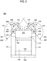
- FIG. 2 is a schematic top view showing an obstacle detection range of electrically powered wheelchair 100 according to Embodiment 1.
- footrest frame 111 is omitted in order to illustrate the detection range easily.
- electrically powered wheelchair 100 of Embodiment 1 at least has seat frame 107, seat back frame 109, footrest frame 111, wheel section 112, and obstacle detection sensor 124.
- Wheel section 112 is configured of pair of right and left drive wheels 102 rotatably attached to main frame 101 and pair of right and left auxiliary wheels 105 provided as steered wheels.
- Main frame 101 is supported by drive wheels 102 and auxiliary wheels 105.
- Seat frame 107 is disposed above main frame 101, and supports sitting seat 106 that supports buttocks and thighs of the user.
- Seat back frame 109 is disposed so as to be erected diagonally backward and upward of main frame 101.
- Seat back frame 109 supports backrest 108 that supports back of the user.
- Footrest frame 111 is inclined diagonally downward at the front of main frame 101 and formed in an L-shape. Footrest frame 111 supports footrest 110 that supports feet of the user.
- Electrically powered wheelchair 100 may have actuator 121 and actuator 122 in order to adjust respective angles of seat frame 107, seat back frame 109, and footrest frame 111.
- sitting seat 106 supports the buttocks and thighs of the user
- backrest 108 supports the back of the user
- footrest 110 supports the feet of the user, so that the user can use electrically powered wheelchair 100 in a sitting state.
- Obstacle detection sensor 124 detects an obstacle in front of electrically powered wheelchair 100 when the electrically powered wheelchair is moving so that traveling of electrically powered wheelchair 100 is not hindered.
- One obstacle detection sensor 124 may be installed at the back side of footrest 110, but in FIG. 2 , two obstacle detection sensors 124 are installed as an example.
- obstacle detection sensor 124 is disposed on each side of electrically powered wheelchair 100, at a position in front of seat frame 107 and a side of seat frame 107 than front end 600 of footrest frame 111.
- Obstacle detection sensor 124 detects an obstacle within sensing range 291 on the front side of electrically powered wheelchair 100.
- Sensing range 291 of obstacle detection sensor 124 that detects an obstacle is a semicircular planar shape region inclined with respect to a front-rear direction of electrically powered wheelchair 100 in FIG. 2 .
- Obstacle detection sensor 124 is installed in front of seat frame 107 and on a side of seat frame 107 than front end 600 of footrest frame 111 that supports feet 500 of the user. According to the configuration, electrically powered wheelchair 100 can avoid detection of unwanted obstacles such as feet 500 of the user which should not to be detected.
- Electrically powered wheelchair 100 may have pair of electrically powered motors 103 to drive pair of drive wheels 102, a battery (not shown) to drive pair of electrically powered motors 103, and controller 104 in main frame 101. Controller 104 independently drives and controls each pair of electrically powered motors 103 to control the movement of electrically powered wheelchair 100.
- obstacle detection sensor 124 is installed on each side of electrically powered wheelchair 100, at a position in front of seat frame 107 and a side of seat frame 107 than front end 600 of footrest frame 111.
- Electrically powered wheelchair 100 may have sensor base 123 that projects in a rectangular parallelepiped shape in the front-rear direction, on each side of footrest frame 111 and at a front end of main frame 101. That is, a rear end of sensor base 123 is fixed at the front end of main frame 101, and obstacle detection sensor 124 may be supported on sensor base 123.
- obstacle detection sensor 124 By fixing sensor base 123 on which obstacle detection sensor 124 installed at main frame 101, it is possible to dispose obstacle detection sensor 124 at a position that is reliably in front of seat frame 107 by a length of sensor base 123 and a side of seat frame 107 than front end 600 of footrest frame 111. Therefore, it is possible to further reliably avoid the detection of unwanted obstacles such as the feet of the user.
- FIG. 3 is a schematic top view of electrically powered wheelchair 100 and a user according to Embodiment 1.
- the calves are the thickest. Since the length of the calves are approximately 13 cm in general, it is possible to avoid false detection of the feet of the user by installing obstacle detection sensor 124 approximately 13 cm in front of footrest 110 (see arrow 150 in FIG. 3 ).
- obstacle detection sensor 124 approximately 18 cm in front of footrest 110. With this configuration, false detection of the feet of the user can be more reliably avoided.
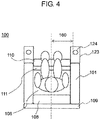
- FIG. 4 is a schematic top view of electrically powered wheelchair 100 and the user according to Embodiment 1.
- FIG. 4 describes the right-left direction of obstacle detection sensor 124.
- obstacle detection sensor 124 13 cm or more outside from a lateral symmetry axis of electrically powered wheelchair 100 (see arrow 160 of FIG. 4 ).
- the width of electrically powered wheelchair 100 may be as narrower as possible to an extent that a person can sit. Accordingly, it is desirable that a position where obstacle detection sensor 124 is installed is located inside the outermost periphery of electrically powered wheelchair 100.
- FIG. 5 is a schematic side view of electrically powered wheelchair 100 and the user according to Embodiment 1.
- Obstacle detection sensor 124 needs to be installed above a bottom surface of footrest frame 111 for putting feet when sitting. By locating at this position, it is possible to avoid falsely detecting footrest frame 111 itself. Moreover, considering the sitting state, obstacle detection sensor 124 can more reliably avoid the false detection of an instep of the user by installing obstacle detection sensor 124 at a higher position by the height of the instep. General height of the instep is approximately 10 cm. Therefore, it is desirable to install obstacle detection sensor 124 10 cm or higher than footrest frame 111.
- electrically powered wheelchair 100 may further have flat plate-shaped foot covers 125 that restrict disposal range of feet 500 of the user, one at each position in front of sensor bases 123 on both sides of electrically powered wheelchair 100.
- foot cover 125 in foot cover 125, the rear end of foot cover 125 is rotationally supported by the front end of sensor base 123 within an angle range along a lateral direction, and rotatable within the angle range.
- the angle range is a rotation range between retract position 295 where there is no problem for the user to get on or get off electrically powered wheelchair 100 and regulation position 294 that is regulated by foot cover 125 so that foot 500 of the user does not fall within sensing range 291 of obstacle detection sensor 124.
- retract position 295 means, for example, a position of a dashed line along the front-rear direction of electrically powered wheelchair 100 in FIG. 2 .
- Regulation position 294 means, for example, a solid line position in FIG. 2 .
- obstacle detection sensor 124 performs detection
- obstacle detection sensor 124 performs detection is, for example, when the user rides on electrically powered wheelchair 100 and drives electrically powered wheelchair 100. Accordingly, it is possible to regulate feet 500 of the user so as not to fall within sensing range 291 of obstacle detection sensor 124 by foot cover 125.
- Obstacle detection sensors 124 are installed on sensor bases 123 fixed on the front end side of main frame 101, and obstacle detection ranges (sensing ranges) 291 of obstacle detection sensors 124 disposed one on each side of electrically powered wheelchair 100 are set so as to overlap in front of electrically powered wheelchair 100.
- Foot cover 125 may be supported by sensor base 123 such that foot cover 125 rotates between regulation position 294 and retract position 295 around central axis 293 that is substantially coincident with a position where obstacle detection sensor 124 is fixed to sensor base 123.
- obstacle detection sensor 124 can be disposed in front of footrest 110 by the length of sensor base 123. As indicated by a dashed line in FIG. 2 , since seat frame 107 is disposed behind footrest 110, obstacle detection sensor 124 is disposed in front of seat frame 107. In a case where the user rides on and uses electrically powered wheelchair 100, the buttocks and thighs of the user is supported by seat frame 107, and feet 500 of the user is supported by footrest 110 and footrest frame 111.
- obstacle detection sensor 124 is positioned in front of seat frame 107 and a side of seat frame 107 than front end 600 of footrest frame 111, the possibility of obstacle detection sensor 124 falsely detecting feet 500 of the user as an obstacle becomes very low.
- foot cover 125 can be rotated from retract position 295 to regulation position 294 on central axis 293 (rotation axis) having the same substantially coincident central axis at a position where obstacle detection sensor 124 is fixed to sensor base 123. Accordingly, it is possible to make boundary 292 of sensing range 291 of obstacle detection sensor 124 to substantially match with the position of foot cover 125 (see regulation position 294 of foot cover 125 of solid line in FIG. 2 ). As a result, it is possible to effectively restrict feet 500 of the user not to protrude into a region of sensing range 291.
- obstacle detection sensor 124 can be installed at a position in front of seat frame 107 and a side of seat frame 107 than front end 600 of side footrest frame 111, and can efficiently restrict feet 500 of the user not to protrude into a region of sensing range 291, with provided foot cover 125. Accordingly, it is possible to eliminate the false detection of an object which should not be detected as an obstacle, such as feet 500 of the user.
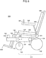
- FIG. 6 is a schematic side view of electrically powered wheelchair 300 according to Embodiment 2.
- FIG. 7 is a schematic top view showing an obstacle detection range of electrically powered wheelchair 300 according to Embodiment 2.
- the basic configuration of electrically powered wheelchair 300 is the same as the configuration of electrically powered wheelchair 100 in FIG. 1 .
- Electrically powered wheelchair 300 further includes operation lever 301 and arm rest 302 in addition to the configuration of electrically powered wheelchair 100 of FIG. 1 .
- operation lever 301 and arm rest 302 in addition to the configuration of electrically powered wheelchair 100 of FIG. 1 .
- Embodiment 2 the description of the same configuration and operation as in FIG. 1 will be omitted.
- Operation lever 301 is connected with controller 104. Pair of electrically powered motors 103 are controlled so as to move electrically powered wheelchair 300 in a swinging direction (traveling direction) by swinging operation lever 301 back and forth and right and left.
- controller 104 controls electrically powered motor 103 to move electrically powered wheelchair 300 in the same direction as the direction applied to operation lever 301.
- Pair of electrically powered motors 103 rotationally drive pair of drive wheels 102 in forward and reverse directions to move electrically powered wheelchair 300.
- Obstacle detection sensors 124 that detect an obstacle are installed on sensor bases 323 that project in the front-rear direction, for example, in a rectangular parallelepiped shape on both sides of footrest frame 111 and the front end of main frame 101. As shown in FIG. 7 , the rear end of sensor base 323 is rotatably supported around rotation axis 324 in the right-left direction with respect to the front end of main frame 101. Sensor base 323 is rotationally driven by motor 325 for rotation of sensor base that functions as an example of a rotation drive device so as to rotate based on a direction applied to operation lever 301 in which controller 104 detected.
- controller 104 moves sensor base 323 on the same side with the direction of the movement component to an outside of electrically powered wheelchair 300, and enables the detection range of an obstacle to be extended behind electrically powered wheelchair 300.
- FIG. 7 shows a top view of electrically powered wheelchair 300.
- controller 104 detects a left side component as a component applied to operation lever 301.
- motor 325 for rotation of sensor base on the left side is rotationally driven and controlled by controller 104 to rotate sensor base 323 on the left side of electrically powered wheelchair 300 around rotation axis 324 to the left side which is the outside of electrically powered wheelchair 300 by angle ⁇ 2.
- sensing range 291 of obstacle detection sensor 124 can be rotationally moved backward by angle ⁇ 2 ( ⁇ 1) to obtain changed sensing range 491.
- ⁇ 1 the angle formed between boundary 292 of sensing range 291 before the rotation of sensor base 323 and the front-rear direction of electrically powered wheelchair 300.
- obstacle detection sensor 124 it is possible to use a laser sensor in general, but a time of flight (TOF) sensor may also be used. In this case, it is possible to lower the cost of electrically powered wheelchair 300 compared to the case where a laser sensor is used. Also, a stereo camera may be used. In this case, since it is possible to obtain color information in addition to information on depth, it is possible to obtain more detailed information on the obstacle, and to realize accurate obstacle avoidance.
- TOF time of flight
- sensor base 323 and foot cover 125 can be combined. According to the combination, obstacle detection sensor 124 can avoid false detection of feet 500 of the user as an obstacle in addition to the above-described effect of the sensor base 323 at the same time.
- Embodiment 2 it is possible to move sensor base 323 that supports obstacle detection sensor 124 to the outside of electrically powered wheelchair 300 according to the direction applied to operation lever 301. Accordingly, in a case where electrically powered wheelchair 300 is moved to right and left, it is possible to detect an obstacle on the right and left side and at the back with single obstacle detection sensor 124. As a result, it is possible to avoid the risk of collision against an obstacle without installing additional sensors.
- the electrically powered wheelchair of the present disclosure can avoid detection of unwanted obstacles such as feet of the user by installing the obstacle detection sensor at a position in front of the seat frame. As a result, it is useful as an electrically powered wheelchair to be used in areas requiring indoor and outdoor movement such as nursing care or welfare fields.
Landscapes
- Health & Medical Sciences (AREA)
- Life Sciences & Earth Sciences (AREA)
- Animal Behavior & Ethology (AREA)
- General Health & Medical Sciences (AREA)
- Public Health (AREA)
- Veterinary Medicine (AREA)
- Electric Propulsion And Braking For Vehicles (AREA)
- Handcart (AREA)
Applications Claiming Priority (2)
| Application Number | Priority Date | Filing Date | Title |
|---|---|---|---|
| JP2016125723 | 2016-06-24 | ||
| PCT/JP2017/021406 WO2017221736A1 (fr) | 2016-06-24 | 2017-06-09 | Fauteuil roulant électrique |
Publications (3)
| Publication Number | Publication Date |
|---|---|
| EP3449885A1 true EP3449885A1 (fr) | 2019-03-06 |
| EP3449885A4 EP3449885A4 (fr) | 2019-05-08 |
| EP3449885B1 EP3449885B1 (fr) | 2020-12-16 |
Family
ID=60784458
Family Applications (1)
| Application Number | Title | Priority Date | Filing Date |
|---|---|---|---|
| EP17815205.4A Active EP3449885B1 (fr) | 2016-06-24 | 2017-06-09 | Fauteuil roulant électrique |
Country Status (5)
| Country | Link |
|---|---|
| US (1) | US10646387B2 (fr) |
| EP (1) | EP3449885B1 (fr) |
| JP (1) | JP6278169B1 (fr) |
| CN (1) | CN109414363B (fr) |
| WO (1) | WO2017221736A1 (fr) |
Families Citing this family (5)
| Publication number | Priority date | Publication date | Assignee | Title |
|---|---|---|---|---|
| NL2018934B1 (en) * | 2017-05-17 | 2018-11-28 | Vekoma Rides Eng B V | Amusement device seat assembly including leg locking device. |
| JP6740190B2 (ja) * | 2017-08-03 | 2020-08-12 | 株式会社エクセディ | 移動装置 |
| JP6967444B2 (ja) * | 2017-12-22 | 2021-11-17 | パナソニック株式会社 | 移動車両 |
| JP6687234B2 (ja) * | 2018-03-05 | 2020-04-22 | 株式会社エクセディ | 移動装置 |
| JP2021119975A (ja) * | 2019-03-29 | 2021-08-19 | ピクシーダストテクノロジーズ株式会社 | 電動車椅子、車椅子制御装置、電動車椅子制御方法及び電動車椅子制御プログラム |
Family Cites Families (36)
| Publication number | Priority date | Publication date | Assignee | Title |
|---|---|---|---|---|
| US4192546A (en) * | 1978-08-07 | 1980-03-11 | Smith Margaret B | Wheelchair abduction pillow |
| GB2249287B (en) * | 1990-11-01 | 1994-09-14 | Nicholas Ewart Edmund | Wheelchair |
| JP3389940B2 (ja) * | 1995-02-21 | 2003-03-24 | 株式会社アテックス | 車いすのフットレスト収納装置 |
| US5713591A (en) * | 1995-09-29 | 1998-02-03 | Zarkhin; Gregory | Multiposition leg and foot, arm and hand supports for wheelchairs |
| JP2002238951A (ja) * | 2001-02-21 | 2002-08-27 | Takara Sangyo Kk | 車椅子用保護カバー |
| JP2003334218A (ja) * | 2002-05-22 | 2003-11-25 | Matsushita Electric Ind Co Ltd | 電動車椅子 |
| US6842692B2 (en) * | 2002-07-02 | 2005-01-11 | The United States Of America As Represented By The Department Of Veterans Affairs | Computer-controlled power wheelchair navigation system |
| JP4590632B2 (ja) * | 2005-01-06 | 2010-12-01 | 国立大学法人広島大学 | 車椅子電動化装置 |
| CN101190158B (zh) * | 2006-11-29 | 2010-12-01 | 上海电气集团股份有限公司 | 智能轮椅 |
| US20110130940A1 (en) * | 2008-05-23 | 2011-06-02 | Foundacion Fatronik | Wheelchair and method for correcting the guidance of a wheelchair |
| US8280561B2 (en) * | 2008-09-09 | 2012-10-02 | University Health Network | Powered wheelchair |
| US20100095459A1 (en) * | 2008-10-20 | 2010-04-22 | Lambert Glynn D | Pillow for use with wheelchair |
| JP5316142B2 (ja) | 2009-03-23 | 2013-10-16 | トヨタ自動車株式会社 | 倒立車輪型移動体 |
| JP5186041B2 (ja) * | 2009-06-02 | 2013-04-17 | パナソニック株式会社 | 電動車両、及び、制御方法 |
| JP2011177205A (ja) | 2010-02-26 | 2011-09-15 | Quest Engineering:Kk | 電動車椅子の走行制御方法 |
| CN101923345A (zh) * | 2010-09-10 | 2010-12-22 | 天津科技大学 | 电动轮椅智能控制系统 |
| JP5161353B2 (ja) * | 2010-10-19 | 2013-03-13 | パナソニック株式会社 | 電動車両及びその制御方法 |
| CN201847848U (zh) * | 2010-11-09 | 2011-06-01 | 淮安市滨湖机械有限公司 | 前向障碍自动停车的电动轮椅 |
| DE112011105204T5 (de) | 2011-05-31 | 2014-07-03 | Hitachi, Ltd. | Autonomes Bewegungssystem |
| WO2013021546A1 (fr) | 2011-08-08 | 2013-02-14 | パナソニック株式会社 | Véhicule électrique et son procédé de commande |
| US9044369B2 (en) * | 2011-11-04 | 2015-06-02 | The United States Of America, As Represented By The Department Of Veterans Affairs | Mobile manual standing wheelchair |
| US8882129B2 (en) * | 2011-12-27 | 2014-11-11 | R We Having Fun Yet, Llc | Leg support assembly for use with a wheelchair and methods of assembling same |
| CN102600026A (zh) * | 2012-03-09 | 2012-07-25 | 常州汉迪机器人科技有限公司 | 全向智能电动轮椅 |
| JP2014191485A (ja) | 2013-03-26 | 2014-10-06 | Sharp Corp | 障害物検出装置、及びそれを備えた電動車両 |
| CN103263324B (zh) * | 2013-05-06 | 2015-07-22 | 西安电子科技大学 | 基于ssvep稳态视觉诱发电位的智能轮椅系统 |
| CN203291128U (zh) * | 2013-05-06 | 2013-11-20 | 浙江大学 | 一种基于生物电多模态控制的智能避障轮椅 |
| TWI542339B (zh) * | 2013-12-12 | 2016-07-21 | dun-ji Li | Wheelchair equipment and systems for self care |
| JP6326240B2 (ja) * | 2014-02-14 | 2018-05-16 | アイシン精機株式会社 | 移動体及びその最高速度の制御方法 |
| CN104000694A (zh) * | 2014-05-27 | 2014-08-27 | 上海交通大学 | 电动轮椅辅助驾驶系统及方法 |
| JP6248829B2 (ja) * | 2014-07-01 | 2017-12-20 | 株式会社豊田自動織機 | 電動車両 |
| JP2016043111A (ja) * | 2014-08-25 | 2016-04-04 | スズキ株式会社 | 小型電動車両 |
| JP2016052374A (ja) * | 2014-09-03 | 2016-04-14 | 株式会社国際電気通信基礎技術研究所 | 移動体および情報提示方法 |
| CN104434428A (zh) * | 2014-11-07 | 2015-03-25 | 济宁中科先进技术研究院有限公司 | 新型的智能轮椅 |
| CN204306992U (zh) * | 2014-12-15 | 2015-05-06 | 兰州理工大学 | 智能语音识别助残轮椅装置 |
| TWI551495B (zh) * | 2015-05-15 | 2016-10-01 | Merits Health Products Co Ltd | Scooter leg lift device |
| CN205054634U (zh) * | 2015-08-28 | 2016-03-02 | 深圳市尚荣医用工程有限公司 | 一种障碍自识别智能导航轮椅 |
-
2017
- 2017-06-09 JP JP2017557213A patent/JP6278169B1/ja active Active
- 2017-06-09 EP EP17815205.4A patent/EP3449885B1/fr active Active
- 2017-06-09 WO PCT/JP2017/021406 patent/WO2017221736A1/fr not_active Ceased
- 2017-06-09 US US16/306,928 patent/US10646387B2/en active Active
- 2017-06-09 CN CN201780038207.XA patent/CN109414363B/zh active Active
Also Published As
| Publication number | Publication date |
|---|---|
| WO2017221736A1 (fr) | 2017-12-28 |
| EP3449885B1 (fr) | 2020-12-16 |
| CN109414363A (zh) | 2019-03-01 |
| JP6278169B1 (ja) | 2018-02-14 |
| EP3449885A4 (fr) | 2019-05-08 |
| US10646387B2 (en) | 2020-05-12 |
| CN109414363B (zh) | 2020-02-18 |
| US20190142660A1 (en) | 2019-05-16 |
| JPWO2017221736A1 (ja) | 2018-06-21 |
Similar Documents
| Publication | Publication Date | Title |
|---|---|---|
| EP3449885B1 (fr) | Fauteuil roulant électrique | |
| KR102278027B1 (ko) | 전동 휠체어 및 그 제어방법 | |
| EP2862553B1 (fr) | Véhicule propulsé manuellement | |
| KR102277565B1 (ko) | 전동 휠체어 및 그 제어방법 | |
| KR102275618B1 (ko) | 전동 휠체어 및 그 제어방법 | |
| KR101440054B1 (ko) | 전동휠체어 및 그 제어 방법 | |
| JP6309297B2 (ja) | 電動モビリティおよびその制御方法 | |
| EP3730114B1 (fr) | Véhicule mobile | |
| JP7100928B2 (ja) | 電動車椅子、車椅子制御装置、電動車椅子制御方法及び電動車椅子制御プログラム | |
| JP6326240B2 (ja) | 移動体及びその最高速度の制御方法 | |
| JP6796499B2 (ja) | 電動車いす | |
| EP4653233A1 (fr) | Système d'évitement de collision pour trottinette mobile | |
| US8522908B1 (en) | Photoelectric-activated switch for a motorized wheelchair | |
| JP6248829B2 (ja) | 電動車両 | |
| JP6846692B2 (ja) | 電動車いす | |
| KR20150041419A (ko) | 전동식 회전 휠체어 | |
| JP2014073806A (ja) | 電動モビリティ | |
| JP7108732B2 (ja) | 方向転換補助装置 | |
| KR20180047198A (ko) | 스마트 전동 체어 | |
| JP2014073316A (ja) | 電動モビリティ | |
| JP6709989B2 (ja) | 電動車いす | |
| JP2016073386A (ja) | バランス訓練機 | |
| JP6233266B2 (ja) | バランス訓練機 | |
| KR20250082562A (ko) | 자율주행 휠체어 및 그 제어방법 | |
| JP2004358171A (ja) | 室内用電動車椅子 |
Legal Events
| Date | Code | Title | Description |
|---|---|---|---|
| STAA | Information on the status of an ep patent application or granted ep patent |
Free format text: STATUS: THE INTERNATIONAL PUBLICATION HAS BEEN MADE |
|
| PUAI | Public reference made under article 153(3) epc to a published international application that has entered the european phase |
Free format text: ORIGINAL CODE: 0009012 |
|
| STAA | Information on the status of an ep patent application or granted ep patent |
Free format text: STATUS: REQUEST FOR EXAMINATION WAS MADE |
|
| 17P | Request for examination filed |
Effective date: 20181129 |
|
| AK | Designated contracting states |
Kind code of ref document: A1 Designated state(s): AL AT BE BG CH CY CZ DE DK EE ES FI FR GB GR HR HU IE IS IT LI LT LU LV MC MK MT NL NO PL PT RO RS SE SI SK SM TR |
|
| AX | Request for extension of the european patent |
Extension state: BA ME |
|
| A4 | Supplementary search report drawn up and despatched |
Effective date: 20190410 |
|
| RIC1 | Information provided on ipc code assigned before grant |
Ipc: A61G 5/10 20060101ALI20190404BHEP Ipc: A61G 5/04 20130101AFI20190404BHEP |
|
| DAV | Request for validation of the european patent (deleted) | ||
| DAX | Request for extension of the european patent (deleted) | ||
| STAA | Information on the status of an ep patent application or granted ep patent |
Free format text: STATUS: EXAMINATION IS IN PROGRESS |
|
| 17Q | First examination report despatched |
Effective date: 20200123 |
|
| GRAP | Despatch of communication of intention to grant a patent |
Free format text: ORIGINAL CODE: EPIDOSNIGR1 |
|
| STAA | Information on the status of an ep patent application or granted ep patent |
Free format text: STATUS: GRANT OF PATENT IS INTENDED |
|
| INTG | Intention to grant announced |
Effective date: 20200817 |
|
| GRAS | Grant fee paid |
Free format text: ORIGINAL CODE: EPIDOSNIGR3 |
|
| GRAA | (expected) grant |
Free format text: ORIGINAL CODE: 0009210 |
|
| STAA | Information on the status of an ep patent application or granted ep patent |
Free format text: STATUS: THE PATENT HAS BEEN GRANTED |
|
| AK | Designated contracting states |
Kind code of ref document: B1 Designated state(s): AL AT BE BG CH CY CZ DE DK EE ES FI FR GB GR HR HU IE IS IT LI LT LU LV MC MK MT NL NO PL PT RO RS SE SI SK SM TR |
|
| REG | Reference to a national code |
Ref country code: GB Ref legal event code: FG4D |
|
| REG | Reference to a national code |
Ref country code: DE Ref legal event code: R096 Ref document number: 602017029766 Country of ref document: DE |
|
| REG | Reference to a national code |
Ref country code: IE Ref legal event code: FG4D |
|
| REG | Reference to a national code |
Ref country code: AT Ref legal event code: REF Ref document number: 1344912 Country of ref document: AT Kind code of ref document: T Effective date: 20210115 |
|
| REG | Reference to a national code |
Ref country code: NL Ref legal event code: FP |
|
| PG25 | Lapsed in a contracting state [announced via postgrant information from national office to epo] |
Ref country code: NO Free format text: LAPSE BECAUSE OF FAILURE TO SUBMIT A TRANSLATION OF THE DESCRIPTION OR TO PAY THE FEE WITHIN THE PRESCRIBED TIME-LIMIT Effective date: 20210316 Ref country code: GR Free format text: LAPSE BECAUSE OF FAILURE TO SUBMIT A TRANSLATION OF THE DESCRIPTION OR TO PAY THE FEE WITHIN THE PRESCRIBED TIME-LIMIT Effective date: 20210317 Ref country code: RS Free format text: LAPSE BECAUSE OF FAILURE TO SUBMIT A TRANSLATION OF THE DESCRIPTION OR TO PAY THE FEE WITHIN THE PRESCRIBED TIME-LIMIT Effective date: 20201216 Ref country code: FI Free format text: LAPSE BECAUSE OF FAILURE TO SUBMIT A TRANSLATION OF THE DESCRIPTION OR TO PAY THE FEE WITHIN THE PRESCRIBED TIME-LIMIT Effective date: 20201216 |
|
| REG | Reference to a national code |
Ref country code: AT Ref legal event code: MK05 Ref document number: 1344912 Country of ref document: AT Kind code of ref document: T Effective date: 20201216 |
|
| PG25 | Lapsed in a contracting state [announced via postgrant information from national office to epo] |
Ref country code: SE Free format text: LAPSE BECAUSE OF FAILURE TO SUBMIT A TRANSLATION OF THE DESCRIPTION OR TO PAY THE FEE WITHIN THE PRESCRIBED TIME-LIMIT Effective date: 20201216 Ref country code: LV Free format text: LAPSE BECAUSE OF FAILURE TO SUBMIT A TRANSLATION OF THE DESCRIPTION OR TO PAY THE FEE WITHIN THE PRESCRIBED TIME-LIMIT Effective date: 20201216 Ref country code: BG Free format text: LAPSE BECAUSE OF FAILURE TO SUBMIT A TRANSLATION OF THE DESCRIPTION OR TO PAY THE FEE WITHIN THE PRESCRIBED TIME-LIMIT Effective date: 20210316 |
|
| PG25 | Lapsed in a contracting state [announced via postgrant information from national office to epo] |
Ref country code: HR Free format text: LAPSE BECAUSE OF FAILURE TO SUBMIT A TRANSLATION OF THE DESCRIPTION OR TO PAY THE FEE WITHIN THE PRESCRIBED TIME-LIMIT Effective date: 20201216 |
|
| REG | Reference to a national code |
Ref country code: LT Ref legal event code: MG9D |
|
| PG25 | Lapsed in a contracting state [announced via postgrant information from national office to epo] |
Ref country code: SK Free format text: LAPSE BECAUSE OF FAILURE TO SUBMIT A TRANSLATION OF THE DESCRIPTION OR TO PAY THE FEE WITHIN THE PRESCRIBED TIME-LIMIT Effective date: 20201216 Ref country code: RO Free format text: LAPSE BECAUSE OF FAILURE TO SUBMIT A TRANSLATION OF THE DESCRIPTION OR TO PAY THE FEE WITHIN THE PRESCRIBED TIME-LIMIT Effective date: 20201216 Ref country code: PT Free format text: LAPSE BECAUSE OF FAILURE TO SUBMIT A TRANSLATION OF THE DESCRIPTION OR TO PAY THE FEE WITHIN THE PRESCRIBED TIME-LIMIT Effective date: 20210416 Ref country code: SM Free format text: LAPSE BECAUSE OF FAILURE TO SUBMIT A TRANSLATION OF THE DESCRIPTION OR TO PAY THE FEE WITHIN THE PRESCRIBED TIME-LIMIT Effective date: 20201216 Ref country code: LT Free format text: LAPSE BECAUSE OF FAILURE TO SUBMIT A TRANSLATION OF THE DESCRIPTION OR TO PAY THE FEE WITHIN THE PRESCRIBED TIME-LIMIT Effective date: 20201216 Ref country code: EE Free format text: LAPSE BECAUSE OF FAILURE TO SUBMIT A TRANSLATION OF THE DESCRIPTION OR TO PAY THE FEE WITHIN THE PRESCRIBED TIME-LIMIT Effective date: 20201216 Ref country code: CZ Free format text: LAPSE BECAUSE OF FAILURE TO SUBMIT A TRANSLATION OF THE DESCRIPTION OR TO PAY THE FEE WITHIN THE PRESCRIBED TIME-LIMIT Effective date: 20201216 |
|
| PG25 | Lapsed in a contracting state [announced via postgrant information from national office to epo] |
Ref country code: PL Free format text: LAPSE BECAUSE OF FAILURE TO SUBMIT A TRANSLATION OF THE DESCRIPTION OR TO PAY THE FEE WITHIN THE PRESCRIBED TIME-LIMIT Effective date: 20201216 Ref country code: AT Free format text: LAPSE BECAUSE OF FAILURE TO SUBMIT A TRANSLATION OF THE DESCRIPTION OR TO PAY THE FEE WITHIN THE PRESCRIBED TIME-LIMIT Effective date: 20201216 |
|
| REG | Reference to a national code |
Ref country code: DE Ref legal event code: R097 Ref document number: 602017029766 Country of ref document: DE |
|
| PG25 | Lapsed in a contracting state [announced via postgrant information from national office to epo] |
Ref country code: IS Free format text: LAPSE BECAUSE OF FAILURE TO SUBMIT A TRANSLATION OF THE DESCRIPTION OR TO PAY THE FEE WITHIN THE PRESCRIBED TIME-LIMIT Effective date: 20210416 |
|
| PLBE | No opposition filed within time limit |
Free format text: ORIGINAL CODE: 0009261 |
|
| STAA | Information on the status of an ep patent application or granted ep patent |
Free format text: STATUS: NO OPPOSITION FILED WITHIN TIME LIMIT |
|
| PG25 | Lapsed in a contracting state [announced via postgrant information from national office to epo] |
Ref country code: IT Free format text: LAPSE BECAUSE OF FAILURE TO SUBMIT A TRANSLATION OF THE DESCRIPTION OR TO PAY THE FEE WITHIN THE PRESCRIBED TIME-LIMIT Effective date: 20201216 Ref country code: AL Free format text: LAPSE BECAUSE OF FAILURE TO SUBMIT A TRANSLATION OF THE DESCRIPTION OR TO PAY THE FEE WITHIN THE PRESCRIBED TIME-LIMIT Effective date: 20201216 |
|
| 26N | No opposition filed |
Effective date: 20210917 |
|
| PG25 | Lapsed in a contracting state [announced via postgrant information from national office to epo] |
Ref country code: DK Free format text: LAPSE BECAUSE OF FAILURE TO SUBMIT A TRANSLATION OF THE DESCRIPTION OR TO PAY THE FEE WITHIN THE PRESCRIBED TIME-LIMIT Effective date: 20201216 |
|
| REG | Reference to a national code |
Ref country code: DE Ref legal event code: R119 Ref document number: 602017029766 Country of ref document: DE |
|
| PG25 | Lapsed in a contracting state [announced via postgrant information from national office to epo] |
Ref country code: MC Free format text: LAPSE BECAUSE OF FAILURE TO SUBMIT A TRANSLATION OF THE DESCRIPTION OR TO PAY THE FEE WITHIN THE PRESCRIBED TIME-LIMIT Effective date: 20201216 Ref country code: ES Free format text: LAPSE BECAUSE OF FAILURE TO SUBMIT A TRANSLATION OF THE DESCRIPTION OR TO PAY THE FEE WITHIN THE PRESCRIBED TIME-LIMIT Effective date: 20201216 |
|
| REG | Reference to a national code |
Ref country code: CH Ref legal event code: PL |
|
| GBPC | Gb: european patent ceased through non-payment of renewal fee |
Effective date: 20210609 |
|
| PG25 | Lapsed in a contracting state [announced via postgrant information from national office to epo] |
Ref country code: SI Free format text: LAPSE BECAUSE OF FAILURE TO SUBMIT A TRANSLATION OF THE DESCRIPTION OR TO PAY THE FEE WITHIN THE PRESCRIBED TIME-LIMIT Effective date: 20201216 |
|
| REG | Reference to a national code |
Ref country code: BE Ref legal event code: MM Effective date: 20210630 |
|
| PG25 | Lapsed in a contracting state [announced via postgrant information from national office to epo] |
Ref country code: LU Free format text: LAPSE BECAUSE OF NON-PAYMENT OF DUE FEES Effective date: 20210609 |
|
| PG25 | Lapsed in a contracting state [announced via postgrant information from national office to epo] |
Ref country code: LI Free format text: LAPSE BECAUSE OF NON-PAYMENT OF DUE FEES Effective date: 20210630 Ref country code: IE Free format text: LAPSE BECAUSE OF NON-PAYMENT OF DUE FEES Effective date: 20210609 Ref country code: GB Free format text: LAPSE BECAUSE OF NON-PAYMENT OF DUE FEES Effective date: 20210609 Ref country code: DE Free format text: LAPSE BECAUSE OF NON-PAYMENT OF DUE FEES Effective date: 20220101 Ref country code: CH Free format text: LAPSE BECAUSE OF NON-PAYMENT OF DUE FEES Effective date: 20210630 |
|
| PG25 | Lapsed in a contracting state [announced via postgrant information from national office to epo] |
Ref country code: IS Free format text: LAPSE BECAUSE OF FAILURE TO SUBMIT A TRANSLATION OF THE DESCRIPTION OR TO PAY THE FEE WITHIN THE PRESCRIBED TIME-LIMIT Effective date: 20210416 Ref country code: FR Free format text: LAPSE BECAUSE OF NON-PAYMENT OF DUE FEES Effective date: 20210630 |
|
| PG25 | Lapsed in a contracting state [announced via postgrant information from national office to epo] |
Ref country code: BE Free format text: LAPSE BECAUSE OF NON-PAYMENT OF DUE FEES Effective date: 20210630 |
|
| PG25 | Lapsed in a contracting state [announced via postgrant information from national office to epo] |
Ref country code: CY Free format text: LAPSE BECAUSE OF FAILURE TO SUBMIT A TRANSLATION OF THE DESCRIPTION OR TO PAY THE FEE WITHIN THE PRESCRIBED TIME-LIMIT Effective date: 20201216 |
|
| PG25 | Lapsed in a contracting state [announced via postgrant information from national office to epo] |
Ref country code: HU Free format text: LAPSE BECAUSE OF FAILURE TO SUBMIT A TRANSLATION OF THE DESCRIPTION OR TO PAY THE FEE WITHIN THE PRESCRIBED TIME-LIMIT; INVALID AB INITIO Effective date: 20170609 |
|
| PG25 | Lapsed in a contracting state [announced via postgrant information from national office to epo] |
Ref country code: MK Free format text: LAPSE BECAUSE OF FAILURE TO SUBMIT A TRANSLATION OF THE DESCRIPTION OR TO PAY THE FEE WITHIN THE PRESCRIBED TIME-LIMIT Effective date: 20201216 |
|
| PG25 | Lapsed in a contracting state [announced via postgrant information from national office to epo] |
Ref country code: TR Free format text: LAPSE BECAUSE OF FAILURE TO SUBMIT A TRANSLATION OF THE DESCRIPTION OR TO PAY THE FEE WITHIN THE PRESCRIBED TIME-LIMIT Effective date: 20201216 |
|
| PG25 | Lapsed in a contracting state [announced via postgrant information from national office to epo] |
Ref country code: MT Free format text: LAPSE BECAUSE OF FAILURE TO SUBMIT A TRANSLATION OF THE DESCRIPTION OR TO PAY THE FEE WITHIN THE PRESCRIBED TIME-LIMIT Effective date: 20201216 |
|
| PGFP | Annual fee paid to national office [announced via postgrant information from national office to epo] |
Ref country code: NL Payment date: 20250618 Year of fee payment: 9 |