EP3450037B1 - Kontaminationsverhinderungsvorrichtung für ein system zur generativen fertigung und zugehöriges verfahren zur generativen fertigung - Google Patents
Kontaminationsverhinderungsvorrichtung für ein system zur generativen fertigung und zugehöriges verfahren zur generativen fertigung Download PDFInfo
- Publication number
- EP3450037B1 EP3450037B1 EP17189043.7A EP17189043A EP3450037B1 EP 3450037 B1 EP3450037 B1 EP 3450037B1 EP 17189043 A EP17189043 A EP 17189043A EP 3450037 B1 EP3450037 B1 EP 3450037B1
- Authority
- EP
- European Patent Office
- Prior art keywords
- prevention device
- additive manufacturing
- seal
- wall
- contamination prevention
- Prior art date
- Legal status (The legal status is an assumption and is not a legal conclusion. Google has not performed a legal analysis and makes no representation as to the accuracy of the status listed.)
- Active
Links
Images


Classifications
-
- B—PERFORMING OPERATIONS; TRANSPORTING
- B08—CLEANING
- B08B—CLEANING IN GENERAL; PREVENTION OF FOULING IN GENERAL
- B08B15/00—Preventing escape of dirt or fumes from the area where they are produced; Collecting or removing dirt or fumes from that area
- B08B15/04—Preventing escape of dirt or fumes from the area where they are produced; Collecting or removing dirt or fumes from that area from a small area, e.g. a tool
-
- B—PERFORMING OPERATIONS; TRANSPORTING
- B08—CLEANING
- B08B—CLEANING IN GENERAL; PREVENTION OF FOULING IN GENERAL
- B08B17/00—Methods preventing fouling
- B08B17/02—Preventing deposition of fouling or of dust
- B08B17/04—Preventing deposition of fouling or of dust by using removable coverings
-
- B—PERFORMING OPERATIONS; TRANSPORTING
- B33—ADDITIVE MANUFACTURING TECHNOLOGY
- B33Y—ADDITIVE MANUFACTURING, i.e. MANUFACTURING OF THREE-DIMENSIONAL [3D] OBJECTS BY ADDITIVE DEPOSITION, ADDITIVE AGGLOMERATION OR ADDITIVE LAYERING, e.g. BY 3D PRINTING, STEREOLITHOGRAPHY OR SELECTIVE LASER SINTERING
- B33Y10/00—Processes of additive manufacturing
-
- B—PERFORMING OPERATIONS; TRANSPORTING
- B33—ADDITIVE MANUFACTURING TECHNOLOGY
- B33Y—ADDITIVE MANUFACTURING, i.e. MANUFACTURING OF THREE-DIMENSIONAL [3D] OBJECTS BY ADDITIVE DEPOSITION, ADDITIVE AGGLOMERATION OR ADDITIVE LAYERING, e.g. BY 3D PRINTING, STEREOLITHOGRAPHY OR SELECTIVE LASER SINTERING
- B33Y80/00—Products made by additive manufacturing
Definitions
- the present invention relates to the field of additive manufacturing. More specifically, it relates to a contamination prevention device for additive manufacturing processes, in particular for the additive manufacturing of biological tissues or bodily members.
- Additive manufacturing which includes in particular so called 3D printing techniques, has become a fast-moving field of technology over the last decade. Long reserved for prototyping-only purposes, it has now developed to apply to almost all industries, from consumer goods and automotive to micro and nanotechnologies, medical devices and biotechnologies. In some of these industries it is even already used in commercial manufacturing, in particular for tailor-made or small to medium scale productions.
- Additive manufacturing processes generally consists in growing an object by successively depositing layers of one or several materials with a deposition system, so called 3D-printer in general.
- the deposition system comprises essentially a deposition head movable in at least two, preferably three directions of space, an object holder, which may also be movable along two or three directions of space, and a control unit.
- the control unit is arranged and programmable to drive the deposition head and/or the object holder along at three orthogonal directions of space according to a 3-dimensional digital model of the object to grow, said model being loaded in a memory of the control unit.
- the material(s) are deposited by the depositing head in a substantially melted, fluidic state, under a substantial pressure, and harden in the atmosphere after deposition or following a specific thermal co-treatment for example.
- the digital model loaded in the system accurate movement control and precision is required for the deposition head, as well as homogeneity and precision of deposition on the holder or any recipient thereon to receive the object.
- the fluidic material(s) is often deposited through a nozzle or needle having a sub-millimetre lumen and aperture diameter.
- This very small dimension at the nozzle or needle outlet combined with the great pressure required for pushing the fluid material through the latter may, depending on said material nature and viscosity, cause formation of aerosol droplets at the nozzle or needle outlet during deposition. These aerosol droplets are then projected in the deposition environment, and settle on each surface they encounter in that environment.
- contamination arising from aerosol formation during deposition is critical as it create a major risk of cross-contamination between objects grown from different biological materials, including different cells, DNAs, in a same deposition system.
- FR 2795351 A1 generally relates to devices for recovering waste or fumes generated by the execution of work into a receptacle. Particularly, this document relates to a device for recovering drilling dust.
- US 2012/0288339 A1 relates to a device making it possible to automatically collect the refuse generated at the time of drilling operations and is characterized in that it includes a receptacle made up of a deformable material comprising adhesive means laid on at least one of its external faces, wherein the adhesive means allow to fix it on the support to be bored.
- Another goal of the invention is to provide such a solution against contamination in additive manufacturing processes which is simple and cost efficient to manufacture and to use.
- a contamination prevention device as defined in claim 1, comprising a skirt defining a tubular flexible wall having a first and a second ends, said wall (3) being continuous and configured to be extensible in at least two orthogonal dimensions of space, each of said ends at least delimiting an opening and each of said ends being fitted with an elastic ring seal.
- the contamination prevention device of the invention is of extremely simple, yet convenient and efficient structure.
- the device of the invention advantageously comprises an adjustable, flexible skirt, which can be hermetically adjusted at its upper end, equipped with a first seal, about a deposition head, preferably about the deposition nozzle or needle of said head, of an additive manufacturing system and at the same time be hermetically fitted and adjusted about a sample holder or recipient where an object is manufactured through the deposition head.
- the skirt of the contamination prevention device of the invention provides a sterile field for the manufacturing of the object in the holder, delimiting a substantially hermetic volume from the deposition head to the sample holder.
- the skirt is advantageously configured to allow full freedom of movement of the deposition head during manufacturing, while at the same time preventing projection of aerosol droplets from the deposition nozzle or needle outside the volume confined by the skirt's wall. Contamination outside the skirt's wall and the seals at both ends thereof in the additive manufacturing system is hereby prevented, which cancels the need for full cleaning and sterilization between manufacturing runs, in particular for biological/biocompatible samples manufacturing.
- top end seal can be removed from the nozzle or needle one-handedly by an operator, which at the same time may hold the skirt extended to prevent falling on the manufactured sample in the holder if the skirt's wall is not rigid enough to hold onto itself.
- the tubular wall is a continuous wall, i.e. defining a plain envelope or surface between said first and second ends.
- the tubular wall may in use advantageously show a substantially conical or frusto-conical shape preferably.
- the wall is made of a substantially hermetic material.
- substantially hermetic material should be interpreted as a material that can preserve hermetic seal between the inside and outside of the contamination prevention device despite the ambient temperature.
- said hermetic material may comprise a plastic-based material, in particular from polyolefins, a rubber-based material or a silicon-based material or a combination thereof. Coated woven or non-woven materials, as well as coated paper-based material may in some cases be contemplated as well if transparency is not required.
- each of said first and second ends comprises an elastic ring seal such as an O-ring seal.
- the skirt wall may be pre-shaped.
- the wall may have an accordion-like shape.
- the pre-shaping of the skirt wall may be advantageous to confer sufficient rigidity to the contamination prevention device of the invention in order for it not to collapse under its own weight on a sample when the skirt's top end is removed from a deposition head of an additive manufacturing system.
- the invention further relates to an additive manufacturing method, wherein a contamination prevention device as previously described is used to prevent contamination between two consecutive additive manufacturing batches.
- the method of the invention advantageously comprises a step of hermetically fitting the seal at a first of said ends about a material depositing head of an additive manufacturing system and a step of hermetically fitting the seal at a second of said ends about a sample holder.
- the step of hermetically fitting the seal at a first of said ends about a material depositing head of an additive manufacturing system comprises elastically fitting the seal about said head.
- the step of hermetically fitting the seal at a second of said ends about a sample holder may further in an embodiment comprise elastically adjusting said seal about a holder's wall before manufacturing of a sample into said holder.
- the method of the invention further comprises removing the seal from said additive material deposition member of said head after a sample has been manufactured into said holder.
- the invention in accordance with claim 12, finally relates to an additive manufacturing assembly, comprising a contamination prevention device as previously described.
- said assembly comprises a biological material reservoir, preferably a syringe, and a sample holder, the seal at a first of the ends of the contamination prevention device being adjusted to the biological material reservoir and the seal at a second of said ends being adjusted to a sample holder.
- Such assembly can be manufactured and conditioned in a sterile packaging for ease of transport and security of implementation in an additive manufacturing process.
- the present invention proposes a contamination prevention device specifically configured for use in additive manufacturing techniques.
- the inventive contamination prevention device aims at preventing environmental contamination within the additive manufacturing systems during manufacturing batches to reduce the need of cleaning the systems in between batches.
- the inventive contamination prevention device finds preferred application in the prevention of cross-contamination between samples during additive manufacturing of biological and biocompatible samples and implants, such as in the bio-printing of bodily tissues such as skin or cartilaginous implants.
- Cross-contamination is indeed critical to prevent in such bio-printing processes in order to ensure viability of the samples for medical purposes, in particular implantation in patients, and most importantly to avoid biological material coming from a previous patient contaminating the sample undergoing bio-printing (thus avoiding e.g. implant rejection).
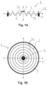
- Figures 1A and 1B represent a non-limitative example of a contamination prevention device 1 according to the invention.
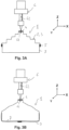
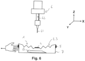
- Figures 2 to 6 further represent implementation steps of a method using the device 1 in an additive manufacturing system to prevent contamination.
- the contamination prevention device 1 essentially comprises a skirt 2 made of foldable and/or flexible material, so as to form a substantially tubular wall 3 having a first end 31 and a second end 32, said wall 3 being continuous and configured to be extensible in at least two orthogonal dimensions of space, represented in doted arrows in Figures 1A and 1B .
- the material forming wall 3 of the skirt 2 of the device is preferably a substantially hermetic material, such as an air and liquid tight material under atmospheric pressure at 25°C.
- Preferable materials for the skirt's wall 3 comprise plastic-, rubber- or silicon-based materials for example.
- the skirt 2 further comprises, at each of said wall's ends 31, 32 a seal 4, 5.
- said seals 4, 5 may comprise an elastic, ring-shapes seal, such as an O-ring seal.
- Such ring-shaped seal 4, 5 can either be integrated directly into the wall 3 and formed of a same material or attached to the wall's ends 31, 32 by any compatible method such as bonding, heat sealing or welding.
- the skirt 2 When two ring-shaped seals 4, 5 are provided at both ends 31, 32 of the wall the skirt 2 thus has two opposite open ends 31, 32 with the wall 3 extending between said ends 31, 32 and forming a tube or collar.
- one of the seals may be a plain self resealable gasket 4 while the second seal remains a ring-shaped seal 5, preferably an O-ring seal.
- the skirt 2 thus has a first closed end 31 from which extends the wall towards a second open end 32 with the wall 3 extending between said ends 31, 32 and forming a substantially conical or frusto-conical envelope.
- the provision of a plain gasket at an end 31 of wall 3 of the skirt 2 of the contamination device 1 of the invention may be preferable in some applications, in particular for additive manufacturing of biological and biocompatible samples as described in more details in relation to figures 2 to 6 .
- the opening at a largest end 32 of the skirt 2 may be configured such that it is reclosable, to allow for fully closing the wall 3 about a recipient for example, in a sachet like fashion as shown in figure 3B .
- the second end 32 may then not be fitted with a ring shape seal, but with an adhesive or magnetic seal, comprising repositionable adhesive or magnetic bands, or plastic zip locking members.
- the wall 3 of the skirt 2 is a pre-shaped wall, and more specifically an accordion like pre-shape.
- This pre-shaping of the wall 3 proves particularly advantageous as it makes the contamination prevention device 1 of the invention very compact, with a substantially regular disc shape before use, which allows for instance stacking of multiple device in a same packaging for disposable, single use purposes.
- the pre-shaping allows for flexibility and extensibility of the wall 3 of the skirt 2 even if the wall's material has some rigidity, which is required to prevent the device 1 from collapsing upon its own weight as will be described later. Rigidity can be achieved by thickening the wall 3 from a few tenth of millimetre to about 1 millimetre for example, depending on the material.
- the pre-shaping of the wall 3 to provide compressibility and flexibility thereof in multiple directions of space can result from the provision of parallel folding lines 33, which may be regularly distributed between the ends 31, 32 of the wall 3 such that said wall 3 can fold, respectively unfold, like an accordion in at least two orthogonal directions represented by the dotted arrows in figure 1A, 1B when a compressive, respectively traction, load is applied at any of said ends 31, 32.
- the contamination prevention device 1 can be used as represented in figures 2 to 6 , depicting schematically consecutive steps of an additive manufacturing method according to the invention, wherein said contamination prevention device 1 is used to prevent cross-contamination between two consecutive additive manufacturing batches or runs.
- the contamination prevention device 1 is designed for creating a confined working space in an additive manufacturing system, and more specifically a confined working space between a manufacturing head, defined as printing head 6 in the following, on the one hand, and a sample holder 7 or recipient, wherein a printed sample S is to be grown additively by the printing head 6, on the other hand.
- the printing head 6 is usually movable along two or three orthogonal directions X, Y, Z with respect to a platform onto which a sample holder 7 or recipient can be fixedly positioned.
- the platform may be movable itself along one third direction at least, perpendicularly to the two ones of the printing head 6.
- the displacements of the printing head 6 and/or platform of an additive manufacturing system are necessary to grow a sample in the three dimensions X, Y, Z in the sample holder 7 according to a digital model of the sample S.
- the displacements of the printing head 6 and/or platform are computer controlled based on the digital model of the sample S.
- the printing head 6 is mostly, in simplified terms, an extruder comprising a printing outlet, formed of a nozzle or needle 61 depending on application, and an inlet formed of or connected to a printing material reservoir, cartridge or syringe 62, the printing material being fed under pressure and at controlled temperature to the nozzle or needle 61 for extrusion and deposition in the sample holder 7.
- Contamination of the additive manufacturing environment however arises due to formation of aerosol droplets at the needle's tip, which droplets are projected in an uncontrolled manner throughout the system.
- the contamination prevention device 1 advantageously helps confining the printing head 6 and sample holder 7 in an additive manufacturing system to prevent contamination due to aerosols droplets projections during manufacturing batches.
- a first step before manufacturing of a sample is launched, the ends 31, 32 of the skirt's wall 3 are hermitically fitted by means of the seals 4, 5 about the printing head 6, preferably about the needle 61, on the one hand, and the sample holder 7, on the other hand.
- an operator manually punctures or snap fits the seal 4 at a first end 31 onto the needle 61 and then extends the end 32 and its seal 5 to adjust it about the walls of the sample holder 7.
- the seal 4 at the first end of the skirt's wall 3 may be pre-punctured to ease adjustment to the needle 61 or a blunt nozzle (not shown in the figures) where such is used for depositing the printed material.
- the sample holder's walls may be treated or conformed to improve hermetic adjustment of the seal 5 about said walls, such as with the provision of ridges or notches for seal retention, including where appropriate mating shapes thereof.
- the skirt 2 of the device 1 of the invention firmly and hermitically holds onto the needle 61 and the sample holder 7, preventing leakage of printing material along the needle 61 or sample holder's walls.
- the skirt 2 extending between said ends 31, 32 and its wall 3 forms a tubular envelope there between, which protects and prevents from projections, in particular of aerosol droplets forming at the printing head 6 to be projected in the environment of the manufacturing system.
- the contamination prevention device 1 comprises a reclosable seal 5 at its second end 32
- the skirt 2 is wrapped ( Figure 3B ) around the sample holder 7 until the reclosable seal 5 can be closed, under the bottom of the holder 7.
- the wall 3 is stretched from the needle 61 to the bottom of the holder 7.
- the manufacturing of a sample S can start, as shown in figure 4 .
- the printing head 6 is lowered in the sample holder 7 such that the needle 61 can start depositing a printing material to grow a sample S in the sample holder 7.
- the wall 3 of the skirt 2 follows the movements of the printing head 6 without interfering with its properties, such as printing precision and movement speed and accuracy.
- the pre-shaping of the wall 3 advantageously provides elasticity and prevents the wall from collapsing into the sample holder and to touch the sample S being formed therein.
- the operator can then remove the contamination prevention device 1 from the sample holder 7 outside the manufacturing system and discard it for destruction or recycling.
- the contamination prevention device 1 of the invention may advantageously be integrated in sterile conditions in a unitary printing unit comprising the contamination prevention device 1 mounted and sealed to the sample holder 7 and a syringe 62 or printing material reservoir.
- a unitary printing unit can be assembled in aseptic conditions off the additive manufacturing system where printing must be carried out and conditioned in a sterile package, which can be brought, opened and mounted by an operator to the additive manufacturing system by connecting the syringe 62 or reservoir to a pressure source of the manufacturing system.
- the connection to the pressure source will comprises inserting a sterilising filter between the filled syringe 62 and the pressure source.
- the sample can then be manufactured in a fully sterile environment.
- the sample in the unitary assembly can be removed integrally from the manufacturing system by disconnecting the syringe 62 from the pressure source of the system and resealing said syringe for transporting the unitary assembly back into an environment more suitable for biological manipulation.
- the present invention therefore provides a simple, yet effective accessory for preventing contamination during additive manufacturing batches, which is or particular importance for securing manufacturing of biological and/or biocompatible samples in particular to avoid any cross-contamination risk between two samples consecutively manufactured in a same manufacturing system.
Landscapes
- Sampling And Sample Adjustment (AREA)
Claims (14)
- Vorrichtung zur Kontaminationsverhinderung (1), umfassend eine Schürze (2), die eine röhrenförmige flexible Wand (3) mit einem ersten Ende (31) und einem zweiten Ende (32) definiert, wobei die Wand (3) durchgehend ist und dazu konfiguriert ist, in mindestens zwei orthogonale Raumdimensionen dehnbar zu sein, wobei jedes der Enden mindestens eine elastische Öffnung begrenzt und an jedem der Enden ein elastischer Dichtungsring (4, 5) angebracht ist.
- Vorrichtung zur Kontaminationsverhinderung (1) nach Anspruch 1, wobei die Wand (3) eine durchgehende Wand ist.
- Vorrichtung zur Kontaminationsverhinderung (1) nach Anspruch 1 oder 2, wobei die Wand (3) aus einem im Wesentlichen hermetischen Material hergestellt ist.
- Vorrichtung zur Kontaminationsverhinderung (1) nach einem der vorhergehenden Ansprüche, wobei die Wand (3) aus einem Kunststoff-, einem Gummi- oder einem Silikon-basierten Material hergestellt ist.
- Vorrichtung zur Kontaminationsverhinderung (1) nach einem der vorhergehenden Ansprüche, wobei die Wand (3) vorgeformt ist.
- Vorrichtung zur Kontaminationsverhinderung (1) nach einem der vorhergehenden Ansprüche, wobei die Wand (3) eine Akkordeon-artige Form aufweist.
- Vorrichtung zur Kontaminationsverhinderung (1) nach einem der Ansprüche 1 bis 6, wobei jede der Dichtungen (4, 5) ein O-Dichtungsring ist.
- Additives Herstellungsverfahren, wobei eine Vorrichtung zur Kontaminationsverhinderung (1) nach einem der Ansprüche 1 bis 7 verwendet wird, um eine Kreuzkontamination von hergestellten Proben (S) zwischen zwei aufeinanderfolgenden additiven Herstellungschargen zu verhindern, wobei das Verfahren einen Schritt eines hermetischen Anbringens der Dichtung (4) an einem ersten (31) der Enden um einen Materialablagekopf (6) eines additiven Herstellungssystems und einen Schritt eines hermetischen Anbringens der Dichtung (5) an einem zweiten (32) der Enden um einen Probenhalter (7) umfasst.
- Verfahren nach Anspruch 8, wobei der Schritt des hermetischen Anbringens der Dichtung (4) an einem ersten (31) der Enden um einen Materialablagekopf (6) eines additiven Herstellungssystems ein elastisches Anbringen der Dichtung (4) um den Kopf umfasst.
- Verfahren nach einem der Ansprüche 8 oder 9, wobei der Schritt des hermetischen Anbringens der Dichtung (5) an einem zweiten (32) der Enden um einen Probenhalter (7) ein elastisches Einstellen der Dichtung (5) um eine Halterwand vor einer Herstellung einer Probe (S) in dem Halter umfasst.
- Verfahren nach einem der Ansprüche 8 bis 10, ferner umfassend ein Entfernen der Dichtung (4) von dem additiven Materialablageelement (61) des Kopfes (6), nachdem eine Probe (S) in dem Halter (7) hergestellt worden ist.
- Additive Herstellungsanordnung, umfassend eine Vorrichtung zur Kontaminationsverhinderung (1) nach einem der Ansprüche 1 bis 7.
- Additive Herstellungsanordnung nach Anspruch 12, wobei die Dichtung (4) an einem ersten (31) der Enden der Vorrichtung zur Kontaminationsverhinderung (1) auf ein biologisches Materialreservoir (62), vorzugsweise eine Spritze, eingestellt ist, und die Dichtung (5) an einem zweiten (32) der Enden auf einen Probenhalter (7) eingestellt ist.
- Additive Herstellungsanordnung nach Anspruch 12 oder 13, die ferner in einer sterilen Verpackung konditioniert ist.
Priority Applications (5)
| Application Number | Priority Date | Filing Date | Title |
|---|---|---|---|
| DK17189043.7T DK3450037T3 (da) | 2017-09-01 | 2017-09-01 | Indretning til forebyggelse af forurening til et additivfremstillingssystem og tilsvarende fremgangsmåde til additiv fremstilling |
| PT171890437T PT3450037T (pt) | 2017-09-01 | 2017-09-01 | Dispositivo de prevenção de contaminação para um sistema de fabrico aditivo e método de fabrico aditivo correspondente |
| PL17189043.7T PL3450037T3 (pl) | 2017-09-01 | 2017-09-01 | Urządzenie zapobiegajace zanieczyszczeniom dla systemu wytwarzania przyrostowego i odpowiadający sposób wytwarzania przyrostowego |
| EP17189043.7A EP3450037B1 (de) | 2017-09-01 | 2017-09-01 | Kontaminationsverhinderungsvorrichtung für ein system zur generativen fertigung und zugehöriges verfahren zur generativen fertigung |
| ES17189043T ES2972445T3 (es) | 2017-09-01 | 2017-09-01 | Dispositivo de prevención de contaminación para un sistema de fabricación aditiva y método de fabricación aditiva correspondiente |
Applications Claiming Priority (1)
| Application Number | Priority Date | Filing Date | Title |
|---|---|---|---|
| EP17189043.7A EP3450037B1 (de) | 2017-09-01 | 2017-09-01 | Kontaminationsverhinderungsvorrichtung für ein system zur generativen fertigung und zugehöriges verfahren zur generativen fertigung |
Publications (2)
| Publication Number | Publication Date |
|---|---|
| EP3450037A1 EP3450037A1 (de) | 2019-03-06 |
| EP3450037B1 true EP3450037B1 (de) | 2024-02-07 |
Family
ID=59772466
Family Applications (1)
| Application Number | Title | Priority Date | Filing Date |
|---|---|---|---|
| EP17189043.7A Active EP3450037B1 (de) | 2017-09-01 | 2017-09-01 | Kontaminationsverhinderungsvorrichtung für ein system zur generativen fertigung und zugehöriges verfahren zur generativen fertigung |
Country Status (5)
| Country | Link |
|---|---|
| EP (1) | EP3450037B1 (de) |
| DK (1) | DK3450037T3 (de) |
| ES (1) | ES2972445T3 (de) |
| PL (1) | PL3450037T3 (de) |
| PT (1) | PT3450037T (de) |
Families Citing this family (1)
| Publication number | Priority date | Publication date | Assignee | Title |
|---|---|---|---|---|
| ES2928610B2 (es) * | 2021-05-19 | 2023-10-03 | Jose Antonio Acosta | Bioimpresora con camara esteril portatil |
Family Cites Families (6)
| Publication number | Priority date | Publication date | Assignee | Title |
|---|---|---|---|---|
| DE2818896A1 (de) * | 1978-04-28 | 1979-11-08 | Linde Ag | Verfahren zum lichtbogen-bolzen- schweissen |
| JPH0755404B2 (ja) * | 1992-12-14 | 1995-06-14 | 富士重工業株式会社 | 穿孔機の冷却集塵装置 |
| FR2795351B1 (fr) * | 1999-06-24 | 2003-01-03 | Jean Max Rousselot | Recuperateur et protecteur des dechets ou d'emanations generes par un ouvrage |
| FR2955277B1 (fr) * | 2010-01-15 | 2012-01-06 | Paul Manet | Dispositif permettant de recueillir les debris produits lors d'operations de percage. |
| US10000009B2 (en) * | 2014-02-05 | 2018-06-19 | Nathan Christopher Maier | Sterile environment for additive manufacturing |
| US10414089B2 (en) * | 2015-02-05 | 2019-09-17 | Nathan Christopher Maier | Cartridge feeder for additive manufacturing |
-
2017
- 2017-09-01 EP EP17189043.7A patent/EP3450037B1/de active Active
- 2017-09-01 PL PL17189043.7T patent/PL3450037T3/pl unknown
- 2017-09-01 ES ES17189043T patent/ES2972445T3/es active Active
- 2017-09-01 DK DK17189043.7T patent/DK3450037T3/da active
- 2017-09-01 PT PT171890437T patent/PT3450037T/pt unknown
Also Published As
| Publication number | Publication date |
|---|---|
| PT3450037T (pt) | 2024-03-08 |
| ES2972445T3 (es) | 2024-06-12 |
| DK3450037T3 (da) | 2024-02-26 |
| PL3450037T3 (pl) | 2024-07-01 |
| EP3450037A1 (de) | 2019-03-06 |
Similar Documents
| Publication | Publication Date | Title |
|---|---|---|
| US11980881B2 (en) | Purgeable pharmaceutical fill needle | |
| US12111329B2 (en) | Method for protecting and unprotecting the fluid path in a controlled environment enclosure | |
| US11148130B2 (en) | Method for protecting and unprotecting the fluid path in a controlled environment enclosure | |
| US11014696B2 (en) | Purgeable pharmaceutical fill needle | |
| US6749808B1 (en) | Sterilizable container with a sterilizable adapter for docking to a port of an isolation system | |
| EP3450037B1 (de) | Kontaminationsverhinderungsvorrichtung für ein system zur generativen fertigung und zugehöriges verfahren zur generativen fertigung | |
| TWI628123B (zh) | 用於包裝由彈性體製成的部件的包裝方法和裝置 | |
| JP7635144B2 (ja) | 少量液体容器 | |
| CN108367113B (zh) | 一种用于多部件医疗装置的无菌组装的方法及其套件 | |
| JP7275871B2 (ja) | 資材供給ユニット | |
| JPWO2020090724A1 (ja) | 複合容器、液体の供給方法および液体の採取方法 |
Legal Events
| Date | Code | Title | Description |
|---|---|---|---|
| PUAI | Public reference made under article 153(3) epc to a published international application that has entered the european phase |
Free format text: ORIGINAL CODE: 0009012 |
|
| STAA | Information on the status of an ep patent application or granted ep patent |
Free format text: STATUS: THE APPLICATION HAS BEEN PUBLISHED |
|
| AK | Designated contracting states |
Kind code of ref document: A1 Designated state(s): AL AT BE BG CH CY CZ DE DK EE ES FI FR GB GR HR HU IE IS IT LI LT LU LV MC MK MT NL NO PL PT RO RS SE SI SK SM TR |
|
| AX | Request for extension of the european patent |
Extension state: BA ME |
|
| STAA | Information on the status of an ep patent application or granted ep patent |
Free format text: STATUS: REQUEST FOR EXAMINATION WAS MADE |
|
| 17P | Request for examination filed |
Effective date: 20190827 |
|
| RBV | Designated contracting states (corrected) |
Designated state(s): AL AT BE BG CH CY CZ DE DK EE ES FI FR GB GR HR HU IE IS IT LI LT LU LV MC MK MT NL NO PL PT RO RS SE SI SK SM TR |
|
| STAA | Information on the status of an ep patent application or granted ep patent |
Free format text: STATUS: EXAMINATION IS IN PROGRESS |
|
| 17Q | First examination report despatched |
Effective date: 20211115 |
|
| GRAP | Despatch of communication of intention to grant a patent |
Free format text: ORIGINAL CODE: EPIDOSNIGR1 |
|
| STAA | Information on the status of an ep patent application or granted ep patent |
Free format text: STATUS: GRANT OF PATENT IS INTENDED |
|
| INTG | Intention to grant announced |
Effective date: 20230321 |
|
| P01 | Opt-out of the competence of the unified patent court (upc) registered |
Effective date: 20230519 |
|
| GRAJ | Information related to disapproval of communication of intention to grant by the applicant or resumption of examination proceedings by the epo deleted |
Free format text: ORIGINAL CODE: EPIDOSDIGR1 |
|
| STAA | Information on the status of an ep patent application or granted ep patent |
Free format text: STATUS: EXAMINATION IS IN PROGRESS |
|
| GRAP | Despatch of communication of intention to grant a patent |
Free format text: ORIGINAL CODE: EPIDOSNIGR1 |
|
| STAA | Information on the status of an ep patent application or granted ep patent |
Free format text: STATUS: GRANT OF PATENT IS INTENDED |
|
| INTC | Intention to grant announced (deleted) | ||
| INTG | Intention to grant announced |
Effective date: 20230829 |
|
| GRAS | Grant fee paid |
Free format text: ORIGINAL CODE: EPIDOSNIGR3 |
|
| GRAA | (expected) grant |
Free format text: ORIGINAL CODE: 0009210 |
|
| STAA | Information on the status of an ep patent application or granted ep patent |
Free format text: STATUS: THE PATENT HAS BEEN GRANTED |
|
| AK | Designated contracting states |
Kind code of ref document: B1 Designated state(s): AL AT BE BG CH CY CZ DE DK EE ES FI FR GB GR HR HU IE IS IT LI LT LU LV MC MK MT NL NO PL PT RO RS SE SI SK SM TR |
|
| REG | Reference to a national code |
Ref country code: GB Ref legal event code: FG4D |
|
| REG | Reference to a national code |
Ref country code: CH Ref legal event code: EP |
|
| REG | Reference to a national code |
Ref country code: DE Ref legal event code: R096 Ref document number: 602017078962 Country of ref document: DE |
|
| REG | Reference to a national code |
Ref country code: DK Ref legal event code: T3 Effective date: 20240220 |
|
| REG | Reference to a national code |
Ref country code: IE Ref legal event code: FG4D |
|
| REG | Reference to a national code |
Ref country code: PT Ref legal event code: SC4A Ref document number: 3450037 Country of ref document: PT Date of ref document: 20240308 Kind code of ref document: T Free format text: AVAILABILITY OF NATIONAL TRANSLATION Effective date: 20240304 |
|
| REG | Reference to a national code |
Ref country code: NL Ref legal event code: FP |
|
| REG | Reference to a national code |
Ref country code: SE Ref legal event code: TRGR |
|
| REG | Reference to a national code |
Ref country code: LT Ref legal event code: MG9D |
|
| REG | Reference to a national code |
Ref country code: ES Ref legal event code: FG2A Ref document number: 2972445 Country of ref document: ES Kind code of ref document: T3 Effective date: 20240612 |
|
| PG25 | Lapsed in a contracting state [announced via postgrant information from national office to epo] |
Ref country code: IS Free format text: LAPSE BECAUSE OF FAILURE TO SUBMIT A TRANSLATION OF THE DESCRIPTION OR TO PAY THE FEE WITHIN THE PRESCRIBED TIME-LIMIT Effective date: 20240607 |
|
| PG25 | Lapsed in a contracting state [announced via postgrant information from national office to epo] |
Ref country code: LT Free format text: LAPSE BECAUSE OF FAILURE TO SUBMIT A TRANSLATION OF THE DESCRIPTION OR TO PAY THE FEE WITHIN THE PRESCRIBED TIME-LIMIT Effective date: 20240207 |
|
| PG25 | Lapsed in a contracting state [announced via postgrant information from national office to epo] |
Ref country code: GR Free format text: LAPSE BECAUSE OF FAILURE TO SUBMIT A TRANSLATION OF THE DESCRIPTION OR TO PAY THE FEE WITHIN THE PRESCRIBED TIME-LIMIT Effective date: 20240508 |
|
| PG25 | Lapsed in a contracting state [announced via postgrant information from national office to epo] |
Ref country code: RS Free format text: LAPSE BECAUSE OF FAILURE TO SUBMIT A TRANSLATION OF THE DESCRIPTION OR TO PAY THE FEE WITHIN THE PRESCRIBED TIME-LIMIT Effective date: 20240507 Ref country code: HR Free format text: LAPSE BECAUSE OF FAILURE TO SUBMIT A TRANSLATION OF THE DESCRIPTION OR TO PAY THE FEE WITHIN THE PRESCRIBED TIME-LIMIT Effective date: 20240207 |
|
| PG25 | Lapsed in a contracting state [announced via postgrant information from national office to epo] |
Ref country code: RS Free format text: LAPSE BECAUSE OF FAILURE TO SUBMIT A TRANSLATION OF THE DESCRIPTION OR TO PAY THE FEE WITHIN THE PRESCRIBED TIME-LIMIT Effective date: 20240507 Ref country code: LT Free format text: LAPSE BECAUSE OF FAILURE TO SUBMIT A TRANSLATION OF THE DESCRIPTION OR TO PAY THE FEE WITHIN THE PRESCRIBED TIME-LIMIT Effective date: 20240207 Ref country code: IS Free format text: LAPSE BECAUSE OF FAILURE TO SUBMIT A TRANSLATION OF THE DESCRIPTION OR TO PAY THE FEE WITHIN THE PRESCRIBED TIME-LIMIT Effective date: 20240607 Ref country code: HR Free format text: LAPSE BECAUSE OF FAILURE TO SUBMIT A TRANSLATION OF THE DESCRIPTION OR TO PAY THE FEE WITHIN THE PRESCRIBED TIME-LIMIT Effective date: 20240207 Ref country code: GR Free format text: LAPSE BECAUSE OF FAILURE TO SUBMIT A TRANSLATION OF THE DESCRIPTION OR TO PAY THE FEE WITHIN THE PRESCRIBED TIME-LIMIT Effective date: 20240508 Ref country code: FI Free format text: LAPSE BECAUSE OF FAILURE TO SUBMIT A TRANSLATION OF THE DESCRIPTION OR TO PAY THE FEE WITHIN THE PRESCRIBED TIME-LIMIT Effective date: 20240207 Ref country code: BG Free format text: LAPSE BECAUSE OF FAILURE TO SUBMIT A TRANSLATION OF THE DESCRIPTION OR TO PAY THE FEE WITHIN THE PRESCRIBED TIME-LIMIT Effective date: 20240207 |
|
| PG25 | Lapsed in a contracting state [announced via postgrant information from national office to epo] |
Ref country code: LV Free format text: LAPSE BECAUSE OF FAILURE TO SUBMIT A TRANSLATION OF THE DESCRIPTION OR TO PAY THE FEE WITHIN THE PRESCRIBED TIME-LIMIT Effective date: 20240207 |
|
| PG25 | Lapsed in a contracting state [announced via postgrant information from national office to epo] |
Ref country code: SM Free format text: LAPSE BECAUSE OF FAILURE TO SUBMIT A TRANSLATION OF THE DESCRIPTION OR TO PAY THE FEE WITHIN THE PRESCRIBED TIME-LIMIT Effective date: 20240207 |
|
| REG | Reference to a national code |
Ref country code: AT Ref legal event code: UEP Ref document number: 1655042 Country of ref document: AT Kind code of ref document: T Effective date: 20240207 |
|
| PG25 | Lapsed in a contracting state [announced via postgrant information from national office to epo] |
Ref country code: EE Free format text: LAPSE BECAUSE OF FAILURE TO SUBMIT A TRANSLATION OF THE DESCRIPTION OR TO PAY THE FEE WITHIN THE PRESCRIBED TIME-LIMIT Effective date: 20240207 |
|
| PG25 | Lapsed in a contracting state [announced via postgrant information from national office to epo] |
Ref country code: SK Free format text: LAPSE BECAUSE OF FAILURE TO SUBMIT A TRANSLATION OF THE DESCRIPTION OR TO PAY THE FEE WITHIN THE PRESCRIBED TIME-LIMIT Effective date: 20240207 |
|
| PG25 | Lapsed in a contracting state [announced via postgrant information from national office to epo] |
Ref country code: SM Free format text: LAPSE BECAUSE OF FAILURE TO SUBMIT A TRANSLATION OF THE DESCRIPTION OR TO PAY THE FEE WITHIN THE PRESCRIBED TIME-LIMIT Effective date: 20240207 Ref country code: SK Free format text: LAPSE BECAUSE OF FAILURE TO SUBMIT A TRANSLATION OF THE DESCRIPTION OR TO PAY THE FEE WITHIN THE PRESCRIBED TIME-LIMIT Effective date: 20240207 Ref country code: RO Free format text: LAPSE BECAUSE OF FAILURE TO SUBMIT A TRANSLATION OF THE DESCRIPTION OR TO PAY THE FEE WITHIN THE PRESCRIBED TIME-LIMIT Effective date: 20240207 Ref country code: EE Free format text: LAPSE BECAUSE OF FAILURE TO SUBMIT A TRANSLATION OF THE DESCRIPTION OR TO PAY THE FEE WITHIN THE PRESCRIBED TIME-LIMIT Effective date: 20240207 |
|
| REG | Reference to a national code |
Ref country code: DE Ref legal event code: R097 Ref document number: 602017078962 Country of ref document: DE |
|
| PLBE | No opposition filed within time limit |
Free format text: ORIGINAL CODE: 0009261 |
|
| STAA | Information on the status of an ep patent application or granted ep patent |
Free format text: STATUS: NO OPPOSITION FILED WITHIN TIME LIMIT |
|
| 26N | No opposition filed |
Effective date: 20241108 |
|
| REG | Reference to a national code |
Ref country code: DE Ref legal event code: R119 Ref document number: 602017078962 Country of ref document: DE |
|
| REG | Reference to a national code |
Ref country code: DK Ref legal event code: EBP Effective date: 20240930 |
|
| PG25 | Lapsed in a contracting state [announced via postgrant information from national office to epo] |
Ref country code: SI Free format text: LAPSE BECAUSE OF FAILURE TO SUBMIT A TRANSLATION OF THE DESCRIPTION OR TO PAY THE FEE WITHIN THE PRESCRIBED TIME-LIMIT Effective date: 20240207 Ref country code: MC Free format text: LAPSE BECAUSE OF FAILURE TO SUBMIT A TRANSLATION OF THE DESCRIPTION OR TO PAY THE FEE WITHIN THE PRESCRIBED TIME-LIMIT Effective date: 20240207 |
|
| PG25 | Lapsed in a contracting state [announced via postgrant information from national office to epo] |
Ref country code: CZ Free format text: LAPSE BECAUSE OF NON-PAYMENT OF DUE FEES Effective date: 20240901 |
|
| REG | Reference to a national code |
Ref country code: SE Ref legal event code: EUG |
|
| REG | Reference to a national code |
Ref country code: CH Ref legal event code: PL |
|
| REG | Reference to a national code |
Ref country code: NL Ref legal event code: MM Effective date: 20241001 |
|
| PG25 | Lapsed in a contracting state [announced via postgrant information from national office to epo] |
Ref country code: LU Free format text: LAPSE BECAUSE OF NON-PAYMENT OF DUE FEES Effective date: 20240901 |
|
| GBPC | Gb: european patent ceased through non-payment of renewal fee |
Effective date: 20240901 |
|
| PG25 | Lapsed in a contracting state [announced via postgrant information from national office to epo] |
Ref country code: NL Free format text: LAPSE BECAUSE OF NON-PAYMENT OF DUE FEES Effective date: 20241001 |
|
| PG25 | Lapsed in a contracting state [announced via postgrant information from national office to epo] |
Ref country code: DE Free format text: LAPSE BECAUSE OF NON-PAYMENT OF DUE FEES Effective date: 20250401 |
|
| PG25 | Lapsed in a contracting state [announced via postgrant information from national office to epo] |
Ref country code: GB Free format text: LAPSE BECAUSE OF NON-PAYMENT OF DUE FEES Effective date: 20240901 |
|
| REG | Reference to a national code |
Ref country code: BE Ref legal event code: MM Effective date: 20240930 |
|
| PG25 | Lapsed in a contracting state [announced via postgrant information from national office to epo] |
Ref country code: NO Free format text: LAPSE BECAUSE OF NON-PAYMENT OF DUE FEES Effective date: 20240930 |
|
| PG25 | Lapsed in a contracting state [announced via postgrant information from national office to epo] |
Ref country code: BE Free format text: LAPSE BECAUSE OF NON-PAYMENT OF DUE FEES Effective date: 20240930 Ref country code: IT Free format text: LAPSE BECAUSE OF NON-PAYMENT OF DUE FEES Effective date: 20240901 |
|
| PG25 | Lapsed in a contracting state [announced via postgrant information from national office to epo] |
Ref country code: PT Free format text: LAPSE BECAUSE OF NON-PAYMENT OF DUE FEES Effective date: 20250602 |
|
| PG25 | Lapsed in a contracting state [announced via postgrant information from national office to epo] |
Ref country code: FR Free format text: LAPSE BECAUSE OF NON-PAYMENT OF DUE FEES Effective date: 20240930 |
|
| PG25 | Lapsed in a contracting state [announced via postgrant information from national office to epo] |
Ref country code: CH Free format text: LAPSE BECAUSE OF NON-PAYMENT OF DUE FEES Effective date: 20240930 |
|
| PG25 | Lapsed in a contracting state [announced via postgrant information from national office to epo] |
Ref country code: IE Free format text: LAPSE BECAUSE OF NON-PAYMENT OF DUE FEES Effective date: 20240901 |
|
| PG25 | Lapsed in a contracting state [announced via postgrant information from national office to epo] |
Ref country code: DK Free format text: LAPSE BECAUSE OF NON-PAYMENT OF DUE FEES Effective date: 20240930 |
|
| PG25 | Lapsed in a contracting state [announced via postgrant information from national office to epo] |
Ref country code: SE Free format text: LAPSE BECAUSE OF NON-PAYMENT OF DUE FEES Effective date: 20240902 |
|
| REG | Reference to a national code |
Ref country code: ES Ref legal event code: FD2A Effective date: 20251024 |
|
| REG | Reference to a national code |
Ref country code: AT Ref legal event code: MM01 Ref document number: 1655042 Country of ref document: AT Kind code of ref document: T Effective date: 20240901 |
|
| PG25 | Lapsed in a contracting state [announced via postgrant information from national office to epo] |
Ref country code: AT Free format text: LAPSE BECAUSE OF NON-PAYMENT OF DUE FEES Effective date: 20240901 |
|
| PG25 | Lapsed in a contracting state [announced via postgrant information from national office to epo] |
Ref country code: CY Free format text: LAPSE BECAUSE OF FAILURE TO SUBMIT A TRANSLATION OF THE DESCRIPTION OR TO PAY THE FEE WITHIN THE PRESCRIBED TIME-LIMIT; INVALID AB INITIO Effective date: 20170901 |
|
| PG25 | Lapsed in a contracting state [announced via postgrant information from national office to epo] |
Ref country code: ES Free format text: LAPSE BECAUSE OF NON-PAYMENT OF DUE FEES Effective date: 20240902 |
|
| PG25 | Lapsed in a contracting state [announced via postgrant information from national office to epo] |
Ref country code: HU Free format text: LAPSE BECAUSE OF FAILURE TO SUBMIT A TRANSLATION OF THE DESCRIPTION OR TO PAY THE FEE WITHIN THE PRESCRIBED TIME-LIMIT; INVALID AB INITIO Effective date: 20170901 |
|
| PG25 | Lapsed in a contracting state [announced via postgrant information from national office to epo] |
Ref country code: PL Free format text: LAPSE BECAUSE OF NON-PAYMENT OF DUE FEES Effective date: 20240901 |