EP3450083B1 - Dispositif et procédé de traitement de matériau - Google Patents
Dispositif et procédé de traitement de matériau Download PDFInfo
- Publication number
- EP3450083B1 EP3450083B1 EP17001479.9A EP17001479A EP3450083B1 EP 3450083 B1 EP3450083 B1 EP 3450083B1 EP 17001479 A EP17001479 A EP 17001479A EP 3450083 B1 EP3450083 B1 EP 3450083B1
- Authority
- EP
- European Patent Office
- Prior art keywords
- radiation
- optical element
- parameter product
- bpp2
- shaping optics
- Prior art date
- Legal status (The legal status is an assumption and is not a legal conclusion. Google has not performed a legal analysis and makes no representation as to the accuracy of the status listed.)
- Active
Links
Images


Classifications
-
- B—PERFORMING OPERATIONS; TRANSPORTING
- B23—MACHINE TOOLS; METAL-WORKING NOT OTHERWISE PROVIDED FOR
- B23K—SOLDERING OR UNSOLDERING; WELDING; CLADDING OR PLATING BY SOLDERING OR WELDING; CUTTING BY APPLYING HEAT LOCALLY, e.g. FLAME CUTTING; WORKING BY LASER BEAM
- B23K26/00—Working by laser beam, e.g. welding, cutting or boring
- B23K26/02—Positioning or observing the workpiece, e.g. with respect to the point of impact; Aligning, aiming or focusing the laser beam
- B23K26/06—Shaping the laser beam, e.g. by masks or multi-focusing
- B23K26/064—Shaping the laser beam, e.g. by masks or multi-focusing by means of optical elements, e.g. lenses, mirrors or prisms
- B23K26/0648—Shaping the laser beam, e.g. by masks or multi-focusing by means of optical elements, e.g. lenses, mirrors or prisms comprising lenses
-
- B—PERFORMING OPERATIONS; TRANSPORTING
- B23—MACHINE TOOLS; METAL-WORKING NOT OTHERWISE PROVIDED FOR
- B23K—SOLDERING OR UNSOLDERING; WELDING; CLADDING OR PLATING BY SOLDERING OR WELDING; CUTTING BY APPLYING HEAT LOCALLY, e.g. FLAME CUTTING; WORKING BY LASER BEAM
- B23K26/00—Working by laser beam, e.g. welding, cutting or boring
- B23K26/02—Positioning or observing the workpiece, e.g. with respect to the point of impact; Aligning, aiming or focusing the laser beam
- B23K26/06—Shaping the laser beam, e.g. by masks or multi-focusing
- B23K26/0665—Shaping the laser beam, e.g. by masks or multi-focusing by beam condensation on the workpiece, e.g. for focusing
-
- B—PERFORMING OPERATIONS; TRANSPORTING
- B23—MACHINE TOOLS; METAL-WORKING NOT OTHERWISE PROVIDED FOR
- B23K—SOLDERING OR UNSOLDERING; WELDING; CLADDING OR PLATING BY SOLDERING OR WELDING; CUTTING BY APPLYING HEAT LOCALLY, e.g. FLAME CUTTING; WORKING BY LASER BEAM
- B23K26/00—Working by laser beam, e.g. welding, cutting or boring
- B23K26/02—Positioning or observing the workpiece, e.g. with respect to the point of impact; Aligning, aiming or focusing the laser beam
- B23K26/06—Shaping the laser beam, e.g. by masks or multi-focusing
- B23K26/073—Shaping the laser spot
-
- B—PERFORMING OPERATIONS; TRANSPORTING
- B23—MACHINE TOOLS; METAL-WORKING NOT OTHERWISE PROVIDED FOR
- B23K—SOLDERING OR UNSOLDERING; WELDING; CLADDING OR PLATING BY SOLDERING OR WELDING; CUTTING BY APPLYING HEAT LOCALLY, e.g. FLAME CUTTING; WORKING BY LASER BEAM
- B23K26/00—Working by laser beam, e.g. welding, cutting or boring
- B23K26/36—Removing material
- B23K26/38—Removing material by boring or cutting
-
- G—PHYSICS
- G02—OPTICS
- G02B—OPTICAL ELEMENTS, SYSTEMS OR APPARATUS
- G02B19/00—Condensers, e.g. light collectors or similar non-imaging optics
- G02B19/0004—Condensers, e.g. light collectors or similar non-imaging optics characterised by the optical means employed
- G02B19/0009—Condensers, e.g. light collectors or similar non-imaging optics characterised by the optical means employed having refractive surfaces only
-
- G—PHYSICS
- G02—OPTICS
- G02B—OPTICAL ELEMENTS, SYSTEMS OR APPARATUS
- G02B19/00—Condensers, e.g. light collectors or similar non-imaging optics
- G02B19/0004—Condensers, e.g. light collectors or similar non-imaging optics characterised by the optical means employed
- G02B19/0009—Condensers, e.g. light collectors or similar non-imaging optics characterised by the optical means employed having refractive surfaces only
- G02B19/0014—Condensers, e.g. light collectors or similar non-imaging optics characterised by the optical means employed having refractive surfaces only at least one surface having optical power
-
- G—PHYSICS
- G02—OPTICS
- G02B—OPTICAL ELEMENTS, SYSTEMS OR APPARATUS
- G02B19/00—Condensers, e.g. light collectors or similar non-imaging optics
- G02B19/0004—Condensers, e.g. light collectors or similar non-imaging optics characterised by the optical means employed
- G02B19/0019—Condensers, e.g. light collectors or similar non-imaging optics characterised by the optical means employed having reflective surfaces only (e.g. louvre systems, systems with multiple planar reflectors)
- G02B19/0023—Condensers, e.g. light collectors or similar non-imaging optics characterised by the optical means employed having reflective surfaces only (e.g. louvre systems, systems with multiple planar reflectors) at least one surface having optical power
-
- G—PHYSICS
- G02—OPTICS
- G02B—OPTICAL ELEMENTS, SYSTEMS OR APPARATUS
- G02B19/00—Condensers, e.g. light collectors or similar non-imaging optics
- G02B19/0033—Condensers, e.g. light collectors or similar non-imaging optics characterised by the use
- G02B19/0047—Condensers, e.g. light collectors or similar non-imaging optics characterised by the use for use with a light source
-
- G—PHYSICS
- G02—OPTICS
- G02B—OPTICAL ELEMENTS, SYSTEMS OR APPARATUS
- G02B27/00—Optical systems or apparatus not provided for by any of the groups G02B1/00 - G02B26/00, G02B30/00
- G02B27/0025—Optical systems or apparatus not provided for by any of the groups G02B1/00 - G02B26/00, G02B30/00 for optical correction, e.g. distorsion, aberration
-
- G—PHYSICS
- G02—OPTICS
- G02B—OPTICAL ELEMENTS, SYSTEMS OR APPARATUS
- G02B27/00—Optical systems or apparatus not provided for by any of the groups G02B1/00 - G02B26/00, G02B30/00
- G02B27/09—Beam shaping, e.g. changing the cross-sectional area, not otherwise provided for
- G02B27/0938—Using specific optical elements
- G02B27/095—Refractive optical elements
- G02B27/0955—Lenses
-
- G—PHYSICS
- G02—OPTICS
- G02B—OPTICAL ELEMENTS, SYSTEMS OR APPARATUS
- G02B27/00—Optical systems or apparatus not provided for by any of the groups G02B1/00 - G02B26/00, G02B30/00
- G02B27/30—Collimators
-
- B—PERFORMING OPERATIONS; TRANSPORTING
- B23—MACHINE TOOLS; METAL-WORKING NOT OTHERWISE PROVIDED FOR
- B23K—SOLDERING OR UNSOLDERING; WELDING; CLADDING OR PLATING BY SOLDERING OR WELDING; CUTTING BY APPLYING HEAT LOCALLY, e.g. FLAME CUTTING; WORKING BY LASER BEAM
- B23K26/00—Working by laser beam, e.g. welding, cutting or boring
- B23K26/20—Bonding
- B23K26/21—Bonding by welding
-
- B—PERFORMING OPERATIONS; TRANSPORTING
- B23—MACHINE TOOLS; METAL-WORKING NOT OTHERWISE PROVIDED FOR
- B23K—SOLDERING OR UNSOLDERING; WELDING; CLADDING OR PLATING BY SOLDERING OR WELDING; CUTTING BY APPLYING HEAT LOCALLY, e.g. FLAME CUTTING; WORKING BY LASER BEAM
- B23K26/00—Working by laser beam, e.g. welding, cutting or boring
- B23K26/36—Removing material
Definitions
- the invention relates to a device for material processing according to the preamble of claim 1 and a method according to the preamble of claim 16.
- Such a device for material processing has at least one beam source of electromagnetic radiation which emits radiation with a defined power density distribution.
- the radiation from the beam source is guided through beam-shaping optics that variably shape and focus the radiation.
- the optical axis of the focused radiation also referred to as the beam axis, is directed towards a processing zone.
- the emitted radiation has a first beam parameter product and the radiation in the processing zone in which the radiation interacts with the material has a second beam parameter product.
- a variable shaping of the radiation means that the radiation is shaped with regard to its beam parameter product, in particular with regard to its radial and axial power density distribution, in order to suitably adjust the radiation effect in the workpiece, for example along or on a cutting front, in a borehole or in a welding capillary .
- a corresponding, known method for material processing uses at least one beam source of electromagnetic radiation, in particular a laser beam source, the beam source emitting the radiation, which has a first beam parameter product, with a defined power density distribution and the radiation from the beam source being variable through beam shaping optics is shaped and focused.
- the optical axis of the focused radiation referred to as the beam axis, is directed onto a processing zone, and the radiation is kept in the area of the interaction surface of radiation and material that forms and moves in the processing zone.
- the radiation in the processing zone in which the radiation interacts with the material has a second beam parameter product.
- a beam source of electromagnetic radiation includes, in particular, laser beam sources, but also MASER (coherent microwave sources) or coherent, extremely short-wave beam sources in the extreme ultraviolet or X-ray wavelength range.
- MASER coherent microwave sources
- coherent, extremely short-wave beam sources in the extreme ultraviolet or X-ray wavelength range.
- the radius of the beam at its waist is half the focal point diameter.
- the focusability of the beam deteriorates with increasing diffraction index M 2 ; the diffraction index is always greater than or equal to 1.
- the devices are advantageously used wherever the radiation from at least one beam source is used to process materials or materials, and where the interaction of the radiation with the material due to the three-dimensional expansion and distribution of the beam power density, also known as beam distribution , being affected. Processing methods in which these properties of the radiation are of particular importance are those in which an interaction surface penetrates the material due to the beam-material interaction. These include, for example, cutting, ablating, drilling, scoring, perforating and deep welding. Depending on the method to be used and its desired properties, the three-dimensional expansion and distribution of the beam power density and, if necessary, also the distribution of the local direction of the Poynting vectors, the density and the direction of the energy transport, ie the power density, of an electromagnetic field, can be set appropriately.
- the EP 0 723 834 A1 describes a laser system in which a focused laser beam with a variable diameter is generated in a fixed focal plane.
- zoom optics are used to adapt the beam diameter in the interaction area by changing the imaging ratio.
- the prior art also includes fiber optics for adapting the beam quality (focusability) and / or the beam profile by coupling the original laser beam onto combined core-ring fibers or by manipulating the beam coupling position and beam direction at the fiber entry of the adapting fiber to change the beam divergence and distribution known at the fiber exit.
- the DE10 2007 024 700 A1 describes a method and a device for material processing with laser radiation, in which the focusing of the laser radiation takes place in such a way that parts of the laser radiation are directed away not only in the direction of propagation after the beam waist, but also in the beam waist and / or in the direction of propagation in front of the beam waist and that these proportions and the divergence angles are greater than those of the effects of imaging errors that arise unintentionally with standard optics and are accepted.
- Axicons for generating ring-shaped beam profiles through conical surface portions of the beam-shaping optics and diffraction optics for adapting the beam distribution by influencing the wavefront are also specified.
- the DE 10 2015 101 263 A1 describes a device for material processing by means of laser radiation, in which adjustment optics for focusing the laser radiation in order to adjust the intensity distribution (power density distribution) have at least two plate-shaped optical elements which are arranged one behind the other in the beam path of the laser beam and which can be rotated relative to one another in the circumferential direction.
- the EP 2 334 465 B1 which forms the basis for the preamble of claims 1 and 16, relates to a method for laser beam cutting of a workpiece, in which the quality factor (BPP) of the laser beam incident on the workpiece is adapted or modified with the aid of an optical device.
- This is intended to provide a focused laser beam that has a modified beam parameter product (BPP) that is intended to differ from the BPP of the incident laser beam.
- the corresponding device for this comprises at least one transmissive or reflective, diffractive, optical element, the modified BPP of the focused laser beam differing from the BPP of the incident laser beam by a multiplication factor greater than or equal to 1.2 or less or equal to 5.
- the surface of the optical device has microstructures which are engraved into the substrate of the optical device at various depths on the order of the operating wavelengths. Consequently, diffraction optics for adapting the beam distribution by influencing the wavefront are described.
- the WO 2016/209800 A1 describes a laser system that focuses the radiation on a workpiece to be processed and changes the spatial energy distribution on the workpiece.
- movable optics which have a collimation lens, a focusing lens, a system for changing the position of the optical element within the radiation path and a control unit for controlling this system.
- the moving optics are arranged in front of the collimation optics to influence the spatial power distribution.
- the US 020150378184 A1 describes a beam parameter adjustment system and focusing system to change the spatial power distribution of a beam from a beam source and to focus the radiation onto a workpiece with a changed spatial power distribution.
- a thermo-optical element is used to absorb the radiation and forward the radiation to the workpiece, the thermo-optical element being heated by a heat source in order to change the refractive indices.
- the thermo-optical element and the heat source are controlled by a control unit in order to achieve a required spatial power distribution on the workpiece.
- the zoom optics used only influence the image ratio (and thus the F-number defined as the ratio of the focal length (f) to the diameter (D) of the effective entrance pupil) and thus the spot size on or in the workpiece, but not the beam quality and / or the Beam profile.
- Fiber optics are very sensitive at their input and output because of the high power densities of the radiation used at the respective end faces and require expensive, highly precisely adjustable coupling optics and only allow limited, sometimes even discrete, variability of the beam shaping.
- Axicons i.e. special, conically ground lenses or mirrors that transform circular radiation into a ring, as well as so-called Siemens star optics, which are made up of radial, zigzag-shaped facets and thus also an annular, but interrupted along the circumference of the ring Cause radiation redistribution, are very complex with regard to the manufacturing process, in particular with regard to molding, polishing and coating, and are very sensitive to adjustment.
- Variable diffraction optics as used in the prior art, only allow variable beam shaping or spatial radiation modulation (spatial light modulator) in the low power range, since the semiconductor elements available today, with which the phase shift can be locally changed, generate excessive thermal losses which, at higher power densities, can lead to malfunctions or even destruction of the sensitive optics.
- the document which is mentioned above, is even limited only to "scratched", that is to say fixed, invariable diffractive optics whose power rating is also very limited and which, like all diffractive optics, also cause system-inherent diffraction losses.
- Additional optics to the standard optics which consist of collimating and focusing optics, the additional optics being arranged in front of the collimating optics, unnecessarily increase the overall optical system and the number of optical elements.
- the boundary conditions specified by the standard configuration unnecessarily limit the range of variation in beam shaping that can be generated with reasonable effort.
- Thermo-optical elements as used according to the state of the art, allow only a sluggish and comparatively imprecise variation in the beam distribution.
- the present invention is based on the object of at least partially eliminating the disadvantages listed above on the basis of the prior art.
- a device is to be specified which forms a process-optimized, three-dimensional absorption surface proceeding from the surface of the workpiece into or through the workpiece.
- the object is achieved by a device having the features of claim 1. According to the method, the object is achieved by a method by the features of claim 16. Preferred developments of the device and the method are given in the respective dependent claims.
- the device according to the invention which has the features described at the outset, is characterized in that an adjusting device is provided which varies the second beam parameter product by changing the position or the optical properties of at least one optical element.
- the beam-shaping optics have at least a first optical element and a second optical element.
- the at least one first optical element generates the amount of an aberration and / or increases the amount of an aberration
- the at least one second optical element of the beam shaping optics generates or increases the amount of aberration by adjusting the setting device by changing the position or the optical properties of at least the first or second optical element changed so that the Radiation in the processing zone has the second beam parameter product to be set.
- the method according to the invention is characterized in that the second beam parameter product is varied by changing the position or the optical properties of at least one optical element.
- the amount of an aberration is generated or increased with the at least one first optical element of the beam-shaping optics, and with at least one second optical element of the beam-shaping optics, the amount generated or increased aberration is changed by the setting of the actuating device in that the position or the optical properties at least the first or the second optical element is changed in such a way that the radiation in the processing zone has the second beam parameter product to be set.
- the device is preferably designed in such a way that the at least one first optical element of the beam shaping optics generates or increases the amount of a negative aberration and the at least one second optical element of the beam shaping optics changes the amount generated or increased negative aberration so that the radiation in the processing zone does having to be set second beam parameter product.
- a change in the position or the optical properties of at least the first or the second optical element is carried out via the setting of the actuating device.
- the second beam parameter product that can be set minimally with the setting device does not fall below the value of the first beam parameter product.
- the minimally adjustable second beam parameter product should preferably be identical to or only slightly larger than the first beam parameter product so that the high beam quality can also be used to achieve small spot diameters and high power densities.
- the second beam parameter product that can be set to the maximum with the setting device should be at least twice, preferably 5 to 20 times, the minimum setting of the second beam parameter product that can be set with the setting device. Due to these differences between the first and the second beam parameter product, for example, the typical range of applications for high-performance laser cutting systems can be completely covered.
- the beam-shaping optics which are appropriately designed for co-optimized entrance radiation, are arranged on the output side of a beam collimation optics, viewed in the direction of propagation of the radiation.
- the device according to the invention can in particular also be used when the radiation entering the beam shaping optics with the first beam parameter product is a non-collimated radiation. This makes collimation optics superfluous, without the technical effort for dimensioning the optical elements of the beam-shaping optics increasing significantly. The effort can even be less, since with the device according to the invention, in principle, the usual parallelization of the radiation can be dispensed with.
- a waist distance of a beam waist of the focused radiation to a fixed reference plane of the beam shaping optics is used when the second beam parameter product is varied set constant or varied within fixed limits.
- the barriers are set taking into account the desired working distances, waist positions in the machining area or in the workpiece or determined by the permitted system dimensions and adjusted accordingly.
- the waist distance varies within predetermined limits in that at least the first and the second optical element are designed so that at least when the position or the optical properties of at least one of the first or the second optical element, the waist distance remains within the predetermined limits.
- a third optical element can be assigned to the beam-shaping optics, the position or optical properties of which can be changed in order to variably adjust the waist distance within the specified limits or to keep it constant.
- the third optical element is positioned for a variable setting, also for a constant setting, of the waist distance.
- the at least one first and / or the at least one second optical element, or also a further optical element, of the beam-shaping optics can have spherical surfaces, as a result of which the production costs are significantly reduced.
- the at least one first and / or the at least one second optical element, or another optical element, the beam-shaping optics can be provided with aspherical surfaces.
- optical properties of the at least one first optical element and / or of the at least one second optical element, or also of a further optical element can be changed by changing its / its refractive index, its / its refractive index gradient or its / its shape, ie the shape of the surface ( n) the optical elements can be varied. It is advantageous in each case to use the variation method which enables the desired variation of the beam parameter product best and most cost-effectively.
- So Optics with variable refractive index or refractive index gradients based on semiconductor materials or liquids can be used for the low power range below 100 watts, while mirror optics with piezo drives or varying pressure of an internal medium (water , Air, oil) deformable, radiation-reflecting membrane can be advantageous.
- a negative optical focal length in relation to the at least one first optical element or the at least one second optical element, or also in relation to a further optical element, leads to the radiation being widened and then easier in interaction with positive optical elements changeable phase shifts of the wavefront of the radiation aberrations can be generated and changed more efficiently.
- the second beam parameter product can be set as a function of a required processing result or at least one set or emerging process parameter in accordance with at least one predetermined characteristic curve or at least one predetermined family of characteristics that are used.
- the simplest characteristic indicates which beam parameter product is generated at which setting of an optical element. If further settings, for example an additional adjustment of a second optical element, are required, a family of characteristics is already available.
- the beam parameter product according to the requirements of the machining process, for example the sheet thickness to be cut, or at least one set or setting process parameters, for example the beam power, the processing speed or the process temperature.
- the dependency of the suitable beam parameter product can be based on empirical knowledge, on test series or on process simulations and stored as trajectories in the above-mentioned family of characteristics.
- the DE 10 2014 207 624 A1 describes an apparatus and a method for material processing.
- the device comprises a fiber laser system with a laser beam output and furthermore comprises a zoom optical system which is arranged in the beam direction of the laser beam of the fiber laser system between the laser beam output, for example a fiber end, and a material processing area, for example a work surface.
- the control module of the actuating device can also use the second beam parameter product as a function of the processing time, i.e. H. time-dependent and / or dependent on the machining position, d. H. can be changed depending on location, according to a predetermined characteristic curve or a predetermined family of characteristics.
- time dependencies for example ramp or modulation functions
- location dependencies for example depending on the radius of curvature at the location of the current machining trajectory
- F-number are stored in characteristic curves or characteristic curve fields in the control module, for which in turn corresponding trajectories for the manipulated variables of the actuating device are stored.
- the waist distance is left within the predetermined limits or is set in a defined manner.
- Corresponding boundary conditions are taken into account in the computational design and optimization of the properties and positions of the optical elements with commercially available optical programs through corresponding entries for the so-called "merit function" (evaluation function).
- the control module of the setting device can also use the second beam parameter product as a function of at least one of the following criteria, namely the material to be processed, the processing process to be carried out, the geometry to be processed, the required quality, the set or emerging process parameters, such as Processing speed, beam power, process gas type, process gas pressure, waist position, or at least one sensor signal, which is dependent on properties of the processing zone, according to at least one predetermined characteristic curve or at least one predetermined characteristic curve field before or during processing in an open or closed control loop.
- the second beam parameter product as a function of at least one of the following criteria, namely the material to be processed, the processing process to be carried out, the geometry to be processed, the required quality, the set or emerging process parameters, such as Processing speed, beam power, process gas type, process gas pressure, waist position, or at least one sensor signal, which is dependent on properties of the processing zone, according to at least one predetermined characteristic curve or at least one predetermined characteristic curve field before or during processing in an open or closed control loop.
- the amount of an aberration (negative in a further embodiment) is generated or increased with the at least one first optical element and the amount is increased with the at least one second optical element generated or enlarged (negative in a further embodiment) aberration by changing the position or the optical properties of at least the first or second optical element so that the radiation in the processing zone has the second beam parameter product to be set.
- Power density distributions of the focused radiation in planes perpendicular to the optical axis are preferred, which penetrate or intersect the processing zone when the focused radiation is used, with free propagation, without a material (workpiece) in the beam path, in each case through a first radius defined according to the second moment method r1 defines and each have a second radius r2.
- a first radius defined according to the second moment method r1 defines and each have a second radius r2.
- the second radius r2 Within a circle with the second radius r2, at least 90%, preferably 95%, and even more preferably between 99% and 100%, of the laser beam power are included, the second radius r2 being at most 1.5 times the value and preferably between the 1st , 1-fold and 1.3-fold the value of the first radius r1 is set.
- power density distributions of the focused radiation, in planes perpendicular to the optical axis, which penetrate or intersect the processing zone when the focused radiation is used, with free propagation, without a material (workpiece) in the beam path are each defined by a maximum power density , which is less than 5 times the value, preferably less than 2 to 3 times the value, of the mean power density in the respective plane perpendicular to the beam axis on the surface that is surrounded by a circle with the according to the second moment method defined radius r1 is included.
- machining depth is to be understood as meaning, for example, a material thickness to be cut, a required welding depth for a metal connection or the target depth of a laser bore.
- the second beam parameter product is successively increased by a control module of an actuating device as a function of a required processing depth according to at least one predetermined characteristic curve or at least one predetermined family of characteristics from or above a predetermined processing limit depth with increasing, required processing depth.
- a successive enlargement can mean here that the second beam parameter product is enlarged as a function of the processing depth in discrete steps (step function) or also continuously (continuous function).
- the F-number of the focused radiation can also be set using at least one predetermined characteristic curve or at least one predetermined characteristic curve field via the control module of the adjusting device. It has proven to be advantageous, with two manipulated variables, for example the positions of a first and second optical element (whereby the numbering says nothing about the order of the optical elements), both the beam parameter product and the F-number according to the requirements of the machining process, for example the sheet metal thickness to be cut, or at least one set or self-adjusting process parameter, for example the beam power, the processing speed or the process temperature.
- the dependency of the suitable beam parameter product and the suitable F-number on the above-mentioned requirements can be based on empirical knowledge, test series or process simulations and in - the family of characteristics that describes the dependence of the beam parameter product and the F-number on the manipulated variables of the actuating device , higher-level - characteristic curves can be stored.
- the F number of the focused radiation can be set on the basis of the predetermined characteristic curve or the predetermined family of characteristics so that the F number remains constant or is increased with a larger second beam parameter product.
- the subject matter of the invention is not only limited to rotationally symmetrical input or output beam distributions with rotationally symmetrical optics, but also to beam distributions of other symmetry or to asymmetrical beam distributions and optics of other symmetry, such as spherical or spherical only in one axis aspherically curved cylinder lenses can be used for application in the device or the method according to the invention.
- the features according to the invention can also preferably be applied to only one sagittal plane of the radiation.
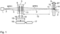
- the device according to the invention as shown in Figure 1 according to a first embodiment, comprises a beam source 1 which emits electromagnetic radiation 2, the beam axis of which is denoted by the reference numeral 3.
- the radiation 2 has a defined power density distribution with a first beam parameter product BPP1.
- the divergent radiation 2 from the beam source 1 enters beam shaping optics 5 as non-collimated radiation.
- the beam-shaping optics 5 serves to variably shape and focus the radiation 2 and has at least one first optical element 6 and at least one second optical element 7.
- the first optical element 6 of this beam-shaping optics 5 is a meniscus lens in the example shown, while the second optical element 7 of the beam-shaping optics 5, which, in the direction of the radiation 2, is positioned behind the first optical element 6, is a biconvex converging lens.
- the first optical element 6 and the second optical element 7 of the beam-shaping optics 5 have spherical surfaces.
- Optical elements 6 or 7 with spherical surfaces have the advantage that they have significantly lower production costs, in contrast to optical elements 6 or 7 which are provided with aspherical surfaces or whose refractive index or shape can be variably changed and adjusted.
- the at least one first optical element 6 generates and / or increases the amount of an aberration
- the at least one second optical element 7 of the beam shaping optics 5 changes the amount generated or increased aberration by changing the position of at least the first optical element 6 or the second optical element 7 is changed so that the radiation 2 emerging from the beam-shaping optics 5, which is focused in the direction of a workpiece 9 to be processed, has a second beam parameter product BPP2.
- the focused radiation 2 emerging from the beam-shaping optics 5 or the second optical element 7 has a beam waist 11.
- a waist distance 12 is defined between the beam waist 11 and a fixed reference plane 13 of the beam shaping optics 5.
- the reference plane 13 is a plane of the beam-shaping optics perpendicular to the beam axis 3, which is suitable for measuring the waist distance 12, and can be defined as desired, but fixed.
- the at least one first optical element 6 of the beam-shaping optics 5 can have the amount of a (in Figure 2 in detail B) generate or increase negative aberration and the at least one second optical element 7 of the beam-shaping optics 5 can then generate or increase the negative aberration in terms of amount by adjusting the setting device 15 by changing the position of at least the first optical element 6 or the second optical Change element 7 so that radiation 2 in a processing zone 10 has the second beam parameter product (BPP2) to be set.
- the beam parameter product (BPP2) adjusted. For example, the distance between the first optical element 6 and the second optical element 7 is increased in order to increase the steel parameter product BPP2 and decreased in order to decrease the beam parameter product PBB2.
- a processing zone 10 is defined as the zone in which the laser material processing (for example cutting, ablation, drilling, scoring, perforating or deep welding) takes place spatially.
- laser material processing for example cutting, ablation, drilling, scoring, perforating or deep welding
- Both the first optical element 6 and the second optical element 7 of the beam-shaping optics 5 can be shifted in the direction of the beam axis 3 via an adjusting device 15 that is controlled via a control module 16, as indicated by a double arrow 19.
- a control module 16 controls the distance between the first optical element 6 and the second optical element 7 and the distance between the first or second optical element 6 or 7 and the beam source 1 .
- the type and extent of the adjustment influence the beam parameter product BPP2, the F number of the focused radiation 2 and its waist distance 12.
- the beam-shaping optics 5 are surrounded by a broken line and vary in size in the various embodiments shown in FIGS Figures 1 to 4 are shown.
- the respective size in the direction of the beam axis 3 indicates in which area the optical elements that are assigned to the beam shaping optics 5, ie at least the first optical element 6 and the second optical element 7, can be shifted in the direction of the beam axis 3, such as this is also indicated by the double arrows 19, which, however, only in Figure 1 are shown.
- the waist distance 12 of the beam waist 11 of the focused radiation 2 to the reference plane 13 of the beam shaping optics 5 is set so that the waist distance of the beam waist 11 of the focused radiation 2 to the reference plane 13 of the beam shaping optics 5 is constant or in the case of a variation of the second beam parameter product BPP2 specified limits varies, as shown below with the aid of the Figure 2 will be explained in more detail.
- the control module 16 can access a stored characteristic curve or a stored characteristic curve field 17.
- a characteristic curve or such a characteristic curve field 17 can be used to access data which indicate the relationship between characteristic values of the focused radiation (BPP2, F number, waist radius (r F )) and the position or the value of an optical property of the elements of the beam-shaping optics and used for setting the second beam parameter product (BPP2) as a function of a required processing result or at least one set or setting process parameter.
- the control module 16 of the setting device 15 can also change the second beam parameter product BPP2 depending on the processing time (time-dependent) and / or depending on the processing position (location-dependent) according to a predetermined characteristic curve or a predetermined family of characteristics 17.
- the position or the optical property of at least one optical element is varied or temporally adjusted according to the required processing result or as a function of a set or set process parameter.
- a location-dependent change in the second beam parameter product BPP2 is to be made if the material processing takes place, for example, on strongly curved paths or a local adaptation of the process parameters, for example through locally varying material properties or varying processing depth are required, while a time-dependent change of the second beam parameter product BPP2 is to be used for those cases in which transient processes such as the heating of the workpiece or the optics are to be taken into account or compensated by ramping the beam properties during machining.
- the second beam parameter product BPP2 can be successively increased by the control module 16 of the setting device 15 as a function of a required machining depth BT in accordance with the predetermined characteristic curve or the predetermined family of characteristics 17 from or above a predetermined machining limit depth BGT with increasing, required machining depth BT.
- the machining limit depth BGT is that predetermined machining depth BT from which a successive change in the beam parameter product BPP2 is made and adapted to the machining depth.
- the beam shaping optics 5 is composed of a first optical element 6 in the form of a meniscus lens and a second optical element 7 in the form of a biconvex lens.
- the small distance between the two optical elements 6 and 7 results in a low-aberration focusing of the exiting radiation 2, so that a beam waist 11 of the focused radiation results below a waist distance 12, which is small, as shown in detail A. .
- the Figure 2 also makes it clear that by means of the beam shaping optics 5 and a different positioning of the first optical element 6 and the second optical element 7, the waist distance 12 of the beam waist 11 of the focused radiation 2 to the fixed reference plane 13, which is assigned to the beam shaping optics 5, within predetermined limits 18, ie within a range indicated by the double arrow in Figure 2 is specified varies.
- the area that is spanned by the specified barriers can be reduced or enlarged.
- the beam parameter product of the radiation directed onto the processing zone can be set variably.
- Figure 2 shows the two extreme positions of the optical components of the beam shaping optics, in which the minimum and maximum beam parameter product BPP2 min and BPP2 max are set.
- the values of BPP min and BPP max are dependent on the embodiment of the beam shaping optics according to the invention, which provides that the second beam parameter product BPP2 min , which is minimally adjustable with the setting device 15, does not fall below the value of the first beam parameter product BPP1 and is preferably identical or only slightly greater than that is the first beam parameter product BPP1, and that the second beam parameter product BPP2 max, which can be set to the maximum with the setting device 15, is at least twice, preferably 5 to 20 times, the second beam parameter product BPP2 min , which can be minimally set with the setting device 15.
- the optical components are designed so that the waist distance 12 of the beam waist 11 of the focused radiation 2 to the fixed reference plane 13 of the beam shaping optics 5 is varied or kept constant with a variation of the second beam parameter product BPP2 within predetermined limits by defining the predetermined limits as a boundary condition in the computational design and optimization of the beam shaping optics.
- the first optical element 6 has a negative focal length, which leads to the radiation being expanded and, in interaction with the positive optical element 7, because of the more easily changeable phase shifts of the wave front of the radiation, aberrations can be generated and changed.
- the control module 16 of the setting device 15 can also use the F-number, that is, the ratio of the distance between the beam waist 11 to the last optical element of the steel shaping optics 5 at the exit of the beam shaping optics 5 and the beam diameter on this element of the focused Radiation 2, can be set on the basis of a predetermined characteristic curve or a predetermined family of characteristics 17.
- the F number of the focused radiation 2 can be set on the basis of the predetermined characteristic curve or the predetermined family of characteristics 17 such that the F number remains constant or is increased with a larger second beam parameter product BPP2.
- the F-number is kept at a constant value while it is decreased in order to increase the beam divergence.
- Figure 3 which shows a third embodiment of the device according to the invention
- the beam-shaping optics 5, in addition to the first optical element 6 and the second optical element 7 on the output side of the second optical element 7, a third optical element 8, the position of which can be changed, which is about the adjusting device 15 can be made.
- the third optical element 8 is a convex-concave lens and is arranged, for example, close to the reference plane 13, while the first and second optical elements 6, 7 are at a small distance from one another, as shown in the illustration above in FIG Figure 3 shows.
- the third optical element 8 of the beam-shaping optics 5 is used to compensate for the change in the waist distance 12 that occurs when the beam parameter product BPP2 is varied by shifting the first and second optical elements 6 and 7, and ideally to keep it constant.
- the arrangement of the optical elements 6, 7 and 8 within the beam-shaping optics 5, as in the upper illustration of FIG Figure 3 is shown, a minimum value of the beam parameter product BPP2 is set.
- the representation of the Figure 3 shows that the beam-shaping optics 5 mean that the waist distance 12 is not only within predetermined limits 18, as is shown on the basis of FIG Figure 2 is explained, is variably adjustable, but can also be kept constant.
- Figure 4 describes an embodiment in which a beam collimation optics 4 is arranged in front of the beam shaping optics 5, so that a collimated beam enters the beam shaping optics.
- the beam shaping optics 5 can according to the examples in FIG Figures 1 to 3 be executed or, as in Figure 4 is shown, be equipped with one or more aspherical lenses.
- the advantage of using aspherical lenses, as in the beam shaping optics 5 of the Figure 4 is shown schematically, consists on the one hand in the fact that a greater range of variation of the beam parameter product BPP2 can be achieved with optical elements with aspherical surfaces in comparison to beam shaping optics with spherical lenses.
- the beam shaping optics can be made more compact because, due to the more efficient phase front deformation caused by the aspherical surfaces, the distances at which the optical components have to be positioned to one another in order to generate the limit values of the beam parameter product are smaller.
- the beam parameter product BPP2, the F number and the radius of the beam waist 11 can be influenced by changing the position of the first and / or the second optical element 6, 7 will be explained below with reference to FIG Figures 5 and 6 described.
- the graphic of the Figure 5 is intended to represent the dependence of the beam parameter product BPP2 and the F number on the position of the first optical element 6, arbitrary units being used for all axes.
- the dependence of the steel parameter product BPP2 on the position of the first optical element 6 is shown by the curve in broken line, while the dependence of the F number on the position of the first optical element 6 is shown by the curve in dotted line.
- the position 0 of the first optical element 6 denotes the minimum adjustable distance to the previous optical element along the optical axis, while the position 1 of the first optical element 6 relates to the maximum adjustable distance from the reference plane 13.
- both the beam parameter product BPP2 and the F number of the beam change.
- the desired values of the beam parameter product BPP2 or the F-number can be set with the aid of the characteristic curve, but these are coupled so that they cannot be set independently of one another simply by changing the position of the first optical element 6.
- Figure 6 now shows a graphic that represents a family of characteristics. Depending on the positions of the first optical element (abscissa) and the second optical element (ordinate), lines of constant waist radii (solid), BPP2's (dashed) and F numbers (dotted) are entered. The direction of growth of the isolines is marked by arrows. In contrast to the embodiment as shown in Figure 5 is shown, the positions of two optical elements are varied here, which means that two of the three variables, for example the beam parameter product BPP2 and the F-number, as far as the adjustability of the beam-shaping optics 5 allows, can be set independently of one another.
- the information and explanations above also apply to item 0 and item 1 Figure 5 .
- a setting trajectory is shown by the dash-dotted line.
- the setting trajectory specifies the manipulated variables for the actuating device, which determine the beam parameter product or the F-number depending on the requirements of the processing task (for example type of processing, processing depth or quality) the process parameters or the processing time, ie time-dependent, and / or depending on the processing position, ie location-dependent, the starting point near 0.1 being represented by a rhombus and the end point near 1.0 being represented by a square.
- the Figure 7 shows three graphs A, B and C, which relate to the power density distribution of the focused radiation in a plane perpendicular to the optical axis at an arbitrary point in the processing zone, for example at the beam waist, with free propagation, without a material.
- the radius r1 is the radius that is defined using the second torque method, while the radius r2 is an auxiliary variable and is assigned to a circle with r> r1 in which almost the entire energy share (at least 90%, preferably between 95% and 100%) is included.
- Graph A shows a beam cross-section of radiation 2 at the position of the beam waist, the grids shown over the beam cross-section being assigned to the corresponding power densities 0 to I max of the power density scale.
- the maximum power density I max is located in the center of the beam cross section, ie in the area of the beam axis 3 in relation to the illustration of FIG Figures 1 to 4 and at the beam radius coordinate 0, while the power density decreases with increasing beam radius coordinate in the direction r1 or r2 (from a dark, dense raster to a light, less dense raster).
- graph B shows the power density distribution as a function of the beam radius coordinate.
- the relation of the two radii r1 and r2 to a power density I (r1) and a power density I (r2) is illustrated.
- the position of the maximum power density I max and the mean power density I mean are shown in graph B.
- the power density distribution of a method according to the invention is characterized, among other things, in that it passes through on planes perpendicular to the optical axis which penetrate or intersect the processing zone 10 when the focused radiation 2 is used, with free propagation, without a material 9 (workpiece) in the beam path a maximum power density I max is defined that is less than 5 times the value, preferably less than 2 to 3 times The value of the mean power density I mean in the respective plane perpendicular to the beam axis on the area enclosed by a circle with the radius r1 defined according to the second moment method.
- the power density distribution of a method according to the invention is further characterized in that it is on planes perpendicular to the optical axis which penetrate or intersect the processing zone 10 when the focused radiation 2 is used, with free propagation, without a material 9 (workpiece) in the beam path, in each case through a defined according to the second moment method defined first radius r1 and each have a second radius r2, with at least 90%, preferably at least 95%, and even more preferably between 99% and 100%, of the laser beam power within a circle with the second radius r2 are included, the second radius r2 being set to a maximum of 1.5 times the value and preferably between 1.1 times and 1.3 times the value of the first radius r1.
- the Figures 8A and 8B show real steel measurements.
- the result of a diagnosis of the laser beam profile is shown when the beam shaping optics 5 are set for BPP min and BPP max .
- the power density distribution of the beam is recorded in several planes along the beam axis 3, defined as the z-axis, in a measurement area around the beam waist 11.
- the jet radius r is determined using the second moment method.
- the beam caustic can be reconstructed by plotting the beam radii along the z-axis. This is on the left side of the figure in the respective graphics of the Figures 8A and 8B shown, for a setting of the beam shaping optics 5 for BPP min ( Figure 8A ) and for BPP max ( Figure 8B ).
- the radius of the beam waist (r F ) is marked separately on the respective beam radius axis.
- Rayleigh length (z R ) is defined as the distance from the beam waist in the direction of propagation in which the beam radius has increased by a factor of 2 1/2 .
- the x and y axes indicate the lateral dimensions of the measuring plane in the x and y directions perpendicular to the z axis (beam axis 3).
- the display scale is determined by the beam waist radius r F.
- the grid scale indicates the normalized power density measured as a function of the position relative to the beam axis 3. Arbitrary units are used for all coordinate axes.
- the arrows that connect the caustic to the power density distributions indicate the associated positions of the measuring planes on the beam axis z.
Landscapes
- Physics & Mathematics (AREA)
- Optics & Photonics (AREA)
- Engineering & Computer Science (AREA)
- General Physics & Mathematics (AREA)
- Plasma & Fusion (AREA)
- Mechanical Engineering (AREA)
- Laser Beam Processing (AREA)
- Lenses (AREA)
Claims (23)
- Dispositif de traitement de matériau avec au moins une source de faisceau (1) de rayonnement électromagnétique qui émet un rayonnement (2) avec une distribution de densité de puissance définie, et une optique de mise en forme de faisceau (5) qui met en forme de manière variable et focalise le rayonnement (2) de la source de faisceau (1), où l'axe optique du rayonnement focalisé (2), appelé axe de faisceau (3), est dirigé sur une zone de traitement (10), et avec des dispositifs qui maintiennent le rayonnement (2) dans le domaine de la surface d'interaction (14) du rayonnement (2) et du matériau (9) qui se forme et se déplace dans la zone de traitement (10), où le rayonnement (2) émis présente un premier produit des paramètres de faisceau (BPP1), c'est-à-dire beam parameter product, et où le rayonnement (2) dans la zone de traitement (10) dans laquelle le rayonnement (2) est en interaction avec le matériau (9), présente un second produit des paramètres de faisceau (BPP2), caractérisé en ce qu'il est prévu un dispositif de réglage (15) qui fait varier le second produit des paramètres de faisceau (BPP2) en modifiant la position ou les propriétés optiques d'au moins un élément optique (6; 7), où au moins un premier élément optique (6) de l'optique de mise en forme de faisceau (5) génère et/ou augmente l'amplitude d'une aberration et au moins un second élément optique (7) de l'optique de mise en forme de faisceau (5) modifie l'aberration générée ou agrandie en termes d'amplitude en ajustant le dispositif de réglage (15) en modifiant la position ou les propriétés optiques d'au moins le premier (6) ou le second élément optique (7) de sorte que le rayonnement (2) présente dans la zone de traitement (10) le second produit des paramètres de faisceau (BPP2) à ajuster.
- Dispositif selon la revendication 1, caractérisé en ce que le au moins un premier élément optique (6) de l'optique de mise en forme de faisceau (5) génère ou augmente l'amplitude d'une aberration négative et le au moins un second élément optique (7) de l'optique de mise en forme de faisceau (5) modifie l'aberration négative générée ou augmentée en termes d'amplitude en ajustant le dispositif de réglage (15) en modifiant la position ou les propriétés optiques d'au moins le premier (6) ou le second élément optique (7) de sorte que le rayonnement (2) présente dans la zone de traitement (10) le second produit des paramètres de faisceau (BPP2) à ajuster.
- Dispositif selon la revendication 1 ou 2, caractérisé en ce que le second produit des paramètres de faisceau qui peut être ajusté au minimum avec le dispositif de réglage (15), (BPP2min), n'est pas situé en dessous de la valeur du premier produit des paramètres de faisceau (BPP1) et est de préférence identique ou seulement légèrement plus grand que le premier produit des paramètres de faisceau (BPP1) et en ce que le second produit de paramètre de faisceau qui peut être ajusté au maximum avec le dispositif de réglage (15), (BPP2max), est au moins deux fois, de préférence 5 à 20 fois, le second produit des paramètres de faisceau qui peut être ajusté au minimum avec le dispositif de réglage (15), (BPP2min).
- Dispositif selon l'une des revendications 1 à 3, caractérisé en ce que l'optique de mise en forme de faisceau (5), vue dans le sens de propagation du rayonnement (2), est disposée du côté sortie d'une optique de collimation de faisceau (4).
- Dispositif selon l'une des revendications 1 à 3, caractérisé en ce que le rayonnement entrant dans l'optique de mise en forme de faisceau (5) avec le premier produit des paramètres de faisceau (BPP1) est un rayonnement non collimaté.
- Dispositif selon l'une des revendications 1 à 5, caractérisé en ce qu'une distance de taille (12) d'une taille de faisceau (11) du rayonnement focalisé (2) à un plan de référence fixe (13) de l'optique de mise en forme de faisceau (5) est constante ou varie dans des limites prédéterminées (18) lors d'une variation du second produit des paramètres de faisceau (BPP2).
- Dispositif selon la revendication 6, caractérisé en ce que lors d'une variation du second produit des paramètres de faisceau (BPP2) avec une distance de taille variable (12) de la taille de faisceau (11) du rayonnement focalisé (2) à un plan de référence fixe (13) de l'optique de mise en forme de faisceau (5) la distance de taille (12) varie ainsi dans des limites prédéterminées (19) par le fait qu'au moins le premier (6) et le second élément optique (7) sont conçus de telle sorte qu'au moins lors d'une modification de la position ou des propriétés optiques d'au moins l'un du premier (6) ou du second élément optique (7), la distance de taille (12) reste dans les limites prédéterminées (18).
- Dispositif selon la revendication 6 ou 7, caractérisé en ce que l'optique de mise en forme de faisceau (5) présente un troisième élément optique (8) qui peut être modifié dans sa position ou ses propriétés optiques, de sorte que la distance de taille (12) peut être ajustée de manière variable ou est constante dans les limites prédéterminées (18).
- Dispositif selon l'une des revendications 1 à 8, caractérisé en ce que le au moins un premier (6) et/ou le au moins un second élément optique (7) de l'optique de mise en forme de faisceau (5) présentent/présente des surfaces sphériques.
- Dispositif selon l'une des revendications 1 à 9, caractérisé en ce que le au moins un premier (6) et/ou le au moins un second élément optique (7) de l'optique de mise en forme de faisceau (5) présentent/présente des surfaces asphériques.
- Dispositif selon l'une des revendications 1 à 10, caractérisé en ce que les propriétés optiques du au moins un premier élément optique (6) et/ou du au moins un second élément optique (7) peuvent être modifiées par une modification de leur/son indice de réfraction, de leur/son gradient d'indice de réfraction ou de leur/sa forme.
- Dispositif selon l'une des revendications 1 à 11, caractérisé en ce que le au moins un premier élément optique (6) et/ou le au moins un second élément optique (7) possèdent/possède une distance focale optique négative.
- Dispositif selon l'une des revendications 1 à 12, caractérisé en ce que le second produit des paramètres de faisceau (BPP2) peut être ajusté par un module de commande (16) du dispositif de réglage (15) en fonction d'un résultat de traitement recherché ou d'au moins un paramètre de processus ajusté ou qui s'ajuste selon une courbe caractéristique prédéterminée ou un champ de courbes caractéristiques prédéterminé (17).
- Dispositif selon la revendication 13, caractérisé en ce que le second produit des paramètres de faisceau (BPP2) peut être modifié par le module de commande (16) du dispositif de réglage (15) en fonction du temps de traitement (en fonction du temps) et/ou en fonction de la position de traitément (en fonction de l'emplacement) selon une courbe caractéristique prédéterminée ou un champ de courbes caractéristiques prédéterminé (17).
- Dispositif selon l'une des revendications 6 à 14, caractérisé en ce que lors d'une modification de la position ou des propriétés optiques d'au moins l'un du premier (6) ou du second élément optique (7) le long d'une courbe caractéristique prédéterminée ou dans un champ de courbes caractéristiques prédéterminé (17) la distance de taille (12) reste dans les limites prédéterminées (18).
- Procédé de traitement de matériau qui utilise au moins une source de faisceau de rayonnement électromagnétique, en particulier une source de faisceau laser (1), où la source de faisceau émet le rayonnement (2), qui présente un premier produit des paramètres de faisceau (BPP1), c'est à dire beam parameter product, avec une distribution de densité de puissance définie et le rayonnement (2) de la source de faisceau (1) est mis en forme de manière variable et focalisé par une optique de mise en forme de faisceau (5), où l'axe optique du rayonnement focalisé (2), appelé axe de faisceau (3), est dirigé sur une zone de traitement (10), et le rayonnement (2) est maintenu dans le domaine de la surface d'interaction (14) du rayonnement (2) et du matériau (9) qui se forme et se déplace dans la zone de traitement (10), où le rayonnement présente dans la zone de traitement (10) dans laquelle le rayonnement (2) interagit avec le matériau (9) un second produit des paramètres de faisceau (BPP2), caractérisé en ce que le second produit de paramètre de faisceau (BPP2) est amené à varier par une modification de la position ou des propriétés optiques d'au moins un élément optique (6; 7), en ce que avec au moins un premier élément optique (6) de l'optique de mise en forme de faisceau (5) l'amplitude d'une aberration est générée ou augmentée et avec au moins un second élément optique (7) de l'optique de mise en forme de faisceau (5) l'aberration générée ou augmentée en termes d'amplitude est modifiée par l'ajustement du dispositif de réglage (15), par le fait que la position ou les propriétés optiques d'au moins le premier (6) ou le second élément optique (7) sont modifiées de sorte que le rayonnement (2) présente dans la zone de traitement (10) le second produit des paramètres de faisceau (BPP2) à ajuster.
- Procédé selon la revendication 16, caractérisé en ce que l'amplitude d'une aberration négative est générée ou augmentée avec le au moins un premier élément optique (6) et en ce que l'aberration négative générée ou augmentée en termes d'amplitude avec le au moins un second élément optique (7) est modifiée par une modification de la position ou des propriétés optiques d'au moins le premier (6) ou second élément optique (7) de sorte que le rayonnement (2) présente dans la zone de traitement (10) le second produit des paramètres de faisceau (BPP2) à ajuster.
- Procédé selon la revendication 16 ou 17, caractérisé en ce que le second produit des paramètres de faisceau (BPP2) est ajusté en fonction d'un résultat de traitement recherché ou d'au moins un paramètre de processus ajusté ou qui s'ajuste selon une courbe caractéristique prédéterminée ou un champ de courbes caractéristiques prédéterminé (17).
- Procédé selon l'une des revendications 16 à 18, caractérisé en ce que des distributions de densité de puissance du rayonnement focalisé (2) dans des plans perpendiculaires à l'axe optique qui pénètrent ou coupent la zone de traitement (10) lors de l'utilisation du rayonnement focalisé (2), sont définies, lors d'une propagation libre, sans matériau (9) (pièce) dans le trajet du faisceau, dans chaque cas par un premier rayon r1 défini selon la méthode du second moment et présentent dans chaque cas un second rayon r2, où au moins 90%, de préférence 95%, et de préférence encore entre 99% et 100%, de la puissance du faisceau laser sont inclus dans un cercle avec le second rayon r2, où le second rayon r2 est ajusté au maximum à 1,5 fois la valeur et de préférence entre 1,1 et 1,3 fois la valeur du premier rayon r1.
- Procédé selon l'une des revendications 16 à 19, caractérisé en ce que des distributions de densité de puissance du rayonnement focalisé (2), dans des plans perpendiculaires à l'axe optique, qui pénètrent ou coupent la zone de traitement (10) lors de l'utilisation du rayonnement focalisé (2), lors d'une propagation libre, sans matériau (9) (pièce) dans le trajet du faisceau, sont définies dans chaque cas par une densité de puissance maximale (Imax) qui est inférieure à 5 fois la valeur, de préférence inférieure à 2 à 3 fois la valeur, de la densité de puissance moyenne (Imean) dans le plan respectif perpendiculaire à l'axe du faisceau sur la surface qui est entourée par un cercle avec le rayon r1 défini selon la méthode du second moment.
- Procédé selon l'une des revendications 16 à 20, caractérisé en ce que le second produit des paramètres de faisceau (BPP2) est augmenté successivement par un module de commande (16) d'un dispositif de réglage (15) en fonction d'une profondeur de traitement recherchée (BT) selon une courbe caractéristique prédéterminée ou un champ de courbes caractéristiques prédéterminé (17) à partir de ou au-dessus d'une profondeur limite de traitement (BGT) prédéterminée avec la profondeur de traitement recherchée (BT) croissante.
- Procédé selon l'une des revendications 16 à 21, caractérisé en ce que lors d'une variation du second produit des paramètres de faisceau (BPP2) également le nombre F (rapport de la distance entre la taille du faisceau (11) et le dernier élément optique à la sortie de l'optique de mise en forme de faisceau et du diamètre du faisceau sur cet élément) du rayonnement focalisé (2) est ajusté par le module de commande (16) du dispositif de réglage (15) à l'aide d'une courbe caractéristique prédéterminée ou d'un champ de courbes caractéristiques prédéterminé (17).
- Procédé selon la revendication 22, caractérisé en ce que le nombre F (valeur de diaphragme) du rayonnement focalisé (2) est ajusté à l'aide de la courbe caractéristique prédéterminée ou du champ de courbes caractéristiques prédéterminé (17) de sorte qu'avec un plus grand second produit des paramètres de faisceau (BPP2) le nombre F reste constant ou est augmenté.
Priority Applications (5)
| Application Number | Priority Date | Filing Date | Title |
|---|---|---|---|
| EP17001479.9A EP3450083B1 (fr) | 2017-09-04 | 2017-09-04 | Dispositif et procédé de traitement de matériau |
| PCT/EP2018/000419 WO2019042581A1 (fr) | 2017-09-04 | 2018-08-30 | Dispositif et procédé d'usinage de matériau |
| US16/648,297 US20200331097A1 (en) | 2017-09-04 | 2018-08-30 | Apparatus and method for material processing |
| CN201880057378.1A CN111278596A (zh) | 2017-09-04 | 2018-08-30 | 用于材料加工的方法和设备 |
| JP2020512820A JP2020532431A (ja) | 2017-09-04 | 2018-08-30 | 材料加工用の装置および方法 |
Applications Claiming Priority (1)
| Application Number | Priority Date | Filing Date | Title |
|---|---|---|---|
| EP17001479.9A EP3450083B1 (fr) | 2017-09-04 | 2017-09-04 | Dispositif et procédé de traitement de matériau |
Publications (2)
| Publication Number | Publication Date |
|---|---|
| EP3450083A1 EP3450083A1 (fr) | 2019-03-06 |
| EP3450083B1 true EP3450083B1 (fr) | 2021-04-14 |
Family
ID=59799180
Family Applications (1)
| Application Number | Title | Priority Date | Filing Date |
|---|---|---|---|
| EP17001479.9A Active EP3450083B1 (fr) | 2017-09-04 | 2017-09-04 | Dispositif et procédé de traitement de matériau |
Country Status (5)
| Country | Link |
|---|---|
| US (1) | US20200331097A1 (fr) |
| EP (1) | EP3450083B1 (fr) |
| JP (1) | JP2020532431A (fr) |
| CN (1) | CN111278596A (fr) |
| WO (1) | WO2019042581A1 (fr) |
Families Citing this family (4)
| Publication number | Priority date | Publication date | Assignee | Title |
|---|---|---|---|---|
| DE102020132688A1 (de) * | 2020-12-08 | 2022-06-09 | Trumpf Laser- Und Systemtechnik Gmbh | System zum Bearbeiten eines Materials mittels ultrakurzer Laserpulse |
| CN113204123B (zh) * | 2021-06-18 | 2025-04-15 | 广东卓劼激光科技有限公司 | 一种多组平行束的激光熔覆光源的整型装置 |
| US20230226640A1 (en) * | 2022-01-20 | 2023-07-20 | Ii-Vi Delaware, Inc. | Laser processing head having wide range zoom |
| US11543098B1 (en) * | 2022-02-01 | 2023-01-03 | Delta Light Nv | Lighting device for the complete and precise projection of a light beam and a method for its use |
Citations (1)
| Publication number | Priority date | Publication date | Assignee | Title |
|---|---|---|---|---|
| US20060044981A1 (en) * | 2004-08-05 | 2006-03-02 | Fanuc Ltd | Laser cutting apparatus |
Family Cites Families (10)
| Publication number | Priority date | Publication date | Assignee | Title |
|---|---|---|---|---|
| GB9501412D0 (en) | 1995-01-25 | 1995-03-15 | Lumonics Ltd | Laser apparatus |
| JP4664269B2 (ja) * | 2006-12-05 | 2011-04-06 | 住友重機械工業株式会社 | レーザ加工装置及びレーザ加工方法 |
| DE102007024700A1 (de) | 2007-05-25 | 2008-12-04 | Fraunhofer-Gesellschaft zur Förderung der angewandten Forschung e.V. | Verfahren zur Materialbearbeitung mit Laserstrahlung sowie Vorrichtung zur Durchführung des Verfahrens |
| FR2935916B1 (fr) | 2008-09-12 | 2011-08-26 | Air Liquide | Procede et installation de coupage laser avec modification du facteur de qualite du faisceau laser |
| US9366887B2 (en) | 2014-02-26 | 2016-06-14 | TeraDiode, Inc. | Systems and methods for laser systems with variable beam parameter product utilizing thermo-optic effects |
| US10401633B2 (en) | 2015-06-23 | 2019-09-03 | TeraDiode, Inc. | Optical element arrangements for varying beam parameter product in laser delivery systems |
| DE102014207624A1 (de) * | 2014-04-23 | 2015-10-29 | Siemens Aktiengesellschaft | Faserlasersystem mit Zoom-Optiksystem zur Materialbearbeitung |
| DE102014116957A1 (de) * | 2014-11-19 | 2016-05-19 | Trumpf Laser- Und Systemtechnik Gmbh | Optisches System zur Strahlformung |
| DE102015101263B4 (de) | 2015-01-28 | 2016-12-15 | Precitec Gmbh & Co. Kg | Vorrichtung zur Materialbearbeitung mittels Laserstrahlung |
| DE102015108248B4 (de) * | 2015-05-26 | 2024-02-08 | Scanlab Gmbh | System für Lasermaterialbearbeitung und Verfahren zum Einstellen der Größe und Position eines Laserfokus |
-
2017
- 2017-09-04 EP EP17001479.9A patent/EP3450083B1/fr active Active
-
2018
- 2018-08-30 JP JP2020512820A patent/JP2020532431A/ja active Pending
- 2018-08-30 WO PCT/EP2018/000419 patent/WO2019042581A1/fr not_active Ceased
- 2018-08-30 US US16/648,297 patent/US20200331097A1/en not_active Abandoned
- 2018-08-30 CN CN201880057378.1A patent/CN111278596A/zh active Pending
Patent Citations (1)
| Publication number | Priority date | Publication date | Assignee | Title |
|---|---|---|---|---|
| US20060044981A1 (en) * | 2004-08-05 | 2006-03-02 | Fanuc Ltd | Laser cutting apparatus |
Also Published As
| Publication number | Publication date |
|---|---|
| EP3450083A1 (fr) | 2019-03-06 |
| CN111278596A (zh) | 2020-06-12 |
| US20200331097A1 (en) | 2020-10-22 |
| JP2020532431A (ja) | 2020-11-12 |
| WO2019042581A1 (fr) | 2019-03-07 |
Similar Documents
| Publication | Publication Date | Title |
|---|---|---|
| EP2778746B1 (fr) | Dispositif optique de formation de faisceaux | |
| EP3221727B1 (fr) | Système de formage par faisceau optique asymétrique | |
| EP3221740B1 (fr) | Système optique de mise en forme d'un faisceau | |
| EP2150372B1 (fr) | Procédé d'enlèvement de matière et dispositif pour réaliser ce procédé | |
| EP4049071B1 (fr) | Élément segmenté de mise en forme de faisceau et installation d'usinage laser | |
| EP2556397B1 (fr) | Méthode et dispositif pour modifier la caractéristique du faisceau optique d'un laser utilisant une fibre multi-gaines | |
| EP3452246B1 (fr) | Optique de reproduction pour l'usinage de matériaux par faisceau laser et tête d'usinage laser équipée de celle-ci | |
| DE102014116958B9 (de) | Optisches System zur Strahlformung eines Laserstrahls, Laserbearbeitungsanlage, Verfahren zur Materialbearbeitung und Verwenden einer gemeinsamen langgezogenen Fokuszone zur Lasermaterialbearbeitung | |
| DE112007001944B4 (de) | Verfahren und Vorrichtung zur Lasermaterialbearbeitung | |
| EP3182191B1 (fr) | Système d'éléments optiques destinés à la mise au point de rayonnements collimatés | |
| DE102016107595B4 (de) | Strahlformungsoptik für Materialbearbeitung mittels eines Laserstrahls sowie Vorrichtung mit derselben | |
| EP3450083B1 (fr) | Dispositif et procédé de traitement de matériau | |
| EP3313607B1 (fr) | Tête de traitement par laser et machine avec une telle tête | |
| EP3860797B1 (fr) | Dispositif pour régler l'emplacement d'un point de focalisation d'un faisceau laser dans un système de traitement au laser, système de traitement au laser comprenant un tel dispositif, et procédé de règlage de l'emplacement d'un point de focalisation d'un faisceau laser dans un système de traitement au laser | |
| EP4196312A1 (fr) | Traitement au laser d'une pièce à travailler ayant une surface incurvée | |
| EP2429755A1 (fr) | Dispositif et procédé permettant l'usinage périphérique au laser d'un cordon de matière | |
| DE102015215645B4 (de) | Vorrichtung und Verfahren zur Erwärmung eines Objekts und Vorrichtung zur Oberflächenbehandlung | |
| DE102018222839A1 (de) | Beleuchtungsanordnung für ein Mikroskop, Mikroskop und Verfahren zur Beleuchtung eines Probenvolumens in einem Mikroskop | |
| DE102008035898A1 (de) | Vorrichtung und Verfahren zur Specklereduktion im Bereich der Laseranwendungen | |
| DE102020121440B4 (de) | Vorrichtung zum Erzeugen einer definierten Laserlinie auf einer Arbeitsebene | |
| DE102022101323A1 (de) | Laserschneideverfahren mit Einstellen der Fokuslage | |
| DE102005017014B4 (de) | Verfahren zur Formung eines Beleuchtungslaserstrahls und Beleuchtungseinrichtung mit einem Laser | |
| DE102021109579A1 (de) | Verfahren und vorrichtung zum ausbilden von modifikationen mit einem laserstrahl in einem material mit einer gekrümmten oberfläche | |
| WO2023247169A1 (fr) | Procédé et dispositif d'usinage de pièces |
Legal Events
| Date | Code | Title | Description |
|---|---|---|---|
| PUAI | Public reference made under article 153(3) epc to a published international application that has entered the european phase |
Free format text: ORIGINAL CODE: 0009012 |
|
| STAA | Information on the status of an ep patent application or granted ep patent |
Free format text: STATUS: THE APPLICATION HAS BEEN PUBLISHED |
|
| AK | Designated contracting states |
Kind code of ref document: A1 Designated state(s): AL AT BE BG CH CY CZ DE DK EE ES FI FR GB GR HR HU IE IS IT LI LT LU LV MC MK MT NL NO PL PT RO RS SE SI SK SM TR |
|
| AX | Request for extension of the european patent |
Extension state: BA ME |
|
| STAA | Information on the status of an ep patent application or granted ep patent |
Free format text: STATUS: REQUEST FOR EXAMINATION WAS MADE |
|
| 17P | Request for examination filed |
Effective date: 20190813 |
|
| RBV | Designated contracting states (corrected) |
Designated state(s): AL AT BE BG CH CY CZ DE DK EE ES FI FR GB GR HR HU IE IS IT LI LT LU LV MC MK MT NL NO PL PT RO RS SE SI SK SM TR |
|
| GRAP | Despatch of communication of intention to grant a patent |
Free format text: ORIGINAL CODE: EPIDOSNIGR1 |
|
| STAA | Information on the status of an ep patent application or granted ep patent |
Free format text: STATUS: GRANT OF PATENT IS INTENDED |
|
| INTG | Intention to grant announced |
Effective date: 20201214 |
|
| GRAS | Grant fee paid |
Free format text: ORIGINAL CODE: EPIDOSNIGR3 |
|
| GRAA | (expected) grant |
Free format text: ORIGINAL CODE: 0009210 |
|
| STAA | Information on the status of an ep patent application or granted ep patent |
Free format text: STATUS: THE PATENT HAS BEEN GRANTED |
|
| AK | Designated contracting states |
Kind code of ref document: B1 Designated state(s): AL AT BE BG CH CY CZ DE DK EE ES FI FR GB GR HR HU IE IS IT LI LT LU LV MC MK MT NL NO PL PT RO RS SE SI SK SM TR |
|
| REG | Reference to a national code |
Ref country code: GB Ref legal event code: FG4D Free format text: NOT ENGLISH |
|
| REG | Reference to a national code |
Ref country code: CH Ref legal event code: EP |
|
| REG | Reference to a national code |
Ref country code: DE Ref legal event code: R096 Ref document number: 502017010046 Country of ref document: DE |
|
| REG | Reference to a national code |
Ref country code: IE Ref legal event code: FG4D Free format text: LANGUAGE OF EP DOCUMENT: GERMAN |
|
| REG | Reference to a national code |
Ref country code: AT Ref legal event code: REF Ref document number: 1381884 Country of ref document: AT Kind code of ref document: T Effective date: 20210515 |
|
| REG | Reference to a national code |
Ref country code: LT Ref legal event code: MG9D |
|
| REG | Reference to a national code |
Ref country code: NL Ref legal event code: MP Effective date: 20210414 |
|
| PG25 | Lapsed in a contracting state [announced via postgrant information from national office to epo] |
Ref country code: NL Free format text: LAPSE BECAUSE OF FAILURE TO SUBMIT A TRANSLATION OF THE DESCRIPTION OR TO PAY THE FEE WITHIN THE PRESCRIBED TIME-LIMIT Effective date: 20210414 Ref country code: HR Free format text: LAPSE BECAUSE OF FAILURE TO SUBMIT A TRANSLATION OF THE DESCRIPTION OR TO PAY THE FEE WITHIN THE PRESCRIBED TIME-LIMIT Effective date: 20210414 Ref country code: BG Free format text: LAPSE BECAUSE OF FAILURE TO SUBMIT A TRANSLATION OF THE DESCRIPTION OR TO PAY THE FEE WITHIN THE PRESCRIBED TIME-LIMIT Effective date: 20210714 Ref country code: FI Free format text: LAPSE BECAUSE OF FAILURE TO SUBMIT A TRANSLATION OF THE DESCRIPTION OR TO PAY THE FEE WITHIN THE PRESCRIBED TIME-LIMIT Effective date: 20210414 Ref country code: LT Free format text: LAPSE BECAUSE OF FAILURE TO SUBMIT A TRANSLATION OF THE DESCRIPTION OR TO PAY THE FEE WITHIN THE PRESCRIBED TIME-LIMIT Effective date: 20210414 |
|
| PG25 | Lapsed in a contracting state [announced via postgrant information from national office to epo] |
Ref country code: LV Free format text: LAPSE BECAUSE OF FAILURE TO SUBMIT A TRANSLATION OF THE DESCRIPTION OR TO PAY THE FEE WITHIN THE PRESCRIBED TIME-LIMIT Effective date: 20210414 Ref country code: IS Free format text: LAPSE BECAUSE OF FAILURE TO SUBMIT A TRANSLATION OF THE DESCRIPTION OR TO PAY THE FEE WITHIN THE PRESCRIBED TIME-LIMIT Effective date: 20210814 Ref country code: GR Free format text: LAPSE BECAUSE OF FAILURE TO SUBMIT A TRANSLATION OF THE DESCRIPTION OR TO PAY THE FEE WITHIN THE PRESCRIBED TIME-LIMIT Effective date: 20210715 Ref country code: PT Free format text: LAPSE BECAUSE OF FAILURE TO SUBMIT A TRANSLATION OF THE DESCRIPTION OR TO PAY THE FEE WITHIN THE PRESCRIBED TIME-LIMIT Effective date: 20210816 Ref country code: PL Free format text: LAPSE BECAUSE OF FAILURE TO SUBMIT A TRANSLATION OF THE DESCRIPTION OR TO PAY THE FEE WITHIN THE PRESCRIBED TIME-LIMIT Effective date: 20210414 Ref country code: NO Free format text: LAPSE BECAUSE OF FAILURE TO SUBMIT A TRANSLATION OF THE DESCRIPTION OR TO PAY THE FEE WITHIN THE PRESCRIBED TIME-LIMIT Effective date: 20210714 Ref country code: RS Free format text: LAPSE BECAUSE OF FAILURE TO SUBMIT A TRANSLATION OF THE DESCRIPTION OR TO PAY THE FEE WITHIN THE PRESCRIBED TIME-LIMIT Effective date: 20210414 Ref country code: SE Free format text: LAPSE BECAUSE OF FAILURE TO SUBMIT A TRANSLATION OF THE DESCRIPTION OR TO PAY THE FEE WITHIN THE PRESCRIBED TIME-LIMIT Effective date: 20210414 |
|
| REG | Reference to a national code |
Ref country code: DE Ref legal event code: R097 Ref document number: 502017010046 Country of ref document: DE |
|
| PG25 | Lapsed in a contracting state [announced via postgrant information from national office to epo] |
Ref country code: CZ Free format text: LAPSE BECAUSE OF FAILURE TO SUBMIT A TRANSLATION OF THE DESCRIPTION OR TO PAY THE FEE WITHIN THE PRESCRIBED TIME-LIMIT Effective date: 20210414 Ref country code: DK Free format text: LAPSE BECAUSE OF FAILURE TO SUBMIT A TRANSLATION OF THE DESCRIPTION OR TO PAY THE FEE WITHIN THE PRESCRIBED TIME-LIMIT Effective date: 20210414 Ref country code: EE Free format text: LAPSE BECAUSE OF FAILURE TO SUBMIT A TRANSLATION OF THE DESCRIPTION OR TO PAY THE FEE WITHIN THE PRESCRIBED TIME-LIMIT Effective date: 20210414 Ref country code: ES Free format text: LAPSE BECAUSE OF FAILURE TO SUBMIT A TRANSLATION OF THE DESCRIPTION OR TO PAY THE FEE WITHIN THE PRESCRIBED TIME-LIMIT Effective date: 20210414 Ref country code: RO Free format text: LAPSE BECAUSE OF FAILURE TO SUBMIT A TRANSLATION OF THE DESCRIPTION OR TO PAY THE FEE WITHIN THE PRESCRIBED TIME-LIMIT Effective date: 20210414 Ref country code: SK Free format text: LAPSE BECAUSE OF FAILURE TO SUBMIT A TRANSLATION OF THE DESCRIPTION OR TO PAY THE FEE WITHIN THE PRESCRIBED TIME-LIMIT Effective date: 20210414 Ref country code: SM Free format text: LAPSE BECAUSE OF FAILURE TO SUBMIT A TRANSLATION OF THE DESCRIPTION OR TO PAY THE FEE WITHIN THE PRESCRIBED TIME-LIMIT Effective date: 20210414 |
|
| PLBE | No opposition filed within time limit |
Free format text: ORIGINAL CODE: 0009261 |
|
| STAA | Information on the status of an ep patent application or granted ep patent |
Free format text: STATUS: NO OPPOSITION FILED WITHIN TIME LIMIT |
|
| 26N | No opposition filed |
Effective date: 20220117 |
|
| REG | Reference to a national code |
Ref country code: BE Ref legal event code: MM Effective date: 20210930 |
|
| GBPC | Gb: european patent ceased through non-payment of renewal fee |
Effective date: 20210904 |
|
| PG25 | Lapsed in a contracting state [announced via postgrant information from national office to epo] |
Ref country code: IS Free format text: LAPSE BECAUSE OF FAILURE TO SUBMIT A TRANSLATION OF THE DESCRIPTION OR TO PAY THE FEE WITHIN THE PRESCRIBED TIME-LIMIT Effective date: 20210814 Ref country code: MC Free format text: LAPSE BECAUSE OF FAILURE TO SUBMIT A TRANSLATION OF THE DESCRIPTION OR TO PAY THE FEE WITHIN THE PRESCRIBED TIME-LIMIT Effective date: 20210414 Ref country code: AL Free format text: LAPSE BECAUSE OF FAILURE TO SUBMIT A TRANSLATION OF THE DESCRIPTION OR TO PAY THE FEE WITHIN THE PRESCRIBED TIME-LIMIT Effective date: 20210414 |
|
| PG25 | Lapsed in a contracting state [announced via postgrant information from national office to epo] |
Ref country code: LU Free format text: LAPSE BECAUSE OF NON-PAYMENT OF DUE FEES Effective date: 20210904 Ref country code: IT Free format text: LAPSE BECAUSE OF FAILURE TO SUBMIT A TRANSLATION OF THE DESCRIPTION OR TO PAY THE FEE WITHIN THE PRESCRIBED TIME-LIMIT Effective date: 20210414 Ref country code: IE Free format text: LAPSE BECAUSE OF NON-PAYMENT OF DUE FEES Effective date: 20210904 Ref country code: GB Free format text: LAPSE BECAUSE OF NON-PAYMENT OF DUE FEES Effective date: 20210904 Ref country code: BE Free format text: LAPSE BECAUSE OF NON-PAYMENT OF DUE FEES Effective date: 20210930 |
|
| P01 | Opt-out of the competence of the unified patent court (upc) registered |
Effective date: 20230524 |
|
| PG25 | Lapsed in a contracting state [announced via postgrant information from national office to epo] |
Ref country code: CY Free format text: LAPSE BECAUSE OF FAILURE TO SUBMIT A TRANSLATION OF THE DESCRIPTION OR TO PAY THE FEE WITHIN THE PRESCRIBED TIME-LIMIT Effective date: 20210414 |
|
| PG25 | Lapsed in a contracting state [announced via postgrant information from national office to epo] |
Ref country code: HU Free format text: LAPSE BECAUSE OF FAILURE TO SUBMIT A TRANSLATION OF THE DESCRIPTION OR TO PAY THE FEE WITHIN THE PRESCRIBED TIME-LIMIT; INVALID AB INITIO Effective date: 20170904 |
|
| REG | Reference to a national code |
Ref country code: AT Ref legal event code: MM01 Ref document number: 1381884 Country of ref document: AT Kind code of ref document: T Effective date: 20220904 |
|
| PG25 | Lapsed in a contracting state [announced via postgrant information from national office to epo] |
Ref country code: AT Free format text: LAPSE BECAUSE OF NON-PAYMENT OF DUE FEES Effective date: 20220904 |
|
| PG25 | Lapsed in a contracting state [announced via postgrant information from national office to epo] |
Ref country code: MK Free format text: LAPSE BECAUSE OF FAILURE TO SUBMIT A TRANSLATION OF THE DESCRIPTION OR TO PAY THE FEE WITHIN THE PRESCRIBED TIME-LIMIT Effective date: 20210414 |
|
| PG25 | Lapsed in a contracting state [announced via postgrant information from national office to epo] |
Ref country code: TR Free format text: LAPSE BECAUSE OF FAILURE TO SUBMIT A TRANSLATION OF THE DESCRIPTION OR TO PAY THE FEE WITHIN THE PRESCRIBED TIME-LIMIT Effective date: 20210414 |
|
| PG25 | Lapsed in a contracting state [announced via postgrant information from national office to epo] |
Ref country code: MT Free format text: LAPSE BECAUSE OF FAILURE TO SUBMIT A TRANSLATION OF THE DESCRIPTION OR TO PAY THE FEE WITHIN THE PRESCRIBED TIME-LIMIT Effective date: 20210414 |
|
| REG | Reference to a national code |
Ref country code: DE Ref legal event code: R082 Ref document number: 502017010046 Country of ref document: DE |
|
| REG | Reference to a national code |
Ref country code: CH Ref legal event code: U11 Free format text: ST27 STATUS EVENT CODE: U-0-0-U10-U11 (AS PROVIDED BY THE NATIONAL OFFICE) Effective date: 20251001 |
|
| PGFP | Annual fee paid to national office [announced via postgrant information from national office to epo] |
Ref country code: DE Payment date: 20250919 Year of fee payment: 9 |
|
| PGFP | Annual fee paid to national office [announced via postgrant information from national office to epo] |
Ref country code: FR Payment date: 20250924 Year of fee payment: 9 |
|
| PGFP | Annual fee paid to national office [announced via postgrant information from national office to epo] |
Ref country code: CH Payment date: 20251001 Year of fee payment: 9 |