EP3450182A1 - Druckmaschine zum direktbedrucken von behältern - Google Patents
Druckmaschine zum direktbedrucken von behältern Download PDFInfo
- Publication number
- EP3450182A1 EP3450182A1 EP18169714.5A EP18169714A EP3450182A1 EP 3450182 A1 EP3450182 A1 EP 3450182A1 EP 18169714 A EP18169714 A EP 18169714A EP 3450182 A1 EP3450182 A1 EP 3450182A1
- Authority
- EP
- European Patent Office
- Prior art keywords
- printing
- printing units
- units
- carousel
- machine according
- Prior art date
- Legal status (The legal status is an assumption and is not a legal conclusion. Google has not performed a legal analysis and makes no representation as to the accuracy of the status listed.)
- Granted
Links
Images


Classifications
-
- B—PERFORMING OPERATIONS; TRANSPORTING
- B41—PRINTING; LINING MACHINES; TYPEWRITERS; STAMPS
- B41M—PRINTING, DUPLICATING, MARKING, OR COPYING PROCESSES; COLOUR PRINTING
- B41M5/00—Duplicating or marking methods; Sheet materials for use therein
- B41M5/0082—Digital printing on bodies of particular shapes
-
- B—PERFORMING OPERATIONS; TRANSPORTING
- B41—PRINTING; LINING MACHINES; TYPEWRITERS; STAMPS
- B41F—PRINTING MACHINES OR PRESSES
- B41F17/00—Printing apparatus or machines of special types or for particular purposes, not otherwise provided for
- B41F17/006—Printing apparatus or machines of special types or for particular purposes, not otherwise provided for for printing on curved surfaces not otherwise provided for
-
- B—PERFORMING OPERATIONS; TRANSPORTING
- B41—PRINTING; LINING MACHINES; TYPEWRITERS; STAMPS
- B41J—TYPEWRITERS; SELECTIVE PRINTING MECHANISMS, i.e. MECHANISMS PRINTING OTHERWISE THAN FROM A FORME; CORRECTION OF TYPOGRAPHICAL ERRORS
- B41J2/00—Typewriters or selective printing mechanisms characterised by the printing or marking process for which they are designed
- B41J2/005—Typewriters or selective printing mechanisms characterised by the printing or marking process for which they are designed characterised by bringing liquid or particles selectively into contact with a printing material
- B41J2/01—Ink jet
- B41J2/135—Nozzles
- B41J2/165—Prevention or detection of nozzle clogging, e.g. cleaning, capping or moistening for nozzles
-
- B—PERFORMING OPERATIONS; TRANSPORTING
- B41—PRINTING; LINING MACHINES; TYPEWRITERS; STAMPS
- B41J—TYPEWRITERS; SELECTIVE PRINTING MECHANISMS, i.e. MECHANISMS PRINTING OTHERWISE THAN FROM A FORME; CORRECTION OF TYPOGRAPHICAL ERRORS
- B41J2/00—Typewriters or selective printing mechanisms characterised by the printing or marking process for which they are designed
- B41J2/005—Typewriters or selective printing mechanisms characterised by the printing or marking process for which they are designed characterised by bringing liquid or particles selectively into contact with a printing material
- B41J2/01—Ink jet
- B41J2/135—Nozzles
- B41J2/165—Prevention or detection of nozzle clogging, e.g. cleaning, capping or moistening for nozzles
- B41J2/16517—Cleaning of print head nozzles
-
- B—PERFORMING OPERATIONS; TRANSPORTING
- B41—PRINTING; LINING MACHINES; TYPEWRITERS; STAMPS
- B41J—TYPEWRITERS; SELECTIVE PRINTING MECHANISMS, i.e. MECHANISMS PRINTING OTHERWISE THAN FROM A FORME; CORRECTION OF TYPOGRAPHICAL ERRORS
- B41J25/00—Actions or mechanisms not otherwise provided for
- B41J25/001—Mechanisms for bodily moving print heads or carriages parallel to the paper surface
-
- B—PERFORMING OPERATIONS; TRANSPORTING
- B41—PRINTING; LINING MACHINES; TYPEWRITERS; STAMPS
- B41J—TYPEWRITERS; SELECTIVE PRINTING MECHANISMS, i.e. MECHANISMS PRINTING OTHERWISE THAN FROM A FORME; CORRECTION OF TYPOGRAPHICAL ERRORS
- B41J25/00—Actions or mechanisms not otherwise provided for
- B41J25/304—Bodily-movable mechanisms for print heads or carriages movable towards or from paper surface
-
- B—PERFORMING OPERATIONS; TRANSPORTING
- B41—PRINTING; LINING MACHINES; TYPEWRITERS; STAMPS
- B41J—TYPEWRITERS; SELECTIVE PRINTING MECHANISMS, i.e. MECHANISMS PRINTING OTHERWISE THAN FROM A FORME; CORRECTION OF TYPOGRAPHICAL ERRORS
- B41J25/00—Actions or mechanisms not otherwise provided for
- B41J25/304—Bodily-movable mechanisms for print heads or carriages movable towards or from paper surface
- B41J25/316—Bodily-movable mechanisms for print heads or carriages movable towards or from paper surface with tilting motion mechanisms relative to paper surface
-
- B—PERFORMING OPERATIONS; TRANSPORTING
- B41—PRINTING; LINING MACHINES; TYPEWRITERS; STAMPS
- B41J—TYPEWRITERS; SELECTIVE PRINTING MECHANISMS, i.e. MECHANISMS PRINTING OTHERWISE THAN FROM A FORME; CORRECTION OF TYPOGRAPHICAL ERRORS
- B41J3/00—Typewriters or selective printing or marking mechanisms characterised by the purpose for which they are constructed
- B41J3/407—Typewriters or selective printing or marking mechanisms characterised by the purpose for which they are constructed for marking on special material
- B41J3/4073—Printing on three-dimensional objects not being in sheet or web form, e.g. spherical or cubic objects
Definitions
- the invention relates to a printing machine for direct printing of containers according to the preamble of claim 1.
- a generic printing machine is from the DE 10 2013 214 980 A1 known. This comprises a carousel for transporting containers and stationary printing units with a plurality of printheads whose distance from the carousel, their vertical position and their inclination with respect to the containers to be printed by means of individually controllable radial modules, height modules and tilting modules can be adjusted.
- the printing units can be individually docked in the periphery of the carousel with the aid of centering means.
- a printing machine used for direct printing of containers and includes: a continuously rotatable carousel for transporting the container; several printing units; and stationary docking stations for peripherally docking the printing units on the carousel.
- the printing machine comprises the docking stations stationarily assigned rail guides for separate movement of the printing units from a docked operating position to the outside to a maintenance position and back again.
- the printing unit is preferably arranged at a distance from the carousel and / or the docking station. The distance facilitates the exchange of individual Modules, functional units, assemblies and / or components, as well as the replacement of complete printing units.
- the printheads In the maintenance position, the printheads, especially including cleaning stations present on the printing units, can be manually and visually inspected.
- Flexible supply lines for example from the central machine area on the carousel, to the printing units can remain connected for maintenance. Consequently, the printing units can also be checked in their maintenance position substantially independent of the operating state of the carousel on functionality.
- the rail guides allow a precise and collision-free guidance of the printing units between the operating position and the maintenance position.
- a distance between docking racks of the printing units and associated docking stations for example, between corresponding end plates of the docking racks and docking stations, preferably at least 0.3 m and in particular at least 0.6 m.
- the rail guides heavy duty full extension, in particular with an extension length of at least 750 mm. This allows a particularly stable and independent of external influences leadership of the printing units on the carousel.
- the printing machine comprises at least one mounting plate / base plate extending radially beyond the carousel and connected to a stationary base frame of the printing press, on which the rail guides are fastened / formed.
- the mounting plate / bottom plate facilitates a precise and reproducible positioning of the individual rail guides with respect to the carousel, and thus also an exact and reproducible positioning of individual printing units on the carousel.
- the printing machine comprises a plurality of identical pitch circle sections, in each of which a docking station with two similar receiving areas for each printing unit and two mutually parallel rail guides are arranged.
- a docking station with two similar receiving areas for each printing unit and two mutually parallel rail guides are arranged.
- the two receiving areas of a docking station are aligned with each other and / or constructed substantially identical.
- the receiving areas and the rail guides are each arranged on both sides and in particular axially symmetrical to a common radial displacement axis for the associated printing units. This facilitates the alignment of the printing units with respect to the respective pitch circle section, in particular in a radial orientation with respect to the carousel.
- the printing units comprise tapered centering pins for pre-centering and clamping pots for locking the printing units on the carousel, the docking stations having corresponding centering holes and clamping bolts.
- the centering pins allow self-guiding pre-centering of the printing units during the approach of the printing units on the rail guides.
- the clamping pots allow after precentring a particularly accurate and reproducible attachment of the printing units in their respective desired position on the carousel.
- the pre-centering in cooperation with the rail guides prevents damage to the clamping heads when approaching the printing units to the carousel.
- the printing units preferably have base frames with uniform mounting points for the rail guides.
- individual pressure units can be flexibly replaced by one another, replaced by other types of pressure units and / or other treatment units.
- the positioning on the mounting points allows economical mounting by means of standardized tools and workflows.
- the printing press further comprises height-adjustable and / or elastically yielding support elements for connecting the printing units to the rail guides.
- height differences between the rail guide and the docking stations can be compensated.
- a positionally true locking is made possible at the docking stations, as remaining height differences and / or inclinations between centering pins and centering holes and / or clamping pots and clamping bolts are compensated by the elastic support elements. Consequently, the clamping pots and clamping bolts work as a particularly accurate self-centering locking.
- the printing units each comprise at least one adjustment unit for the particular separate adjustment of printheads with respect to their vertical and radial position and their inclination towards the carousel.
- the printing units each comprise at least one adjustment unit for the particular separate adjustment of printheads with respect to their vertical and radial position and their inclination towards the carousel.
- an elastically resilient mounting on the rail guides and the self-centering locking at the docking stations thus an equally flexible as accurate and reproducible positioning of individual printheads is possible with respect to the container.
- the printing units include cleaning units with parking heads parked below the print heads and drivable to the print heads cleaning heads.
- the printing units can then be cleaned automatically and thereby visually inspected in the maintenance position, for example when purging the printheads.
- the printing units comprise supply units and suction units for ink, which are arranged on the rear side facing away from the carousel of the printing units.
- the supply units and suction units are then also accessible in the operating position of the printing unit from the outside, for example, after opening an associated machine panel.
- the printing units then do not have to be moved to the maintenance position for the comparatively frequent maintenance of the supply units and suction units.
- the printing units include proximity sensors and the docking stations corresponding and in particular metallic position sensor, for example in the form of sheets.
- the function of the clamping pans can be controlled automatically depending on the established distance between the printing unit and associated recording area.
- the printing press further comprises a machine cover which is subdivided into partial circle sections and which can be selectively opened to extend the printing units in the assigned partial circle section.
- the remote from the printhead part of the printing unit then protrudes, for example, beyond a circumferential line formed by the fully closed machine panel.
- the respectively to be serviced printing units are fully accessible, while the other printing units remain protected from disturbing environmental influences.
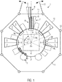
- the printing press 1 comprises a carousel 2 for continuous transport to a container 3 to be printed.
- holders for the containers 3 which are rotatable about themselves are provided in a known manner by means of servomotors or the like. only a few of them are shown).
- the transport of the container on the carousel 2 and the rotation of the container 3 in direct printing are known in principle and therefore not further explained.
- the printing machine 1 further comprises a stationary base frame 4 for the carousel 2 and a plurality of dockable printing units 5, which are preferably constructed identically in their basic function, but may differ, for example, depending on the ink to be processed with respect to circulating or non-circulating ink supplies.
- Additional units such as two printing units 5 together downstream UV curing units for ink, input side and output side inspection units and inlet and outlet stars are in the Fig.1 for purposes of illustration without a separate name indicated by dashed lines.
- the printing units 5 are each mounted on a rail guide 6, with which they can be driven from an inner operating position 7 away from the carousel 2 into an outer maintenance position 8 and back again.
- Fig. 1 is an example of a printing unit 5 in its outer maintenance position 8 and all other printing units 5 in its inner operating position. 7
- the docking stations 9 for the printing units 5 are stationarily associated with the rail guides 6.
- the docking stations 9 preferably comprise a right-hand receiving area 9R (viewed from the printing unit 5) and a left-hand receiving area 9L for each printing unit 5.
- the two receiving areas 9R, 9L are substantially identical constructed and preferably comprise mutually aligned end plates 9a or a common end plate 9a for docking the printing units. 5
- the printing machine 1 is divided into several identical pitch circle sections 10, wherein each two printing units 5 are arranged substantially axially symmetrically with respect to a common displacement axis 10a of the respective pitch circle section 10.
- the displacement axis 10 a is in each case aligned radially with respect to the axis of rotation 2 a of the carousel 2.
- Both rail guides 6 of a specific pitch circle section 10 preferably run parallel to the displacement axis 10a.
- the individual printing units 5 can be moved independently on their rail guides 6 into the outer maintenance position 8. There, the printing units 5 are accessible for maintenance. Depending on the maintenance to be carried out, only one or even both printing stations 5 of a specific pitch circle section 10 can then be moved into the maintenance position 8.
- a mounting plate 11 for the rail guides 6 can be seen and the printing machine 1 laterally delineating protective cover 12.
- the mounting plate 11 forms a machine base and can for example consist of firmly interconnected surface segments.
- the rail guides 6 are preferably bolted to the mounting plate 11 or otherwise fastened for a fixed assignment of the rail guides 6 to the docking stations 9.
- the mounting plate 11 is fixedly connected to the base frame 4 for this purpose.
- the protective covering 12 is preferably segmented by means of fastening columns 13, in particular such that it can be opened separately for individual pitch circle areas 10 in order to allow selective access to the associated printing units 5. This is in the Fig. 1 indicated schematically above.
- the printing units 5 are essentially constructed as per se functional modules.
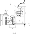
- the printing units 5 comprise adjusting units 14 with a plurality of print heads 15, which can preferably be adjusted both in respect of the carousel 2 radial direction and in its altitude. Furthermore, tilting of the print heads 15 by means of the adjustment unit 14 is also possible. This is indicated by double arrows.
- the adjustment unit 14 is used for independent positioning / adjustment of the individual print heads 15.
- the adjustment unit 14 may comprise mutually exchangeable modules that differ, for example, with respect to the number of print heads 15, with respect to different degrees of freedom of positioning / adjustment and / or associated adjustment paths, with regard to their Adaptability to different pitch circle diameters and / or with regard to different types of pressure heads.
- the printing units 5 furthermore comprise cleaning units 16 with cleaning heads which can be raised to the print heads 15.
- the cleaning units 16 include a number of cleaning heads corresponding to the number of print heads 15 that can be automatically raised from a parking position to clean the print heads 15.
- the printing units 5 also include supply units 17 for ink / ink.
- the supply units 17 are preferably arranged on the rear side facing away from the carousel 2 of the printing units 5 and thus in principle accessible even in the operating position 7 for people.
- the supply units 17 serve in particular both the ink supply of the print heads 15 and the media supply of an associated Drucknebelabsaugung (not shown) and the cleaning units 16, possibly also a decentralized compressed air supply or the like.
- the rear arrangement of the supply units 17 on the printing units 5 allows particularly good access to components, assemblies or the like, for example, for a regular and / or wear-related replacement of ink filters, degassing cartridges of the ink supply or the like.
- Modular subunits, such as a particular ink supply may be changed if another printhead type is to be used or other ink supply requirements change.
- the docking units 19 also comprise end plates 19a with centering pins 20 and clamping jaws 21, which correspond with centering bores 22 and clamping bolts 23 formed on the docking stations 9.
- the base frames 18 are resiliently secured to the movable parts 6a of the rail guides 6.
- the fixed parts 6b of the rail guides 6 are mounted on the mounting plate 11, for example by screwing, clamping or the like.
- the distance DW is defined, for example, between the end plates 9a, 19a of the docking stations 9 and the docking frames 19.
- docking stations 19 and docking stations 9 which are assigned to one another do not touch one another in the maintenance position 8.
- the printing units 5 further include terminal boxes 25 for making electrical connections or the like and supply units 26 for central supply of the printing units 5 with energy, compressed air or the like.
- the terminal boxes 25 are preferably arranged in a lower central position on the printing units 5 in order to keep the cost of the internal wiring and the wiring with the carousel 2, ie towards the base machine as low as possible.
- the supply units 26 are preferably connected centrally via flexible lines 27 or the like in order not to obstruct the movability of the printing units 5 between the operating position 7 and the maintenance position 8.
- the flexible lines 27, such as cables, hoses or the like, are guided for example in drag chains.
- the number of lines 27 between the printing units 5 and the carousel 2 or the basic machine is minimized.
- a power supply and a data connection to the respective printing unit 5 may be sufficient.
- connecting lines can be particularly advantageous for those media / functions that are particularly efficient in the area of the carousel 2 or the basic machine such as central compressed air generation, vacuum generation, suction, ink refilling station or the like.
- the Fig. 3 illustrates embodiments of the Andockgestell 19 for pre-centering formed centering pins 20, which preferably taper at the free end, and the clamping heads 21 for final positioning and locking the printing units 5 at the docking stations 9.
- a proximity sensor 28 is attached to the docking 19, with which monitor the approach of the printing unit 5 to the associated receiving area 9R, 9L.
- the front plate 19a of the docking frame 19 and the base frame 18 with its elastic mounting 24 on the rail guide 6 can also be seen.
- the front plate 19a can be wedge-shaped to align with the corresponding end plate 9a.
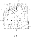
- the Fig. 4 shows embodiments of the corresponding with the centering pins 20 centering holes 22 and the clamping jaws 21 corresponding clamping bolt 23 for two adjacent receiving areas 9R, 9L. Also indicated are the position sensors 29 corresponding to the proximity sensors 28, which are designed, for example, as interrogation plates or the like.
- the centering pins 20 and the associated centering holes 22 are preferably formed in duplicate per printing unit 5 and receiving area 9L, 9R.
- the clamping cups 21 and clamping bolts 22 are preferably formed in a triple version per printing unit 5 and receiving area 9L, 9R. This is on the one hand a sufficiently accurate pre-centering possible, on the other hand, an exact positioning and locking of the printing units 5 both in the horizontal and in the vertical direction.
- the docking frames 19 and the receiving areas 9L, 9R preferably comprise orthogonal to the centering pins 20 and clamping bolts 22 aligned end plates 19a and 9a, which lie flat against each other in the locked state of the printing units 5.
- the receiving areas 9R, 9L preferably share a common end plate 9a. However, this is just as imperative as a mutually aligned arrangement of the receiving areas 9L, 9R.
- the Fig. 5 illustrates the resilient mounting 28 of the base frames 18 of the printing units 5 on the rail guides 6.
- carrier 30 are screwed to the movable parts 6a of the rail guide 6.
- the elastic support 24 is seated in particular in the form of elastically yielding support elements 24a for the base frames 18. This allows an immovable connection between the printing units 5 and the movable parts 6a of the rail guides 6, for example, when moving to the maintenance position 8. At the same time compensatory mobility of the printing units 5 with respect to the rail guides 6 when docking in the operating position 7 allows.
- clamping heads 21 and clamping bolt 23 can cooperate substantially without external tension and lock the printing units 5 accurately and reproducibly at the docking stations 9.
- the elastically yielding support elements 24a are formed, for example, as a rubber-metal buffer.
- the rubber-metal bumpers are then fastened to the carriers 30, for example, by means of countered threaded bolts in order to be able to adjust the vertical position of the printing units 5 on each support element 24a separately relative to the respective rail guide 6.
- the height position of the centering bolts 20 for pre-centering can be adapted to the associated centering bores 22.
- Height-adjustable support elements 24a allow a particularly gentle pre-centering and subsequent positioning of the clamping heads 21 on the clamping bolt 23.
- the clamping cups 21 thus remain protected when starting the operating position 7 from damage and still allow a reproducible and accurate mounting and locking of the printing units 5 at their respective receiving area 9R , 9L.
- the rail guides 6 are preferably designed as heavy duty full extension, for example, with an extension length of at least 750 mm.
- the full extension may comprise stop dampers 31 for vibration-free positioning.
- the rail guides 6 could also be designed in such a way that the printing units 5 can be completely moved out of the area of the printing machine 1 and separated from it.
- the rail guides 6 would not be designed as heavy-duty pullouts but, for example, as open guide rails, in / on which drive the printing units 5 on wheels.
- the full extenders described are advantageous in terms of the significantly lower adjustment effort for the print heads 15, that is, in terms of the better reproducible positioning in the operating position 7.
- the printing units 5 can in principle be docked in any arrangement and order on the printing machine 1.
- the base frames 18 of all printing units 5 preferably comprise for this purpose identical mounting points matching the support elements 24a on the rail guides 6.
- the printing units 5 can be preassembled there independently of the basic machine / carousel 2, put into operation and / or tested, for example with connection to a simulator for simulating the basic machine. Efficient waiting / overhauling of the printing units 5 is also possible under these conditions.
- Identical printing units 5 can be used on different sized subcircuits / basic machines. Printing presses 1 can only be partially equipped with printing units 5. Likewise, it is possible in principle to expand the functional scope of the printing press 1 successively by equipping an increasing number of partial circle sections 10 and / or receiving areas 9R, 9L with printing units 5.
- the printing units 5 are preferably constructed and controlled such that their functions can be tested independently of the carousel 2 or the printing machine 1.
- the printing units 5 can be connected, for example, to a suitable machine simulator.
- a suitable machine simulator For the commissioning of the tested printing units 5 on the printing machine 1 then only the central connection by means of the flexible lines 26 and an initial printhead adjustment would be necessary.
Landscapes
- Engineering & Computer Science (AREA)
- Manufacturing & Machinery (AREA)
- Ink Jet (AREA)
- Rotary Presses (AREA)
Abstract
Description
- Die Erfindung betrifft eine Druckmaschine zum Direktbedrucken von Behältern gemäß dem Oberbegriff des Anspruchs 1.
- Eine gattungsgemäße Druckmaschine ist aus der
DE 10 2013 214 980 A1 bekannt. Diese umfasst ein Karussell zum Transportieren von Behältern und stationäre Druckeinheiten mit mehreren Druckköpfen, deren Abstand vom Karussell, deren vertikale Position und deren Neigung bezüglich der zu bedruckenden Behälter mittels einzeln steuerbarer Radialmodule, Höhenmodule und Kippmodule eingestellt werden kann. Die Druckeinheiten können einzeln in der Peripherie des Karussells unter Zuhilfenahme von Zentriermitteln angedockt werden. - Obwohl dies eine flexible Ausrichtung der Druckköpfe und ermöglicht und die Druckeinheiten sowohl vorübergehend vom Karussell gelöst als auch dauerhaft ausgetauscht werden können, ist eine umfassende Funktionskontrolle der Druckeinheiten und/oder eine Wartung der Druckeinheiten in der Regel nur bei angedockter Druckeinheit am betriebsbereiten Karussell, also bei voll funktionstüchtiger Druckmaschine, möglich. Unter dieser Voraussetzung ist der Zugang zu einzelnen Baugruppen für die Montage und/oder Wartung jedoch stark eingeschränkt. Auch sind die einzelnen Druckköpfe dann während ihrer Reinigung nur schwer erreichbar, so dass einzelne Reinigungsschritte nicht visuell kontrolliert werden können. Außerdem besteht zunehmend Bedarf für ein flexibles und schnelles Andocken der Druckaggregate oder anderweitiger Behandlungsaggregate in unterschiedlichen Teilkreisabschnitten.
- Es wäre somit wünschenswert, wenigstens eines der oben genannten Probleme abzumildern oder gar zu beseitigen, ohne dadurch die Positionierungsgenauigkeit einzelner Druckköpfe bezüglich des Karussells einzuschränken.
- Die gestellte Aufgabe wird mit einer Druckmaschine gemäß Anspruch 1 gelöst. Demnach dient diese zum Direktbedrucken von Behältern und umfasst: ein kontinuierlich drehbares Karussell zum Transport der Behälter; mehrere Druckaggregate; und stationäre Andockstationen zum peripheren Andocken der Druckaggregate am Karussell. Erfindungsgemäß umfasst die Druckmaschine den Andockstationen ortsfest zugeordnete Schienenführungen zum separaten Verfahren der Druckaggregate von einer angedockten Betriebsposition nach außen hin bis in eine Wartungsposition und wieder zurück.
- In der Wartungsposition ist das Druckaggregat vorzugsweise im Abstand zum Karussell und/oder der Andockstation angeordnet. Der Abstand erleichtert den Austausch einzelner Module, funktionaler Einheiten, Baugruppen und/oder Bauteile, ebenso den Austausch kompletter Druckaggregate.
- In der Wartungsposition können die Druckköpfe, insbesondere einschließlich an den Druckaggregaten vorhandener Reinigungsstationen, manuell und visuell kontrolliert werden. Flexible Versorgungsleitungen, beispielsweise vom zentralen Maschinenbereich am Karussell, zu den Druckaggregaten können für Wartungsarbeiten angeschlossen bleiben. Folglich können die Druckaggregate auch in ihrer Wartungsposition im Wesentlichen unabhängig vom Betriebszustand des Karussells auf Funktionstüchtigkeit überprüft werden können.
- Die Schienenführungen ermöglichen eine präzise und kollisionsfreie Führung der Druckaggregate zwischen der Betriebsposition und der Wartungsposition.
- Unter einer ortsfesten Zuordnung der Schienenführungen ist eine bezüglich des Karussells festgelegte Montageposition der Schienenführungen zu verstehen. Beispielsweise durch eine Verschraubung, durch einen Formschluss der Schienenführungen bezüglich eines Grundgestells des Karussells oder dergleichen.
- In der Wartungsposition beträgt ein Abstand zwischen Andockgestellen der Druckaggregate und zugeordneten Andockstationen, beispielsweise zwischen korrespondierenden Stirnplatten der Andockgestelle und Andockstationen, vorzugsweise wenigstens 0,3 m und insbesondere wenigstens 0,6 m.
- Vorzugsweise sind die Schienenführungen Schwerlast-Vollauszüge, insbesondere mit einer Auszugslänge von wenigstens 750 mm. Dies ermöglicht eine besonders stabile und von äußeren Einflüssen unabhängige Führung der Druckaggregate am Karussell.
- Vorzugsweise umfasst die Druckmaschine wenigstens eine radial über das Karussell hinausreichende und mit einem stationären Grundgestell der Druckmaschine verbundene Montageplatte / Bodenplatte, auf/in der die Schienenführungen befestigt/ausgebildet sind. Die Montageplatte / Bodenplatte erleichtert eine präzise und reproduzierbare Positionierung der einzelnen Schienenführungen bezüglich des Karussells, und somit auch eine exakte und reproduzierbare Positionierung einzelner Druckaggregate am Karussell.
- Vorzugsweise umfasst die Druckmaschine mehrere identische Teilkreisabschnitte, in denen jeweils eine Andockstation mit zwei gleichartigen Aufnahmebereichen für je ein Druckaggregat und zwei zueinander parallele Schienenführungen angeordnet sind. Dies ermöglicht eine besonders platzsparende Anordnung von jeweils zwei Druckaggregaten nebeneinander bei gleichzeitig guter Zugänglichkeit der einzelnen funktionalen Einheiten, Baugruppen und/oder Bauteile in der Wartungsposition der einzelnen Druckaggregate.
- Vorzugsweise sind die beiden Aufnahmebereiche einer Andockstation zueinander fluchtend angeordnet und/oder im Wesentlichen identisch aufgebaut.
- Vorzugsweise sind die Aufnahmebereiche und die Schienenführungen jeweils beidseitig und insbesondere achsensymmetrisch zu einer gemeinsamen radialen Verschiebeachse für die zugeordneten Druckaggregate angeordnet. Dies erleichtert die Ausrichtung der Druckaggregate bezüglich des jeweiligen Teilkreisabschnitts insbesondere in einer radialen Ausrichtung bezüglich des Karussells.
- Vorzugsweise umfassen die Druckaggregate konisch zulaufende Zentrierbolzen zur Vorzentrierung und Spanntöpfe zur Verriegelung der Druckaggregate am Karussell, wobei die Andockstationen damit korrespondierende Zentrierbohrungen und Spannbolzen aufweisen.
- Die Zentrierbolzen ermöglichen eine selbstführende Vorzentrierung der Druckaggregate während des Heranfahrens der Druckaggregate auf den Schienenführungen. Die Spanntöpfe ermöglichen nach erfolgter Vorzentrierung eine besonders exakte und reproduzierbare Befestigung der Druckaggregate in ihrer jeweiligen Sollposition am Karussell. Zudem verhindert die Vorzentrierung im Zusammenwirken mit den Schienenführungen eine Beschädigung der Spanntöpfe beim Heranfahren der Druckaggregate an das Karussell.
- Vorzugsweise weisen die Druckaggregate Grundgestelle mit einheitlichen Montagepunkten für die Schienenführungen auf. Dadurch lassen sich einzelne Druckaggregate flexibel gegenseitig austauschen, durch andere Druckaggregattypen und/oder anderweitige Behandlungsaggregate ersetzen. Die Positionierung auf den Montagepunkten ermöglicht eine wirtschaftliche Befestigung mittels standardisierter Hilfsmittel und Arbeitsabläufe.
- Vorzugsweise umfasst die Druckmaschine ferner höhenverstellbare und/oder elastisch nachgiebige Auflageelemente zum Verbinden der Druckaggregate mit den Schienenführungen. Dadurch lassen sich zum Einen Höhendifferenzen zwischen der Schienenführung und den Andockstationen ausgleichen. Zum Anderen wird eine positionsgetreue Verriegelung an den Andockstationen ermöglicht, da verbleibende Höhendifferenzen und/oder Schrägstellungen zwischen Zentrierbolzen und Zentrierbohrungen und/oder Spanntöpfen und Spannbolzen von den elastischen Auflageelementen ausgeglichen werden. Folglich arbeiten die Spanntöpfe und Spannbolzen als besonders exakt selbstzentrierende Verriegelung.
- Vorzugsweise umfassen die Druckaggregate jeweils wenigstens eine Verstelleinheit zum insbesondere separaten Verstellen von Druckköpfen bezüglich ihrer vertikalen und radialen Position sowie ihrer Neigung zum Karussell hin. Insbesondere in Kombination mit einer elastisch nachgiebigen Lagerung auf den Schienenführungen und der selbstzentrierenden Verriegelung an den Andockstationen ist somit eine gleichermaßen flexible wie exakte und reproduzierbare Positionierung einzelner Druckköpfe bezüglich der Behälter möglich.
- Vorzugsweise umfassen die Druckaggregate Reinigungseinheiten mit unterhalb der Druckköpfe geparkten und zu den Druckköpfen fahrbaren Reinigungsköpfen. Die Druckaggregate können dann automatisch gereinigt und dabei in der Wartungsposition visuell kontrolliert werden, beispielsweise beim Purgen der Druckköpfe.
- Vorzugsweise umfassen die Druckaggregate Versorgungseinheiten und Absaugeinheiten für Tinte, die an der vom Karussell abgewandten Rückseite der Druckaggregate angeordnet sind. Die Versorgungseinheiten und Absaugeinheiten sind dann auch in der Betriebsposition des Druckaggregats von außen her zugänglich, beispielsweise nach Öffnen einer zugehörigen Maschinenverkleidung. Die Druckaggregate müssen dann für die vergleichsweise häufige Wartung der Versorgungseinheiten und Absaugeinheiten nicht in die Wartungsposition gefahren werden.
- Vorzugsweise umfassen die Druckaggregate Näherungssensoren und die Andockstationen damit korrespondierende und insbesondere metallische Positionsgeber, beispielsweise in Form von Blechen. Damit lässt sich die Funktion der Spanntöpfe in Abhängigkeit vom festgestellten Abstand zwischen Druckaggregat und zugeordnetem Aufnahmebereich automatisch steuern.
- Vorzugsweise umfasst die Druckmaschine ferner eine in Teilkreisabschnitte gegliederte Maschinenverkleidung, die sich zum Ausfahren der Druckaggregate selektiv im zugeordneten Teilkreisabschnitt öffnen lässt. Der von den Druckköpfen abgewandte Teil des Druckaggregats ragt dann beispielsweise über eine von der vollständig geschlossenen Maschinenverkleidung gebildeten Umfangslinie hinaus. Somit sind die jeweils zu wartenden Druckaggregate uneingeschränkt zugänglich, während die übrigen Druckaggregate vor störenden Umgebungseinflüssen geschützt bleiben.
- Eine bevorzugte Ausführungsform der Erfindung ist zeichnerisch dargestellt. Es zeigen:
- Fig. 1
- eine schematische Draufsicht auf die Druckmaschine;
- Fig. 2
- ein Druckaggregat in einer schematischen seitlichen Ansicht;
- Fig. 3
- eine Schrägansicht eines an den Druckaggregaten ausgebildeten Andockgestells;
- Fig. 4
- eine Schrägansicht am Karussell ausgebildeter Aufnahmebereiche für je eine Andockeinheit; und
- Fig. 5
- eine bevorzugte Ausführungsform der Schienenführung.
- Wie die
Fig. 1 in schematischer Darstellung erkennen lässt, umfasst die Druckmaschine 1 in einer bevorzugten Ausführungsform ein Karussell 2 zum kontinuierlichen Transport zu bedruckender Behälter 3. An dem Karussell 2 sind auf bekannte Weise mittels Servomotoren oder dergleichen um sich selbst drehbare Halterungen für die Behälter 3 umfänglich gleichmäßig verteilt (jeweils nur einige davon dargestellt). Der Transport der Behälter auf dem Karussell 2 sowie die Drehung der Behälter 3 beim Direktbedrucken sind prinzipiell bekannt und daher nicht weiter erläutert. - Die Druckmaschine 1 umfasst ferner ein stationäres Grundgestell 4 für das Karussell 2 und mehrere andockbare Druckaggregate 5, die bezüglich ihrer Grundfunktion vorzugsweise identisch aufgebaut sind, sich aber beispielsweise je nach zu verarbeitender Druckfarbe bezüglich zirkulierender oder nicht-zirkulierender Tintenversorgungen unterscheiden können.
- Zusätzliche Aggregate, wie beispielsweise jeweils zwei Druckaggregaten 5 gemeinsam nachgeordnete UV-Anhärtungseinheiten für Druckfarbe, eingangsseitige und ausgangsseitige Inspektionseinheiten sowie Einlauf- und Auslaufsterne sind in der
Fig.1 zur Veranschaulichung ohne separate Bezeichnung gestrichelt angedeutet. - Die Druckaggregate 5 sind jeweils auf einer Schienenführung 6 gelagert, mit der sie von einer inneren Betriebsposition 7 vom Karussell 2 weg bis in eine äußere Wartungsposition 8 und wieder zurück gefahren werden können. In der
Fig. 1 befindet beispielhaft ein Druckaggregat 5 in seiner äußeren Wartungsposition 8 und alle anderen Druckaggregate 5 in ihrer inneren Betriebsposition 7. - Den Schienenführungen 6 ortsfest zugeordnet sind stationäre Andockstationen 9 für die Druckaggregate 5. Die Andockstationen 9 umfassen vorzugsweise einen (vom Druckaggregat 5 aus gesehen) rechten Aufnahmebereich 9R und einen linken Aufnahmebereich 9L für je ein Druckaggregat 5. Die beiden Aufnahmebereiche 9R, 9L sind im Wesentlichen identisch aufgebaut und umfassen vorzugsweise miteinander fluchtende Stirnplatten 9a oder eine gemeinsame Stirnplatte 9a zum Andocken der Druckaggregate 5.
- Wie die
Fig. 1 ferner erkennen lässt, ist die Druckmaschine 1 in mehrere identische Teilkreisabschnitte 10 gegliedert, wobei jeweils zwei Druckaggregate 5 bezüglich einer gemeinsamen Verschiebeachse 10a des jeweiligen Teilkreisabschnitts 10 im Wesentlichen achsensymmetrisch angeordnet sind. Die Verschiebeachse 10a ist jeweils radial bezüglich der Drehachse 2a des Karussells 2 ausgerichtet. Beide Schienenführungen 6 eines bestimmten Teilkreisabschnitts 10 verlaufen vorzugsweise parallel zur Verschiebeachse 10a. - Die einzelnen Druckaggregate 5 lassen sich auf ihren Schienenführungen 6 vorzugsweise unabhängig voneinander bis in die äußere Wartungsposition 8 fahren. Dort sind die Druckaggregate 5 für Wartungsarbeiten zugänglich. Je nach auszuführender Wartung kann dann nur eine oder auch beide Druckstationen 5 eines bestimmten Teilkreisabschnitts 10 in die Wartungsposition 8 gefahren werden.
- In der
Fig. 1 sind ferner eine Montageplatte 11 für die Schienenführungen 6 zu erkennen sowie eine die Druckmaschine 1 seitlich begrenzende Schutzverkleidung 12. Die Montageplatte 11 bildet einen Maschinenboden aus und kann beispielsweise aus fest miteinander verbundenen Flächensegmenten bestehen. - Die Schienenführungen 6 sind vorzugsweise auf der Montageplatte 11 verschraubt oder anderweitig befestig für eine ortsfeste Zuordnung der Schienenführungen 6 zu den Andockstationen 9. Die Montageplatte 11 ist zu diesem Zweck fest mit dem Grundgestell 4 verbunden.
- Die Schutzverkleidung 12 ist vorzugsweise mittels Befestigungssäulen 13 segmentiert, insbesondere so, dass sie sich für einzelne Teilkreisbereiche 10 separat öffnen lässt, um einen selektiven Zugang zu den zugeordneten Druckaggregaten 5 zu ermöglichen. Dies ist in der
Fig. 1 oben schematisch angedeutet. - Wie die
Fig. 2 in schematischer Darstellung erkennen lässt, sind die Druckaggregate 5 im Wesentlichen als für sich genommen funktionstüchtige Module aufgebaut. Zu diesem Zweck umfassen die Druckaggregate 5 Verstelleinheiten 14 mit mehreren Druckköpfen 15, die sich vorzugsweise sowohl in bezüglich des Karussells 2 radialer Richtung als auch in ihrer Höhenlage verstellen lassen. Vorzugsweise ist ferner ein Neigen der Druckköpfe 15 mittels der Verstelleinheit 14 möglich. Dies ist durch Doppelpfeile angedeutet. - Insbesondere dient die Verstelleinheit 14 zur unabhängigen Positionierung/Justierung der einzelnen Druckköpfe 15. Die Verstelleinheit 14 kann gegenseitig austauschbare Module umfassen, die sich beispielsweise hinsichtlich der Anzahl der Druckköpfe 15 unterscheiden, hinsichtlich unterschiedlicher Freiheitsgrade der Positionierung/Justierung und/oder zugehöriger Verstellwege, hinsichtlich ihrer Anpassbarkeit an unterschiedliche Teilkreisdurchmesser und/oder hinsichtlich unterschiedlicher Druckkopftypen.
- Die Druckaggregate 5 umfassen ferner Reinigungseinheiten 16 mit zu den Druckköpfen 15 hochfahrbaren Reinigungsköpfen. Vorzugsweise umfassen die Reinigungseinheiten 16 eine der Anzahl der Druckköpfe 15 entsprechende Anzahl von Reinigungsköpfen, die sich aus einer Parkposition automatisch zur Reinigung der Druckköpfe 15 anheben lassen.
- Die Druckaggregate 5 umfassen zudem Versorgungseinheiten 17 für Druckfarbe / Tinte. Die Versorgungseinheiten 17 sind vorzugsweise auf der vom Karussell 2 abgewandten Rückseite der Druckaggregate 5 angeordnet und somit prinzipiell auch in der Betriebsposition 7 für Personen zugänglich.
- Die Versorgungseinheiten 17 dienen insbesondere sowohl der Tintenversorgung der Druckköpfe 15 als auch der Medienversorgung einer zugehörigen Drucknebelabsaugung (nicht dargestellt) und der Reinigungseinheiten 16, gegebenenfalls auch einer dezentralen Druckluftversorgung oder dergleichen. Die rückseitige Anordnung der Versorgungseinheiten 17 an den Druckaggregaten 5 ermöglicht einen besonders guten Zugang zu Bauteilen, Baugruppen oder dergleichen, beispielsweise für einen regelmäßigen und/oder verschleißbedingten Ersatz von Tintenfiltern, Entgasungspatronen der Tintenversorgung oder dergleichen. Modulare Untereinheiten, wie beispielsweise eine bestimmte Tintenversorgung, können gewechselt werden, falls ein anderer Druckkopftyp eingesetzt werden soll oder sich anderweitige Anforderungen an die Tintenversorgung ändern.
- Die Druckaggregate 5 umfassen ferner Grundgestelle 18 und fest damit verbundene Andockgestelle 19 zum Andocken an den Andockstationen 9. Die Andockgestelle 19 umfassen Stirnplatten 19a mit Zentrierbolzen 20 und Spanntöpfen 21, die mit an den Andockstationen 9 ausgebildeten Zentrierbohrungen 22 und Spannbolzen 23 korrespondieren.
- Die Grundgestelle 18 sind elastisch nachgiebig auf den beweglichen Teilen 6a der Schienenführungen 6 befestigt. Die feststehenden Teile 6b der Schienenführungen 6 sind auf der Montageplatte 11 befestigt, beispielsweise durch Verschrauben, Klemmen oder dergleichen.
- Aufgrund der nachgiebigen Lagerung 24 der Grundgestelle 18 können die Andockgestelle 19 und Andockstationen 9 mittels der Zentrierbolzen 20 und Zentrierbohrungen 22 selbstzentrierend aneinander gefahren und dann spannungsarm mittels der Spanntöpfe 21 und Spannbolzen 23 miteinander verriegelt werden. Verbleiben trotz einer Höhenjustierung der Druckaggregate 5 Positionierungsungenauigkeiten zwischen den Andockgestellen 19 und Andockstationen 9, so werden diese Ungenauigkeiten von der nachgiebigen Lagerung 24 der Grundgestelle 18 ausgeglichen und die Spanntöpfe 21 und Spannbolzen 23 davon entlastet.
- Dies ermöglicht eine sehr exakte und reproduzierbare Positionierung der Druckaggregate 5 und ihrer Druckköpfe 15 bezüglich des Karussells 2. Somit bilden die Andockgestelle 19 mit den zugehörigen Andockstationen 9 jeweils separate Nullpunktspannsysteme aus.
- Der Übersichtlichkeit halber ist das Druckaggregat 5 in der
Fig. 2 in seiner Wartungsposition 8 dargestellt, also in einem geeigneten radialen Abstand DW vom Karussell 2. Der Abstand DW ist beispielsweise zwischen den Stirnplatten 9a, 19a der Andockstationen 9 und der Andockgestelle 19 definiert. Im Gegensatz zur Betriebsposition 7 berühren sich einander zugeordnete Andockgestelle 19 und Andockstationen 9 in der Wartungsposition 8 nicht. - Die Druckaggregate 5 umfassen ferner Klemmkästen 25 zum Herstellen elektrischer Verbindungen oder dergleichen sowie Versorgungseinheiten 26 zur zentralen Versorgung der Druckaggregate 5 mit Energie, Druckluft oder dergleichen.
- Die Klemmkästen 25 sind vorzugsweise in einer unteren zentralen Position an den Druckaggregaten 5 angeordnet, um den Aufwand für die interne Verkabelung und die Verkabelung mit dem Karussell 2, also zur Grundmaschine hin, möglichst gering zu halten.
- Die Versorgungseinheiten 26 sind vorzugsweise über flexible Leitungen 27 oder dergleichen zentral angeschlossen, um die Verfahrbarkeit der Druckaggregate 5 zwischen Betriebsposition 7 und Wartungsposition 8 nicht zu behindern. Die flexiblen Leitungen 27, wie beispielsweise Kabel, Schläuche oder dergleichen, werden beispielsweise in Schleppketten geführt.
- Vorzugweise wird die Anzahl der Leitungen 27 zwischen den Druckaggregaten 5 und dem Karussell 2 bzw. der Grundmaschine minimiert. Beispielsweise können eine Stromversorgung und eine Datenverbindung zum jeweiligen Druckaggregat 5 ausreichend sein. Zusätzlich können Verbindungsleitungen insbesondere für solche Medien/Funktionen vorteilhaft sein, die sich besonders effizient im Bereich des Karussells 2 bzw. der Grundmaschine vorhalten lassen, wie beispielsweise eine zentrale Drucklufterzeugung, Vakuumerzeugung, Absaugung, Tintennachfüllstation oder dergleichen.
- Die
Fig. 3 verdeutlicht Ausführungsformen der am Andockgestell 19 zur Vorzentrierung ausgebildeten Zentrierbolzen 20, die vorzugsweise am freien Ende konisch zulaufen, sowie der Spanntöpfe 21 zur endgültigen Positionierung und Verriegelung der Druckaggregate 5 an den Andockstationen 9. Vorzugsweise ist am Andockgestell 19 ein Näherungssensor 28 befestigt, mit dem sich die Annäherung des Druckaggregats 5 an den zugeordneten Aufnahmebereich 9R, 9L überwachen lässt. Zu erkennen ist ferner die Stirnplatte 19a des Andockgestells 19 sowie das Grundgestell 18 mit dessen elastischer Lagerung 24 auf der Schienenführung 6. Die Stirnplatte 19a kann zur Ausrichtung passend zur korrespondierenden Stirnplatte 9a keilförmig ausgebildet sein. - Die
Fig. 4 zeigt Ausführungsformen der mit den Zentrierbolzen 20 korrespondierenden Zentrierbohrungen 22 und der mit den Spanntöpfen 21 korrespondierende Spannbolzen 23 für zwei benachbarte Aufnahmebereiche 9R, 9L. Angedeutet sind ferner mit den Näherungssensoren 28 korrespondierende Positionsgeber 29, die beispielsweise als Abfragebleche oder dergleichen ausgebildet sind. - Die Zentrierbolzen 20 und die zugehörigen Zentrierbohrungen 22 sind vorzugsweise in zweifacher Ausführung pro Druckaggregat 5 und Aufnahmebereich 9L, 9R ausgebildet. Die Spanntöpfe 21 und Spannbolzen 22 sind vorzugsweise in dreifacher Ausführung pro Druckaggregat 5 und Aufnahmebereich 9L, 9R ausgebildet. Damit ist zum einen eine ausreichend genaue Vorzentrierung möglich, zum anderen eine exakte Positionierung und Verriegelung der Druckaggregate 5 sowohl in horizontaler als auch in vertikaler Richtung.
- Zu diesem Zweck umfassen die Andockgestelle 19 und die Aufnahmebereiche 9L, 9R vorzugsweise orthogonal zu den Zentrierbolzen 20 und Spannbolzen 22 ausgerichtete Stirnplatten 19a und 9a, die im verriegelten Zustand der Druckaggregate 5 plan aneinander liegen. Dadurch ist eine gleichermaßen stabile wie exakte Führung und Verriegelung der Druckaggregate 5 zu/an den Andockstationen 9 gegeben. Ebenso ist zu erkennen, dass sich die Aufnahmebereiche 9R, 9L vorzugsweise eine gemeinsame Stirnplatte 9a teilen. Dies ist jedoch ebenso wenig zwingend erforderlich wie eine miteinander fluchtende Anordnung der Aufnahmebereiche 9L, 9R.
- Die
Fig. 5 verdeutlicht die elastisch nachgiebige Lagerung 28 der Grundgestelle 18 der Druckaggregate 5 auf den Schienenführungen 6. Zu diesem Zweck sind beispielsweise Träger 30 an die beweglichen Teile 6a der Schienenführung 6 geschraubt. - Auf den Trägern 30 sitzt die elastische Lagerung 24 insbesondere in Form elastisch nachgiebiger Auflageelemente 24a für die Grundgestelle 18. Dies ermöglicht eine unverrückbare Verbindung zwischen den Druckaggregaten 5 und den beweglichen Teilen 6a der Schienenführungen 6, beispielsweise beim Verschieben in die Wartungsposition 8. Gleichzeitig wird eine kompensatorische Beweglichkeit der Druckaggregate 5 bezüglich der Schienenführungen 6 beim Andocken in der Betriebsposition 7 ermöglicht.
- Folglich können die Spanntöpfe 21 und Spannbolzen 23 im Wesentlichen ohne äußere Verspannung zusammenwirken und die Druckaggregate 5 exakt und reproduzierbar an den Andockstationen 9 verriegeln.
- Die elastisch nachgiebigen Auflageelemente 24a sind beispielsweise als Gummimetallpuffer ausgebildet. Die Gummimetallpuffer sind dann beispielsweise mittels gekonterter Gewindebolzen an den Trägern 30 befestigt, um die Höhenlage der Druckaggregate 5 an jedem Auflageelement 24a bezüglich der jeweiligen Schienenführung 6 getrennt justieren zu können. Dadurch lässt sich die Höhenlage der Zentrierbolzen 20 für die Vorzentrierung an die zugeordneten Zentrierbohrungen 22 anpassen.
- Höhenverstellbare Auflageelemente 24a ermöglichen eine besonders schonende Vorzentrierung und anschließende Positionierung der Spanntöpfe 21 auf den Spannbolzen 23. Die Spanntöpfe 21 bleiben somit beim Anfahren der Betriebsposition 7 vor Beschädigungen geschützt und erlauben dennoch eine reproduzierbare und positionsgetreue Befestigung und Verriegelung der Druckaggregate 5 an ihrem jeweiligen Aufnahmebereich 9R, 9L.
- In der
Fig. 5 ist ferner zu erkennen, dass die Schienenführungen 6 vorzugsweise als Schwerlast-Vollauszüge ausgebildet sind, beispielsweise mit einer Auszuglänge von wenigstens 750 mm. Im Bereich der Betriebsposition 7 und/oder Wartungsposition 8 kann der Vollauszug Anschlagdämpfer 31 für eine erschütterungsfreie Positionierung umfassen. - Die Schienenführungen 6 könnten prinzipiell auch derart ausgebildet sein, dass die Druckaggregate 5 vollständig aus dem Bereich der Druckmaschine 1 herausgefahren und von dieser abgetrennt werden können. In diesem Fall wären die Schienenführungen 6 nicht als Schwerlastauszüge ausgebildet sondern beispielsweise als offene Führungsschienen, in/auf denen die Druckaggregate 5 auf Laufrädern fahren. Die beschriebenen Vollauszüge sind jedoch hinsichtlich des deutlich geringeren Justierungsaufwands für die Druckköpfe 15, also hinsichtlich der besser reproduzierbaren Positionierung in der Betriebsposition 7, vorteilhaft.
- Obwohl in der
Fig. 1 sämtliche Schienenführungen 6 mit Druckaggregaten 5 belegt sind, ist dies für die Funktionstüchtigkeit der Druckmaschine 1 nicht erforderlich. Einzelne oder beide Aufnahmebereiche 9R, 9L bestimmter Andockstationen 9 können frei bleiben. Die Druckaggregate 5 lassen sich prinzipiell in beliebiger Anordnung und Reihenfolge an der Druckmaschine 1 andocken. Die Grundgestelle 18 sämtlicher Druckaggregate 5 umfassen zu diesem Zweck vorzugsweise identische Montagepunkte passend zu den Auflageelementen 24a an den Schienenführungen 6. - Aufgrund des modularen Aufbaus insbesondere hinsichtlich ihrer Lagerung / Befestigung auf den Schienenführungen 6 können die Druckaggregate 5 dort unabhängig von der Grundmaschine / dem Karussell 2 vormontiert, in Betrieb genommen und/oder getestet werden, beispielsweise unter Anschluss an einen Simulator zum Simulieren der Grundmaschine. Unter diesen Bedingungen ist auch effizientes Warten / Überholen der Druckaggregate 5 möglich,
- Identische Druckaggregate 5 können an unterschiedlich großen Teilkreisen / Grundmaschinen eingesetzt werden. Druckmaschinen 1 können nur teilweise mit Druckaggregaten 5 bestückt werden. Ebenso ist es prinzipiell möglich, den Funktionsumfang der Druckmaschine 1 sukzessive zu erweitern, indem eine zunehmende Anzahl von Teilkreisabschnitten 10 und/oder Aufnahmebereichen 9R, 9L mit Druckaggregaten 5 ausgestattet wird.
- Ebenso wäre es denkbar, anstelle einzelner Druckaggregate 5 anderweitige Behandlungsaggregate mit im Wesentlichen identischen Montagepunkten auf den Schienenführungen 6 zu befestigen, wie beispielsweise Foliermodule (nicht dargestellt). Auch lassen sich Druckaggregate 5 oder anderweitige Behandlungsaggregate durch technologisch weiterentwickelte Typen auf einfache Weise ersetzen.
- Die Druckaggregate 5 sind vorzugsweise so aufgebaut und gesteuert, dass ihre Funktionen unabhängig vom Karussell 2 bzw. der Druckmaschine 1 getestet werden können. Zu diesem Zweck können die Druckaggregate 5 beispielsweise an einen geeigneten Maschinensimulator angeschlossen werden. Für die Inbetriebnahme der getesteten Druckaggregate 5 an der Druckmaschine 1 wäre dann lediglich noch die zentrale Anbindung mittels der flexiblen Leitungen 26 und eine anfängliche Druckkopfjustierung nötig.
- Ferner ist der Zugang zu einzelnen Baugruppen und/oder Bauteilen, wie beispielsweise Verstelleinheiten 14, Druckköpfen 15, Klemmkästen 25 oder dergleichen insbesondere in der Wartungsposition 8 verbessert.
Claims (14)
- Druckmaschine (1) zum Direktbedrucken von Behältern (3), umfassend: ein kontinuierlich drehbares Karussell (2) zum Transport der Behälter (3); mehrere Druckaggregate (5); und stationäre Andockstationen (9) zum peripheren Andocken der Druckaggregate (5) am Karussell (2), gekennzeichnet durch den Andockstationen (9) ortsfest zugeordnete Schienenführungen (6) zum insbesondere separaten Verfahren der Druckaggregate (5) von einer angedockten Betriebsposition (7) nach außen in eine insbesondere vom Karussell (2) beabstandete Wartungsposition (9) und wieder zurück.
- Druckmaschine nach Anspruch 1, wobei die Schienenführung (6) derart ausgebildet ist, dass ein Abstand (DW) zwischen Andockgestellen (19) der Druckaggregate (5) und zugeordneten Andockstationen (9) in der Wartungsposition (8) wenigstens 0,3 m und insbesondere wenigstens 0,6 m beträgt.
- Druckmaschine nach Anspruch 1 oder 2, wobei die Schienenführungen (6) Schwerlast-Vollauszüge umfassen, insbesondere mit einer Auszuglänge von wenigstens 750 mm.
- Druckmaschine nach einem der vorigen Ansprüche, ferner mit wenigstens einer radial über das Karussell (2) hinausreichenden und mit einem stationären Grundgestell (4) der Druckmaschine (1) verbundenen Montageplatte (11), auf/in der die Schienenführungen (6) befestigt/ausgebildet sind.
- Druckmaschine nach einem der vorigen Ansprüche, wobei die Druckmaschine (1) mehrere identische Teilkreisabschnitte (10) umfasst, in denen jeweils eine Andockstation (9) mit zwei gleichartigen Aufnahmebereichen (9L, 9R) für je ein Druckaggregat (5) angeordnet sind sowie zwei insbesondere zueinander parallele Schienenführungen (6).
- Druckmaschine nach Anspruch 5, wobei die Aufnahmebereiche (9L, 9R) und die Schienenführungen (6) jeweils beidseitig und insbesondere achsensymmetrisch zu einer gemeinsamen radialen Verschiebeachse (10a) für die zugeordneten Druckaggregate (5) angeordnet sind.
- Druckmaschine nach einem der vorigen Ansprüche, wobei die Druckaggregate (5) konisch zulaufende Zentrierbolzen (20) zur Vorzentrierung und Spanntöpfe (21) zur Verriegelung der Druckaggregate (5) in der Peripherie des Karussells (2) umfassen und die Andockstationen (9) damit korrespondierende Zentrierbohrungen (22) und Spannbolzen (23) aufweisen.
- Druckmaschine nach einem der vorigen Ansprüche, wobei die Druckaggregate (5) Grundgestelle (18) mit einheitlichen Montagepunkten für die Schienenführungen (6) aufweisen.
- Druckmaschine nach Anspruch 8, ferner mit einer höhenverstellbaren und/oder elastisch nachgiebigen Lagerung (24) der Druckaggregate (5) auf den Schienenführungen (6).
- Druckmaschine nach einem der vorigen Ansprüche, wobei die Druckaggregate (5) jeweils wenigstens eine Verstelleinheit (14) zum insbesondere separaten Verstellen von Druckköpfen (15) umfassen, insbesondere zum separaten Verstellen einzelner Druckköpfe (15) bezüglich ihrer vertikalen und radialen Position sowie ihrer Neigung zum Karussell (2) hin.
- Druckmaschine nach Anspruch 10, wobei die Druckaggregate (5) insbesondere identische Reinigungseinheiten (16) umfassen mit unterhalb der Druckköpfe (15) geparkten und zu den Druckköpfen (15) motorisch verfahrbaren Reinigungsköpfen.
- Druckmaschine nach einem der vorigen Ansprüche, wobei die Druckaggregate (5) Versorgungseinheiten (17) für Tinte umfassen, die an der vom Karussell (2) abgewandten Rückseite der Druckaggregate (5) angeordnet sind.
- Druckmaschine nach einem der vorigen Ansprüche, wobei die Druckaggregate (5) Näherungssensoren (28) umfassen und die Andockstationen (9) damit korrespondierende Positionsgeber (29) oder umgekehrt.
- Druckmaschine nach einem der vorigen Ansprüche, ferner mit einer in Teilkreisabschnitte (10) gegliederten Maschinenverkleidung (12), die sich zum Ausfahren einzelner Druckaggregate (5) selektiv im zugeordneten Teilkreisabschnitt (10) öffnen lässt.
Applications Claiming Priority (1)
| Application Number | Priority Date | Filing Date | Title |
|---|---|---|---|
| DE102017215446.2A DE102017215446A1 (de) | 2017-09-04 | 2017-09-04 | Druckmaschine zum Direktbedrucken von Behältern |
Publications (2)
| Publication Number | Publication Date |
|---|---|
| EP3450182A1 true EP3450182A1 (de) | 2019-03-06 |
| EP3450182B1 EP3450182B1 (de) | 2022-06-01 |
Family
ID=62089578
Family Applications (1)
| Application Number | Title | Priority Date | Filing Date |
|---|---|---|---|
| EP18169714.5A Active EP3450182B1 (de) | 2017-09-04 | 2018-04-27 | Druckmaschine zum direktbedrucken von behältern |
Country Status (4)
| Country | Link |
|---|---|
| US (1) | US20190070881A1 (de) |
| EP (1) | EP3450182B1 (de) |
| CN (1) | CN109421387B (de) |
| DE (1) | DE102017215446A1 (de) |
Families Citing this family (5)
| Publication number | Priority date | Publication date | Assignee | Title |
|---|---|---|---|---|
| CN110450530B (zh) * | 2019-07-19 | 2024-05-10 | 深圳市创仁科技有限公司 | 智能开关夹边印刷设备 |
| CN113043755A (zh) * | 2021-03-09 | 2021-06-29 | 青岛自主可控工业技术研究院有限公司 | 一种多功能的计算机生产加工用喷码机 |
| CN114560116A (zh) * | 2022-03-30 | 2022-05-31 | 佛山市南海区川一精密机械有限公司 | 一种并排单只刀叉勺在线生产自动包装设备 |
| US12415716B2 (en) * | 2023-04-25 | 2025-09-16 | Yum Connect, LLC | Automated beverage dispenser system and method |
| CN117301735B (zh) * | 2023-11-08 | 2024-02-20 | 南京三隆包装有限公司 | 一种烟盒全自动喷码系统及其方法 |
Citations (4)
| Publication number | Priority date | Publication date | Assignee | Title |
|---|---|---|---|---|
| DE102013217685A1 (de) * | 2013-09-04 | 2015-03-05 | Heidelberger Druckmaschinen Ag | Behälterbehandlungsmaschine zur Bedruckung von Behältern |
| US20150059600A1 (en) * | 2013-09-04 | 2015-03-05 | Krones Ag | Container treatment machine for printing on containers |
| US20160200524A1 (en) * | 2013-09-04 | 2016-07-14 | Krones Ag | Apparatus for Orienting Components of a Rotary Machine |
| DE102015215295A1 (de) * | 2015-08-11 | 2017-02-16 | Krones Ag | Druckmaschine für Behälter und Verfahren zum Bedrucken von Behältern |
Family Cites Families (15)
| Publication number | Priority date | Publication date | Assignee | Title |
|---|---|---|---|---|
| DE102011002229A1 (de) * | 2011-04-21 | 2012-10-25 | Fercon GmbH | Vorrichtung und Verfahren zur Herstellung von Tiefdruck- und Offsetdruckformen oder zum Bedrucken von zylindrischen Bedruckstoffen |
| DE102011056441A1 (de) * | 2011-12-14 | 2013-06-20 | Krones Ag | Vorrichtung zum Transportieren von Kunststoffvorformlingen |
| FR2985683B1 (fr) * | 2012-01-16 | 2014-02-28 | Jean Luc Perret | Machine d'impression sur articles en trois dimensions et procede d'impression |
| FR2997039B1 (fr) * | 2012-10-22 | 2015-01-16 | Dubuit Mach | Machine a imprimer par jets d'encre a lunette de calibrage |
| DE102013214980A1 (de) | 2013-07-31 | 2015-02-05 | Krones Ag | Druckmaschine mit Druckkopfsteuerung |
| DE102013215638A1 (de) * | 2013-08-08 | 2015-02-12 | Krones Ag | Vorrichtung zum Bedrucken von Behältern |
| DE102013217665A1 (de) * | 2013-09-04 | 2015-03-05 | Krones Ag | Vorrichtung zum Bedrucken von Behältern |
| US9533506B2 (en) * | 2013-09-04 | 2017-01-03 | Krones Ag | Container handling machine for printing onto container |
| WO2015095992A1 (zh) * | 2013-12-23 | 2015-07-02 | 北京美科艺数码科技发展有限公司 | 喷墨打印装置及打印方法 |
| DE102014101860A1 (de) * | 2014-02-14 | 2015-08-20 | Océ Printing Systems GmbH & Co. KG | Tintendruckgerät |
| CN107073936B (zh) * | 2014-05-20 | 2019-12-13 | 维罗斯-纯粹数字有限公司 | 打印系统及方法 |
| DE102014226573A1 (de) * | 2014-12-19 | 2016-06-23 | Krones Ag | Direktdruckverfahren |
| US20170253024A1 (en) * | 2016-03-03 | 2017-09-07 | Inx International Ink Co. | Apparatus and method for printing on non-cylindrical surfaces having circular symmetry |
| EP3448683A4 (de) * | 2016-04-25 | 2019-11-20 | Baldwin Americas Corporation | Modulares digitales einfärbungssystem |
| CN205668446U (zh) * | 2016-06-12 | 2016-11-02 | 东莞市基汇实业有限公司 | 改良型平板打印机 |
-
2017
- 2017-09-04 DE DE102017215446.2A patent/DE102017215446A1/de not_active Withdrawn
-
2018
- 2018-04-27 EP EP18169714.5A patent/EP3450182B1/de active Active
- 2018-08-02 US US16/053,490 patent/US20190070881A1/en not_active Abandoned
- 2018-08-27 CN CN201810980963.0A patent/CN109421387B/zh active Active
Patent Citations (4)
| Publication number | Priority date | Publication date | Assignee | Title |
|---|---|---|---|---|
| DE102013217685A1 (de) * | 2013-09-04 | 2015-03-05 | Heidelberger Druckmaschinen Ag | Behälterbehandlungsmaschine zur Bedruckung von Behältern |
| US20150059600A1 (en) * | 2013-09-04 | 2015-03-05 | Krones Ag | Container treatment machine for printing on containers |
| US20160200524A1 (en) * | 2013-09-04 | 2016-07-14 | Krones Ag | Apparatus for Orienting Components of a Rotary Machine |
| DE102015215295A1 (de) * | 2015-08-11 | 2017-02-16 | Krones Ag | Druckmaschine für Behälter und Verfahren zum Bedrucken von Behältern |
Also Published As
| Publication number | Publication date |
|---|---|
| US20190070881A1 (en) | 2019-03-07 |
| CN109421387A (zh) | 2019-03-05 |
| DE102017215446A1 (de) | 2019-03-07 |
| CN109421387B (zh) | 2021-05-25 |
| EP3450182B1 (de) | 2022-06-01 |
Similar Documents
| Publication | Publication Date | Title |
|---|---|---|
| EP3450182B1 (de) | Druckmaschine zum direktbedrucken von behältern | |
| DE102006032204B3 (de) | Verfahren zur Bereitstellung mindestens einer Druckform an ihrem Montageort auf einem Formzylinder einer Rotationsdruckmaschine | |
| EP3291969B1 (de) | Vorrichtung und verfahren zur bildung eines dreidimensionalen objektes | |
| EP2832546B1 (de) | Druckmaschine mit Druckkopfsteuerung | |
| EP1919685B1 (de) | Horizontalspritzgiessmaschine mit dreheinrichtung | |
| DE102009058222B4 (de) | Anlage zum Bedrucken von Behältern mit Einspannvorrichtungen mit eigenem Drehantrieb | |
| EP2799240A1 (de) | Rundläufermaschine zur Bedruckung von Behältern | |
| DE102008062580A1 (de) | Maschine zum Ausstatten von Artikeln und Verfahren zur Steuerung der Maschine | |
| DE102014114091B3 (de) | Dosierstation für eine Kapselfüllmaschine und Kapselfüllmaschine | |
| DE202007017932U1 (de) | Anordnung zum Bearbeiten von Getränkeeinheiten | |
| EP3067211A1 (de) | Druckmaschine mit transportsystem | |
| EP1156003B1 (de) | Vorrichtung zum Zusammentragen flacher Druckprodukte | |
| EP1878571B1 (de) | Druckeinheit einer Rotationsdruckmaschine | |
| EP3450183B1 (de) | Direktdruckmaschine und -verfahren zur bedruckung von behältern mit einem direktdruck | |
| AT506018A2 (de) | Vorrichtung zur herstellung von spritzgussteilen | |
| EP3268286B1 (de) | Etikettiervorrichtung für behälter | |
| DE102019130681A1 (de) | Etikettiermaschine zum Etikettieren von Behältern | |
| DE102013217202A1 (de) | Vorrichtung mit andockbaren Druckmodulen | |
| EP3558832B1 (de) | Behandlungsmaschine für behälter | |
| EP2444249B1 (de) | Tampondruckmaschine zum wenigstens zweistufigen Bedrucken wenigstens eines Objektes | |
| DE102006032201A1 (de) | Handhabungseinrichtung zum Handhaben von Druckplatten bei einer Druckmaschine | |
| EP1878573A2 (de) | Druckeinheit einer Rollenrotationsdruckmaschine | |
| DE102020132134A1 (de) | Direktdruckmaschine | |
| EP3296114B1 (de) | Drucker mit auszugssystem für ein druckmodul | |
| DE102024129831B4 (de) | Werkstückträger für die Produktion von Kraftfahrzeugen |
Legal Events
| Date | Code | Title | Description |
|---|---|---|---|
| PUAI | Public reference made under article 153(3) epc to a published international application that has entered the european phase |
Free format text: ORIGINAL CODE: 0009012 |
|
| STAA | Information on the status of an ep patent application or granted ep patent |
Free format text: STATUS: THE APPLICATION HAS BEEN PUBLISHED |
|
| AK | Designated contracting states |
Kind code of ref document: A1 Designated state(s): AL AT BE BG CH CY CZ DE DK EE ES FI FR GB GR HR HU IE IS IT LI LT LU LV MC MK MT NL NO PL PT RO RS SE SI SK SM TR |
|
| AX | Request for extension of the european patent |
Extension state: BA ME |
|
| STAA | Information on the status of an ep patent application or granted ep patent |
Free format text: STATUS: REQUEST FOR EXAMINATION WAS MADE |
|
| 17P | Request for examination filed |
Effective date: 20190809 |
|
| RBV | Designated contracting states (corrected) |
Designated state(s): AL AT BE BG CH CY CZ DE DK EE ES FI FR GB GR HR HU IE IS IT LI LT LU LV MC MK MT NL NO PL PT RO RS SE SI SK SM TR |
|
| GRAP | Despatch of communication of intention to grant a patent |
Free format text: ORIGINAL CODE: EPIDOSNIGR1 |
|
| RIC1 | Information provided on ipc code assigned before grant |
Ipc: B41J 25/316 20060101ALI20211117BHEP Ipc: B41J 25/304 20060101ALI20211117BHEP Ipc: B41J 25/00 20060101ALI20211117BHEP Ipc: B41J 2/165 20060101ALI20211117BHEP Ipc: B41J 3/407 20060101AFI20211117BHEP |
|
| STAA | Information on the status of an ep patent application or granted ep patent |
Free format text: STATUS: GRANT OF PATENT IS INTENDED |
|
| INTG | Intention to grant announced |
Effective date: 20211223 |
|
| GRAS | Grant fee paid |
Free format text: ORIGINAL CODE: EPIDOSNIGR3 |
|
| GRAA | (expected) grant |
Free format text: ORIGINAL CODE: 0009210 |
|
| STAA | Information on the status of an ep patent application or granted ep patent |
Free format text: STATUS: THE PATENT HAS BEEN GRANTED |
|
| AK | Designated contracting states |
Kind code of ref document: B1 Designated state(s): AL AT BE BG CH CY CZ DE DK EE ES FI FR GB GR HR HU IE IS IT LI LT LU LV MC MK MT NL NO PL PT RO RS SE SI SK SM TR |
|
| REG | Reference to a national code |
Ref country code: GB Ref legal event code: FG4D Free format text: NOT ENGLISH |
|
| REG | Reference to a national code |
Ref country code: AT Ref legal event code: REF Ref document number: 1495125 Country of ref document: AT Kind code of ref document: T Effective date: 20220615 Ref country code: CH Ref legal event code: EP Ref country code: DE Ref legal event code: R096 Ref document number: 502018009788 Country of ref document: DE |
|
| REG | Reference to a national code |
Ref country code: IE Ref legal event code: FG4D Free format text: LANGUAGE OF EP DOCUMENT: GERMAN |
|
| REG | Reference to a national code |
Ref country code: LT Ref legal event code: MG9D |
|
| REG | Reference to a national code |
Ref country code: NL Ref legal event code: MP Effective date: 20220601 |
|
| PG25 | Lapsed in a contracting state [announced via postgrant information from national office to epo] |
Ref country code: SE Free format text: LAPSE BECAUSE OF FAILURE TO SUBMIT A TRANSLATION OF THE DESCRIPTION OR TO PAY THE FEE WITHIN THE PRESCRIBED TIME-LIMIT Effective date: 20220601 Ref country code: NO Free format text: LAPSE BECAUSE OF FAILURE TO SUBMIT A TRANSLATION OF THE DESCRIPTION OR TO PAY THE FEE WITHIN THE PRESCRIBED TIME-LIMIT Effective date: 20220901 Ref country code: LT Free format text: LAPSE BECAUSE OF FAILURE TO SUBMIT A TRANSLATION OF THE DESCRIPTION OR TO PAY THE FEE WITHIN THE PRESCRIBED TIME-LIMIT Effective date: 20220601 Ref country code: HR Free format text: LAPSE BECAUSE OF FAILURE TO SUBMIT A TRANSLATION OF THE DESCRIPTION OR TO PAY THE FEE WITHIN THE PRESCRIBED TIME-LIMIT Effective date: 20220601 Ref country code: GR Free format text: LAPSE BECAUSE OF FAILURE TO SUBMIT A TRANSLATION OF THE DESCRIPTION OR TO PAY THE FEE WITHIN THE PRESCRIBED TIME-LIMIT Effective date: 20220902 Ref country code: FI Free format text: LAPSE BECAUSE OF FAILURE TO SUBMIT A TRANSLATION OF THE DESCRIPTION OR TO PAY THE FEE WITHIN THE PRESCRIBED TIME-LIMIT Effective date: 20220601 Ref country code: ES Free format text: LAPSE BECAUSE OF FAILURE TO SUBMIT A TRANSLATION OF THE DESCRIPTION OR TO PAY THE FEE WITHIN THE PRESCRIBED TIME-LIMIT Effective date: 20220601 Ref country code: BG Free format text: LAPSE BECAUSE OF FAILURE TO SUBMIT A TRANSLATION OF THE DESCRIPTION OR TO PAY THE FEE WITHIN THE PRESCRIBED TIME-LIMIT Effective date: 20220901 |
|
| PG25 | Lapsed in a contracting state [announced via postgrant information from national office to epo] |
Ref country code: RS Free format text: LAPSE BECAUSE OF FAILURE TO SUBMIT A TRANSLATION OF THE DESCRIPTION OR TO PAY THE FEE WITHIN THE PRESCRIBED TIME-LIMIT Effective date: 20220601 Ref country code: PL Free format text: LAPSE BECAUSE OF FAILURE TO SUBMIT A TRANSLATION OF THE DESCRIPTION OR TO PAY THE FEE WITHIN THE PRESCRIBED TIME-LIMIT Effective date: 20220601 Ref country code: LV Free format text: LAPSE BECAUSE OF FAILURE TO SUBMIT A TRANSLATION OF THE DESCRIPTION OR TO PAY THE FEE WITHIN THE PRESCRIBED TIME-LIMIT Effective date: 20220601 |
|
| PG25 | Lapsed in a contracting state [announced via postgrant information from national office to epo] |
Ref country code: NL Free format text: LAPSE BECAUSE OF FAILURE TO SUBMIT A TRANSLATION OF THE DESCRIPTION OR TO PAY THE FEE WITHIN THE PRESCRIBED TIME-LIMIT Effective date: 20220601 |
|
| PG25 | Lapsed in a contracting state [announced via postgrant information from national office to epo] |
Ref country code: SM Free format text: LAPSE BECAUSE OF FAILURE TO SUBMIT A TRANSLATION OF THE DESCRIPTION OR TO PAY THE FEE WITHIN THE PRESCRIBED TIME-LIMIT Effective date: 20220601 Ref country code: SK Free format text: LAPSE BECAUSE OF FAILURE TO SUBMIT A TRANSLATION OF THE DESCRIPTION OR TO PAY THE FEE WITHIN THE PRESCRIBED TIME-LIMIT Effective date: 20220601 Ref country code: RO Free format text: LAPSE BECAUSE OF FAILURE TO SUBMIT A TRANSLATION OF THE DESCRIPTION OR TO PAY THE FEE WITHIN THE PRESCRIBED TIME-LIMIT Effective date: 20220601 Ref country code: PT Free format text: LAPSE BECAUSE OF FAILURE TO SUBMIT A TRANSLATION OF THE DESCRIPTION OR TO PAY THE FEE WITHIN THE PRESCRIBED TIME-LIMIT Effective date: 20221003 Ref country code: EE Free format text: LAPSE BECAUSE OF FAILURE TO SUBMIT A TRANSLATION OF THE DESCRIPTION OR TO PAY THE FEE WITHIN THE PRESCRIBED TIME-LIMIT Effective date: 20220601 Ref country code: CZ Free format text: LAPSE BECAUSE OF FAILURE TO SUBMIT A TRANSLATION OF THE DESCRIPTION OR TO PAY THE FEE WITHIN THE PRESCRIBED TIME-LIMIT Effective date: 20220601 |
|
| PG25 | Lapsed in a contracting state [announced via postgrant information from national office to epo] |
Ref country code: IS Free format text: LAPSE BECAUSE OF FAILURE TO SUBMIT A TRANSLATION OF THE DESCRIPTION OR TO PAY THE FEE WITHIN THE PRESCRIBED TIME-LIMIT Effective date: 20221001 |
|
| REG | Reference to a national code |
Ref country code: DE Ref legal event code: R097 Ref document number: 502018009788 Country of ref document: DE |
|
| PG25 | Lapsed in a contracting state [announced via postgrant information from national office to epo] |
Ref country code: AL Free format text: LAPSE BECAUSE OF FAILURE TO SUBMIT A TRANSLATION OF THE DESCRIPTION OR TO PAY THE FEE WITHIN THE PRESCRIBED TIME-LIMIT Effective date: 20220601 |
|
| PLBE | No opposition filed within time limit |
Free format text: ORIGINAL CODE: 0009261 |
|
| STAA | Information on the status of an ep patent application or granted ep patent |
Free format text: STATUS: NO OPPOSITION FILED WITHIN TIME LIMIT |
|
| PG25 | Lapsed in a contracting state [announced via postgrant information from national office to epo] |
Ref country code: DK Free format text: LAPSE BECAUSE OF FAILURE TO SUBMIT A TRANSLATION OF THE DESCRIPTION OR TO PAY THE FEE WITHIN THE PRESCRIBED TIME-LIMIT Effective date: 20220601 |
|
| 26N | No opposition filed |
Effective date: 20230302 |
|
| PG25 | Lapsed in a contracting state [announced via postgrant information from national office to epo] |
Ref country code: SI Free format text: LAPSE BECAUSE OF FAILURE TO SUBMIT A TRANSLATION OF THE DESCRIPTION OR TO PAY THE FEE WITHIN THE PRESCRIBED TIME-LIMIT Effective date: 20220601 |
|
| P01 | Opt-out of the competence of the unified patent court (upc) registered |
Effective date: 20230523 |
|
| REG | Reference to a national code |
Ref country code: CH Ref legal event code: PL |
|
| GBPC | Gb: european patent ceased through non-payment of renewal fee |
Effective date: 20230427 |
|
| PG25 | Lapsed in a contracting state [announced via postgrant information from national office to epo] |
Ref country code: LU Free format text: LAPSE BECAUSE OF NON-PAYMENT OF DUE FEES Effective date: 20230427 |
|
| REG | Reference to a national code |
Ref country code: BE Ref legal event code: MM Effective date: 20230430 |
|
| PG25 | Lapsed in a contracting state [announced via postgrant information from national office to epo] |
Ref country code: MC Free format text: LAPSE BECAUSE OF FAILURE TO SUBMIT A TRANSLATION OF THE DESCRIPTION OR TO PAY THE FEE WITHIN THE PRESCRIBED TIME-LIMIT Effective date: 20220601 |
|
| PG25 | Lapsed in a contracting state [announced via postgrant information from national office to epo] |
Ref country code: GB Free format text: LAPSE BECAUSE OF NON-PAYMENT OF DUE FEES Effective date: 20230427 |
|
| PG25 | Lapsed in a contracting state [announced via postgrant information from national office to epo] |
Ref country code: MC Free format text: LAPSE BECAUSE OF FAILURE TO SUBMIT A TRANSLATION OF THE DESCRIPTION OR TO PAY THE FEE WITHIN THE PRESCRIBED TIME-LIMIT Effective date: 20220601 Ref country code: LI Free format text: LAPSE BECAUSE OF NON-PAYMENT OF DUE FEES Effective date: 20230430 Ref country code: GB Free format text: LAPSE BECAUSE OF NON-PAYMENT OF DUE FEES Effective date: 20230427 Ref country code: CH Free format text: LAPSE BECAUSE OF NON-PAYMENT OF DUE FEES Effective date: 20230430 |
|
| REG | Reference to a national code |
Ref country code: IE Ref legal event code: MM4A |
|
| PG25 | Lapsed in a contracting state [announced via postgrant information from national office to epo] |
Ref country code: BE Free format text: LAPSE BECAUSE OF NON-PAYMENT OF DUE FEES Effective date: 20230430 |
|
| PG25 | Lapsed in a contracting state [announced via postgrant information from national office to epo] |
Ref country code: IE Free format text: LAPSE BECAUSE OF NON-PAYMENT OF DUE FEES Effective date: 20230427 |
|
| PG25 | Lapsed in a contracting state [announced via postgrant information from national office to epo] |
Ref country code: IE Free format text: LAPSE BECAUSE OF NON-PAYMENT OF DUE FEES Effective date: 20230427 |
|
| REG | Reference to a national code |
Ref country code: AT Ref legal event code: MM01 Ref document number: 1495125 Country of ref document: AT Kind code of ref document: T Effective date: 20230427 |
|
| PG25 | Lapsed in a contracting state [announced via postgrant information from national office to epo] |
Ref country code: AT Free format text: LAPSE BECAUSE OF NON-PAYMENT OF DUE FEES Effective date: 20230427 |
|
| PG25 | Lapsed in a contracting state [announced via postgrant information from national office to epo] |
Ref country code: AT Free format text: LAPSE BECAUSE OF NON-PAYMENT OF DUE FEES Effective date: 20230427 |
|
| PG25 | Lapsed in a contracting state [announced via postgrant information from national office to epo] |
Ref country code: BG Free format text: LAPSE BECAUSE OF FAILURE TO SUBMIT A TRANSLATION OF THE DESCRIPTION OR TO PAY THE FEE WITHIN THE PRESCRIBED TIME-LIMIT Effective date: 20220601 |
|
| PG25 | Lapsed in a contracting state [announced via postgrant information from national office to epo] |
Ref country code: BG Free format text: LAPSE BECAUSE OF FAILURE TO SUBMIT A TRANSLATION OF THE DESCRIPTION OR TO PAY THE FEE WITHIN THE PRESCRIBED TIME-LIMIT Effective date: 20220601 |
|
| PGFP | Annual fee paid to national office [announced via postgrant information from national office to epo] |
Ref country code: FR Payment date: 20250310 Year of fee payment: 8 |
|
| PGFP | Annual fee paid to national office [announced via postgrant information from national office to epo] |
Ref country code: IT Payment date: 20250320 Year of fee payment: 8 |
|
| PGFP | Annual fee paid to national office [announced via postgrant information from national office to epo] |
Ref country code: DE Payment date: 20250305 Year of fee payment: 8 |
|
| PG25 | Lapsed in a contracting state [announced via postgrant information from national office to epo] |
Ref country code: CY Free format text: LAPSE BECAUSE OF FAILURE TO SUBMIT A TRANSLATION OF THE DESCRIPTION OR TO PAY THE FEE WITHIN THE PRESCRIBED TIME-LIMIT; INVALID AB INITIO Effective date: 20180427 |
|
| PG25 | Lapsed in a contracting state [announced via postgrant information from national office to epo] |
Ref country code: HU Free format text: LAPSE BECAUSE OF FAILURE TO SUBMIT A TRANSLATION OF THE DESCRIPTION OR TO PAY THE FEE WITHIN THE PRESCRIBED TIME-LIMIT; INVALID AB INITIO Effective date: 20180427 |
|
| PG25 | Lapsed in a contracting state [announced via postgrant information from national office to epo] |
Ref country code: TR Free format text: LAPSE BECAUSE OF FAILURE TO SUBMIT A TRANSLATION OF THE DESCRIPTION OR TO PAY THE FEE WITHIN THE PRESCRIBED TIME-LIMIT Effective date: 20220601 |