EP3450732B1 - Procédé de freinage d'un moteur à combustion interne - Google Patents
Procédé de freinage d'un moteur à combustion interne Download PDFInfo
- Publication number
- EP3450732B1 EP3450732B1 EP18189788.5A EP18189788A EP3450732B1 EP 3450732 B1 EP3450732 B1 EP 3450732B1 EP 18189788 A EP18189788 A EP 18189788A EP 3450732 B1 EP3450732 B1 EP 3450732B1
- Authority
- EP
- European Patent Office
- Prior art keywords
- stroke
- gas outlet
- internal combustion
- combustion engine
- during
- Prior art date
- Legal status (The legal status is an assumption and is not a legal conclusion. Google has not performed a legal analysis and makes no representation as to the accuracy of the status listed.)
- Active
Links
Images

Classifications
-
- F—MECHANICAL ENGINEERING; LIGHTING; HEATING; WEAPONS; BLASTING
- F02—COMBUSTION ENGINES; HOT-GAS OR COMBUSTION-PRODUCT ENGINE PLANTS
- F02D—CONTROLLING COMBUSTION ENGINES
- F02D13/00—Controlling the engine output power by varying inlet or exhaust valve operating characteristics, e.g. timing
- F02D13/02—Controlling the engine output power by varying inlet or exhaust valve operating characteristics, e.g. timing during engine operation
- F02D13/04—Controlling the engine output power by varying inlet or exhaust valve operating characteristics, e.g. timing during engine operation using engine as brake
-
- F—MECHANICAL ENGINEERING; LIGHTING; HEATING; WEAPONS; BLASTING
- F01—MACHINES OR ENGINES IN GENERAL; ENGINE PLANTS IN GENERAL; STEAM ENGINES
- F01L—CYCLICALLY OPERATING VALVES FOR MACHINES OR ENGINES
- F01L13/00—Modifications of valve-gear to facilitate reversing, braking, starting, changing compression ratio, or other specific operations
- F01L13/0015—Modifications of valve-gear to facilitate reversing, braking, starting, changing compression ratio, or other specific operations for optimising engine performances by modifying valve lift according to various working parameters, e.g. rotational speed, load, torque
- F01L13/0036—Modifications of valve-gear to facilitate reversing, braking, starting, changing compression ratio, or other specific operations for optimising engine performances by modifying valve lift according to various working parameters, e.g. rotational speed, load, torque the valves being driven by two or more cams with different shape, size or timing or a single cam profiled in axial and radial direction
- F01L13/0042—Modifications of valve-gear to facilitate reversing, braking, starting, changing compression ratio, or other specific operations for optimising engine performances by modifying valve lift according to various working parameters, e.g. rotational speed, load, torque the valves being driven by two or more cams with different shape, size or timing or a single cam profiled in axial and radial direction with cams being profiled in axial and radial direction
-
- F—MECHANICAL ENGINEERING; LIGHTING; HEATING; WEAPONS; BLASTING
- F01—MACHINES OR ENGINES IN GENERAL; ENGINE PLANTS IN GENERAL; STEAM ENGINES
- F01L—CYCLICALLY OPERATING VALVES FOR MACHINES OR ENGINES
- F01L13/00—Modifications of valve-gear to facilitate reversing, braking, starting, changing compression ratio, or other specific operations
- F01L13/06—Modifications of valve-gear to facilitate reversing, braking, starting, changing compression ratio, or other specific operations for braking
- F01L13/065—Compression release engine retarders of the "Jacobs Manufacturing" type
-
- F—MECHANICAL ENGINEERING; LIGHTING; HEATING; WEAPONS; BLASTING
- F02—COMBUSTION ENGINES; HOT-GAS OR COMBUSTION-PRODUCT ENGINE PLANTS
- F02D—CONTROLLING COMBUSTION ENGINES
- F02D13/00—Controlling the engine output power by varying inlet or exhaust valve operating characteristics, e.g. timing
- F02D13/02—Controlling the engine output power by varying inlet or exhaust valve operating characteristics, e.g. timing during engine operation
- F02D13/0203—Variable control of intake and exhaust valves
- F02D13/0215—Variable control of intake and exhaust valves changing the valve timing only
-
- F—MECHANICAL ENGINEERING; LIGHTING; HEATING; WEAPONS; BLASTING
- F02—COMBUSTION ENGINES; HOT-GAS OR COMBUSTION-PRODUCT ENGINE PLANTS
- F02D—CONTROLLING COMBUSTION ENGINES
- F02D13/00—Controlling the engine output power by varying inlet or exhaust valve operating characteristics, e.g. timing
- F02D13/02—Controlling the engine output power by varying inlet or exhaust valve operating characteristics, e.g. timing during engine operation
- F02D13/0242—Variable control of the exhaust valves only
- F02D13/0246—Variable control of the exhaust valves only changing valve lift or valve lift and timing
-
- F—MECHANICAL ENGINEERING; LIGHTING; HEATING; WEAPONS; BLASTING
- F02—COMBUSTION ENGINES; HOT-GAS OR COMBUSTION-PRODUCT ENGINE PLANTS
- F02D—CONTROLLING COMBUSTION ENGINES
- F02D13/00—Controlling the engine output power by varying inlet or exhaust valve operating characteristics, e.g. timing
- F02D13/02—Controlling the engine output power by varying inlet or exhaust valve operating characteristics, e.g. timing during engine operation
- F02D13/0242—Variable control of the exhaust valves only
- F02D13/0249—Variable control of the exhaust valves only changing the valve timing only
-
- F—MECHANICAL ENGINEERING; LIGHTING; HEATING; WEAPONS; BLASTING
- F01—MACHINES OR ENGINES IN GENERAL; ENGINE PLANTS IN GENERAL; STEAM ENGINES
- F01L—CYCLICALLY OPERATING VALVES FOR MACHINES OR ENGINES
- F01L2760/00—Control of valve gear to facilitate reversing, starting, braking of four stroke engines
- F01L2760/003—Control of valve gear to facilitate reversing, starting, braking of four stroke engines for switching to compressor action in order to brake
-
- F—MECHANICAL ENGINEERING; LIGHTING; HEATING; WEAPONS; BLASTING
- F02—COMBUSTION ENGINES; HOT-GAS OR COMBUSTION-PRODUCT ENGINE PLANTS
- F02D—CONTROLLING COMBUSTION ENGINES
- F02D13/00—Controlling the engine output power by varying inlet or exhaust valve operating characteristics, e.g. timing
- F02D13/02—Controlling the engine output power by varying inlet or exhaust valve operating characteristics, e.g. timing during engine operation
- F02D13/0257—Independent control of two or more intake or exhaust valves respectively, i.e. one of two intake valves remains closed or is opened partially while the other is fully opened
-
- F—MECHANICAL ENGINEERING; LIGHTING; HEATING; WEAPONS; BLASTING
- F02—COMBUSTION ENGINES; HOT-GAS OR COMBUSTION-PRODUCT ENGINE PLANTS
- F02D—CONTROLLING COMBUSTION ENGINES
- F02D41/00—Electrical control of supply of combustible mixture or its constituents
- F02D41/0002—Controlling intake air
- F02D2041/001—Controlling intake air for engines with variable valve actuation
-
- F—MECHANICAL ENGINEERING; LIGHTING; HEATING; WEAPONS; BLASTING
- F02—COMBUSTION ENGINES; HOT-GAS OR COMBUSTION-PRODUCT ENGINE PLANTS
- F02D—CONTROLLING COMBUSTION ENGINES
- F02D2200/00—Input parameters for engine control
- F02D2200/02—Input parameters for engine control the parameters being related to the engine
- F02D2200/10—Parameters related to the engine output, e.g. engine torque or engine speed
- F02D2200/101—Engine speed
-
- F—MECHANICAL ENGINEERING; LIGHTING; HEATING; WEAPONS; BLASTING
- F02—COMBUSTION ENGINES; HOT-GAS OR COMBUSTION-PRODUCT ENGINE PLANTS
- F02D—CONTROLLING COMBUSTION ENGINES
- F02D41/00—Electrical control of supply of combustible mixture or its constituents
- F02D41/02—Circuit arrangements for generating control signals
- F02D41/04—Introducing corrections for particular operating conditions
- F02D41/12—Introducing corrections for particular operating conditions for deceleration
Definitions
- the invention relates to a method for braking an internal combustion engine and a motor vehicle with a variable valve train for carrying out the method.
- Such a method describes the DE 39 22 884 A1 , in which, in engine braking mode, in addition to the closing of a pressure flap in the exhaust tract, a decompression effect that significantly increases the engine braking effect is achieved in that the outlet valves (inlet valves unchanged) are partially opened by intervention in the valve control of the internal combustion engine in the compression stroke and thus in the intake stroke in the cylinder Blow off the decompressed air sucked in into the exhaust system. Furthermore, the exhaust valves are fully open in regular operation during the exhaust stroke, in other words here with almost no decompression effect.
- Exemplary other methods for braking an internal combustion engine are in DE 10 2015 016 526 A1 , DE 10 2005 033 163 A1 , the DE 196 49 174 A1 and the US 4,592,319A disclosed.
- the present disclosure forms in particular in the DE 10 2013 019 183 A1 further disclosed methods for controlling engine braking effect.
- the revealed DE 10 2013 019 183 A1 a method for controlling the engine braking effect of a valve-controlled internal combustion engine, in particular a four-stroke internal combustion engine, for motor vehicles, in which, in addition to an exhaust gas accumulation in the exhaust gas line, a decompression effect is generated by closing an accumulation flap by partially, in particular irregularly, opening the at least one exhaust valve per cylinder of the internal combustion engine .
- the at least one outlet valve is open, optionally with overlaps, in the compression stroke and in the exhaust stroke.
- the at least one exhaust valve or at least one of the exhaust valves is opened with a defined, predetermined valve lift and/or a valve lift that is less than a regular valve lift in the TDC area of the pistons between the compression stroke and the expansion stroke and between the exhaust stroke and the intake stroke.
- the U.S. 4,592,319 A discloses a method for compression retardation of a multi-cylinder four-stroke internal combustion engine.
- the method provides two compression release events during each complete engine cycle using only one intake valve opening per engine cycle.
- the normal movement of the exhaust valve is disabled and replaced by an opening of the exhaust valve at approximately the top dead center position of the engine piston after the compression stroke.
- the exhaust valve is held in the open position during the expansion stroke.
- the exhaust valve is partially closed during the exhaust stroke.
- the exhaust valve is fully closed during the intake stroke.
- the DE 10 2005 059 403 A1 discloses in an engine braking method for an internal combustion engine to be carried out in the two-stroke method that the combustion air is supplied to the cylinders by controlling gas exchange valves, is compressed in the cylinders and then blown off into the exhaust system.
- the intake valve In the expansion stroke of the cylinder, the intake valve is opened before bottom dead center is reached and closed again after bottom dead center is exceeded.
- a brake valve which is provided in addition to the outlet valve and opens into the exhaust system, is placed in the open position at least in phases. The position of the exhaust valve remains unchanged in both the expansion stroke and the compression stroke.
- the invention is therefore based on the object of providing an improved method for braking an internal combustion engine.
- the method is suitable for braking an internal combustion engine, in particular a four-stroke internal combustion engine.
- the method includes partially opening at least one gas outlet valve of at least one cylinder of the internal combustion engine during a compression stroke of the internal combustion engine.
- the method includes maintaining a partial opening of the at least one gas exhaust valve during a subsequent to the compression stroke Expansion stroke of the internal combustion engine and during an exhaust stroke of the internal combustion engine that follows the expansion stroke.
- the method includes closing the partially open at least one gas outlet valve at the end (in the TDC range) of the exhaust stroke or during an intake stroke of the internal combustion engine that follows the exhaust stroke.
- the method uses the gas dynamics of the gas flowing out of the combustion chambers of the internal combustion engine through the gas outlet valve or valves in a particularly advantageous manner.
- the partial opening of the gas outlet valve during the expansion stroke and the exhaust stroke leads to very different cylinder pressure curves depending on the engine speed of the internal combustion engine. This makes it possible for different, desirable cylinder pressure curves and thus engine braking effects to be set for different engine speeds.
- compression and decompression can only occur in the area of the compression stroke.
- a first compression and a first decompression can occur in the compression stroke and a second compression and a second decompression in the exhaust stroke.
- the at least one gas outlet valve can be provided upstream of an exhaust tract of the internal combustion engine.
- the at least one gas outlet valve is opened so far when partially opened that there is essentially no compression in the respective cylinder during the exhaust stroke at a speed of the internal combustion engine below a limit speed of the internal combustion engine.
- a flow cross section which is defined by a valve gap of the at least one partially open gas outlet valve, can be set in such a way that there is essentially no compression below the limit speed, and thus there is no engine braking effect due to the compression in the respective cylinder during the exhaust stroke.
- the flow cross section is sufficient to push the gas out through the partially open gas outlet valve at a comparatively low piston speed at a low engine speed, essentially without compression in the cylinder.
- the at least one gas outlet valve is opened so far when partially opened that compression occurs in the respective cylinder during the exhaust stroke at a speed of the internal combustion engine above the limit speed.
- the flow cross section which is defined by the valve gap of the at least one partially open gas outlet valve, can be adjusted so that compression occurs above the limit speed and thus engine braking occurs in the respective cylinder during the exhaust stroke.
- the high engine braking effect desired at high speeds can thus be achieved above the limit speed.
- the flow cross section is dimensioned such that at a comparatively high piston speed at a high engine speed, the gas cannot be expelled through the partially open gas outlet valve without an increase in pressure in the cylinder.
- the compression in the respective cylinder increases in the exhaust stroke as the speed of the internal combustion engine increases above the limit speed.
- the limit speed is in a range between 1000 rpm and 1700 rpm, in particular in a range between 1200 rpm and 1500 rpm.
- the limit speed is selected in such a way that the speed range below the limit speed is that range in which the above-mentioned disadvantageous engine excitation would occur due to compression in the exhaust stroke.
- the at least one gas outlet valve is opened when it is partially opened in a range between 5% and 30% of a maximum valve lift of the at least one gas outlet valve.
- the at least one gas outlet valve is opened in a range between 0.5 mm and 3 mm when partially opened.
- a maximum valve lift is in a range between 10 mm and 16 mm.
- the partial opening of the at least one gas outlet valve begins during the compression stroke in a range between 100° CA and 60° CA before TDC (top dead center of a piston movement of a piston of the respective cylinder).
- TDC top dead center of a piston movement of a piston of the respective cylinder.
- the closing of the at least one gas outlet valve begins at the end of the exhaust stroke or during the intake stroke in a range between TDC (top dead center of a piston movement of a piston of the respective cylinder) and 30° CA after TDC.
- the gas flowing back from the exhaust tract into the combustion chamber during the expansion stroke can either be pushed out again directly into the exhaust tract through the at least partially open one gas outlet valve or, at higher engine speeds, at least partially compressed and only then through the at least one partially open gas outlet valve can be pushed out.
- the gas in the combustion chamber can be further compressed in the exhaust stroke, with subsequent decompression of the compressed gas in the exhaust gas tract, which increases the engine braking effect of the method.
- the closing of the at least one gas outlet valve can overlap with the opening of at least one gas inlet valve.
- a constant valve lift of the at least one Gas outlet valve held when the gas outlet valve is kept open during the expansion stroke and the exhaust stroke, a constant valve lift of the at least one Gas outlet valve held. This can be implemented in a particularly simple manner in terms of control technology, for example with a constant height of a cam of a camshaft.
- two gas exhaust valves are provided per cylinder and only one of the two gas exhaust valves is partially opened during the compression stroke, kept open during the expansion stroke and the exhaust stroke with a partial opening and closed at the end of the exhaust stroke or during the intake stroke.
- the other of the two gas exhaust valves may be closed during the compression stroke, the expansion stroke, the exhaust stroke, and the intake stroke. The loads on the variable valve train connected to the gas outlet valves can thus be reduced, since in particular only one of the gas outlet valves per cylinder has to be opened against the pressure in the combustion chamber during the compression stroke.
- the method additionally includes opening at least one gas inlet valve of the at least one cylinder during an intake stroke and keeping the at least one gas inlet valve closed during the compression stroke, the expansion stroke and the exhaust stroke.
- the gas inlet valves can thus be actuated during engine braking operation of the internal combustion engine as in normal operation of the internal combustion engine. This means that the actuation of the gas inlet valves does not have to be switched over for engine braking.
- the gas inlet valves are used in engine braking mode to direct air from an air supply system of the internal combustion engine into the combustion chambers during the intake stroke.
- the method can also include closing a storage flap provided downstream of the at least one gas outlet valve during the compression stroke and/or during the exhaust stroke.
- the flap can preferably be arranged in the exhaust tract.
- the present invention also relates to a variable valve train for an internal combustion engine.
- the variable valve train can be designed in particular as a sliding cam system.
- the variable valvetrain is configured to perform the method as disclosed herein.
- the present disclosure also relates to a motor vehicle, in particular a commercial vehicle (for example a bus or truck), with an internal combustion engine having the variable valve train as disclosed herein.
- a motor vehicle in particular a commercial vehicle (for example a bus or truck), with an internal combustion engine having the variable valve train as disclosed herein.
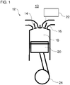
- the figure 1 shows a cylinder 12 of an internal combustion engine 10.
- the internal combustion engine 10 is a four-stroke internal combustion engine, in particular a four-stroke diesel internal combustion engine or a four-stroke gasoline internal combustion engine.
- the internal combustion engine 10 is preferably included in a commercial vehicle, for example a truck or a bus, for driving the commercial vehicle.
- the cylinder 12 includes at least one gas inlet valve 14, at least one gas outlet valve 16, a combustion chamber 18, and a piston 20. As shown in FIG.
- the at least one gas inlet valve 14 connects the combustion chamber 18 to an air supply system of the internal combustion engine 10 for supplying combustion air to the combustion chamber 18.
- the at least one gas outlet valve 16 connects the combustion chamber 18 to an exhaust system of the internal combustion engine 10 for discharging exhaust gases.
- two gas inlet valves 14 and two gas outlet valves 16 per cylinder 12 and a plurality of cylinders 12 can be provided.
- the at least one gas outlet valve 16 can be actuated via a variable valve train 22 .
- the variable valve train 22 can be designed, for example, as a sliding cam system.
- the sliding cam system can have at least one cam carrier with at least two cams.
- the cam carrier can be arranged on a camshaft in a rotationally fixed and axially displaceable manner.
- the at least one gas exchange valve is actuated by different cams of the cam carrier depending on an axial position of the cam carrier. It is also possible that with several gas outlet valves 16 per cylinder 12, the gas outlet valves 16 of the respective cylinder 12 can be actuated differently.
- the piston 20 is reciprocally disposed within the cylinder 12 and connected to a crankshaft 24 in a known manner.
- FIG. 12 is an example timing diagram for the actuation of the gas inlet valves 14 and the gas outlet valves 16 of FIG figure 1 during engine braking operation of internal combustion engine 10 .
- a dot-dash curve A shows a valve lift of the gas intake valves 14 as a function of a crank angle of the crankshaft 24.
- a dashed curve B shows a valve lift of the gas exhaust valve 16 as a function of the crank angle of the crankshaft 24.
- a solid curve C shows a cylinder pressure in the combustion chamber 18 in Depending on a crank angle of the crankshaft 24 at a low engine speed.
- a dotted curve D shows a cylinder pressure in the combustion chamber 18 versus a crank angle of the crankshaft 24 at a high engine speed.
- the curves A to D are plotted over the 720° crank angle (KW) that is usual in four-stroke operation, with the left-hand axis of the diagram indicating the cylinder pressures in bar and the right-hand axis indicating the valve lifts in mm.
- the gas inlet valves 14 are opened during engine braking operation as well as in regular operation during the intake stroke.
- the gas inlet valves 14 are closed over the further control cycle.
- the gas outlet valves 16 are controlled differently than in regular operation (normal operation), in which the gas outlet valves 16 are only open during the exhaust stroke.
- the internal combustion engine can have two gas outlet valves 16 per cylinder 12, one of which is kept completely closed during engine braking and the other is controlled according to curve B during engine braking.
- the gas outlet valve 16 is approximately 60 ° CA to 100 ° CA before the ignition top dead center, i. H. before the end of the compression stroke, partially open.
- the gas outlet valve 16 is then held partially open for approximately 360° CA during the expansion stroke and the exhaust stroke.
- the partially opened gas outlet valve 16 is closed again after the exhaust stroke and remains closed until it opens again in the compression stroke.
- the gas outlet valve 16 is only partially opened.
- the partial opening can correspond to a valve lift of 0.5 mm to 3 mm.
- a maximum lift (regular lift) of the gas outlet valve 16 can be between approximately 10 mm for small internal combustion engines 10 and up to approximately 16 mm for very large internal combustion engines 10 in commercial vehicle construction.
- Curve C At low speeds of the internal combustion engine 10 up to, for example, approximately 1200 rpm, there is no compression in the combustion chamber 18 during the exhaust stroke. This is due to the valve gap created by the partially open gas outlet valve 16. This valve gap is sufficient at low piston 20 speeds to allow the gas in the combustion chamber 18 to flow out of the combustion chamber 18 through the partially open gas outlet valve 16 without a pressure increase.
- Curve C relates, for example, to a cylinder pressure profile at an engine speed of the internal combustion engine of approximately 600 rpm.
- Curve D relates, for example, to a cylinder pressure profile at an engine speed of the internal combustion engine of approximately 2600 rpm.
- a transition between the curves C and D occurs steadily as the engine speed of the internal combustion engine 10 increases.
- the invention thus makes it possible in a particularly advantageous manner for a high braking effect to be achieved by double compression-decompression with one and the same control profile for a gas outlet valve 16 at high speeds of the internal combustion engine 10 (curve D).
- a (small) braking effect is also achieved through the one-time compression-decompression (curve C), with engine excitation being prevented or at least reduced due to the omission of the second compression-decompression.
- the method thus adapts itself to the ambient conditions (the engine speed), so that no additional external control intervention is necessary.
Landscapes
- Engineering & Computer Science (AREA)
- Mechanical Engineering (AREA)
- General Engineering & Computer Science (AREA)
- Chemical & Material Sciences (AREA)
- Combustion & Propulsion (AREA)
- Output Control And Ontrol Of Special Type Engine (AREA)
- Valve Device For Special Equipments (AREA)
Claims (12)
- Procédé de freinage d'un moteur à combustion interne (10), notamment d'un moteur à combustion interne à quatre temps, ledit procédé comprenant les étapes suivantes :ouvrir partiellement au moins une soupape de sortie de gaz (16) d'au moins un cylindre (12) du moteur à combustion interne (10) pendant un temps de compression du moteur à combustion interne (10) ;maintenir une ouverture partielle de l'au moins une soupape de sortie de gaz (16) pendant un temps de détente du moteur à combustion interne (10) qui fait suite au temps de compression et pendant un temps d'échappement du moteur à combustion interne (10) qui fait suite au temps de détente ; etfermer l'au moins une soupape de sortie de gaz (16), partiellement ouverte, à la fin du temps d'échappement ou pendant un temps d'admission du moteur à combustion interne (10) qui fait suite au temps d'échappement,caractérisé en ce quel'au moins une soupape de sortie de gaz (16) est ouverte lors de l'ouverture partielle tant que, lorsque la vitesse de rotation du moteur à combustion interne (10) est inférieure à une vitesse de rotation limite du moteur à combustion interne (10), il n'y a sensiblement aucune compression dans le cylindre respectif (12) pendant le temps d'échappement,l'au moins une soupape de sortie de gaz (16) est ouverte lors de l'ouverture partielle tant que, lorsque la vitesse de rotation du moteur à combustion interne (10) est supérieure à la vitesse de rotation limite, une compression se produit dans le cylindre respectif (12) pendant le temps d'échappement, etla vitesse de rotation limite est située dans une plage comprise entre 1000 tr/min et 1700 tr/min, en particulier dans une plage comprise entre 1200 tr/min et 1500 tr/min.
- Procédé selon la revendication 1,
la compression dans le cylindre respectif (12) augmentant au-dessus de la vitesse de rotation limite pendant le temps d'échappement à mesure que la vitesse du moteur à combustion interne (10) augmente. - Procédé selon l'une des revendications précédentes,l'au moins une soupape de sortie de gaz (16) étant ouverte lors de l'ouverture partielle dans une plage comprise entre 5 % et 30 % d'une levée de soupape maximale de l'au moins une soupape de sortie de gaz (16) ; et/oul'au moins une soupape de sortie de gaz (16) étant ouverte lors de l'ouverture partielle dans une plage comprise entre 0,5 mm et 3 mm.
- Procédé selon la revendication 3, une levée de soupape maximale étant située dans une plage comprise entre 10 mm et 16 mm.
- Procédé selon l'une des revendications précédentes,
l'ouverture partielle de l'au moins une soupape de sortie de gaz (16) pendant le temps de compression commençant dans une plage comprise entre 100° AC et 60° AC avant le PMH. - Procédé selon l'une des revendications précédentes,
la fermeture de l'au moins une soupape de sortie de gaz (16) commençant à la fin du temps d'échappement ou pendant le temps d'admission dans une plage comprise entre le PMH et 30° AC après le PMH. - Procédé selon l'une des revendications précédentes,
lorsque la soupape de sortie de gaz (16) est maintenue ouverte pendant le temps de détente et le temps d'échappement, une levée de soupape constante de l'au moins une soupape de sortie de gaz (16) étant maintenue. - Procédé selon l'une des revendications précédentes,
deux soupapes de sortie de gaz (16) étant prévues pour chaque cylindre (12) et une seule des deux soupapes de sortie de gaz (16) étant partiellement ouverte pendant le temps de compression, étant maintenue ouverte avec une ouverture partielle pendant le temps de détente et le temps d'échappement et étant fermée à la fin du temps d'échappement ou pendant le temps d'admission. - Procédé selon la revendication 8,
l'autre des deux soupapes de sortie de gaz (16) étant fermée pendant le temps de compression, le temps de détente, le temps d'échappement et le temps d'admission. - Procédé selon l'une des revendications précédentes, comprenant en outre les étapes suivantes :ouvrir au moins une soupape d'admission de gaz (14) de l'au moins un cylindre (12) pendant un temps d'admission ; etmaintenir l'au moins une soupape d'admission de gaz (14) fermée pendant le temps de compression, le temps de détente et le temps d'échappement.
- Commande de soupapes variable (22), notamment système à cames coulissantes, destinée à un moteur à combustion interne (10), la commande de soupapes variable (22) étant conçue pour mettre en œuvre le procédé selon l'une des revendications précédentes.
- Véhicule automobile, en particulier véhicule utilitaire, comprenant un moteur à combustion interne (10) muni de la commande de soupapes variable selon la revendication 11.
Applications Claiming Priority (1)
| Application Number | Priority Date | Filing Date | Title |
|---|---|---|---|
| DE102017120150.5A DE102017120150A1 (de) | 2017-09-01 | 2017-09-01 | Verfahren zum Bremsen einer Brennkraftmaschine |
Publications (2)
| Publication Number | Publication Date |
|---|---|
| EP3450732A1 EP3450732A1 (fr) | 2019-03-06 |
| EP3450732B1 true EP3450732B1 (fr) | 2022-07-06 |
Family
ID=63311919
Family Applications (1)
| Application Number | Title | Priority Date | Filing Date |
|---|---|---|---|
| EP18189788.5A Active EP3450732B1 (fr) | 2017-09-01 | 2018-08-20 | Procédé de freinage d'un moteur à combustion interne |
Country Status (4)
| Country | Link |
|---|---|
| US (1) | US10738717B2 (fr) |
| EP (1) | EP3450732B1 (fr) |
| CN (1) | CN109611223B (fr) |
| DE (1) | DE102017120150A1 (fr) |
Families Citing this family (3)
| Publication number | Priority date | Publication date | Assignee | Title |
|---|---|---|---|---|
| CN109736958A (zh) * | 2019-03-21 | 2019-05-10 | 潍柴动力股份有限公司 | 一种提高发动机制动功率的方法 |
| SE2151088A1 (en) * | 2021-08-31 | 2023-03-01 | Scania Cv Ab | Method for Controlling Powertrain of Vehicle, Computer Program, Computer-Readable Medium, Control Arrangement, Powertrain, and Vehicle |
| DE102022110795A1 (de) | 2021-09-17 | 2023-03-23 | Schaeffler Technologies AG & Co. KG | Viertakt-Brennkraftmaschine und Verfahren zum Betrieb einer Viertakt-Brennkraftmaschine |
Family Cites Families (24)
| Publication number | Priority date | Publication date | Assignee | Title |
|---|---|---|---|---|
| US3786792A (en) * | 1971-05-28 | 1974-01-22 | Mack Trucks | Variable valve timing system |
| US4592319A (en) * | 1985-08-09 | 1986-06-03 | The Jacobs Manufacturing Company | Engine retarding method and apparatus |
| US4793307A (en) * | 1987-06-11 | 1988-12-27 | The Jacobs Manufacturing Company | Rocker arm decoupler for two-cycle engine retarder |
| DE3922884A1 (de) | 1989-07-12 | 1991-01-24 | Man Nutzfahrzeuge Ag | Motorbremse fuer luftverdichtende brennkraftmaschinen |
| JPH06241075A (ja) * | 1993-02-16 | 1994-08-30 | Hino Motors Ltd | 自動変速装置 |
| JPH08338215A (ja) * | 1995-06-15 | 1996-12-24 | Unisia Jecs Corp | デコンプレッションブレーキ装置 |
| US5586531A (en) | 1995-11-28 | 1996-12-24 | Cummins Engine Company, Inc. | Engine retarder cycle |
| DE19637998A1 (de) * | 1996-09-18 | 1998-03-19 | Daimler Benz Ag | Motorbremsvorrichtung für eine Brennkraftmaschine |
| US8820276B2 (en) * | 1997-12-11 | 2014-09-02 | Jacobs Vehicle Systems, Inc. | Variable lost motion valve actuator and method |
| US6269793B1 (en) * | 1999-10-04 | 2001-08-07 | Ford Global Technologies, Inc. | Internal combustion engine having deceleration fuel shut off and camshaft controlled charge trapping |
| US6594996B2 (en) * | 2001-05-22 | 2003-07-22 | Diesel Engine Retarders, Inc | Method and system for engine braking in an internal combustion engine with exhaust pressure regulation and turbocharger control |
| US7162996B2 (en) * | 2002-12-23 | 2007-01-16 | Jacobs Vehicle Systems, Inc. | Engine braking methods and apparatus |
| US6925976B2 (en) * | 2003-03-06 | 2005-08-09 | Jenara Enterprises Ltd. | Modal variable valve actuation system for internal combustion engine and method for operating the same |
| DE102004030452A1 (de) * | 2004-06-24 | 2006-01-12 | Robert Bosch Gmbh | Verfahren und Vorrichtung zum Betreiben einer Brennkraftmaschine |
| AT500601B1 (de) | 2004-07-16 | 2006-11-15 | Avl List Gmbh | Verfahren zum betreiben einer brennkraftmaschine |
| JP4483759B2 (ja) * | 2005-10-12 | 2010-06-16 | トヨタ自動車株式会社 | 内燃機関の制御装置 |
| DE102005059403A1 (de) * | 2005-12-13 | 2007-06-14 | Daimlerchrysler Ag | Im Zweitaktverfahren durchzuführendes Motorbremsverfahren für eine Brennkraftmaschine |
| WO2009136900A2 (fr) * | 2007-02-21 | 2009-11-12 | Jacobs Vehicle Systems, Inc. | Procédé de contrôle de température des gaz d’échappement par freinage de moteur dans un moteur à combustion interne |
| US7789065B2 (en) * | 2008-07-09 | 2010-09-07 | Zhou Yang | Engine braking apparatus with mechanical linkage and lash adjustment |
| US8746190B2 (en) * | 2010-11-15 | 2014-06-10 | Achates Power, Inc. | Two stroke opposed-piston engines with compression release for engine braking |
| US9376941B2 (en) * | 2011-02-15 | 2016-06-28 | Shanghai Universoon Autoparts Co., Ltd. | Method and apparatus for resetting valve lift for use in engine brake |
| KR101633042B1 (ko) * | 2012-02-23 | 2016-06-23 | 자콥스 비히클 시스템즈, 인코포레이티드. | 조기 배기 밸브 개방을 위한 엔진 브레이킹 메커니즘을 사용한 엔진 시스템 및 작동 방법 |
| DE102013019183A1 (de) | 2013-11-18 | 2015-05-21 | Man Truck & Bus Ag | Verfahren zum Steuern der Motorbremswirkung einer ventilgesteuerten Brennkraftrnaschine |
| DE102015016526A1 (de) | 2015-12-19 | 2017-06-22 | Daimler Ag | Verfahren zum Betreiben einer Hubkolben-Verbrennungskraftmaschine |
-
2017
- 2017-09-01 DE DE102017120150.5A patent/DE102017120150A1/de not_active Withdrawn
-
2018
- 2018-08-20 EP EP18189788.5A patent/EP3450732B1/fr active Active
- 2018-08-31 US US16/119,211 patent/US10738717B2/en active Active
- 2018-09-03 CN CN201811019496.1A patent/CN109611223B/zh active Active
Also Published As
| Publication number | Publication date |
|---|---|
| DE102017120150A1 (de) | 2019-03-07 |
| RU2018131464A (ru) | 2020-03-03 |
| US10738717B2 (en) | 2020-08-11 |
| CN109611223A (zh) | 2019-04-12 |
| CN109611223B (zh) | 2022-09-27 |
| RU2018131464A3 (fr) | 2021-12-28 |
| US20190072042A1 (en) | 2019-03-07 |
| BR102018067605A2 (pt) | 2019-04-24 |
| EP3450732A1 (fr) | 2019-03-06 |
Similar Documents
| Publication | Publication Date | Title |
|---|---|---|
| DE69003094T2 (de) | Verfahren und vorrichtung zum bremsen eines viertaktverbrennungsmotors. | |
| AT510237B1 (de) | Verfahren zur motorbremsung | |
| DE3922884C2 (fr) | ||
| WO2007090532A1 (fr) | Moteur à combustion interne | |
| EP1276980A1 (fr) | Procede pour commander le remplissage des cylindres dans un moteur a combustion interne | |
| EP3450732B1 (fr) | Procédé de freinage d'un moteur à combustion interne | |
| DE102011114065A1 (de) | Verfahren zum Betreiben einer Brennkraftmaschine | |
| WO2008017440A1 (fr) | Moteur à combustion interne | |
| EP1439295B1 (fr) | Procédé de contrôle de l'arrêt d'un moteur à combustion interne | |
| DE102013019183A1 (de) | Verfahren zum Steuern der Motorbremswirkung einer ventilgesteuerten Brennkraftrnaschine | |
| EP3536917B1 (fr) | Mécanisme de soupapes variable pourvu de système de cames coulissantes pour un moteur à combustion interne | |
| EP1754872B1 (fr) | Moteur Otto avec soupapes à commande variable et fonctionnenment à cycle Atkinson | |
| EP3084197B1 (fr) | Procédé de fonctionnement d'un moteur à combustion interne à pistons alternatifs | |
| DE102014208950A1 (de) | Verbrennungsmotor und Verfahren zum Betreiben eines solchen Verbrennungsmotors | |
| DE102004030452A1 (de) | Verfahren und Vorrichtung zum Betreiben einer Brennkraftmaschine | |
| EP1840352B1 (fr) | Système d'alimentation d'air frais et méthode d'opération pour un moteur à piston | |
| DE102004052670A1 (de) | Verfahren zum Betrieb einer Brennkraftmaschine im Motorbremsbetrieb | |
| EP3536938B1 (fr) | Procédé de fonctionnement d'un moteur à combustion interne permettant d'augmenter une température de gaz d'échappement | |
| DE102015205297A1 (de) | Brennkraftmaschine | |
| DE102004005588A1 (de) | Schaltbare Nockenwelle zur Änderung der Nockenerhebungsdauer | |
| DE102019005128A1 (de) | Verfahren zum Betreiben einer Verbrennungskraftmaschine eines Kraftfahrzeugs, insbesondere eines Kraftwagens | |
| DE102024129431A1 (de) | Brennkraftmaschine mit mehreren unabhängig voneinander betreibbaren Motorbremsen | |
| DE102019206158A1 (de) | Verfahren zum Betreiben einer Hubkolbenbrennkraftmaschine mit Zylinderabschaltung und Ventilvariabilität sowie Hubkolbenbrennkraftmaschine | |
| DE102016015457A1 (de) | Verfahren zum Betreiben einer Hubkolben-Verbrennungskraftmaschine | |
| DE102019216361A1 (de) | Verfahren zur Ventilsteuerung zum schnellen Aufheizen der Abgasanlage |
Legal Events
| Date | Code | Title | Description |
|---|---|---|---|
| PUAI | Public reference made under article 153(3) epc to a published international application that has entered the european phase |
Free format text: ORIGINAL CODE: 0009012 |
|
| STAA | Information on the status of an ep patent application or granted ep patent |
Free format text: STATUS: THE APPLICATION HAS BEEN PUBLISHED |
|
| AK | Designated contracting states |
Kind code of ref document: A1 Designated state(s): AL AT BE BG CH CY CZ DE DK EE ES FI FR GB GR HR HU IE IS IT LI LT LU LV MC MK MT NL NO PL PT RO RS SE SI SK SM TR |
|
| AX | Request for extension of the european patent |
Extension state: BA ME |
|
| RAP1 | Party data changed (applicant data changed or rights of an application transferred) |
Owner name: MAN TRUCK & BUS SE |
|
| STAA | Information on the status of an ep patent application or granted ep patent |
Free format text: STATUS: REQUEST FOR EXAMINATION WAS MADE |
|
| 17P | Request for examination filed |
Effective date: 20190902 |
|
| RBV | Designated contracting states (corrected) |
Designated state(s): AL AT BE BG CH CY CZ DE DK EE ES FI FR GB GR HR HU IE IS IT LI LT LU LV MC MK MT NL NO PL PT RO RS SE SI SK SM TR |
|
| GRAP | Despatch of communication of intention to grant a patent |
Free format text: ORIGINAL CODE: EPIDOSNIGR1 |
|
| STAA | Information on the status of an ep patent application or granted ep patent |
Free format text: STATUS: GRANT OF PATENT IS INTENDED |
|
| INTG | Intention to grant announced |
Effective date: 20220207 |
|
| GRAS | Grant fee paid |
Free format text: ORIGINAL CODE: EPIDOSNIGR3 |
|
| GRAA | (expected) grant |
Free format text: ORIGINAL CODE: 0009210 |
|
| STAA | Information on the status of an ep patent application or granted ep patent |
Free format text: STATUS: THE PATENT HAS BEEN GRANTED |
|
| AK | Designated contracting states |
Kind code of ref document: B1 Designated state(s): AL AT BE BG CH CY CZ DE DK EE ES FI FR GB GR HR HU IE IS IT LI LT LU LV MC MK MT NL NO PL PT RO RS SE SI SK SM TR |
|
| REG | Reference to a national code |
Ref country code: AT Ref legal event code: REF Ref document number: 1503032 Country of ref document: AT Kind code of ref document: T Effective date: 20220715 Ref country code: CH Ref legal event code: EP |
|
| REG | Reference to a national code |
Ref country code: DE Ref legal event code: R096 Ref document number: 502018010078 Country of ref document: DE |
|
| REG | Reference to a national code |
Ref country code: IE Ref legal event code: FG4D Free format text: LANGUAGE OF EP DOCUMENT: GERMAN |
|
| REG | Reference to a national code |
Ref country code: NL Ref legal event code: FP |
|
| REG | Reference to a national code |
Ref country code: SE Ref legal event code: TRGR |
|
| REG | Reference to a national code |
Ref country code: LT Ref legal event code: MG9D |
|
| PG25 | Lapsed in a contracting state [announced via postgrant information from national office to epo] |
Ref country code: RS Free format text: LAPSE BECAUSE OF FAILURE TO SUBMIT A TRANSLATION OF THE DESCRIPTION OR TO PAY THE FEE WITHIN THE PRESCRIBED TIME-LIMIT Effective date: 20220706 Ref country code: PT Free format text: LAPSE BECAUSE OF FAILURE TO SUBMIT A TRANSLATION OF THE DESCRIPTION OR TO PAY THE FEE WITHIN THE PRESCRIBED TIME-LIMIT Effective date: 20221107 Ref country code: NO Free format text: LAPSE BECAUSE OF FAILURE TO SUBMIT A TRANSLATION OF THE DESCRIPTION OR TO PAY THE FEE WITHIN THE PRESCRIBED TIME-LIMIT Effective date: 20221006 Ref country code: LV Free format text: LAPSE BECAUSE OF FAILURE TO SUBMIT A TRANSLATION OF THE DESCRIPTION OR TO PAY THE FEE WITHIN THE PRESCRIBED TIME-LIMIT Effective date: 20220706 Ref country code: LT Free format text: LAPSE BECAUSE OF FAILURE TO SUBMIT A TRANSLATION OF THE DESCRIPTION OR TO PAY THE FEE WITHIN THE PRESCRIBED TIME-LIMIT Effective date: 20220706 Ref country code: FI Free format text: LAPSE BECAUSE OF FAILURE TO SUBMIT A TRANSLATION OF THE DESCRIPTION OR TO PAY THE FEE WITHIN THE PRESCRIBED TIME-LIMIT Effective date: 20220706 Ref country code: ES Free format text: LAPSE BECAUSE OF FAILURE TO SUBMIT A TRANSLATION OF THE DESCRIPTION OR TO PAY THE FEE WITHIN THE PRESCRIBED TIME-LIMIT Effective date: 20220706 |
|
| PG25 | Lapsed in a contracting state [announced via postgrant information from national office to epo] |
Ref country code: PL Free format text: LAPSE BECAUSE OF FAILURE TO SUBMIT A TRANSLATION OF THE DESCRIPTION OR TO PAY THE FEE WITHIN THE PRESCRIBED TIME-LIMIT Effective date: 20220706 Ref country code: IS Free format text: LAPSE BECAUSE OF FAILURE TO SUBMIT A TRANSLATION OF THE DESCRIPTION OR TO PAY THE FEE WITHIN THE PRESCRIBED TIME-LIMIT Effective date: 20221106 Ref country code: GR Free format text: LAPSE BECAUSE OF FAILURE TO SUBMIT A TRANSLATION OF THE DESCRIPTION OR TO PAY THE FEE WITHIN THE PRESCRIBED TIME-LIMIT Effective date: 20221007 |
|
| REG | Reference to a national code |
Ref country code: CH Ref legal event code: PL |
|
| REG | Reference to a national code |
Ref country code: DE Ref legal event code: R097 Ref document number: 502018010078 Country of ref document: DE |
|
| PG25 | Lapsed in a contracting state [announced via postgrant information from national office to epo] |
Ref country code: SM Free format text: LAPSE BECAUSE OF FAILURE TO SUBMIT A TRANSLATION OF THE DESCRIPTION OR TO PAY THE FEE WITHIN THE PRESCRIBED TIME-LIMIT Effective date: 20220706 Ref country code: RO Free format text: LAPSE BECAUSE OF FAILURE TO SUBMIT A TRANSLATION OF THE DESCRIPTION OR TO PAY THE FEE WITHIN THE PRESCRIBED TIME-LIMIT Effective date: 20220706 Ref country code: MC Free format text: LAPSE BECAUSE OF FAILURE TO SUBMIT A TRANSLATION OF THE DESCRIPTION OR TO PAY THE FEE WITHIN THE PRESCRIBED TIME-LIMIT Effective date: 20220706 Ref country code: LU Free format text: LAPSE BECAUSE OF NON-PAYMENT OF DUE FEES Effective date: 20220820 Ref country code: LI Free format text: LAPSE BECAUSE OF NON-PAYMENT OF DUE FEES Effective date: 20220831 Ref country code: DK Free format text: LAPSE BECAUSE OF FAILURE TO SUBMIT A TRANSLATION OF THE DESCRIPTION OR TO PAY THE FEE WITHIN THE PRESCRIBED TIME-LIMIT Effective date: 20220706 Ref country code: CZ Free format text: LAPSE BECAUSE OF FAILURE TO SUBMIT A TRANSLATION OF THE DESCRIPTION OR TO PAY THE FEE WITHIN THE PRESCRIBED TIME-LIMIT Effective date: 20220706 Ref country code: CH Free format text: LAPSE BECAUSE OF NON-PAYMENT OF DUE FEES Effective date: 20220831 |
|
| REG | Reference to a national code |
Ref country code: BE Ref legal event code: MM Effective date: 20220831 |
|
| PLBE | No opposition filed within time limit |
Free format text: ORIGINAL CODE: 0009261 |
|
| STAA | Information on the status of an ep patent application or granted ep patent |
Free format text: STATUS: NO OPPOSITION FILED WITHIN TIME LIMIT |
|
| PG25 | Lapsed in a contracting state [announced via postgrant information from national office to epo] |
Ref country code: SK Free format text: LAPSE BECAUSE OF FAILURE TO SUBMIT A TRANSLATION OF THE DESCRIPTION OR TO PAY THE FEE WITHIN THE PRESCRIBED TIME-LIMIT Effective date: 20220706 Ref country code: EE Free format text: LAPSE BECAUSE OF FAILURE TO SUBMIT A TRANSLATION OF THE DESCRIPTION OR TO PAY THE FEE WITHIN THE PRESCRIBED TIME-LIMIT Effective date: 20220706 |
|
| 26N | No opposition filed |
Effective date: 20230411 |
|
| PG25 | Lapsed in a contracting state [announced via postgrant information from national office to epo] |
Ref country code: AL Free format text: LAPSE BECAUSE OF FAILURE TO SUBMIT A TRANSLATION OF THE DESCRIPTION OR TO PAY THE FEE WITHIN THE PRESCRIBED TIME-LIMIT Effective date: 20220706 |
|
| PG25 | Lapsed in a contracting state [announced via postgrant information from national office to epo] |
Ref country code: IE Free format text: LAPSE BECAUSE OF NON-PAYMENT OF DUE FEES Effective date: 20220820 |
|
| PG25 | Lapsed in a contracting state [announced via postgrant information from national office to epo] |
Ref country code: SI Free format text: LAPSE BECAUSE OF FAILURE TO SUBMIT A TRANSLATION OF THE DESCRIPTION OR TO PAY THE FEE WITHIN THE PRESCRIBED TIME-LIMIT Effective date: 20220706 |
|
| PG25 | Lapsed in a contracting state [announced via postgrant information from national office to epo] |
Ref country code: BE Free format text: LAPSE BECAUSE OF NON-PAYMENT OF DUE FEES Effective date: 20220831 |
|
| PG25 | Lapsed in a contracting state [announced via postgrant information from national office to epo] |
Ref country code: HU Free format text: LAPSE BECAUSE OF FAILURE TO SUBMIT A TRANSLATION OF THE DESCRIPTION OR TO PAY THE FEE WITHIN THE PRESCRIBED TIME-LIMIT; INVALID AB INITIO Effective date: 20180820 |
|
| PG25 | Lapsed in a contracting state [announced via postgrant information from national office to epo] |
Ref country code: HR Free format text: LAPSE BECAUSE OF FAILURE TO SUBMIT A TRANSLATION OF THE DESCRIPTION OR TO PAY THE FEE WITHIN THE PRESCRIBED TIME-LIMIT Effective date: 20220706 Ref country code: CY Free format text: LAPSE BECAUSE OF FAILURE TO SUBMIT A TRANSLATION OF THE DESCRIPTION OR TO PAY THE FEE WITHIN THE PRESCRIBED TIME-LIMIT Effective date: 20220706 |
|
| PG25 | Lapsed in a contracting state [announced via postgrant information from national office to epo] |
Ref country code: MK Free format text: LAPSE BECAUSE OF FAILURE TO SUBMIT A TRANSLATION OF THE DESCRIPTION OR TO PAY THE FEE WITHIN THE PRESCRIBED TIME-LIMIT Effective date: 20220706 |
|
| PG25 | Lapsed in a contracting state [announced via postgrant information from national office to epo] |
Ref country code: TR Free format text: LAPSE BECAUSE OF FAILURE TO SUBMIT A TRANSLATION OF THE DESCRIPTION OR TO PAY THE FEE WITHIN THE PRESCRIBED TIME-LIMIT Effective date: 20220706 |
|
| PG25 | Lapsed in a contracting state [announced via postgrant information from national office to epo] |
Ref country code: BG Free format text: LAPSE BECAUSE OF FAILURE TO SUBMIT A TRANSLATION OF THE DESCRIPTION OR TO PAY THE FEE WITHIN THE PRESCRIBED TIME-LIMIT Effective date: 20220706 |
|
| PG25 | Lapsed in a contracting state [announced via postgrant information from national office to epo] |
Ref country code: MT Free format text: LAPSE BECAUSE OF FAILURE TO SUBMIT A TRANSLATION OF THE DESCRIPTION OR TO PAY THE FEE WITHIN THE PRESCRIBED TIME-LIMIT Effective date: 20220706 |
|
| REG | Reference to a national code |
Ref country code: AT Ref legal event code: MM01 Ref document number: 1503032 Country of ref document: AT Kind code of ref document: T Effective date: 20230820 |
|
| PG25 | Lapsed in a contracting state [announced via postgrant information from national office to epo] |
Ref country code: AT Free format text: LAPSE BECAUSE OF NON-PAYMENT OF DUE FEES Effective date: 20230820 |
|
| PG25 | Lapsed in a contracting state [announced via postgrant information from national office to epo] |
Ref country code: AT Free format text: LAPSE BECAUSE OF NON-PAYMENT OF DUE FEES Effective date: 20230820 |
|
| PGFP | Annual fee paid to national office [announced via postgrant information from national office to epo] |
Ref country code: NL Payment date: 20250825 Year of fee payment: 8 |
|
| PGFP | Annual fee paid to national office [announced via postgrant information from national office to epo] |
Ref country code: DE Payment date: 20250827 Year of fee payment: 8 |
|
| PGFP | Annual fee paid to national office [announced via postgrant information from national office to epo] |
Ref country code: IT Payment date: 20250825 Year of fee payment: 8 |
|
| PGFP | Annual fee paid to national office [announced via postgrant information from national office to epo] |
Ref country code: GB Payment date: 20250826 Year of fee payment: 8 |
|
| PGFP | Annual fee paid to national office [announced via postgrant information from national office to epo] |
Ref country code: FR Payment date: 20250825 Year of fee payment: 8 |
|
| PGFP | Annual fee paid to national office [announced via postgrant information from national office to epo] |
Ref country code: SE Payment date: 20250825 Year of fee payment: 8 |
|
| PGFP | Annual fee paid to national office [announced via postgrant information from national office to epo] |
Ref country code: AT Payment date: 20260410 Year of fee payment: 5 |