EP3450754A1 - Offener kältemittelverdichter - Google Patents
Offener kältemittelverdichter Download PDFInfo
- Publication number
- EP3450754A1 EP3450754A1 EP17839316.1A EP17839316A EP3450754A1 EP 3450754 A1 EP3450754 A1 EP 3450754A1 EP 17839316 A EP17839316 A EP 17839316A EP 3450754 A1 EP3450754 A1 EP 3450754A1
- Authority
- EP
- European Patent Office
- Prior art keywords
- drive shaft
- refrigerant
- guide groove
- bearing
- press
- Prior art date
- Legal status (The legal status is an assumption and is not a legal conclusion. Google has not performed a legal analysis and makes no representation as to the accuracy of the status listed.)
- Withdrawn
Links
- 239000003507 refrigerant Substances 0.000 title claims abstract description 124
- 238000005096 rolling process Methods 0.000 claims abstract description 52
- 230000002093 peripheral effect Effects 0.000 claims description 30
- 230000006835 compression Effects 0.000 claims description 29
- 238000007906 compression Methods 0.000 claims description 29
- 239000000314 lubricant Substances 0.000 claims description 13
- 230000001050 lubricating effect Effects 0.000 abstract description 2
- 238000007789 sealing Methods 0.000 abstract 2
- 230000006866 deterioration Effects 0.000 abstract 1
- 239000010687 lubricating oil Substances 0.000 abstract 1
- 230000007423 decrease Effects 0.000 description 13
- 238000005461 lubrication Methods 0.000 description 9
- 230000003247 decreasing effect Effects 0.000 description 7
- 239000003921 oil Substances 0.000 description 4
- 230000000694 effects Effects 0.000 description 3
- 229910000838 Al alloy Inorganic materials 0.000 description 2
- 230000015572 biosynthetic process Effects 0.000 description 2
- 239000010721 machine oil Substances 0.000 description 2
- 239000003595 mist Substances 0.000 description 2
- 238000012986 modification Methods 0.000 description 2
- 230000004048 modification Effects 0.000 description 2
- 230000002265 prevention Effects 0.000 description 2
- 238000004378 air conditioning Methods 0.000 description 1
- 238000001816 cooling Methods 0.000 description 1
- 238000007710 freezing Methods 0.000 description 1
- 230000008014 freezing Effects 0.000 description 1
- XLYOFNOQVPJJNP-UHFFFAOYSA-N water Substances O XLYOFNOQVPJJNP-UHFFFAOYSA-N 0.000 description 1
Images




Classifications
-
- F—MECHANICAL ENGINEERING; LIGHTING; HEATING; WEAPONS; BLASTING
- F04—POSITIVE - DISPLACEMENT MACHINES FOR LIQUIDS; PUMPS FOR LIQUIDS OR ELASTIC FLUIDS
- F04B—POSITIVE-DISPLACEMENT MACHINES FOR LIQUIDS; PUMPS
- F04B39/00—Component parts, details, or accessories, of pumps or pumping systems specially adapted for elastic fluids, not otherwise provided for in, or of interest apart from, groups F04B25/00 - F04B37/00
- F04B39/02—Lubrication
-
- F—MECHANICAL ENGINEERING; LIGHTING; HEATING; WEAPONS; BLASTING
- F04—POSITIVE - DISPLACEMENT MACHINES FOR LIQUIDS; PUMPS FOR LIQUIDS OR ELASTIC FLUIDS
- F04B—POSITIVE-DISPLACEMENT MACHINES FOR LIQUIDS; PUMPS
- F04B39/00—Component parts, details, or accessories, of pumps or pumping systems specially adapted for elastic fluids, not otherwise provided for in, or of interest apart from, groups F04B25/00 - F04B37/00
-
- F—MECHANICAL ENGINEERING; LIGHTING; HEATING; WEAPONS; BLASTING
- F04—POSITIVE - DISPLACEMENT MACHINES FOR LIQUIDS; PUMPS FOR LIQUIDS OR ELASTIC FLUIDS
- F04B—POSITIVE-DISPLACEMENT MACHINES FOR LIQUIDS; PUMPS
- F04B1/00—Multi-cylinder machines or pumps characterised by number or arrangement of cylinders
- F04B1/12—Multi-cylinder machines or pumps characterised by number or arrangement of cylinders having cylinder axes coaxial with, or parallel or inclined to, main shaft axis
- F04B1/14—Multi-cylinder machines or pumps characterised by number or arrangement of cylinders having cylinder axes coaxial with, or parallel or inclined to, main shaft axis having stationary cylinders
- F04B1/141—Details or component parts
- F04B1/146—Swash plates; Actuating elements
- F04B1/148—Bearings therefor
-
- F—MECHANICAL ENGINEERING; LIGHTING; HEATING; WEAPONS; BLASTING
- F04—POSITIVE - DISPLACEMENT MACHINES FOR LIQUIDS; PUMPS FOR LIQUIDS OR ELASTIC FLUIDS
- F04B—POSITIVE-DISPLACEMENT MACHINES FOR LIQUIDS; PUMPS
- F04B1/00—Multi-cylinder machines or pumps characterised by number or arrangement of cylinders
- F04B1/12—Multi-cylinder machines or pumps characterised by number or arrangement of cylinders having cylinder axes coaxial with, or parallel or inclined to, main shaft axis
- F04B1/20—Multi-cylinder machines or pumps characterised by number or arrangement of cylinders having cylinder axes coaxial with, or parallel or inclined to, main shaft axis having rotary cylinder block
- F04B1/2014—Details or component parts
- F04B1/2078—Swash plates
- F04B1/2085—Bearings for swash plates or driving axles
-
- F—MECHANICAL ENGINEERING; LIGHTING; HEATING; WEAPONS; BLASTING
- F04—POSITIVE - DISPLACEMENT MACHINES FOR LIQUIDS; PUMPS FOR LIQUIDS OR ELASTIC FLUIDS
- F04B—POSITIVE-DISPLACEMENT MACHINES FOR LIQUIDS; PUMPS
- F04B27/00—Multi-cylinder pumps specially adapted for elastic fluids and characterised by number or arrangement of cylinders
- F04B27/08—Multi-cylinder pumps specially adapted for elastic fluids and characterised by number or arrangement of cylinders having cylinders coaxial with, or parallel or inclined to, main shaft axis
- F04B27/0804—Multi-cylinder pumps specially adapted for elastic fluids and characterised by number or arrangement of cylinders having cylinders coaxial with, or parallel or inclined to, main shaft axis having rotary cylinder block
- F04B27/0821—Multi-cylinder pumps specially adapted for elastic fluids and characterised by number or arrangement of cylinders having cylinders coaxial with, or parallel or inclined to, main shaft axis having rotary cylinder block component parts, details, e.g. valves, sealings, lubrication
- F04B27/0826—Multi-cylinder pumps specially adapted for elastic fluids and characterised by number or arrangement of cylinders having cylinders coaxial with, or parallel or inclined to, main shaft axis having rotary cylinder block component parts, details, e.g. valves, sealings, lubrication particularities in the contacting area between cylinder barrel and valve plate
- F04B27/083—Multi-cylinder pumps specially adapted for elastic fluids and characterised by number or arrangement of cylinders having cylinders coaxial with, or parallel or inclined to, main shaft axis having rotary cylinder block component parts, details, e.g. valves, sealings, lubrication particularities in the contacting area between cylinder barrel and valve plate bearing means
-
- F—MECHANICAL ENGINEERING; LIGHTING; HEATING; WEAPONS; BLASTING
- F04—POSITIVE - DISPLACEMENT MACHINES FOR LIQUIDS; PUMPS FOR LIQUIDS OR ELASTIC FLUIDS
- F04B—POSITIVE-DISPLACEMENT MACHINES FOR LIQUIDS; PUMPS
- F04B27/00—Multi-cylinder pumps specially adapted for elastic fluids and characterised by number or arrangement of cylinders
- F04B27/08—Multi-cylinder pumps specially adapted for elastic fluids and characterised by number or arrangement of cylinders having cylinders coaxial with, or parallel or inclined to, main shaft axis
- F04B27/10—Multi-cylinder pumps specially adapted for elastic fluids and characterised by number or arrangement of cylinders having cylinders coaxial with, or parallel or inclined to, main shaft axis having stationary cylinders
- F04B27/1036—Component parts, details, e.g. sealings, lubrication
- F04B27/1054—Actuating elements
- F04B27/1063—Actuating-element bearing means or driving-axis bearing means
-
- F—MECHANICAL ENGINEERING; LIGHTING; HEATING; WEAPONS; BLASTING
- F04—POSITIVE - DISPLACEMENT MACHINES FOR LIQUIDS; PUMPS FOR LIQUIDS OR ELASTIC FLUIDS
- F04B—POSITIVE-DISPLACEMENT MACHINES FOR LIQUIDS; PUMPS
- F04B27/00—Multi-cylinder pumps specially adapted for elastic fluids and characterised by number or arrangement of cylinders
- F04B27/08—Multi-cylinder pumps specially adapted for elastic fluids and characterised by number or arrangement of cylinders having cylinders coaxial with, or parallel or inclined to, main shaft axis
- F04B27/10—Multi-cylinder pumps specially adapted for elastic fluids and characterised by number or arrangement of cylinders having cylinders coaxial with, or parallel or inclined to, main shaft axis having stationary cylinders
- F04B27/1036—Component parts, details, e.g. sealings, lubrication
- F04B27/109—Lubrication
-
- F—MECHANICAL ENGINEERING; LIGHTING; HEATING; WEAPONS; BLASTING
- F04—POSITIVE - DISPLACEMENT MACHINES FOR LIQUIDS; PUMPS FOR LIQUIDS OR ELASTIC FLUIDS
- F04B—POSITIVE-DISPLACEMENT MACHINES FOR LIQUIDS; PUMPS
- F04B53/00—Component parts, details or accessories not provided for in, or of interest apart from, groups F04B1/00 - F04B23/00 or F04B39/00 - F04B47/00
- F04B53/18—Lubricating
-
- F—MECHANICAL ENGINEERING; LIGHTING; HEATING; WEAPONS; BLASTING
- F04—POSITIVE - DISPLACEMENT MACHINES FOR LIQUIDS; PUMPS FOR LIQUIDS OR ELASTIC FLUIDS
- F04C—ROTARY-PISTON, OR OSCILLATING-PISTON, POSITIVE-DISPLACEMENT MACHINES FOR LIQUIDS; ROTARY-PISTON, OR OSCILLATING-PISTON, POSITIVE-DISPLACEMENT PUMPS
- F04C27/00—Sealing arrangements in rotary-piston pumps specially adapted for elastic fluids
-
- F—MECHANICAL ENGINEERING; LIGHTING; HEATING; WEAPONS; BLASTING
- F04—POSITIVE - DISPLACEMENT MACHINES FOR LIQUIDS; PUMPS FOR LIQUIDS OR ELASTIC FLUIDS
- F04C—ROTARY-PISTON, OR OSCILLATING-PISTON, POSITIVE-DISPLACEMENT MACHINES FOR LIQUIDS; ROTARY-PISTON, OR OSCILLATING-PISTON, POSITIVE-DISPLACEMENT PUMPS
- F04C29/00—Component parts, details or accessories of pumps or pumping installations, not provided for in groups F04C18/00 - F04C28/00
- F04C29/02—Lubrication; Lubricant separation
Definitions
- the present invention relates to an open type refrigerant compressor in which a rolling bearing for pivotally supporting a drive shaft of a compression mechanism is press-fitted into a housing.
- a compression mechanism which compresses refrigerant gas in a car air conditioner or the like
- a compression mechanism is accommodated inside a housing formed of an aluminum alloy or the like
- a drive shaft driving the compression mechanism protrudes from one side of the housing
- a pulley having an electromagnetic clutch provided on the protrusion portion is driven by an engine or the like via a belt.
- a shaft hole through which the drive shaft protrudes is formed in the housing, and thus, the refrigerant compressor is referred to as an open type refrigerant compressor.
- a refrigerant compressor in which a compression mechanism and a drive motor are housed inside a sealed pressure container is referred to as a closed type refrigerant compressor.
- a lip seal (a shaft seal member having a lip) is provided in a protrusion portion of the drive shaft, that is, the shaft hole of the housing to prevent a refrigerant gas inside the housing from leaking to the outside.
- the lip seal is lubricated by a lubricant (refrigerating machine oil) mixed with the refrigerant gas.
- a lubricant refrigerating machine oil
- oil supplied to the lip seal is insufficient at a low load operation where a circulation amount of the refrigerant gas decreases or the like. In this case, a tip of the lip wears, and there is a concern that the refrigerant gas and the oil leak.
- a guide groove for guiding a refrigerant to an inner peripheral surface of a bearing press-fitting portion of a rolling bearing which pivotally supports a vicinity of a tip of a drive shaft is formed, and one end of the guide groove communicates with a lip seal side, the other end thereof communicates with an inside (compression mechanism side) of a housing. Accordingly, a supply amount of the refrigerant to the lip seal side, that is, a supply amount of a lubricant is stabilized by using the guide groove, and wear of the lip seal is prevented. As shown in Fig. 7 , if a plurality of guide grooves B are formed on an inner peripheral surface of a bearing press-fitting portion A, the supply amount of the lip seal can increase, which is effective for preventing the wear of the lip seal.
- a rolling bearing is press-fitted (generally, press-fitted by shrink fitting) to the inner peripheral surface of the bearing press-fitting portion A in which the plurality of guide grooves B are formed
- an outer ring member C of the rolling bearing tends to spread radially outward inside the bearing press-fitting portion A, and the outer ring member C tends to bulge inside each guide groove B and deform into a petal shape (in Fig. 8 , the petal shape is exaggeratedly shown, but actually, the petal shape cannot be visually confirmed).
- the deformation of the outer ring member C causes a reduction in a radial clearance (a radial play) in a rolling bearing such as a needle bearing which is precisely machined, and thereby, decreases in performance such as an increase in a rotational resistance, occurrence of flaking (a damage of a roller contact surface), occurrence of an uneven rotation (rotational vibration), or a decrease in the number of years of life span occur, and thus, a negligible problem occurs in a refrigerant compressor requiring high rotation accuracy.
- the present invention is made to solve the above-described problems, and an object thereof is to provide an open type refrigerant compressor capable of forming the refrigerant guide groove on the inner peripheral surface of the bearing press-fitting portion to which the rolling bearing is press-fitted without decreasing performance of the rolling bearing and increasing lubrication performance of the rolling bearing and a shaft seal member.
- an open type refrigerant compressor including: a housing; a compression mechanism which is provided inside the housing and compresses a refrigerant gas including a lubricant; a drive shaft which drives the compression mechanism; a rolling bearing which is press-fitted to a shaft hole through which the drive shaft protrudes outward from the housing and pivotally supports the drive shaft; a shaft seal member which is provided in the shaft hole so as to be positioned outside the rolling bearing; and at least one refrigerant guide groove which is formed on an inner peripheral surface of a bearing press-fitting portion to which the rolling bearing is press-fitted, in which the refrigerant guide groove is formed to have a predetermined inclination angle with a center axis direction of the drive shaft.
- the refrigerant guide groove is formed to have the predetermined inclination angle with respect to the center axis direction of the drive shaft. Therefore, when an outer ring member of the rolling bearing press-fitted to the bearing press-fitting portion spreads radially outward, a linear deformation of the outer ring member over the entire length in the center axis direction of the drive shaft is prevented at a predetermined angular position on an outer peripheral surface of the outer ring member.
- a shape of the deformation portion is not a groove shape parallel in the axial direction of the drive shaft and the shape of the deformation portion is a groove shape inclined in the axial direction. Accordingly, rolling members rolling inside the outer ring member do not repeatedly fall into the inside of a deformation groove or do not repeatedly ride over the deformation groove simultaneously over the entire width. In addition, a radial clearance of the rolling bearing is not easily decreased.
- the refrigerant guide groove when viewed in an axial direction of the drive shaft, may include an inner opening portion which is open toward an inside of the housing and an outer opening portion which is open toward the shaft seal member side, and when viewed in the axial direction of the drive shaft, the refrigerant guide groove may be formed such that an opening range of the inner opening portion and an opening range of the outer opening portion do not overlap with each other.
- the refrigerant guide groove may be a spiral groove. Accordingly, it is possible to easily form the refrigerant guide groove by CNC processing.
- the refrigerant guide groove may be formed such that a spiral direction from the inner opening portion toward the outer opening portion is matched with a rotational direction of the drive shaft.
- an interior angle at an intersection between the inner peripheral surface of the bearing press-fitting portion and an inner peripheral surface of the refrigerant guide groove may be an obtuse angle.
- a ratio of a total groove width of the refrigerant guide groove with respect to a circumference of the bearing press-fitting portion may be 30% to 70%.
- the ratio of the total groove width is set to this range, and thus, a groove width of the refrigerant guide groove is widened as much as possible while press fitting strength of the rolling bearing is secured, amounts of the refrigerant gas and the lubricant flowing through the refrigerant guide groove are secured, and thus, it is possible to increase the lubrication performance of the rolling bearing and the shaft seal member.
- the open type refrigerant compressor of the present invention it is possible to form a lubricant guide groove on the inner peripheral surface of the bearing press-fitting portion to which the rolling bearing is press-fitted without decreasing performance of the rolling bearing and to increase lubrication performance of the rolling bearing and the shaft seal member.
- Fig. 1 is a partially longitudinal sectional view of an open type scroll compressor (open type refrigerant compressor) 1 showing an embodiment of the present invention.
- the open type scroll compressor 1 according to the present embodiment is an open type scroll compressor used in a refrigerated/frozen transport vehicle which is installed in an engine room of an automobile and is configured to be driven by engine power so as to compress a refrigerant gas.
- the present invention is not limited to this, and the present invention can also be widely applied to open type compressors used in car air conditioners, living space air conditioning, refrigerating/freezing systems in shops or the like, heat pump type hot water supply systems, or the like.
- the open type scroll compressor 1 includes an approximately cylindrical housing 2 formed of an aluminum alloy or the like.
- the housing 2 includes a housing main body 2A constituting a main body, and a housing cover 2B which is fixed by a bolt or the like so as to airtightly close an opening portion provided on one end of the housing main body 2A. The other end (not shown) of the housing main body 2A is closed.
- a scroll compression mechanism 4 compression mechanism
- a drive shaft 5 which drives the scroll compression mechanism 4 are accommodated in an internal space S1 of the housing 2.
- the drive shaft 5 is rotatably supported via a main bearing 6 and a sub bearing 7 which are rolling bearings.
- the main bearing 6 is press-fitted into a bearing press-fitting portion 2a formed on a rear end portion of the housing cover 2B
- the sub bearing 7 is press-fitted into a bearing press-fitting portion 8a which is provided on a rear half portion of a shaft hole 8 formed in the housing cover 2B.
- a single row deep groove ball bearing is used as the main bearing 6 and a needle bearing is used as the sub bearing 7.
- the present invention is not limited to this, and it is considered that other types of bearings are used.
- the sub bearing 7 is configured to include an outer ring member 7a, an inner ring member 7b, a plurality of roller-shaped rolling members 7c which are disposed between the inner and outer ring members 7a and 7b, and a retainer 7d which holds the plurality of rolling members 7c at equal intervals.
- a lip seal 9 (shaft seal member) which is positioned outside the sub bearing 7 is press-fitted inside the shaft hole 8.
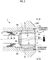
- the lip seal 9 includes two lips 9a and 9b which are inclined toward the sub bearing 7 and are in light contact with an outer peripheral surface of the drive shaft 5 (refer to Fig. 2 ).
- An annular seal space S2 having a predetermined volume is defined between the sub bearing 7 and the lip seal 9.
- a pulley 12 is rotatably installed on a tip outer peripheral portion of the housing cover 2B via a pulley bearing 11, and a belt (not shown) is wound between the pulley 12 and a drive pulley provided in a driving source such as an engine (not shown).
- a clutch plate 13 fixed to a tip portion of the drive shaft 5 faces an outer end surface of the pulley 12 to be close to the outer end surface, and if an electromagnetic clutch 14 fixed to the housing cover 2B so as to be positioned inside the pulley 12 is excited, the clutch plate 13 is pulled toward the pulley 12 side to frictionally engage with the outer end surface of the pulley 12, a rotation of the pulley 12 is transmitted to the drive shaft 5, and the drive shaft 5 rotates.
- a crank pin 5a which is eccentric by a predetermined dimension with respect to a center axis C of the drive shaft 5 is integrally formed on a rear end of the drive shaft 5, and the crank pin 5a is fitted to a boss 18a, which is formed on a rear surface of an orbiting scroll 18 of the scroll compression mechanism 4, via a drive bush 16 and a drive bearing 17.
- the scroll compression mechanism 4 has a known configuration in which the orbiting scroll 18 and a fixed scroll (not shown) engage with each other to be shifted by a phase of 180°, and if the drive shaft 5 rotates, the orbiting scroll 18 is driven so as to revolve with respect to the fixed scroll by an operation of a rotation prevention mechanism 19, a pair of compression chambers (not shown) formed between both scrolls is moved from an outer peripheral position to a center position, and thus, a volume gradually decreases.
- the refrigerant gas sucked from the suction port 3 into the internal space S1 of the housing 2 is sucked and compressed by the scroll compression mechanism 4, is discharged from the discharge port, and is supplied to a condenser (not shown) or the like.
- a member 20 is a balancer weight.
- the refrigerant gas contains a lubricant (refrigerating machine oil) at a predetermined ratio, and respective internal mechanism portions such as the main bearing 6, the sub bearing 7, the lip seal 9, the crank pin 5a, the drive bush 16, the drive bearing 17, the rotation prevention mechanism 19, or the scroll compression mechanism 4 are lubricated by a mist of the lubricant.
- a lubricant refrigerating machine oil
- the lip seal 9 is a seal member which prevents the refrigerant gas and the lubricant from leaking from the inside of the housing 2 to the outside thereof, and the lip seal 9 is lubricated by oil contained in the refrigerant gas so as to prevent wear of the lips 9a and 9b.
- oil supplied to the lip seal 9 is insufficient and tips of the lips 9a and 9b wear.
- a plurality of refrigerant guide grooves 25 are formed on an inner peripheral surface of the bearing press-fitting portion 8a to which the sub bearing 7 is press-fitted, at equal intervals in a circumferential direction.
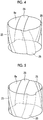
- the refrigerant guide grooves 25 are disposed near the positions of 12 o'clock, 3 o'clock, 6 o'clock, 9 o'clock in a dial of a timepiece (refer to Fig. 3 ), each inner opening portion 25a (a right end in Fig. 2 ) communicates with the internal space S1 of the housing 2, and the outer opening portion 25b (a left end in Fig. 2 ) communicates with a seal space S2 between the sub bearing 7 and the lip seal 9.
- each of the refrigerant guide grooves 25 is formed in an inclined groove shape having a predetermined inclination angle ⁇ , for example, a spiral groove shape in the center axis C direction of the drive shaft 5 by CNC processing or the like.
- a magnitude of the inclination angle ⁇ is set to be approximately 10° to 30° in the center axis C when viewed from a side.
- the inclination angle ⁇ of the refrigerant guide groove 25 is set such that an opening range of the inner opening portion 25a and an opening range of the outer opening portion 25b do not overlap with each other.
- the inclination angle ⁇ is set to approximately 50° at the maximum.
- the refrigerant guide groove 25 is formed in a spiral shape, and the spiral direction from the inner opening portion 25a toward the outer opening portion 25b is matched with a rotational direction R of the drive shaft 5. That is, as shown in Fig. 3 , if a rotation direction R of the drive shaft 5 is a counterclockwise direction when viewed from a rear portion side of the drive shaft 5, the refrigerant guide groove 25 is formed such that the spiral direction thereof becomes the counterclockwise direction.
- each refrigerant guide groove 25 is formed such that an interior angle ⁇ (an angle on an outer peripheral side of the bearing press-fitting portion 8a) at an intersection between the inner peripheral surface of the bearing press-fitting portion 8a and an inner peripheral surface of the refrigerant guide groove 25 is an obtuse angle of 90° or more.
- the interior angle ⁇ is approximately 120°.
- a ratio of a total groove width of the refrigerant guide groove 25 with respect to a circumference of the bearing press-fitting portion 8a is approximately 30% to 70%, preferably approximately 40% to 60%.
- the scroll compression mechanism 4 sucks the refrigerant gas to generate a negative pressure in the internal space S1 of the housing 2, the refrigerant gas is introduced from the suction port 3 into the internal space S1 by the negative pressure, the refrigerant gas becomes a compression refrigerant gas compressed by the scroll compression mechanism 4, and the compression refrigerant gas is discharged from the discharge port formed in the housing 2 so as to be supplied to a demand such as a condenser.
- the refrigerant gas flows from the internal space S1 to the seal space S2 via the refrigerant guide groove 25 inside the housing 2, and thus, the sub bearing 7 and the lip seal 9 are lubricated by mist or droplets of the lubricant contained in the refrigerant gas.
- the lubricant supplied for lubricating lubricates the rolling members 7c while passing through a portion between the outer ring member 7a of the sub bearing 7 and the inner ring member 7b, and thereafter, the lubricant is discharged to the internal space S1.
- the refrigerant guide groove 25 is formed to have the predetermined inclination angle ⁇ with respect to the center axis C direction of the drive shaft 5. Accordingly, after the outer ring member 7a of the sub bearing 7 press-fitted inside the bearing press-fitting portion 8a is press-fitted by shrinkage fitting, cooling fitting, or the like, when the outer ring member 7a spreads radially outward, a linear deformation of the outer ring member 7a over the entire length in the center axis C direction of the drive shaft 5 is prevented at a predetermined angular position on an outer peripheral surface of the outer ring member.
- a shape of the deformation portion is not a groove shape parallel in the axial direction of the drive shaft 5 and the shape of the deformation portion is a groove shape inclined in the axial direction. Accordingly, the rolling members 7c rolling inside the outer ring member 7a do not repeatedly fall into the inside of a deformation groove or do not repeatedly ride over the deformation groove simultaneously over the entire width. In addition, a radial clearance of the sub bearing 7 is not easily decreased.
- the refrigerant guide groove 25 When viewed in the axial direction of the drive shaft 5, the refrigerant guide groove 25 is formed such that an opening range of the inner opening portion 25a and an opening range of the outer opening portion 25b do not overlap with each other (refer to Figs. 2 and 3 ). Accordingly, even when the outer ring member 7a of the sub bearing 7 press-fitted to the bearing press-fitting portion 8a is deformed so as to bulge inside the refrigerant guide groove 25, a portion parallel in the axial direction of the drive shaft 5 does not occur within a range of the deformed shape. Therefore, it is possible to reliably prevent the rolling members 7c from falling into the inside of the deformation groove or riding over the deformation groove simultaneously over the entire width, and it is possible to prevent the decrease in the performance of the sub bearing 7.
- the refrigerant guide groove 25 is a spiral groove, and it is possible to easily form the refrigerant guide groove 25 by CNC processing.
- the spiral direction is matched with the rotational direction R of the drive shaft 5, and thus, a flow of the refrigerant gas orbited in the housing 2 by the rotation of the drive shaft 5 is easily taken into the refrigerant guide groove 25, and thus, it is possible to increase the lubrication performance of the sub bearing 7 and the lip seal 9.
- the interior angle ⁇ at the intersection between the inner peripheral surface of the bearing press-fitting portion 8a and the inner peripheral surface of the refrigerant guide groove 25 is an obtuse angle, and thus, a sharp edge due to the formation of the refrigerant guide groove 25 does not occur in the inner peripheral surface of the bearing press-fitting portion 8a. For this reason, the deformation of the outer ring member 7a of the sub bearing 7 press-fitted to the bearing press-fitting portion 8a becomes gentle and the rolling of the rolling member 7c becomes smooth. Accordingly, it is possible to more effectively prevent the decrease in the performance of the sub bearing 7.
- a ratio of the total groove width of the refrigerant guide groove 25 with respect to the circumference of the bearing press-fitting portion 8a is set to 30% to 70%, preferably approximately 40 to 60%. Accordingly, the groove width of the refrigerant guide groove 25 is widened as much as possible while the press fitting strength of the sub bearing 7 is secured, amounts of the refrigerant gas and the lubricant flowing through the refrigerant guide groove 25 are secured, and thus, it is possible to increase the lubrication performance of the sub bearing 7 and the lip seal 9.
- the open type scroll compressor 1 of the present embodiment it is possible to form the refrigerant guide groove 25 on the inner peripheral surface of the bearing press-fitting portion 8a to which the sub bearing 7 is press-fitted without decreasing performance of the sub bearing 7 and to increase the lubrication performance of the sub bearing 7 and the lip seal 9.
- a basic internal structure of the open type scroll compressor 1 and positional relationships of components do not necessarily need to be the same as those shown in the present embodiment.
- another type refrigerant compression mechanism such as a rotary type compression mechanism, a vane type compression mechanism, or a swash plate type compression mechanism may be adopted.
- the shape of the refrigerant guide groove 25 is not necessarily the shape of the above-described embodiment, and other shapes are conceivable as long as it has the predetermined inclination angle ⁇ with respect to the center axis C of the drive shaft 5.
- the spiral directions of the plurality of refrigerant guide grooves 25 may be alternately reversed, or the refrigerant guide groove 25 may be formed in a loop shape shown in Fig. 6 , a wavy line shape, a mesh shape, or the like.
- any shape may be adopted as long as the refrigerant guide groove 25 is inclined with respect to the center axis C, the one end of the refrigerant guide groove 25 communicates with the internal space S1 of the housing 2, and the other end thereof communicates with the seal space S2.
Landscapes
- Engineering & Computer Science (AREA)
- Mechanical Engineering (AREA)
- General Engineering & Computer Science (AREA)
- Compressor (AREA)
- Applications Or Details Of Rotary Compressors (AREA)
- Rolling Contact Bearings (AREA)
Applications Claiming Priority (2)
| Application Number | Priority Date | Filing Date | Title |
|---|---|---|---|
| JP2016156635A JP6758989B2 (ja) | 2016-08-09 | 2016-08-09 | 開放型冷媒圧縮機 |
| PCT/JP2017/028130 WO2018030245A1 (ja) | 2016-08-09 | 2017-08-02 | 開放型冷媒圧縮機 |
Publications (2)
| Publication Number | Publication Date |
|---|---|
| EP3450754A1 true EP3450754A1 (de) | 2019-03-06 |
| EP3450754A4 EP3450754A4 (de) | 2019-04-10 |
Family
ID=61162914
Family Applications (1)
| Application Number | Title | Priority Date | Filing Date |
|---|---|---|---|
| EP17839316.1A Withdrawn EP3450754A4 (de) | 2016-08-09 | 2017-08-02 | Offener kältemittelverdichter |
Country Status (3)
| Country | Link |
|---|---|
| EP (1) | EP3450754A4 (de) |
| JP (1) | JP6758989B2 (de) |
| WO (1) | WO2018030245A1 (de) |
Cited By (1)
| Publication number | Priority date | Publication date | Assignee | Title |
|---|---|---|---|---|
| US12378963B2 (en) * | 2022-06-06 | 2025-08-05 | Kabushiki Kaisha Toyota Jidoshokki | Motor-driven scroll electric compressor |
Families Citing this family (1)
| Publication number | Priority date | Publication date | Assignee | Title |
|---|---|---|---|---|
| DE102021126248A1 (de) * | 2021-10-11 | 2023-04-13 | Hanon Systems | Kältemittelverdichter |
Family Cites Families (5)
| Publication number | Priority date | Publication date | Assignee | Title |
|---|---|---|---|---|
| JPH1061550A (ja) * | 1996-08-27 | 1998-03-03 | Toyota Autom Loom Works Ltd | 圧縮機 |
| JP3041592B2 (ja) * | 1997-06-05 | 2000-05-15 | 株式会社ゼクセル | 横置き型スクロールコンプレッサ |
| JP4292539B2 (ja) | 2003-07-02 | 2009-07-08 | 株式会社ヴァレオサーマルシステムズ | 圧縮機 |
| WO2014064919A1 (ja) * | 2012-10-23 | 2014-05-01 | パナソニック株式会社 | ロータリ圧縮機 |
| JP6498405B2 (ja) * | 2014-09-24 | 2019-04-10 | 株式会社ヴァレオジャパン | 圧縮機 |
-
2016
- 2016-08-09 JP JP2016156635A patent/JP6758989B2/ja active Active
-
2017
- 2017-08-02 WO PCT/JP2017/028130 patent/WO2018030245A1/ja not_active Ceased
- 2017-08-02 EP EP17839316.1A patent/EP3450754A4/de not_active Withdrawn
Cited By (1)
| Publication number | Priority date | Publication date | Assignee | Title |
|---|---|---|---|---|
| US12378963B2 (en) * | 2022-06-06 | 2025-08-05 | Kabushiki Kaisha Toyota Jidoshokki | Motor-driven scroll electric compressor |
Also Published As
| Publication number | Publication date |
|---|---|
| EP3450754A4 (de) | 2019-04-10 |
| JP2018025135A (ja) | 2018-02-15 |
| JP6758989B2 (ja) | 2020-09-23 |
| WO2018030245A1 (ja) | 2018-02-15 |
Similar Documents
| Publication | Publication Date | Title |
|---|---|---|
| US10801495B2 (en) | Oil flow through the bearings of a scroll compressor | |
| US6439867B1 (en) | Scroll compressor having a clearance for the oldham coupling | |
| KR102619911B1 (ko) | 압축기 | |
| CN213981182U (zh) | 动涡旋组件及包括其的涡旋压缩机 | |
| EP3418569B1 (de) | Offener kältemittelverdichter | |
| KR20220082087A (ko) | 동시 회전 스크롤 압축기 | |
| JPWO2004001242A1 (ja) | プーリ支持用複列玉軸受 | |
| EP3276173A1 (de) | Kältemittelwellendichtung und mit der kältemittelwellendichtung ausgestatteter, offener kältemittelverdichter | |
| JP6554926B2 (ja) | スクロール圧縮機 | |
| JPH07145785A (ja) | トロコイド型冷媒圧縮機 | |
| US6179591B1 (en) | Conical hub bearing for scroll machine | |
| CN108930649B (zh) | 具有油管理系统的压缩机 | |
| JP6758989B2 (ja) | 開放型冷媒圧縮機 | |
| CN111089057A (zh) | 旋转机械的供油机构以及旋转机械 | |
| US7186098B2 (en) | Eccentric pump and method for operation of said pump | |
| US11566624B2 (en) | Compressor having lubrication system | |
| JP7325975B2 (ja) | 開放型圧縮機 | |
| EP3947974B1 (de) | Kompressor mit ölzuweisungselement | |
| US20210239113A1 (en) | Compressor Bearing | |
| JP2008291658A (ja) | スクロール圧縮機 | |
| CN220791497U (zh) | 涡旋压缩机以及制冷设备 | |
| CN116292276B (zh) | 压缩机构、涡旋式压缩机和制冷设备 | |
| JP2020143639A (ja) | 圧縮機及び輸送用冷凍機 | |
| JP2019056336A (ja) | スクロール型流体機械 | |
| JP5285339B2 (ja) | スクロール圧縮機 |
Legal Events
| Date | Code | Title | Description |
|---|---|---|---|
| STAA | Information on the status of an ep patent application or granted ep patent |
Free format text: STATUS: THE INTERNATIONAL PUBLICATION HAS BEEN MADE |
|
| PUAI | Public reference made under article 153(3) epc to a published international application that has entered the european phase |
Free format text: ORIGINAL CODE: 0009012 |
|
| STAA | Information on the status of an ep patent application or granted ep patent |
Free format text: STATUS: REQUEST FOR EXAMINATION WAS MADE |
|
| 17P | Request for examination filed |
Effective date: 20181129 |
|
| AK | Designated contracting states |
Kind code of ref document: A1 Designated state(s): AL AT BE BG CH CY CZ DE DK EE ES FI FR GB GR HR HU IE IS IT LI LT LU LV MC MK MT NL NO PL PT RO RS SE SI SK SM TR |
|
| AX | Request for extension of the european patent |
Extension state: BA ME |
|
| A4 | Supplementary search report drawn up and despatched |
Effective date: 20190313 |
|
| RIC1 | Information provided on ipc code assigned before grant |
Ipc: F04B 53/18 20060101ALI20190306BHEP Ipc: F04B 27/10 20060101ALI20190306BHEP Ipc: F04B 39/02 20060101ALI20190306BHEP Ipc: F04B 27/08 20060101ALI20190306BHEP Ipc: F04B 39/00 20060101AFI20190306BHEP Ipc: F04B 1/14 20060101ALI20190306BHEP Ipc: F04C 27/00 20060101ALI20190306BHEP Ipc: F04C 29/02 20060101ALI20190306BHEP Ipc: F04B 1/20 20060101ALI20190306BHEP |
|
| DAV | Request for validation of the european patent (deleted) | ||
| DAX | Request for extension of the european patent (deleted) | ||
| STAA | Information on the status of an ep patent application or granted ep patent |
Free format text: STATUS: THE APPLICATION IS DEEMED TO BE WITHDRAWN |
|
| 18D | Application deemed to be withdrawn |
Effective date: 20191009 |