EP3450848B1 - Procédé pour commander un appareil de combustion et un dispositif de commande - Google Patents
Procédé pour commander un appareil de combustion et un dispositif de commande Download PDFInfo
- Publication number
- EP3450848B1 EP3450848B1 EP17189064.3A EP17189064A EP3450848B1 EP 3450848 B1 EP3450848 B1 EP 3450848B1 EP 17189064 A EP17189064 A EP 17189064A EP 3450848 B1 EP3450848 B1 EP 3450848B1
- Authority
- EP
- European Patent Office
- Prior art keywords
- signal
- time
- combustion
- determining
- time series
- Prior art date
- Legal status (The legal status is an assumption and is not a legal conclusion. Google has not performed a legal analysis and makes no representation as to the accuracy of the status listed.)
- Active
Links
Images

Classifications
-
- F—MECHANICAL ENGINEERING; LIGHTING; HEATING; WEAPONS; BLASTING
- F02—COMBUSTION ENGINES; HOT-GAS OR COMBUSTION-PRODUCT ENGINE PLANTS
- F02D—CONTROLLING COMBUSTION ENGINES
- F02D41/00—Electrical control of supply of combustible mixture or its constituents
- F02D41/02—Circuit arrangements for generating control signals
- F02D41/14—Introducing closed-loop corrections
- F02D41/1401—Introducing closed-loop corrections characterised by the control or regulation method
- F02D41/1402—Adaptive control
-
- F—MECHANICAL ENGINEERING; LIGHTING; HEATING; WEAPONS; BLASTING
- F23—COMBUSTION APPARATUS; COMBUSTION PROCESSES
- F23N—REGULATING OR CONTROLLING COMBUSTION
- F23N5/00—Systems for controlling combustion
- F23N5/20—Systems for controlling combustion with a time program acting through electrical means, e.g. using time-delay relays
- F23N5/203—Systems for controlling combustion with a time program acting through electrical means, e.g. using time-delay relays using electronic means
-
- F—MECHANICAL ENGINEERING; LIGHTING; HEATING; WEAPONS; BLASTING
- F23—COMBUSTION APPARATUS; COMBUSTION PROCESSES
- F23N—REGULATING OR CONTROLLING COMBUSTION
- F23N5/00—Systems for controlling combustion
- F23N5/02—Systems for controlling combustion using devices responsive to thermal changes or to thermal expansion of a medium
- F23N5/08—Systems for controlling combustion using devices responsive to thermal changes or to thermal expansion of a medium using light-sensitive elements
-
- F—MECHANICAL ENGINEERING; LIGHTING; HEATING; WEAPONS; BLASTING
- F23—COMBUSTION APPARATUS; COMBUSTION PROCESSES
- F23N—REGULATING OR CONTROLLING COMBUSTION
- F23N5/00—Systems for controlling combustion
- F23N5/16—Systems for controlling combustion using noise-sensitive detectors
-
- F—MECHANICAL ENGINEERING; LIGHTING; HEATING; WEAPONS; BLASTING
- F23—COMBUSTION APPARATUS; COMBUSTION PROCESSES
- F23N—REGULATING OR CONTROLLING COMBUSTION
- F23N5/00—Systems for controlling combustion
- F23N5/24—Preventing development of abnormal or undesired conditions, i.e. safety arrangements
- F23N5/242—Preventing development of abnormal or undesired conditions, i.e. safety arrangements using electronic means
-
- F—MECHANICAL ENGINEERING; LIGHTING; HEATING; WEAPONS; BLASTING
- F02—COMBUSTION ENGINES; HOT-GAS OR COMBUSTION-PRODUCT ENGINE PLANTS
- F02D—CONTROLLING COMBUSTION ENGINES
- F02D41/00—Electrical control of supply of combustible mixture or its constituents
- F02D41/02—Circuit arrangements for generating control signals
- F02D41/14—Introducing closed-loop corrections
- F02D41/1401—Introducing closed-loop corrections characterised by the control or regulation method
- F02D2041/1413—Controller structures or design
- F02D2041/1426—Controller structures or design taking into account control stability
-
- F—MECHANICAL ENGINEERING; LIGHTING; HEATING; WEAPONS; BLASTING
- F02—COMBUSTION ENGINES; HOT-GAS OR COMBUSTION-PRODUCT ENGINE PLANTS
- F02D—CONTROLLING COMBUSTION ENGINES
- F02D41/00—Electrical control of supply of combustible mixture or its constituents
- F02D41/02—Circuit arrangements for generating control signals
- F02D41/14—Introducing closed-loop corrections
- F02D41/1401—Introducing closed-loop corrections characterised by the control or regulation method
- F02D2041/1413—Controller structures or design
- F02D2041/143—Controller structures or design the control loop including a non-linear model or compensator
-
- F—MECHANICAL ENGINEERING; LIGHTING; HEATING; WEAPONS; BLASTING
- F23—COMBUSTION APPARATUS; COMBUSTION PROCESSES
- F23N—REGULATING OR CONTROLLING COMBUSTION
- F23N2223/00—Signal processing; Details thereof
- F23N2223/06—Sampling
-
- F—MECHANICAL ENGINEERING; LIGHTING; HEATING; WEAPONS; BLASTING
- F23—COMBUSTION APPARATUS; COMBUSTION PROCESSES
- F23N—REGULATING OR CONTROLLING COMBUSTION
- F23N2223/00—Signal processing; Details thereof
- F23N2223/10—Correlation
-
- F—MECHANICAL ENGINEERING; LIGHTING; HEATING; WEAPONS; BLASTING
- F23—COMBUSTION APPARATUS; COMBUSTION PROCESSES
- F23N—REGULATING OR CONTROLLING COMBUSTION
- F23N2225/00—Measuring
- F23N2225/04—Measuring pressure
-
- F—MECHANICAL ENGINEERING; LIGHTING; HEATING; WEAPONS; BLASTING
- F23—COMBUSTION APPARATUS; COMBUSTION PROCESSES
- F23N—REGULATING OR CONTROLLING COMBUSTION
- F23N2225/00—Measuring
- F23N2225/08—Measuring temperature
-
- F—MECHANICAL ENGINEERING; LIGHTING; HEATING; WEAPONS; BLASTING
- F23—COMBUSTION APPARATUS; COMBUSTION PROCESSES
- F23N—REGULATING OR CONTROLLING COMBUSTION
- F23N2241/00—Applications
- F23N2241/20—Gas turbines
Definitions
- Embodiments of the present invention relate to methods and control devices for physical and chemical apparatuses in which undesired oscillations may emerge spontaneously due to a feedback coupling, in particular to methods and control devices for a combustion apparatus.
- thermoacoustic coupling may occur in apparatuses (systems) such as gas turbine engines, furnaces, boilers, rocket engines, and afterburners that are driven by confined combustion.
- Thermoacoustic coupling may lead to a self-excited instability, (also known as combustion instability, rumble, and reheat buzz), which appears spontaneously in the form of large amplitude pressure and heat release rate oscillations.
- the instability may be hazardous for the apparatus.
- thermoacoustic instabilities it is often desirable to suppress the thermoacoustic instabilities.
- Previously used control attempts (implicitly) assumed that the thermoacoustic instabilities correspond to limit cycle oscillations, possibly with harmonics. Therefore, the fact that the thermoacoustic system can undergo bifurcations to more complex nonlinear states, such as chaos is not taken into account. In fact, it is even possible that at onset of the instability when the system has just crossed the stability boundary, thermoacoustic oscillations correspond to a chaotic state. Previous methods will fail outright in such a scenario.
- WO 85/03761 A1 discloses a method for controlling a combustion apparatus comprising a combustion state in which a temperature related to the combustion state reflects a chaotic behaviour, the method comprising measuring the temperature and carrying out a cyclic measurement of the temperature, determining a time dependent periodically variable sequencing signal using a frequency of a desired periodic combustion state of the combustion apparatus, combining the signals for determining a control signal, and using the control signal to influence the combustion apparatus by applying the control signal to a valve.
- the method includes measuring the parameter and determining a time series of the parameter.
- a variable time delay is changed, the time series is shifted by the variable time delay for determining a time-shifted signal, and a difference between the time-shifted signal and the time series is formed for determining a time dependent first signal until a norm of the difference between the time-shifted signal and the time series is lowest.
- a time dependent second signal different to the first signal is determined. Determining the time dependent second signal includes at least one of using a frequency of a desired periodic combustion state of the combustion apparatus, and shifting the time series by a set time delay.
- the first signal and the second signal are combined for determining a control signal.
- the control signal is used to influence the combustion apparatus.
- the difference between the time-shifted signal and the time series is also referred to as (time dependent) difference signal.
- combustion state in which the parameter related to the combustion state reflects a chaotic behavior is also referred to as chaotic combustion state and chaotic state of combustion, respectively.
- the term "chaotic state” as used in this specification intends to describe a state of a system or apparatus exhibiting an aperiodic long-term behaviour with sensitive dependence on initial conditions.
- the term "aperiodic long-term behaviour” intends to describe that in the asymptotic dynamics the system or apparatus does not correspond to a fixed-point, a periodic orbit or a quasi-periodic behaviour.
- the system or apparatus may be (describable as) a non-linear deterministic system or apparatus, i.e. a system or apparatus in which the chaotic behaviour is not due to noisy or random forces, but rather due to the nonlinearity present in the system or apparatus, in particular a nonlinearity in the feedback coupling mechanism associated with thermoacoustic instability in the system or apparatus.
- sensitive dependence on initial conditions intends to describe that nearby initial conditions separate exponentially fast while the system or apparatus evolves in time.
- the method allows transferring the combustion apparatus from the chaotic combustion state into a periodic combustion state, and subsequently into a periodic state with a dominant frequency (of the parameter) shifted to the frequency of the desired oscillating state and/or a periodic state with reduced amplitude of oscillations compared to the initial state. Accordingly, hazardous instabilities of the combustion apparatus such as high mechanical loading can reliably be dampened or even suppressed. Further, other undesired effects that may occur in the chaotic state such as deterioration of exhaust values and exceeding of desired exhaust values, respectively, e.g. increased nitrogen oxide(s) (NO x ), may be avoided.
- NO x nitrogen oxide(s)
- the first signal is effective to drive the combustion apparatus from a chaotic combustion state into a periodic combustion state.
- Using a desired main frequency of the desired periodic combustion state for determining the second signal and, thus, the control signal of the combustion apparatus, allows driving the combustion state towards, more typically into the desired combustion state. Further, a damping of the amplitude of the oscillation of the parameter may be achieved.
- the set time delay ( ⁇ set ) determines the shift in the dominant frequency of the periodic combustion state.
- Whether an open-loop control based on the desired main frequency or a feed-back control using a set time delay ( ⁇ set ) is more efficient to drive the apparatus into the desired periodic combustion state may depend on the details of the apparatus.
- variable time delay ( ⁇ art ) for the first signal S 1 and the set time delay ( ⁇ set ) for the second signal S 2 will typically be of the order of the time-period of the acoustic resonance frequency of the apparatus.
- the set time delay ( ⁇ set ) may be determined based on mechanical, geometrical, chemical and/or thermodynamic properties of the combustion apparatus. For example, the set time delay may be determined based on the acoustic resonance frequency of the combustion apparatus.
- the parameter may be any variable or observable that participates in the chaotic behaviour of the thermoacoustic oscillations.
- thermoacoustic oscillations intends to describe fluctuations and/or oscillations in a medium such as a gas which are due to a feedback interaction between an acoustic field in the medium, and temporal fluctuations in the heat release rate from combustion (or from a flame).
- the term “thermoacoustic oscillations” shall embrace oscillations in a flame (and associated quantities such as the unsteady heat release rate from the flame), and in an acoustic field within an apparatus at least partly enclosing the flame, typically within a combustion chamber of the apparatus, that emerge spontaneously due to a constructive feedback interaction between the flame and the acoustic field.
- the parameter may be a pressure in the apparatus, a temperature in the apparatus, a density in the apparatus, a radiation power of the combustion (typically a chemiluminescence from the flame) or a parameter related to one or more of the pressure, the temperature, the density and the radiation power.
- the parameter is the pressure.
- the pressure in the apparatus can reliably be measured with high temporal resolution.
- the measured values of the parameter are typically high-pass filtered. Accordingly, a (long-term) drift of the parameter is eliminated.
- the norm of the difference signal may be determined as an integral or a sum of (all) absolute amplitude values of the difference signal, e.g. as sum absolute pressure values.
- a root mean square value of the amplitude values of the difference signal may be determined as norm of the difference signal.
- variable time delay is typically varied starting from a value close the inverse of the dominant frequency in the oscillations until the norm of the difference signal reaches a minimum value, typically a global minimum value.
- the amplitude of the first signal is small, typically close to zero if the apparatus is in a periodic state.
- the proposed controlling does not require analyzing the state of the apparatus and/or switching on and off the first signal.
- determining the time dependent first signal includes determining a difference between a first subset of the time series and a second subset of the time series, wherein the variable time delay between the first second subset and the second subset is determined so that so that a norm of the difference signal determined as difference between the first subset and the second subset is lowest.
- Combining the first signal and the second signal is typically achieved by adding the first signal and the second signal or by forming a weighted sum of the first signal and the second signal.
- Using the control signal may include feeding the input signal to an actuator coupled with the combustion apparatus.
- Using the control signal may also include converting the control signal to an input signal for the actuator and feeding the input signal to the actuator.
- the input signal may be a time dependent voltage.
- control signal or the input signal may be saturated prior to feeding to the actuator.
- Converting and/or saturating the control signal may also already be achieved during combining the first signal and the second signal using an appropriate function (F).
- the actuator is typically configured to convert the input signal, which is in the following also referred to as primary control signal into a secondary control signal suitable to influence the combustion apparatus.
- the primary control signal and the secondary control signal may be used to modulate a fuel-oxidant ratio, e.g. a fuel-air ratio, of fuel and oxidant used in the combustion apparatus for combustion.
- a fuel-oxidant ratio e.g. a fuel-air ratio
- Modulating the fuel-oxidant ratio may be achieved with little additional expense and has been found to be efficient for transferring the combustion apparatus from the chaotic combustion state into a non-chaotic combustion state.
- control signal or the saturated control signal may be converted into an acoustic signal, and the acoustic signal may be applied to the combustion apparatus.
- the method is performed in a cyclic manner and/or a continuously.
- the time series may be analyzed to determine a characteristic of a current combustion state, to change an input parameter of the function (F), e.g. increase a gain or weight of first signal if the current combustion state is still chaotic, and/or to change the set time delay.
- the characteristic may be a measure of non-periodicity, a distance from a bifurcation or the like.
- the characteristic may also be a fluctuation characteristic, in particular a measure for the amplitude oscillations such as a root-mean-square value (rms-value) of the measured values of the parameter or a measure of statistical dispersion of the measured values of the parameter such as the standard deviation.
- the fluctuation characteristic may be used to decide if the controlling is to be switched on.
- the control device includes a sensor for measuring a parameter related to a combustion state of a combustion apparatus, a controller coupled with the sensor, and an actuator coupled with the controller.
- the controller is configured to receive measured values of the parameter from the sensor and to determine a time series from the measured values of the parameter, to change a variable time delay, to shift the time series by the variable time delay for determining a time-shifted signal, and form a difference between the time-shifted signal and the time series for determining a time dependent first signal, until a norm of the difference between the time-shifted signal and the time series is lowest, to determine a time dependent second signal different to the first signal, wherein the second signal is determined based on a frequency of a desired oscillating state of the combustion apparatus and/or wherein determining the second signal comprises shifting the time series by a set time delay, and to outputting a function (F) of the first signal and the second signal as a primary control signal.
- the actuator is configured to convert the primary control signal into a secondary control signal suitable
- the control device is configured to vary the variable time delay, determine (a corresponding time-shifted signal and) a corresponding difference signal until the norm of the difference signal is lowest and reaches a minimum value, respectively, to determine the time dependent first signal.
- control device is also referred to as controller.
- control device is configured to perform any of the methods described herein.
- the controller may include an observer unit configured to determine a characteristic of a current state of the combustion apparatus using the time series of the parameter.
- the observer unit may further be configured to change an input parameter of the function (F) and/or to change the set time delay.
- the sensor is typically a pressure sensor, a temperature sensor or a light sensor.
- the sensor may provide the measured values of the parameter as respective voltage values.
- the actuator may be an acoustic actuator, an electromagnetically driven membrane, a valve, for example a fast-response valve, or a pump.
- a controlled system includes a chamber, typically combustion chamber, and the control device coupled with the chamber.
- the controlled system forms a jet engine, a gas turbine engine, a furnace, a boiler, rocket engine, or an afterburner.
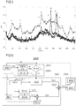
- Figure 1 shows a block diagram of the controlled apparatus 150.
- the controlled apparatus or system 150 consists of a combustion apparatus 50 and a control device 100 coupled with the combustion apparatus 50.
- combustion apparatus 50 is also referred to as combustor 50.
- a sensor 110 of the control device 100 is coupled with the combustor 50 to measure a parameter p related to a combustion state of the combustion apparatus 50 at different times t, for example pressure fluctuations.
- the sensor 110 is further coupled with a controller 120 of the device 100 so that the controller 120 can receive measured values p 1 (t) of the parameter p.
- the controller 120 may receive one measured values, typically several measured values p 1 per control cycle or a set of measured values p 1 per control cycle.
- the controller 120 determines time series S 0 (t) of the measured values p 1 (t) of the parameter p. This may include appending the measured value(s) p 1 (t) as or to an end of a storage structure such as an array, and an optional subsequent high-pass filtering.
- the controller 120 determines a primary control signal S(t) that is fed to an actuator 130 of the control device 100.
- the actuator 130 is connected with the controller 120 and coupled with the combustor 50.
- the actuator 130 converts the primary control signal S(t) into a secondary control signal p 2 (t) that is used to influence the combustion apparatus 50 in such a way that a chaotic combustion state of the combustion apparatus 50 is left and/or that the combustion apparatus 50 reaches a desired (non-chaotic) combustion state.
- a fuel-oxidant ratio of the combustion apparatus 50 may be modulated using the secondary control signal p 2 (t).
- the primary control signal S(t) is determined as function F of a first signal S 1 (t) and a second signal S 2 (t), typically as sum or weighted sum of the signals S 1 (t) and S 2 (t).
- the first signal S 1 (t) is determined by the controller 120 as follows.
- variable time delay ⁇ var may be initialized with a small value.
- the variable time delay ⁇ var may be initialized with a value close to a time-period which corresponds to a frequency of a dominant peak in the spectrum of the parameter.
- a time-shifted signal S ⁇ (t) is determined.
- variable time delay ⁇ var is changed and the processes for determining the difference signal may be repeated using the variable time delay ⁇ var .
- variable time delay ⁇ var and determining the difference signal S ⁇ (t, ⁇ var ) are repeated until the norm of the difference signal S ⁇ (t, ⁇ var ) reaches a smallest value.
- the finally determined difference signal S ⁇ is used as the first signal S 1 .
- the second signal S 2 (t) is determined by the controller 120 based on the frequency of a desired periodic state of the combustion apparatus 50.
- the second signal S 2 (t) is an open-loop control signal S OL (t).
- the second signal S 2 (t) is based on the time series S 0 (t) and a set time delay ⁇ set .
- the second signal S 2 (t) may be determined as delayed time series S 0 (t- ⁇ set ) or as a superposition S OL (t) + S 0 (t- ⁇ set ) or weighted superposition.
- the controller 120 is a two-stage controller that outputs a function F(S 1 (t), S 2 (t) ⁇ a k ⁇ ) as control signal S(t).
- the gains may be changed in time to achieve the desired combustion state. For example, a 2 may be set to 0 as long as the ⁇ var optimization is performed.
- a first of the two stages 121, 122 of the controller 120 is a feed-back control stage 121 and determines the first signal S 1 (t).
- a second of the two stages 121, 122 of the controller 120 determines the second signal S 2 (t).
- the second stage 122 may be (may operate as) a combined control stage (b 1 ⁇ 0, b 2 ⁇ 0).
- the controller 120 may also output a function G(S 0 (t), ⁇ a k , b i ⁇ , ⁇ set ) as control signal S(t) as illustrated in Fig. 2 .
- the set time delay ⁇ set may be modified till the combustion apparatus 50 reaches a desired combustion state with a desired frequency.
- control device 100 may have an observer unit 115 for determining a characteristic of a current state of the combustion apparatus 50 using the measured values p 1 (t) or the time series S 0 (t) (indicted by the dashed-dotted arrow).
- the observer unit 115 may change the function parameters ⁇ a k , b i ⁇ , ⁇ set explained above with respect to Fig. 2 .
- the observer unit 115 may increase the weight a 1 if the characteristic indicates that the current state is still chaotic.
- the observer unit 115 may decide to activate the controlling only (e.g. by assigning non-zero values to the weights a 1 and/or a 2 ) if desired, e.g. if a fluctuation characteristic is above a respective threshold.
- the observer unit 115 may be configured to deactivate the controlling or part thereof based on the characteristic(s).
- the observer unit 115 may also be an integral part of the controller 120.
- Figure 3 illustrates a flow diagram of a method 1000 that may be performed by the control device 100 explained above with respect to figures 1, 2 .
- a parameter (p) which is related to the combustion state such as a pressure in a combustion chamber or a (fluidically) connected upstream or downstream duct such as an exhaust pipe, for example a sound pressure, a temperature in the combustion chamber or the upstream or downstream duct, a temperature of a flame, and a radiation power of the flame is measured to obtain measured values (p 1 ) and therefrom a time series S 0 (t) of the parameter (p).
- control signal S(t) is used to influence the combustion apparatus 50.
- control signal S(t) may be fed to a suitable actuator such as an electromagnetically driven membrane or a valve of the combustion apparatus to modulate a fuel-oxidant ratio of the combustion apparatus.
- a suitable actuator such as an electromagnetically driven membrane or a valve of the combustion apparatus to modulate a fuel-oxidant ratio of the combustion apparatus.
- method 100 is typically performed in a cyclic/continuous manner.
- FIG 4 schematically illustrates an embodiment of a controlled combustion apparatus 450.
- the controlled combustion apparatus 450 is typically similar to the controlled apparatus 150 explained above with regard to figures 1, 2 , but described in more detail.
- the combustion apparatus 450 has two vertically orientated ducts 412, 414, typically steel ducts.
- the total length of the duct 412, 414 may be larger than 1 m and an inner diameter may be larger than about 10 cm.
- Reactants, fuel and air in the exemplary embodiment are injected at the bottom of the first (lower) duct 412 as indicated by the dashed arrows.
- the flow Prior to passing the upper duct 414, the flow may meet a perforated plate 413 employed as a holder to stabilize the flame in the upper duct 414.
- the plate 413 may e.g. have a hexagonal pattern of the holes.
- the flame remains stationary as the flame speed is equal to the speed of the unburnt flow at the flame location.
- perforated plates 413 as burners in a cross section of the reactant gas flow, heat is lost from the flame and the burning velocity decreases until it equals the unburnt mixture velocity. Therefore, a stable laminar flat flame confined in the upper duct 414 forming a combustion chamber is produced over a range of conditions.
- thermoacoustic coupling For example, a constructive feedback coupling between unsteady fluctuations in the flame and the acoustics of the combustion chamber (formed by upper duct 414) - plenum (formed by lower duct 412) assembly.
- a microphone 410 is attached to the lower duct 412 as sensor for measuring the pressure in the lower duct 412.
- the microphone may be attached to the upper duct 414.
- microphones may be used as sensors.
- measured pressure values p 1 (t) may be transferred from the microphone 410 to the two stages 421, 422 of the two-stage controller 421, 422.
- the controller stage 421 is implemented as feed-back control stage and configured to determine a first signal S 1 (t) as explained above with regard to Fig. 2 for the feed-back control stage 121.
- the controller stage 422 may have two subunits (sub-stages) 422a, 422b.
- the subunit 422a may determine the second signal S 2 (t) as open-loop control signal S OL (t), and subunit 422b may determine the second signal S 2 (t) a feedback signal S FB (t) as explained above with regard to Fig. 2 .
- the controller stage 422 may either provide the open-loop control signal S OL (t) (when the switch is in the switch setting shown in Fig. 4 ) or the feedback signal S FB (t) as second signal S 2 (t).
- each of the controller stages 421, 422 is connected with a corresponding compression driver 430 acting as actuators which are coupled with the lower duct 412.
- the actuators 430 are typically placed at identical axial distance from the flame in the duct 414.
- the compression drivers 430 typically include a respective electromagnetically driven membrane. Accordingly, the combustion process may be influenced sufficiently powerful and swift.
- the (voltage) signals S 1 (t), S 2 (t), and S(t), as described above may be used to generate a corresponding motion of the membrane.
- the motion of the membrane in turn generates pressure fluctuations that influence the thermoacoustic coupling between the acoustic field within the ducts 412, 414 and the flame.
- controller stages 421, 422 may be coupled with a common compression driver 430.
- Figure 5 shows frequency spectra a-c of pressure oscillations (psd) of the controlled combustor 450 shown in Figure 4 .
- Spectrum a corresponds to a chaotic combustion state of the combustor 450 with deactivated controller stages 421, 422 (uncontrolled combustion state).
- Spectrum a shows several pronounced broadband peaks, four of which are labelled as f 1 to f 4 .
- the combustor 450 is driven to and locked in the desired periodic state with main frequency f OL of 333 Hz.
- periodic combustion behavior can be locked to a desired frequency by changing the delay of the phase shift feedback (using sub stage 422b) or by changing the frequency of the open loop (using sub stage 422a). This may be particularly helpful for instance in combustors employing passive devices, which usually feature narrowband damping defined by their geometrical characteristics.
- the frequency of the instability can be adjusted to fall within the frequency band where the installed passive methods are effective.
- control device can be easily adjusted to follow (adapt to) any changes in the damper properties induced by changes in the operating conditions of the combustor.
- Figure 6 illustrates a flow diagram of a method 2000.
- the method 2000 is similar as the method 1000 explained above with regard to Fig. 3 , but explained in more detail.
- Method 2000 includes the blocks 2010, 2020 and 2030 which typically correspond to the respective blocks 1010, 1020 and 1030 of method 1000.
- the obtained time series S 0 (t) is initially analyzed in a block 2015 of method 2000.
- a value th representing amplitude fluctuations of the time series S 0 (t) (or the measured parameter values p 1 (t)) may be analyzed in a sub block 2015a of block 2015.
- control block 2020 may be activated. Otherwise, method 2000 may return from sub block 2015c of block 2015 to block 2010.
- sub block 2015c it may be decided in sub block 2015c to change one or more of the function parameters ⁇ a k , b i ⁇ , ⁇ set , f OL explained above, when the value th is above the threshold th1. Accordingly, current values of the function parameters ⁇ a k , b i ⁇ , ⁇ set , f OL may be updated in sub blocks 2016 and 2017 of block 2020, respectively.
- the second signal S 2 (t) may be combined with a first signal S 1 (t) determined in sub block 2021 of block 2020 as difference signal having a lowest (minimum) norm.
- the resulting primary control signal S(t) may be converted in a sub block 2031 of block 2030 into a secondary control signal p 2 (t) that is used in sub block 2032 of block 2030 to influence the combustion apparatus and the combustion state of the combustion apparatus, respectively .
- method 2000 may return to block 2010.
Landscapes
- Engineering & Computer Science (AREA)
- Chemical & Material Sciences (AREA)
- Combustion & Propulsion (AREA)
- Mechanical Engineering (AREA)
- General Engineering & Computer Science (AREA)
- Regulation And Control Of Combustion (AREA)
Claims (15)
- Procédé (1000, 2000) de commande d'un appareil de combustion (50) comprenant un état de combustion dans lequel un paramètre (p) lié à l'état de combustion reflète un comportement chaotique, le procédé comprenant :- la mesure du paramètre (p) et la détermination d'une série chronologique (So, P1) du paramètre (p) ;- la modification d'un retard temporel variable (τvar), le décalage de la série chronologique (S0) par le retard temporel variable (τvar), en vue de déterminer un signal décalé dans le temps (Sτ), et la formation d'une différence (Sτ - So) entre le signal décalé dans le temps (Sτ) et la série chronologique (S0), en vue de déterminer un premier signal dépendant du temps (S1) jusqu'à ce qu'une norme de la différence (Sτ - So) entre le signal décalé dans le temps (Sτ) et la série chronologique (S0) soit la plus faible ;- la détermination d'un second signal dépendant du temps (S2), différent du premier signal (S1), dans lequel la détermination du second signal dépendant du temps (S2) comprend au moins l'une des étapes d'utilisation d'une fréquence (fOL) d'un état de combustion périodique souhaité de l'appareil de combustion (50), et de décalage de la série chronologique (S0) par un retard de temps défini (τset) ;- la combinaison du premier signal (S1) et second signal (S2) en vue de déterminer un signal de commande (S, p2) ; et- l'utilisation du signal de commande (S, p2) pour influencer l'appareil de combustion (50).
- Procédé selon la revendication 1, dans lequel la combinaison du premier signal (S1) et du second signal (S2) comprend au moins l'une des étapes de détermination d'une fonction (F) du premier signal (S1) et du second signal (S2), de détermination d'une somme du premier signal (S1) et du second signal (S2), et de détermination d'une somme pondérée du premier signal (S1) et du second signal (S2).
- Procédé selon l'une quelconque des revendications précédentes, dans lequel la norme correspond à une somme de valeurs d'amplitude absolues de la différence (Sτ - So) entre le signal décalé dans le temps (Sτ) et la série chronologique (S0), et/ou dans lequel la norme correspond à une valeur quadratique moyenne des valeurs d'amplitude de la différence (Sτ - So) entre le signal décalé dans le temps (Sτ) et la série chronologique (S0), et/ou dans lequel le retard de temps variable (τvar) est modifié en commençant à partir d'une valeur proche d'un inverse d'une fréquence dominante de l'état de combustion périodique souhaité jusqu'à ce que la norme de la différence (Sτ - So) entre le signal décalé dans le temps (Sτ) et la série chronologique (S0) atteigne une valeur minimale.
- Procédé selon l'une quelconque des revendications précédentes, dans lequel le paramètre est une pression dans l'appareil, une température dans l'appareil, une densité dans l'appareil, une puissance de rayonnement de la combustion, ou un paramètre lié à au moins l'une parmi la pression, la température, la densité et la puissance de rayonnement.
- Procédé selon l'une quelconque des revendications précédentes, comprenant en outre l'analyse de la série chronologique (S0) en vue de déterminer une caractéristique d'un état en cours de la combustion, la modification d'un paramètre d'entrée ({a}) de la fonction (F), et/ou la modification du retard de temps défini (τset).
- Procédé selon l'une quelconque des revendications précédentes, dans lequel la détermination de la série chronologique (S0) comprend le filtrage passe-haut du paramètre mesuré (p1), et/ou dans lequel la détermination du premier signal dépendant du temps (S1) comprend la variation du retard de temps variable (τvar).
- Procédé selon l'une quelconque des revendications précédentes, dans lequel l'utilisation du signal de commande (S, p2) comprend au moins l'une des étapes ci-dessous :- la saturation du signal de commande (S) en vue de former un signal de commande saturé ;- l'injection du signal de commande (S) ou signal de commande saturé dans un actionneur (130, 430) couplé à l'appareil de combustion (50) ;- la modulation d'un rapport combustible-oxydant de l'appareil de combustion (50) ;- la modulation d'un débit de l'appareil de combustion (50) ; et au moins la première des deux étapes suivantes :- la conversion du signal de commande (S) ou signal de commande saturé en un signal acoustique ; et- l'application du signal acoustique à l'appareil de combustion (50).
- Procédé selon l'une quelconque des revendications précédentes, dans lequel le procédé est mis en œuvre de manière cyclique et/ou continue.
- Dispositif de commande (100), comprenant :- un capteur (110, 410) destiné à mesurer un paramètre (p) lié à un état de combustion d'un appareil de combustion (50) ;- un régulateur (120, 421, 422) connecté au capteur (110, 410) et configuré pour :- recevoir des valeurs mesurées (P1) du paramètre (p) en provenance du capteur (110) et déterminer une série chronologique (S0) des valeurs mesurées du paramètre (p) ;- modifier un retard de temps variable (τvar), décaler la série chronologique (S0), du retard de temps variable (τvar), en vue de déterminer un signal décalé dans le temps (Sτ), et former une différence (Sτ - So) entre le signal décalé dans le temps (Sτ) et la série chronologique (S0), en vue de déterminer un premier signal dépendant du temps (S1), jusqu'à ce qu'une norme de la différence (Sτ - So) entre le signal décalé dans le temps (Sτ) et la série chronologique (50) soit la plus faible ;- déterminer un second signal dépendant du temps (S2), différent du premier signal (S1), dans lequel le second signal (S2) est déterminé sur la base d'une fréquence (fOL) d'un état de combustion périodique souhaité de l'appareil de combustion (50), et/ou dans lequel la détermination du second signal (S2) comprend le décalage de la série chronologique (S0), par un retard de temps défini (τset) ; et- fournir en sortie une fonction (F) du premier signal (S1) et du second signal (S2), en tant qu'un signal de commande primaire (S) ; et- un actionneur (130, 430) connecté au régulateur (120) et configuré pour convertir le signal de commande primaire (S) en un signal de commande secondaire (p2) convenant pour influencer l'appareil de combustion (50).
- Dispositif selon la revendication 9, dans lequel le capteur (110, 410) est un capteur de pression, un capteur de température ou un capteur de lumière.
- Dispositif selon la revendication 9 ou 10, dans lequel l'actionneur (130, 430) est un actionneur acoustique, une membrane à entraînement électromagnétique, une soupape ou une pompe.
- Dispositif selon l'une quelconque des revendications 9 à 11, dans lequel le dispositif de commande (100, 421, 422) comprend une unité d'observation (115) configurée pour déterminer au moins l'un des éléments ci-dessous :- une caractéristique d'un état en cours de l'appareil de combustion, en utilisant la série chronologique (S0) ou les valeurs mesurées (p1) du paramètre (p) ;- l'utilisation de la caractéristique pour modifier un paramètre d'entrée ({a}) de la fonction (F) ; et- l'utilisation de la caractéristique pour modifier le retard de temps défini (τset).
- Dispositif selon l'une quelconque des revendications 9 à 12, dans lequel le dispositif de commande (100, 421, 422) est configuré pour mettre en œuvre le procédé selon l'une quelconque des revendications 1 à 8.
- Système commandé (150, 450) comprenant une chambre (412, 414) et le dispositif de commande (100) selon l'une quelconque des revendications 9 à 13, couplé à la chambre (412, 414).
- Système selon la revendication 14, dans lequel la chambre est une chambre de combustion (412, 414), et/ou dans lequel le système commandé est formé par, ou inclut au moins l'un parmi, un moteur à réaction, un moteur-fusée, un moteur à turbine à gaz, un four, une chaudière et un dispositif de post-combustion.
Priority Applications (4)
| Application Number | Priority Date | Filing Date | Title |
|---|---|---|---|
| EP17189064.3A EP3450848B1 (fr) | 2017-09-01 | 2017-09-01 | Procédé pour commander un appareil de combustion et un dispositif de commande |
| CN201880056685.8A CN111033125B (zh) | 2017-09-01 | 2018-08-21 | 用于控制燃烧设备的方法和控制装置 |
| US16/638,408 US11525417B2 (en) | 2017-09-01 | 2018-08-21 | Method for controlling a combustion apparatus and control device |
| PCT/EP2018/072484 WO2019042813A1 (fr) | 2017-09-01 | 2018-08-21 | Procédé de commande d'un appareil de combustion et dispositif de commande |
Applications Claiming Priority (1)
| Application Number | Priority Date | Filing Date | Title |
|---|---|---|---|
| EP17189064.3A EP3450848B1 (fr) | 2017-09-01 | 2017-09-01 | Procédé pour commander un appareil de combustion et un dispositif de commande |
Publications (2)
| Publication Number | Publication Date |
|---|---|
| EP3450848A1 EP3450848A1 (fr) | 2019-03-06 |
| EP3450848B1 true EP3450848B1 (fr) | 2021-01-06 |
Family
ID=59772472
Family Applications (1)
| Application Number | Title | Priority Date | Filing Date |
|---|---|---|---|
| EP17189064.3A Active EP3450848B1 (fr) | 2017-09-01 | 2017-09-01 | Procédé pour commander un appareil de combustion et un dispositif de commande |
Country Status (4)
| Country | Link |
|---|---|
| US (1) | US11525417B2 (fr) |
| EP (1) | EP3450848B1 (fr) |
| CN (1) | CN111033125B (fr) |
| WO (1) | WO2019042813A1 (fr) |
Families Citing this family (4)
| Publication number | Priority date | Publication date | Assignee | Title |
|---|---|---|---|---|
| EP3450848B1 (fr) | 2017-09-01 | 2021-01-06 | Technische Universität Berlin | Procédé pour commander un appareil de combustion et un dispositif de commande |
| CN112326730A (zh) * | 2020-10-21 | 2021-02-05 | 北京航空航天大学 | 一种采用多麦克风测量热释放率脉动的实验方法及装置 |
| PL4060232T3 (pl) * | 2021-03-16 | 2023-09-11 | Siemens Aktiengesellschaft | Wykrywanie mocy i regulacja współczynnika nadmiaru powietrza za pomocą czujników w komorze spalania |
| CN113654024A (zh) * | 2021-08-24 | 2021-11-16 | 北京天衡智联科技有限公司 | 一种蒸汽锅炉管道压力联动控制系统 |
Family Cites Families (13)
| Publication number | Priority date | Publication date | Assignee | Title |
|---|---|---|---|---|
| US4473906A (en) | 1980-12-05 | 1984-09-25 | Lord Corporation | Active acoustic attenuator |
| WO1985003761A1 (fr) * | 1984-02-22 | 1985-08-29 | Vulcan Australia Limited | Rechauffeurs a gaz et leur regulation |
| JPS61125521A (ja) | 1984-11-21 | 1986-06-13 | Rinnai Corp | 燃焼器の制御装置 |
| US7832211B2 (en) | 2002-12-02 | 2010-11-16 | Mitsubishi Heavy Industries, Ltd. | Gas turbine combustor and a gas turbine equipped therewith |
| DE10257244A1 (de) * | 2002-12-07 | 2004-07-15 | Alstom Technology Ltd | Verfahren und Vorrichtung zur Beeinflussung thermoakustischer Schwingungen in Verbrennungssystemen |
| DE502005002405D1 (de) | 2004-01-12 | 2008-02-14 | Siemens Vdo Automotive Ag | Regelungsverfahren und regelungseinrichtung für einen aktor |
| EP1762786A1 (fr) * | 2005-09-13 | 2007-03-14 | Siemens Aktiengesellschaft | Procédé et appareil pour réduire les vibrations thermo-accoustiques, en particulier dans une turbine |
| DE102008004229A1 (de) | 2008-01-14 | 2009-07-16 | GM Global Technology Operations, Inc., Detroit | System und Verfahren zur Steuerung der Verbrennungsphasen in einem Verbrennungsmotor |
| WO2015083186A2 (fr) * | 2013-12-04 | 2015-06-11 | Indian Institute Of Technology Madras | Système et procédé pour réguler les instabilités oscillatoires dans un dispositif |
| KR101667104B1 (ko) | 2014-07-17 | 2016-10-17 | 한국전력공사 | 연소 불안정 제어 방법 |
| JP2018178745A (ja) * | 2017-04-04 | 2018-11-15 | トヨタ自動車株式会社 | 内燃機関の制御装置 |
| EP3450848B1 (fr) | 2017-09-01 | 2021-01-06 | Technische Universität Berlin | Procédé pour commander un appareil de combustion et un dispositif de commande |
| CN112326730A (zh) | 2020-10-21 | 2021-02-05 | 北京航空航天大学 | 一种采用多麦克风测量热释放率脉动的实验方法及装置 |
-
2017
- 2017-09-01 EP EP17189064.3A patent/EP3450848B1/fr active Active
-
2018
- 2018-08-21 US US16/638,408 patent/US11525417B2/en active Active
- 2018-08-21 CN CN201880056685.8A patent/CN111033125B/zh active Active
- 2018-08-21 WO PCT/EP2018/072484 patent/WO2019042813A1/fr not_active Ceased
Non-Patent Citations (1)
| Title |
|---|
| None * |
Also Published As
| Publication number | Publication date |
|---|---|
| CN111033125B (zh) | 2021-12-31 |
| US20200200110A1 (en) | 2020-06-25 |
| EP3450848A1 (fr) | 2019-03-06 |
| US11525417B2 (en) | 2022-12-13 |
| CN111033125A (zh) | 2020-04-17 |
| WO2019042813A1 (fr) | 2019-03-07 |
Similar Documents
| Publication | Publication Date | Title |
|---|---|---|
| EP3450848B1 (fr) | Procédé pour commander un appareil de combustion et un dispositif de commande | |
| US5428951A (en) | Method and apparatus for active control of combustion devices | |
| Annaswamy et al. | Active control of combustion instability: Theory and practice | |
| Dowling et al. | Feedback control of combustion oscillations | |
| Peracchio et al. | Nonlinear heat-release/acoustic model for thermoacoustic instability in lean premixed combustors | |
| Bošković et al. | Stabilization of a solid propellant rocket instability by state feedback | |
| Neumeier | Experimental demonstration of active control of combustion instabilities using real-time modes observation and secondary fuel injection | |
| Zinn et al. | An overview of active control of combustion instabilities | |
| Evesque et al. | Self-tuning regulators for combustion oscillations | |
| Manoj et al. | Rijke tube: A nonlinear oscillator | |
| Bellows et al. | Nonlinear interactions between forced and self-excited acoustic oscillations in premixed combustor | |
| Xi et al. | Experimental study of transition to instability in a Rijke tube with axially distributed heat source | |
| EP3182008A1 (fr) | Amortisseur de helmholtz destiné à une turbine à gaz et une telle turbine avec ledit amortisseur | |
| CN111043623A (zh) | 一种基于电场影响火焰根部的闭环负反馈调节避免燃烧室产生共振的方法 | |
| US5361710A (en) | Method and apparatus for the active control of a compact waste incinerator | |
| Zhang et al. | Active control of multiple neural networks for oscillating combustion | |
| Schimek et al. | Amplitude-dependent flow field and flame response to axial and tangential velocity fluctuations | |
| Kabiraj et al. | A review on noise-induced dynamics of thermoacoustic systems | |
| Wei et al. | Dynamic compensation based adaptive control of thermo-acoustic instabilities in Rijke tube: An experimental validation | |
| Gutmark et al. | Closed-loop control in a flame and a dump combustor | |
| Kulkarni et al. | Non-normality and its consequences in active control of thermoacoustic instabilities | |
| Hathout | Thermoacoustic instability | |
| Auer et al. | Active instability control: feedback of combustion instabilities on the injection of gaseous fuel | |
| JPH11257646A (ja) | 液体燃料供給源と燃焼器とを有するシステム用の装置 | |
| Makeximu et al. | Desired dynamic equation based PID control for combustion vibration |
Legal Events
| Date | Code | Title | Description |
|---|---|---|---|
| PUAI | Public reference made under article 153(3) epc to a published international application that has entered the european phase |
Free format text: ORIGINAL CODE: 0009012 |
|
| STAA | Information on the status of an ep patent application or granted ep patent |
Free format text: STATUS: THE APPLICATION HAS BEEN PUBLISHED |
|
| AK | Designated contracting states |
Kind code of ref document: A1 Designated state(s): AL AT BE BG CH CY CZ DE DK EE ES FI FR GB GR HR HU IE IS IT LI LT LU LV MC MK MT NL NO PL PT RO RS SE SI SK SM TR |
|
| AX | Request for extension of the european patent |
Extension state: BA ME |
|
| STAA | Information on the status of an ep patent application or granted ep patent |
Free format text: STATUS: REQUEST FOR EXAMINATION WAS MADE |
|
| 17P | Request for examination filed |
Effective date: 20190902 |
|
| RBV | Designated contracting states (corrected) |
Designated state(s): AL AT BE BG CH CY CZ DE DK EE ES FI FR GB GR HR HU IE IS IT LI LT LU LV MC MK MT NL NO PL PT RO RS SE SI SK SM TR |
|
| STAA | Information on the status of an ep patent application or granted ep patent |
Free format text: STATUS: EXAMINATION IS IN PROGRESS |
|
| 17Q | First examination report despatched |
Effective date: 20200117 |
|
| GRAP | Despatch of communication of intention to grant a patent |
Free format text: ORIGINAL CODE: EPIDOSNIGR1 |
|
| STAA | Information on the status of an ep patent application or granted ep patent |
Free format text: STATUS: GRANT OF PATENT IS INTENDED |
|
| INTG | Intention to grant announced |
Effective date: 20200722 |
|
| GRAS | Grant fee paid |
Free format text: ORIGINAL CODE: EPIDOSNIGR3 |
|
| GRAA | (expected) grant |
Free format text: ORIGINAL CODE: 0009210 |
|
| STAA | Information on the status of an ep patent application or granted ep patent |
Free format text: STATUS: THE PATENT HAS BEEN GRANTED |
|
| RIN1 | Information on inventor provided before grant (corrected) |
Inventor name: SAURABH, ADITYA Inventor name: LIPIKA, KABIRAJ Inventor name: PASCHEREIT, CHRISTIAN OLIVER |
|
| AK | Designated contracting states |
Kind code of ref document: B1 Designated state(s): AL AT BE BG CH CY CZ DE DK EE ES FI FR GB GR HR HU IE IS IT LI LT LU LV MC MK MT NL NO PL PT RO RS SE SI SK SM TR |
|
| REG | Reference to a national code |
Ref country code: GB Ref legal event code: FG4D |
|
| REG | Reference to a national code |
Ref country code: AT Ref legal event code: REF Ref document number: 1352765 Country of ref document: AT Kind code of ref document: T Effective date: 20210115 Ref country code: CH Ref legal event code: EP |
|
| REG | Reference to a national code |
Ref country code: DE Ref legal event code: R096 Ref document number: 602017030807 Country of ref document: DE |
|
| REG | Reference to a national code |
Ref country code: IE Ref legal event code: FG4D |
|
| REG | Reference to a national code |
Ref country code: SE Ref legal event code: TRGR |
|
| REG | Reference to a national code |
Ref country code: NL Ref legal event code: MP Effective date: 20210106 |
|
| REG | Reference to a national code |
Ref country code: AT Ref legal event code: MK05 Ref document number: 1352765 Country of ref document: AT Kind code of ref document: T Effective date: 20210106 |
|
| REG | Reference to a national code |
Ref country code: NO Ref legal event code: T2 Effective date: 20210106 |
|
| REG | Reference to a national code |
Ref country code: LT Ref legal event code: MG9D |
|
| PG25 | Lapsed in a contracting state [announced via postgrant information from national office to epo] |
Ref country code: FI Free format text: LAPSE BECAUSE OF FAILURE TO SUBMIT A TRANSLATION OF THE DESCRIPTION OR TO PAY THE FEE WITHIN THE PRESCRIBED TIME-LIMIT Effective date: 20210106 Ref country code: HR Free format text: LAPSE BECAUSE OF FAILURE TO SUBMIT A TRANSLATION OF THE DESCRIPTION OR TO PAY THE FEE WITHIN THE PRESCRIBED TIME-LIMIT Effective date: 20210106 Ref country code: GR Free format text: LAPSE BECAUSE OF FAILURE TO SUBMIT A TRANSLATION OF THE DESCRIPTION OR TO PAY THE FEE WITHIN THE PRESCRIBED TIME-LIMIT Effective date: 20210407 Ref country code: PT Free format text: LAPSE BECAUSE OF FAILURE TO SUBMIT A TRANSLATION OF THE DESCRIPTION OR TO PAY THE FEE WITHIN THE PRESCRIBED TIME-LIMIT Effective date: 20210506 Ref country code: LT Free format text: LAPSE BECAUSE OF FAILURE TO SUBMIT A TRANSLATION OF THE DESCRIPTION OR TO PAY THE FEE WITHIN THE PRESCRIBED TIME-LIMIT Effective date: 20210106 Ref country code: BG Free format text: LAPSE BECAUSE OF FAILURE TO SUBMIT A TRANSLATION OF THE DESCRIPTION OR TO PAY THE FEE WITHIN THE PRESCRIBED TIME-LIMIT Effective date: 20210406 |
|
| PG25 | Lapsed in a contracting state [announced via postgrant information from national office to epo] |
Ref country code: AT Free format text: LAPSE BECAUSE OF FAILURE TO SUBMIT A TRANSLATION OF THE DESCRIPTION OR TO PAY THE FEE WITHIN THE PRESCRIBED TIME-LIMIT Effective date: 20210106 Ref country code: PL Free format text: LAPSE BECAUSE OF FAILURE TO SUBMIT A TRANSLATION OF THE DESCRIPTION OR TO PAY THE FEE WITHIN THE PRESCRIBED TIME-LIMIT Effective date: 20210106 Ref country code: LV Free format text: LAPSE BECAUSE OF FAILURE TO SUBMIT A TRANSLATION OF THE DESCRIPTION OR TO PAY THE FEE WITHIN THE PRESCRIBED TIME-LIMIT Effective date: 20210106 Ref country code: RS Free format text: LAPSE BECAUSE OF FAILURE TO SUBMIT A TRANSLATION OF THE DESCRIPTION OR TO PAY THE FEE WITHIN THE PRESCRIBED TIME-LIMIT Effective date: 20210106 |
|
| PG25 | Lapsed in a contracting state [announced via postgrant information from national office to epo] |
Ref country code: IS Free format text: LAPSE BECAUSE OF FAILURE TO SUBMIT A TRANSLATION OF THE DESCRIPTION OR TO PAY THE FEE WITHIN THE PRESCRIBED TIME-LIMIT Effective date: 20210506 |
|
| REG | Reference to a national code |
Ref country code: DE Ref legal event code: R097 Ref document number: 602017030807 Country of ref document: DE |
|
| PG25 | Lapsed in a contracting state [announced via postgrant information from national office to epo] |
Ref country code: EE Free format text: LAPSE BECAUSE OF FAILURE TO SUBMIT A TRANSLATION OF THE DESCRIPTION OR TO PAY THE FEE WITHIN THE PRESCRIBED TIME-LIMIT Effective date: 20210106 Ref country code: CZ Free format text: LAPSE BECAUSE OF FAILURE TO SUBMIT A TRANSLATION OF THE DESCRIPTION OR TO PAY THE FEE WITHIN THE PRESCRIBED TIME-LIMIT Effective date: 20210106 Ref country code: SM Free format text: LAPSE BECAUSE OF FAILURE TO SUBMIT A TRANSLATION OF THE DESCRIPTION OR TO PAY THE FEE WITHIN THE PRESCRIBED TIME-LIMIT Effective date: 20210106 |
|
| PLBE | No opposition filed within time limit |
Free format text: ORIGINAL CODE: 0009261 |
|
| STAA | Information on the status of an ep patent application or granted ep patent |
Free format text: STATUS: NO OPPOSITION FILED WITHIN TIME LIMIT |
|
| PG25 | Lapsed in a contracting state [announced via postgrant information from national office to epo] |
Ref country code: SK Free format text: LAPSE BECAUSE OF FAILURE TO SUBMIT A TRANSLATION OF THE DESCRIPTION OR TO PAY THE FEE WITHIN THE PRESCRIBED TIME-LIMIT Effective date: 20210106 Ref country code: RO Free format text: LAPSE BECAUSE OF FAILURE TO SUBMIT A TRANSLATION OF THE DESCRIPTION OR TO PAY THE FEE WITHIN THE PRESCRIBED TIME-LIMIT Effective date: 20210106 Ref country code: DK Free format text: LAPSE BECAUSE OF FAILURE TO SUBMIT A TRANSLATION OF THE DESCRIPTION OR TO PAY THE FEE WITHIN THE PRESCRIBED TIME-LIMIT Effective date: 20210106 |
|
| 26N | No opposition filed |
Effective date: 20211007 |
|
| PG25 | Lapsed in a contracting state [announced via postgrant information from national office to epo] |
Ref country code: AL Free format text: LAPSE BECAUSE OF FAILURE TO SUBMIT A TRANSLATION OF THE DESCRIPTION OR TO PAY THE FEE WITHIN THE PRESCRIBED TIME-LIMIT Effective date: 20210106 Ref country code: ES Free format text: LAPSE BECAUSE OF FAILURE TO SUBMIT A TRANSLATION OF THE DESCRIPTION OR TO PAY THE FEE WITHIN THE PRESCRIBED TIME-LIMIT Effective date: 20210106 |
|
| PG25 | Lapsed in a contracting state [announced via postgrant information from national office to epo] |
Ref country code: SI Free format text: LAPSE BECAUSE OF FAILURE TO SUBMIT A TRANSLATION OF THE DESCRIPTION OR TO PAY THE FEE WITHIN THE PRESCRIBED TIME-LIMIT Effective date: 20210106 |
|
| REG | Reference to a national code |
Ref country code: BE Ref legal event code: MM Effective date: 20210930 |
|
| PG25 | Lapsed in a contracting state [announced via postgrant information from national office to epo] |
Ref country code: IS Free format text: LAPSE BECAUSE OF FAILURE TO SUBMIT A TRANSLATION OF THE DESCRIPTION OR TO PAY THE FEE WITHIN THE PRESCRIBED TIME-LIMIT Effective date: 20210506 Ref country code: MC Free format text: LAPSE BECAUSE OF FAILURE TO SUBMIT A TRANSLATION OF THE DESCRIPTION OR TO PAY THE FEE WITHIN THE PRESCRIBED TIME-LIMIT Effective date: 20210106 |
|
| PG25 | Lapsed in a contracting state [announced via postgrant information from national office to epo] |
Ref country code: LU Free format text: LAPSE BECAUSE OF NON-PAYMENT OF DUE FEES Effective date: 20210901 Ref country code: IE Free format text: LAPSE BECAUSE OF NON-PAYMENT OF DUE FEES Effective date: 20210901 Ref country code: BE Free format text: LAPSE BECAUSE OF NON-PAYMENT OF DUE FEES Effective date: 20210930 |
|
| PG25 | Lapsed in a contracting state [announced via postgrant information from national office to epo] |
Ref country code: IT Free format text: LAPSE BECAUSE OF NON-PAYMENT OF DUE FEES Effective date: 20210901 |
|
| TPAB | Information related to observations by third parties deleted |
Free format text: ORIGINAL CODE: EPIDOSDTIPA |
|
| TPAC | Observations filed by third parties |
Free format text: ORIGINAL CODE: EPIDOSNTIPA |
|
| PG25 | Lapsed in a contracting state [announced via postgrant information from national office to epo] |
Ref country code: CY Free format text: LAPSE BECAUSE OF FAILURE TO SUBMIT A TRANSLATION OF THE DESCRIPTION OR TO PAY THE FEE WITHIN THE PRESCRIBED TIME-LIMIT Effective date: 20210106 Ref country code: NL Free format text: LAPSE BECAUSE OF NON-PAYMENT OF DUE FEES Effective date: 20210206 |
|
| PG25 | Lapsed in a contracting state [announced via postgrant information from national office to epo] |
Ref country code: HU Free format text: LAPSE BECAUSE OF FAILURE TO SUBMIT A TRANSLATION OF THE DESCRIPTION OR TO PAY THE FEE WITHIN THE PRESCRIBED TIME-LIMIT; INVALID AB INITIO Effective date: 20170901 |
|
| PG25 | Lapsed in a contracting state [announced via postgrant information from national office to epo] |
Ref country code: MK Free format text: LAPSE BECAUSE OF FAILURE TO SUBMIT A TRANSLATION OF THE DESCRIPTION OR TO PAY THE FEE WITHIN THE PRESCRIBED TIME-LIMIT Effective date: 20210106 |
|
| PG25 | Lapsed in a contracting state [announced via postgrant information from national office to epo] |
Ref country code: MT Free format text: LAPSE BECAUSE OF FAILURE TO SUBMIT A TRANSLATION OF THE DESCRIPTION OR TO PAY THE FEE WITHIN THE PRESCRIBED TIME-LIMIT Effective date: 20210106 |
|
| PGFP | Annual fee paid to national office [announced via postgrant information from national office to epo] |
Ref country code: DE Payment date: 20240919 Year of fee payment: 8 |
|
| PGFP | Annual fee paid to national office [announced via postgrant information from national office to epo] |
Ref country code: GB Payment date: 20240923 Year of fee payment: 8 |
|
| PGFP | Annual fee paid to national office [announced via postgrant information from national office to epo] |
Ref country code: FR Payment date: 20240924 Year of fee payment: 8 |
|
| PGFP | Annual fee paid to national office [announced via postgrant information from national office to epo] |
Ref country code: NO Payment date: 20240919 Year of fee payment: 8 Ref country code: SE Payment date: 20240923 Year of fee payment: 8 |
|
| PGFP | Annual fee paid to national office [announced via postgrant information from national office to epo] |
Ref country code: CH Payment date: 20241001 Year of fee payment: 8 |
|
| PG25 | Lapsed in a contracting state [announced via postgrant information from national office to epo] |
Ref country code: TR Free format text: LAPSE BECAUSE OF FAILURE TO SUBMIT A TRANSLATION OF THE DESCRIPTION OR TO PAY THE FEE WITHIN THE PRESCRIBED TIME-LIMIT Effective date: 20210106 |