EP3450905B1 - Messmaschine von nichtkarthesischen hexapod- oder hexapodähnlichen koordinaten - Google Patents
Messmaschine von nichtkarthesischen hexapod- oder hexapodähnlichen koordinaten Download PDFInfo
- Publication number
- EP3450905B1 EP3450905B1 EP17189077.5A EP17189077A EP3450905B1 EP 3450905 B1 EP3450905 B1 EP 3450905B1 EP 17189077 A EP17189077 A EP 17189077A EP 3450905 B1 EP3450905 B1 EP 3450905B1
- Authority
- EP
- European Patent Office
- Prior art keywords
- hexapod
- air
- cmm
- linear
- linear member
- Prior art date
- Legal status (The legal status is an assumption and is not a legal conclusion. Google has not performed a legal analysis and makes no representation as to the accuracy of the status listed.)
- Active
Links
Images




Classifications
-
- G—PHYSICS
- G01—MEASURING; TESTING
- G01B—MEASURING LENGTH, THICKNESS OR SIMILAR LINEAR DIMENSIONS; MEASURING ANGLES; MEASURING AREAS; MEASURING IRREGULARITIES OF SURFACES OR CONTOURS
- G01B21/00—Measuring arrangements or details thereof, where the measuring technique is not covered by the other groups of this subclass, unspecified or not relevant
-
- G—PHYSICS
- G01—MEASURING; TESTING
- G01B—MEASURING LENGTH, THICKNESS OR SIMILAR LINEAR DIMENSIONS; MEASURING ANGLES; MEASURING AREAS; MEASURING IRREGULARITIES OF SURFACES OR CONTOURS
- G01B5/00—Measuring arrangements characterised by the use of mechanical techniques
- G01B5/0002—Arrangements for supporting, fixing or guiding the measuring instrument or the object to be measured
- G01B5/0004—Supports
-
- G—PHYSICS
- G01—MEASURING; TESTING
- G01B—MEASURING LENGTH, THICKNESS OR SIMILAR LINEAR DIMENSIONS; MEASURING ANGLES; MEASURING AREAS; MEASURING IRREGULARITIES OF SURFACES OR CONTOURS
- G01B21/00—Measuring arrangements or details thereof, where the measuring technique is not covered by the other groups of this subclass, unspecified or not relevant
- G01B21/02—Measuring arrangements or details thereof, where the measuring technique is not covered by the other groups of this subclass, unspecified or not relevant for measuring length, width, or thickness
- G01B21/04—Measuring arrangements or details thereof, where the measuring technique is not covered by the other groups of this subclass, unspecified or not relevant for measuring length, width, or thickness by measuring coordinates of points
- G01B21/047—Accessories, e.g. for positioning, for tool-setting, for measuring probes
-
- G—PHYSICS
- G01—MEASURING; TESTING
- G01B—MEASURING LENGTH, THICKNESS OR SIMILAR LINEAR DIMENSIONS; MEASURING ANGLES; MEASURING AREAS; MEASURING IRREGULARITIES OF SURFACES OR CONTOURS
- G01B5/00—Measuring arrangements characterised by the use of mechanical techniques
- G01B5/004—Measuring arrangements characterised by the use of mechanical techniques for measuring coordinates of points
- G01B5/008—Measuring arrangements characterised by the use of mechanical techniques for measuring coordinates of points using coordinate measuring machines
Definitions
- the present invention relates to a Coordinate Measuring Machine (short CMM), in particular to a non-Cartesian Coordinate Measuring Machine (short NCCMM), wherein the functionally of this NCCMM is based on the principals of a hexapod structure, so that this Coordinate Measuring Machine is also called a hexapod CMM or a hexapod-like CMM.
- short CMM Coordinate Measuring Machine
- NCCMM non-Cartesian Coordinate Measuring Machine
- a hexapod CMM 10 The basic principal of a hexapod CMM 10 is presented on the bases of figure 1 .
- a hexapod CMM comprises a base structure 12 and a moveable structure 14 that are spaced apart by usually six telescopically extendable legs 16 (16a, 16b, 16c, 16d, 16e, 16f).
- the six telescopically extendable legs 16 (16a, 16b, 16c, 16d, 16e, 16f) are connected with their bottom ends to the base structure 12 using spherical joints 28 (28a, 28b, 28c, 28d, 28e, 28f).
- spherical joints 26 (26a, 26b, 26c, 26d, 26e, 26f).
- the spherical joints 26, 28 may be build as a ball joint, cardan joint or Hooke's joint, a flexural mechanism etc. well known by skilled persons.
- spherical joint is used as a general term for all those different joints allowing more or less arbitrary spherical rotation like: flexural mechanism, ball joints, cardan joints or Hooke's joints etc.).
- each extendable leg 16 is connected with its bottom end pairwise - namely 16a and 16b, 16c and 16d, 16e and 16f - with the adjacent extendable leg arranged at its one side, while the same extendable leg 16 is connected with its top end pairwise with the adjacent extendable leg of its other side - namely 16a and 16c, 16b and 16f, 16d and 16e -, so that the leg pairs form triangles with a rim of the base structure 12 and a rim of the moveable structure 14, respectively.
- Each telescopically extendable leg 16 comprises a drive means (motor and according mechanism, not shown), at least one sliding linear member 23 configured to slide along at least one stationary linear member 22 -the stationary linear member is often a hollow member accommodating the sliding member - and an according number of linear encoders 24 measuring the relative displacement of the at least one linear sliding member 23 relative to the stationary linear member 22 or relative to further linear sliding members (not shown).
- the length of each extendable leg 16 is controlled by an associated controller (not shown) for each leg or a central controller 38 using the information generated by the linear encoder(s) 24 to control the drive means in a servo loop.
- a program for controlling the movement of the legs 16 and by this the movement of the movable structure 14 may be stored in an internal memory 39 connected to the controller.
- the controller 38 further includes an analysing unit 32.
- the linear members 22, 23 of a leg 16 - also called leg-members - are made of a light material as aluminum, an aluminum alloy or plastics and in particular reinforced plastics comprising glass-fibres and/or carbon fibres.
- the movable structure 14 is usually made of a light but rigid material like the materials used for the leg-members, wherein the base structure 12, when it forms the bottom of the CMM to stand on, is often made of a more heavy material.
- an object 20 - also called a workpiece 20 - that is to be measured is placed on the base structure 12 of the hexapod CMM 10.
- Optionally fixation means 18, like brackets, can be provided in order to fix the workpiece 20 to the base structure 12.
- Altering the length of the various legs 16 allows the moveable structure 14, and hence a probe 30 fixed to the movable structure 14, to be moved relative to the base structure 12 and the workpiece 20 with 6 degrees of freedom (6DOF): 3 degrees of freedom regarding the lateral movement in the Cartesian-directions x, y, z and further 3 degrees of freedom regarding rotational movement around these Cartesian x-, y-, z-axis resulting in yawing, rolling, pitching.
- 6 degrees of freedom 6 degrees of freedom
- the form of an workpiece 20 placed on the base structure 12 of such a hexapod CMM 10 can easily be measured by the probe 30 mounted to the movable structure 14 of said hexapod CMM 10 from different perspectives.
- the moveable structure 14 and the extendable legs 16 - including the movement options of the legs 16 - define a working volume, the probe is moveable within said working volume.
- Results of the measurement of the probe 30 might be analysed in an internal control unit 38 and/or using an external control unit 36; wherein at least one of the controllers 38, 36 comprises an analysing unit 32.
- Data transfer within the CMM i.e.
- FIG. 2 A slightly different example of a Non Cartesian CMM 10' is shown in figure 2 .
- the NCCMM 10' shown in figure 2 is based on the principals of the hexapod CMM described above for fig. 1 . It is therefore called a hexapod-like CMM.
- a bottom platform 9 carries the workpiece 20 and supports piles 8, which piles 8 (adumbrated by dashed lines) support the base structure 12 on their top in a fixed position.
- the movable structure 14 is arranged hanging from this top arranged base structure 12 on three (instead of six) extendable legs 16 (16a, 16b, 16c).
- a probe 30 is fixed to the hanging movable platform 14 directed towards the bottom platform 9 carrying the workpiece 20.
- the movable structure 14 with the probe 30 is movable relative to the bottom platform 9 and to the base structure 12, respectively, with 6 degrees of freedom (seeabove), by extension and contraction of the legs 16, so that the workpiece 20 on the bottom platform 9 can be measured from all sides and from all perspectives.
- the telescopically extendable legs are formed as struts, most often in the form of an outer hollow tubular portion and at least one inner tubular portion, wherein each of the at least one inner tubular portions is slidable within the next outer hollow tubular portion.
- hollow elements instead of hollow elements as leg-members it is also possible to design the struts and leg-members, respectively, in form of i.e. tongue-and-groove, dovetail guide, u-sections or a u-section and a t-section slidable against each other or sections with other cross sections suitable for sliding relative to each other.
- the drive means may comprise any arrangement that introduces relative axial motion between a first leg-member and a second leg-member or even further leg-members and thus allows extension and contraction of the leg.
- the drive means may be hydraulic, or may comprise a screw jack, an direct drive mechanism or an electronic drive arrangement including e.g. a friction drive like it is described in US 5,604,593 .
- Each of the six extendable legs of the hexapod CMM of US 5,604,593 comprises in each case a tubular housing and a tubular ram member, which tubular ram member slides telescopically within the tubular housing driven by means of a friction drive.
- This friction drive comprises a motorised drive roller, and an opposing reaction roller, both of the rollers engage with the tubular ram member such that rotation of the motorised drive roller 54 extends the ram member from the tubular housing or retracts the ram member into the tubular housing.
- US 5,604,593 does not only try to avoid the disadvantages of common spherical joints but also suggests to reduce the influence of load and vibrations on the measurement.
- US 5,604,593 suggests to measure the relative displacement of the moveable structure to the base structure not any more by a linear encoder integrated in the extendable legs, but to measure it by six tracking interferometers each comprising a light source, a retro reflector and a detection unit for detecting the light reflected by the retro reflector.
- the light sources and the detection unit are placed together at the base side, wherein the retro reflector is mounted linear opposite at the movable structure.
- the interferometers are mounted either within the hollow rams or beside the spherical bearings connecting the legs to the base structure and to the moveable structure.
- Each tracking interferometer tracks and measures the distance to its corresponding retro reflector and a computer control is enabled to calculate from the six linear measurements the obtained position and orientation of the moveable structure including position and orientation of the probe fixed to the moveable structure.
- US 7,841,097 B2 suggests a different strategy to eliminate the negative influences of load impacts, deflection by weight, inertia effects and vibrations during movement on the preciseness of the measurements.
- the hexapod NCCMM of US 7,841,097 B2 discloses a hexapod CMM with a hexapod double structure: a load bearing hexapod structure including motor driven struts and a load bearing base structure and a load bearing movable platform. Further, and parallel to this load bearing hexapod structure a hexapod metrology structure is provided coupled with the load bearing structure.
- the metrology hexapod structure comprises a metrology base structure, a metrology moveable platform carrying the probe and extendable legs, expansion and contraction of these legs are operated by the motor driven struts of the load bearing parallel hexapod structure.
- the metrology moveable platform is connected to the parallel load bearing moveable platform
- the metrology base structure is connected to load bearing base structure
- the metrology legs are connected to the load bearing, motor driven struts in a way that no or very little load and no or very little vibrations are transmitted from the load bearing structure to the metrology structure.
- the metrology extendable legs are actuated in their extension and contraction by the load bearing extendable legs of the load bearing hexapod structure.
- the metrology extendable legs are provided with linear encoders in order to measure the relative displacement of their extendable and contractionable parts, respectively, without any influence of load deflection or motor/movement vibrations, which is carried solely by the load bearing legs.
- load deflection or motor/movement vibrations which is carried solely by the load bearing legs.
- the hexapod double structure is very expensive.
- US 5,509,939 A relates to a NCCMM having a base plate and a movable tracing head connected to the baseplate by 6 telescopically extendable legs.
- US 6,607,157 B1 describes various possibilities to connect two elements by a joint, so that they are movable against each other, like pivot joints, ball bearing, cone bearing, cylindrical linear joints etc.
- inaccuracies and transfer of vibration document US 6,607,157 B1 teaches to use air or another fluid in those joints for cushioning the elements against each other.
- measuring speed as well as precision of the measurement of an hexapod CMM or hexapod-like CMM should be increased.
- service efforts service time, service interval and service expenses
- operation noise of an hexapod CMM or an hexapod-like CMM based on the principals of a hexapod can be reduced by using extendable legs with an air cushioning mechanism.
- a hexapod CMM or hexapod-like CMM which is based on the principals of a hexapod as described above, has a base structure and a movable structure connected to each other by at least three telescopically extendable legs.
- the telescopically extendable legs are connected to the base structure and to the movable structure, respectively by spherical joints.
- each of the telescopically extendable legs comprises at least a linear first member and a linear second member having countersliding surfaces and are configured to slide linearly in relation to each other. It should be mentioned here that sliding might also include linear motion using linear roller bearings and other techniques known by a skilled person.
- a drive mechanism is endued driving the relative linear motion of the at least two linear members of each leg and a controller designed to control the relative movement of the first linear member and the second linear member of each leg in a servo loop.
- Each of the telescopically extendable legs has an air cushioning mechanism comprising at least an air supply system connected to at least one source of compressed air and having at least one air escape.
- the air escape is arranged in such a way that compressed air escaping the air escape flows into a gap between the countersliding surfaces of the at least two linear members of the leg cushioning the two linear members against each other.
- the air cushioning mechanism reduces transfer of bending errors caused by load or force misbalances and transfer of vibration from the base structure to the movable structure and thereby increases repeatability of measurement results and measurement precision. It reduces bearing noise and allows a higher moving speed. It thereby allows scanning measurement instead of point by point measurement.
- the hexapod CMM or hexapod-like CMM might be integrated in a production line producing measurement "in-line" with the production.
- controller is an internal controller and/or an external controller, wherein the controller may include an analysing unit.
- the gap between the countersliding surfaces of the at least two linear members either exists independent of the flow of the compressed air of the cushioning mechanism or the countersliding surface of at least one of the at least two linear members belongs to a bearing element which bearing element is spring mounted in such a way that the air flow escaping the air escape creates a gap between the countersliding surfaces of the at least two linear members by compressing the spring of the spring mounted bearing element.
- the spring of the spring mounted bearing element might be realised by a classic pressure spring, coil spring, disc spring or sheet spring or by the use of a permanent magnet and/or an electromagnet or a pneumatic cylinder or hydraulic cylinder.
- the cushioning mechanism comprises at least one sensor for measuring air pressure and/or air flow rate. It further comprises at least one pressure regulator for a manual control of the air flow. Thereby the sensor for measuring air pressure or may be integrated in the pressure regulator. In addition or alternatively to the one pressure regulator at least one controllable valve is provided in the air cushioning mechanism and the controller is designed to control the at least one controllable valve in a servo loop dependent on the detected air pressure and/or air flow rate.
- the source of compressed air is at least one out of the group comprising: an air compressor, a compressed air vessel, an air supply system of a facility.
- the air compressor and the air vessel may be part of the hexapod CMM or hexapod-like CMM or bay be separate from the hexapod CMM or hexapod-like CMM like the air supply system of the facility, wherein the facility is typically a laboratory.
- the air supply system of the air cushioning mechanism comprises at least one air supply channel (70) and or at least one air hose (71) and further an air distribution system (72, 73, 74).
- the air distribution system (72, 73, 74) of the air supply system comprises at least the one air escape mentioned above but further may comprise an air ring channel and an air supply pipe.
- the linear members of the leg have a guiding structure guiding the linear members relative to each other along their axial extension, i.e. the first linear member is a hollow member, designed to accommodate a body of the linear second member in such a way that it allows a relative, linear movement of the first linear member and the second linear member, whereby the cross-section of the hollow first linear member and the according body of the second linear member may be circular, oval, triangular or polygone.
- the leg-members may also be connected to each other such that they are dovetail guided slidable against each other or in form of a tongue-and-groove, or are designed in form of i.e. u-sections slidable against each other, or in form of a u-section and a bar slidable against each other, or as a u-section and a t-section meshing, or sections with other cross sections suitable for sliding relative to each other.
- the air cushioning mechanism comprises beside the at least one air escape leading the air flow into the gap between the two leg-members at least one air outlet.
- the air cushioning mechanism is based on an air flow.
- the air flow further increase measurement precision as less thermal effects occur because of the cooling effect of the air flow. Further abrasion particles are "washed" away by the air flow and humidity and dust from outside are prevented to enter or if it had entered it is dragged out as well.
- the air cushioning mechanism is endued with at least one controllable valve and a controller designed to control the at least one valve in a servo loop, so that an controlled air flow between the air escape and an air outlet is realisable.
- a controller designed to control the at least one valve in a servo loop, so that an controlled air flow between the air escape and an air outlet is realisable.
- groups of air escapes are connected with an controllable valve or even better each air escape is provided with an controllable vale.
- a further advantage might be achieved if one or more air pressure sensors and/or one or more air flow rate sensors are integrated in the air cushioning mechanism. Using those sensors allows for a detection of leakage and blockage within the air cushioning mechanism. Further the controller in such a case can control the controllable valve (s) in a servo loop dependent on the detected air pressure and/or air flow rate.
- the first linear member is a hollow member and the second linear member has a body accommodated slidably within the hollow first linear member.
- the hollow first linear member comprises bearing rings or a bearing sleeve for guiding the linear movement of the second linear member and its body, respectively.
- a plurality of air escapes are distributed along the inner surface of the bearing rings or the bearing sleeve of the first linear body.
- the air escapes are equally distributed, wherein equally distributed means either equally in axial rows and/or equally along the circumferential.
- the hollow first linear member comprises a surrounding wall, the inner surface of which forms the countersliding surface of the first linear member, and which surrounding wall guides the linear movement of the second linear member.
- a plurality of air escapes are distributed along the inner surface of the surrounding wall, wherein the distribution of the air escapes again is preferably equal in axial rows and/or along the circumferential.
- the at least one electro magnet and the at least one permanent magnet, respectively, are designed as single magnet, a plurality of magnets or a magnetic layer covering at least a part of the surface facing the gap.
- each leg is endued with a distance measurement unit for measuring the distance between the countersliding surfaces of the at least two linear members or between a surface of the first linear member and a surface of the second linear member facing each other in the gap.
- the surface of the first linear member is thereby is the inner surface of the surrounding wall, or the inner surface of at least one of the bearing rings or the inner surface of the bearing sleeve directed towards the second linear member.
- the distance measurement unit comprises at least two distance measurement sensors arranged at the same axial level in relation to the longitudinal axis of the leg and in an angle of 90° ⁇ 25° to each other and around the longitudinal axis of the leg. Based on the data derived by the distance measurement unit irregularities of the system can be detected, particularly relative tilting of the axis of the linear members of the leg and/or irregularities in the air flow of the air cushioning mechanism.
- the distance measurement unit comprises at least two distance measurement sensors at a first axial level in relation to the longitudinal axis of the leg and at least two further distance measurement sensors at a second axial level in relation to the longitudinal axis of the leg, wherein the two axial levels are arranged in axial distance to each other, and wherein each two distance measurement sensors of the same axial level are arranged in an angle of 90° ⁇ 25° to each other and around the longitudinal axis of the leg (15).
- a tilting even a relative bending of the linear members of the leg can be detected by a distance measurement unit like this.
- a less expensive alternative - enabling more or less only detection of a tilt - is the use of a tilt sensor.
- distance measurement sensors capacitive sensors, short distance optical sensors or IMUs (1dof up to 9 or even more dofs), tilt sensors, hall sensors, eddy current sensors etc. may be used.
- the distance measurement sensors are laser interferometers.
- load misbalances and/or force misbalances are detectable.
- the controller of the hexapod CMM or hexapod-like CMM is preferably designed to detect those irregularities, like load misbalances and/or force misbalances and/or leakages/blockages in the air cushioning mechanism.
- the controller - external or internal - is designed for detecting irregularities like load misbalances and/or force misbalances and/or leakages/blockages in the air cushioning mechanism based on the data measured by the at least one pressure sensor and/or the at least one air flow rate sensor and/or the distance measurement unit.
- controller is preferably designed for not only detecting but also correcting such irregularities by controlling the at least one valve per leg in a servo loop and/or it is designed for giving a warning output or to initiate an emergency stop if the measured irregularities increase over a predetermined threshold.
- the spherical joints are formed as air ball bearings with balls seated in ball bearing shells, wherein each of the balls slides on an air flow arranged between the ball and the bearing shell. This reduces further stick-slip-effects and the noise of the hexapod CMM or hexapod-like CMM during the measurement and increases further the measurement precision.
- the ball in the air ball bearing is hold within the bearing shell by a magnetic force.
- the magnetic force may be produced by a strong electro magnet or a strong permanent magnet.
- strong in the term “strong permanent magnet” that the magnetic force is chosen in relation to the forces, which assembly will be effective in the according joint.
- the magnetic force will be at any time be chosen at least strong enough to hold the ball in the bearing shell.
- the magnet may be a single magnet or a plurality of magnets or a magnetic layer covering the surface of the bearing shell.
- the second linear member is a hollow structure and a weight balance body is arranged within the hollow body of said hollow linear member.
- the second linear member is preferably arranged at the top of the hexapod CMM or hexapod-like CMM.
- the weight balance body by use of a mounting suspension is fixed to the top structure of the hexapod CMM or hexapod-like CMM, i.e. to the top arranged movable structure or the top arranged base structure, i.e. via the top spherical joint.
- the weight balance body is air buffered in the hollow leg-member, whereby the air buffer is created by an air flow loading the mounting suspension with a tension force.
- the length of the mounting suspension and the strength of the air flow are chosen dependent on the own weight and the predicted forces that will be effective in such a way that the balance point of the extended leg is shifted in an advantageous position, so that the risk of bending of the extended legs and its linear members respectively, is reduced.
- figure 1 presents an example of a Non Cartesian CMM 10 in form of a typical hexapod CMM with six extendable legs 16;
- figure 2 presents an example of a simplified form of a Non Cartesian CMM 10' based on the same principals as the hexapod CMM of fig 1 , but having only 3 extendable legs 16 and a hanging movable structure 14, so that this NCCMM is called a hexapod-like CMM.
- the present invention relates to hexapod CMM as well as to hexapod-like CMM and related NCCMM based on the principals of a hexapod (the latter ones should be included in the term "hexapod-like CMM").
- measuring speed as well as precision of the measurement of such a hexapod CMM and hexapod-like CMM can be increased, while service efforts (service time, service interval and service expenses) and operation noise of such an NCCMM 10, 10' can be reduced using extendable legs 15 with an air cushioning mechanism 1.
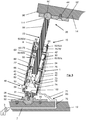
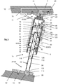
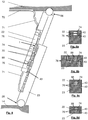
- Figures 3 to 9c each show an example of such an extendable leg 15 with an air cushioning mechanism 1, wherein figures 3 and 4 each presents a leg 15 joint with its bottom end to a supporting base structure 12 and joint with its top end to a movable structure 14, analogous to the structure of the NCCMM of figure 1 ; figures 5 , 6 and 8 each presents a leg 15 joint with its top end to a supporting base structure 12 in a hanging manner, and joint with its bottom end to a movable structure 14, which movable structure 14 accordingly hangs on the leg 15 (the base structure 12 might be supported by piles arranged on a base plate (not shown in figures 5 , 6 and 8 )) analogous to the structure of the NCCMM of figure 2 .
- the extendable leg 15 presented in figure 3 is connected with its bottom end to the base structure 12 by a spherical joint 28 and at its top end it is connected to the movable structure 14 by another spherical joint 26.
- Both of these spherical joints 26, 28 are in this example conventional ball bearings with a bearing ball 90, 90' spherically seated in a bearing shell - also called bearing seat - wherein part of the bearing shell is integrated in the base structure 12 and the movable structure 14, respectively, and part of the bearing shell is integrated in a screw 44 fixed housing 92, 92'.
- the spherical joints 26, 28 may also be Hooke's joints or other suitable spherical joints as known by a skilled person.
- the leg 15 presented in figure 3 comprises a first linear member 22 and a second linear member 23.
- the first linear member 22 is hollow with a surrounding wall 40, which in this embodiment is cylindrical and has a bottom 41 closing the cylinder at its bottom side.
- the bottom 41 is fixed to the ball 90 of the bottom ball bearing 28.
- the bottom 41 of the surrounding wall 40 is fixed by a screw 102 to the ball 90 but any other suitable fixation is also possible like welding etc., even a construction with an integrated ball at the bottom (hollow cylinder 40, bottom 41 and ball 90 are formed as one piece) is imaginable.
- the second linear member 23 has a body 84, which in the example of figure 3 is a massive body of a light weight material like an aluminum alloy or plastics, in particular reinforced plastics. It also can be made of a light weight structure like a honeycomb structure or the like or a hollow structure like in figures 4 to 6 .
- the hollow first linear member 22 is designed to accommodate the second linear member 23 such that it is linear movable within the first linear member 22 driven by a driving mechanism 48.
- a driving mechanism 48 for this purpose - in this example - three bearing rings 42, 42' are arranged inside the hollow first linear member 22 in axial distance to each other.
- bearing rings 42, 42' Dependent on the length of the linear members and the possible relative movement one, two, three or even more bearings rings are suitable. In general at least one bearing ring 42 is suitable, but two bearing rings 42 are advantageous.
- the bearing ring(s) 42 guide the movement of the second linear member 22 within the first linear member 22 in its/their approximate middle.
- the driving mechanism 48 in this example comprises a driving motor 50 arranged in the bottom part of the leg 15.
- the motor 50 drives a drive roller 58, wherein the drive roller 58 is arranged within the hollow first linear member 22 having its rotation axis perpendicular oriented to the longitudinal axis of the first linear member 22.
- the drive roller 58 drives a drive belt or cable 60.
- the cable 60 is seated on one hand on the drive roller 58 on the other hand on a idler pulley 64, which idler pulley 64 is arranged in an axial distance of the drive roller 58 and in this example in the top end region of the first linear member 22 of the leg 15; the rotation axis of the idler pulley 64 having the same orientation as the drive roller 58.
- the second linear member 23 comprises a body 84 and at least one gripper 62 protruding radially from said body 84.
- two grippers 62 are shown, but dependent on the distance between the drive roller 58 and the idler pulley 64 one, two or even more grippers might be suitable.
- the grippers 62 are arranged in an axial row so that the grippers 62 are enabled to grip the cable 60.
- the bearing rings 42 are wherever necessary endued with an according cable recess 66 for the free movement of the cable 60 and the grippers 62.
- the second linear member 23 is movable outwardly and inwardly in relation to the accommodating hollow first linear member 22 by driving the drive roller 58 forward and backward / clockwise and counter-clock wise using the motor 50 and by this driving the cable 60 - gripped by the grippers 62 of the second linear member 23 - up and down.
- the relative movement of the second linear member 23 to the first linear member 22 is measured by a linear encoder 24 and controlled as described for figures 1 and 2 by an according controller.
- the linear encoder 24 converts the encoded position into an analog or digital signal, which can be decoded into a position by a read out or motion controller.
- the linear encoder 24 may be based on i.e. optical technologies, magnetic technologies, inductive technologies, capacitive technologies, eddy current or interferometric technologies; it may be either incremental or absolute. When using interferometric technologies, the laser beam can be send within or aside the extendable leg 15.
- the air cushioning mechanism 1 comprises at least one air supply system 69 connected to at least one source of compressed air 2.
- the source of compressed air 2 may be an external source or may be part of the air supply system 69 and/or the hexapod CMM or hexapod-like CMM, respectively.
- an external source for compressed air 2 an house intern compressed air system might be used, like it exists in most laboratories.
- an internal source for compressed air 2 an air compressor or a compressed air vessel may figure, which might or might not be integrated in the hexapod or hexapod-like CMM.
- the air supply system 69 further comprises an air supply channel 70, 71, which air supply channel 70, 71 includes at least one air channel 70 and where appropriate an air hose 71. It further comprises an air distribution system 72, 73, 74.
- the air supply channel 70, 71 distributes compressed air from the source of compressed air 2 to air supply pipes 72.
- the air further flows through the air supply pipes 72 into ring channels 73 and further through air escapes 74 into the hollow first linear member 22.
- the ring channels 73 are each integrated in the bearing rings 42 and are each connected upstream to at least one of the supply pipes 72 and downstream to at least one of the air escapes 74.
- the air ring channels 73 also may be integrated in the wall 40 of the first linear member 22 (not shown).
- the air escapes 74 are arranged radially between each ring channel 73 and the inner surface of each ring bearing 42.
- a plurality of air escapes 74 are connected downstream to one ring channel 73 and are preferably equally distributed along the circumference.
- the flow rate is usually manually controllable by the use of air pressure regulators 3 in connection with sensors measuring the air pressure (not shown). Instead or additionally to the air pressure the air flow might be measured. However, the air flow can also be controlled by using one or more air valves 4 (see figure 4 ) which is/are controlled in a servo loop dependent on the measured air pressure and/or air flow rate. According sensors for measuring/detecting airflow and/or air pressure (not shown) are located at different places within the air cushioning mechanism 1 of the extendable leg 15.
- the measured air pressure (and/or measured air flow rate) might be used in order to detect a misbalance of forces and/or weight load in the NCCMM or in order to detect a leakage or blockage of the air supply system.
- the compressed air leaving the air escape 74 flows into a small gap 76 arranged between the bearing rings 42 and the body 84 of the second linear member 23.
- the gap 76 might be in the range of 10 micrometre to 1,5 millimetre.
- the air flow is ideally equal around the body 84 of second linear member 23 and holds the body 84 in the middle of the bearing rings 42.
- the compressed air escape the gap 76 and flows into the inner space of the hollow first linear member 22 from where it escapes via an air outlet 75 build by the uppermost gap 76' between the uppermost bearing ring 42' (situated at the free, open end of the hollow cylinder 40 of the first linear member 22) and the body 84 of the second linear member 23 as well as by the uppermost cable recess 66' in this uppermost bearing ring 42'.
- the air flow has a cooling effect, which might actively be used for temperature stabilizing in the whole NCCMM by control of air pressure/air flow rates.
- temperature gradients might be homogenized or temperature might be held constant for a certain time period, so that transient effects might be smoothed out and temperature influences on the measurement results can be reduced.
- operation speed of the NCCMM can be increased and scanning measurement operations can be realised instead of having a measurement point by point.
- the over all throughput can be increased and the NCCMM might even be integrated in a production line.
- a distance measurement unit 80 may be installed inside the hollow first linear member 22; which distance measurement unit 80 measures the distance between the inner surface of the surrounding wall 40 of the first linear member 22 and the body 84 of the second linear member 23.
- a bending of the leg 15 can be detected, which means that either the weight load and/or the effective forces in the NCCMM are not in balance and/or that there are imperfections of the air flow. Imperfections of the air flow means that the air flow does not hold the body 84 in the middle of the bearing rings 42, which might be the result of a leakage or blockage in the air supply system.
- the latter one can be verified by comparing the distance measurement results with the results of the air flow and/or the air pressure measurements in the system, which is done by the accordingly programmed control and analysing unit 38 of the system.
- the air flow may be controlled accordingly in an according servo loop or a warning or emergency stop may be realised.
- the distance measurement unit 82 in this embodiment is very precise as it comprises four distance sensors 82 in form of four laser interferometers 82a, 82b, 82c, 82d.
- a first set of two laser interferometers 82a, 82b are arranged in axial distance of a second set of two laser interferometers 82c, 82d.
- the two laser interferometer of this according level are arranged in an angle of about 90° ⁇ 25° to each other.
- Such phenomena might be countered with a selectively controlled air flow, in case the air supply system is provided with further servo controlled valves 4 (like in fig. 4 ), i.e. in front of each ring channel 73, or in case of having the ring channels divided in two half ring channels or even more frictions of a ring channel with according connection to the air supply system and endued with accordingly controlled valves by control of those valves.
- the half ring channels and the frictions of a ring channel, respectively, are arranged preferably in axial row along the leg 15.
- the embodiment of the air cushioned leg 15 of figure 4 distinguishes from the one in figure 3 in that the first linear member 22 comprises a bearing sleeve 46 inside its cylindrical wall 40 instead of several bearing rings.
- the bearing sleeve 46 has a bottom 46' sealing the inner space of the bearing sleeve 46 against the bottom part of the hollow first linear member 22, so that the inner space is loadable with compressed air using as less compressed air as possible.
- the bottom 46' with its air sealing function leads to a directed air flow within the bearing sleeve 46 towards an air outlet 75 at the free end of the first linear member 22.
- the air cushioning mechanism 1 with the bearing sleeve 46 will work as well without said bottom 46'.
- the air supply system 69 of the air cushioning mechanism 1 are the same as for the embodiment in figure 3 , comprising a source of compressed air 2, an air channel 70, an air hose 71, air supply pipes 72, ring channels 73 at different axial levels (relative to the longitudinal axis of the first linear member 22) and preferably with several air escapes 74.
- valve control is configured in such a way as already described as an advantageous further development of the embodiment of figure 3 . That means there are several sensors 45 for measuring air pressure and air flow rate, respectively, and that there are several controllable valves 4 installed, which are controllable in servo loop by an accordingly figurated controller in dependence on the detected air pressure and ar flow rate, respectively. As it is shown if figure 4 there is a main control valve near the source of compressed air 2 and further valves 4 for each of the ring channels 73.
- valve control might be configured such that rings of air escapes 74 are blocked as soon as the body 84 of the sliding leg member 23 leaves the region of these air escapes 74 and that the blockage of these air escapes 74 is abolished as soon as the body 84 of the sliding leg-member 23 reaches the region of said ring of air escapes 74 again.
- the embodiment shown in figure 4 further distinguishes from the one in figure 3 in that it has in addition to the air cushioning mechanism 1 spherical joints 26, 28 that are formed as air ball bearings 25, 27.
- the ball 90, 90' of each of the ball bearings 25, 27 is seated in a bearing shell partly formed in the base structure 12 and the movable structure 14, respectively, and the other part of the bearing shell is integrated in a housing 92, 92', respectively, wherein the housing 92, 92' each is fixed by screws 94, 94' to the according structure 12, 14.
- a sealing 96, 96' is arranged in order to avoid air leakage between the housing 92, 92' and the structure 12, 14.
- the compressed air is supplied to each of the air ball bearings 25/26, 27/28 by an air supply channel 98, 98' and might be fed by a separate air source or the same air source that feeds the air cushioning mechanism 1.
- the air channels 98, 98' are preferably integrated in the according structure 12, 14, but may also be constructed as separate elements, i.e. air supply pipes or air supply hoses (not shown). During operation of the NCCMM air flows through the air channel 98, 98' such that the balls 90, 90' in the bearing shells are sliding on said air flow.
- the first linear member 22 again is a hollow structure with a cylindrical wall 40 having a bottom 41 which is fixed by a fixing screw 102 to the ball 90 of the bottom ball bearing 27/28.
- the second linear member is in this example a hollow cylindrical structure as well and is fixed to the ball 90' of the top ball bearing 25/26 either by welding or by screwing the hollow structure with an internal thread onto an external thread realised at a part of the ball 90' (not shown).
- the driving mechanism 48 for the linear movement (double arrow A) of the second linear member 23 relative to the first linear member 22 is different as it is a spindle drive.
- the motor 50 again is situated in the bottom part of the first linear member 22 and is connected via its shaft 52 and a bevel gear 54 to a spindle 56.
- the spindle 56 is situated in the middle of the hollow first linear member 22. It is in this example rotatable fixed within the ball 90' of the top ball bearing 26 by a spindle fixation 57. Further it is rotatable fixed by a pin 106 or the like to the fixing screw 102, which fixes the first linear member 22 to the ball 90 of the bottom ball bearing 27/28.
- the spindle 56 reaches through a through hole in the bottom 46' of the bearing sleeve 46 and a through hole 86 in a bottom 85 of the hollow second linear member 23.
- a nut 78 is provided between the bottom 85 of the second linear member 23 and a ring flange 79 fixed to the body 84 of the second linear member 23 and having a through hole for the spindle 56.
- the nut 78 cooperates with the spindle 56 when the spindle 56 is driven by the motor 50 via the bevel gear 54.
- the flange 79 and the bottom 85 are serving as counter surfaces for the nut 78, so that the second linear member 23 is pushed up and down by driving the spindle 56 clockwise and counter clockwise.
- the relative movement of the two linear members 22, 23 is measured i.e. by using a linear encoder (not shown) as it is described for the embodiment of fig 3 .
- the inside of the second linear member 23 is connected to the air flow by the through hole in its bottom 46', so that the air cushioning effects are effective inside the hollow second linear member 23 as well.
- a distance measurement unit 80 comprising two distance measuring sensors 82 arranged on the same axial level in an angle of 90° ⁇ 25°to each other (only one is shown in the figure) allowing a measurement of the distance between the inner surface of the bearing sleeve 46 of the first linear member 22 and the body 84 of the second linear member 23, in order to detect load misbalances etc. (see above).
- the sensors 82 are realised using the outer surface of the body 84 of the second linear member 23 and the inner surface of the bearing sleeve 46, respectively.
- a sensor element is fixed which allows to measure the gap between the mentioned surfaces at each time step in a precise way.
- the sensor element could be based on hall-sensor technology, on eddy current technology or on capacitive technology. It could be a PCB-board element which contains sensor elements and additional supporting electronics to generate a gap correlated sensor value. Having only sensors 82 on one single axial level makes the detection of misbalances cheaper, but it might - in case of a misbalance - not allow to distinguish so easily whether the ideal position of the body 84 in the middle of the bearing sleeve 46 is not obtained because of bending or tilting phenomena of one of the linear members 22, 23 relative to the other one. However, the spindle drive in this embodiment reduces the susceptibility for bending and tilting anyway.
- Relative linear movement of the two linear members 22, 23 of the leg 15 is again measured by an linear encoder (not shown as to avoid confusion).
- the principles of the air cushioning mechanism 1, of the bearing rings 42 and of the driving mechanism 48 are in both embodiments the same as described for the embodiment of figure 3 .
- a bearing sleeve 46 like it is presented in the embodiment of figure 4 and the further developments, i.e. with a plurality of controllable valves etc. as described above are applicable as well.
- other driving mechanisms i.e. like a direct drive or a friction drive as it is described in US 5,604,593 , are applicable as well.
- the second linear member 23 in the embodiments of figures 5 and 6 has a hollow body 84 and the spherical joints 25/26, 27/28 are build in form of air ball bearings 25, 27 as essentially described for the embodiment of figure 4 .
- the hollow body 84 of the second linear member 23 is fixed with its bottom end to the ball 90 of the bottom ball bearing 27 in a manner as described above for its fixation to the ball 90' of the top ball bearing 25 in the embodiment of figure 4 .
- the embodiments of figures 5 and 6 each are provided with an weight balance body 110 for balancing bending moments and other non-equilibrium of forces.
- the whole system with the weight balance body 110 as the main element is called here the weight balance system 116.
- the weight balance body 110 is arranged inside of the second linear member 23, or better, inside of the hollow body 84 of the second linear member 23.
- the weight balance body 110 is at one hand mounted via a mounting suspension 112 to the upper structure of the hexapod CMM or hexapod-like CMM, in particular in this embodiment to the screw 102, with which screw 102 the first linear member 22 is fixed to the ball 90' of the top air ball bearing 25.
- the weight balance body 110 is supported by an air buffer created within the hollow body 84 by an air flow of compressed air directed (arrow U) from the mounting side (from the side of the screw 102) onto the balance body 110 in such a way that the mounting suspension 112 is held under tension force by said air flow.
- the mounting suspension 112 is lead through a through hole 86, which is arranged in the front side of the free end of the hollow body 84 of the second linear member 23. It should be noted that the through hole 86 is only slightly larger in its cross section than the mounting suspension, in order to avoid a large leakage for compressed air.
- the compressed air for the weight balance system 116 is delivered bay an air supply system 124, which in the example of figure 5 is arranged outside of the stationary first linear member 22 in the upper region of the hexapod/hexapod-like CMM.
- the supply system 124 is connected to the inside of the second linear member 23 by an according feeding 118.
- the compressed air is fed through the feeding 118 and an air escape 120 into the hollow body 84 arranged in the region of the free end of the second linear member 23.
- At least one air outlet 122 is provided in the region, where the hollow body 84 of the second linear member 23 is fixed to the ball 90 of the bottom ball bearing 27/28, so that the weight balance body 110 is loaded by an compressed air flow directed (arrow U) from the through hole 86 to the ball 90.
- the air might flow further through a small gap 126 between the inner surface of the hollow body 84 and the weight balance body 110, so that the weight balance body 110 is prevented from touching this inner surface of the hollow body 84 even in the case of a tilt or bending of the extendable leg 15 or parts of it.
- the compressed air is delivered by using a second air supply system 124, which may use the same source of compressed air as the air cushioning mechanism 1 or a separate source of compressed air.
- the second air supply system 124 delivers compressed air, which is adjusted so that the gravitational influence on the hollow body 84 are compensated for the movable structure 14, the applied sensors 30, further associated elements and for the gravity of the hollow body itself 84. That means that the weight influence at each leg is compensated proportionally.
- the air pressure within the hollow body 84 might be controlled by an according pressure regulator manually (not shown) or by an controllable valve 128 i.e. in a servo loop and in connection with an according sensor detecting the air flow rate and/or a sensor detecting the air pressure within the hollow body 84.
- the gap 76 between the body 84 of the second linear member 23 and the bearing ring 42 and the bearing sleeve 46, respectively, is about 8 ⁇ m to 20 ⁇ m.
- the air bearing pressure in the gap 76 for the linear movement is higher than ambient pressure. Outside the gap 76 and outside the hollow body 84 room pressure prevails, i.e. also in the direct neighbouring of the through hole 86 outside of the hollow body 84 room pressure prevails.
- the weight balance body 110 may be made of brass, steal or aluminum depending on the size of the hexapod CMM or hexapod-like CMM and depending on forces, which have to balanced by the weight balance body 110.
- the mounting suspension 112 is usually a wire made of steal.
- the distance measurement unit 80 in this embodiment again has only two interferometers 82a, 82b as distance sensors at one single axial level.
- the interferometers 82a, 82b are arranged in an angle of 90° ⁇ 25° at this axial level. This might deliver not as precise results as the distance measurement unit 80 of the embodiment in figure 3 , but still might be suitable for certain purposes and is cost saving. It should be emphasised here that the cushioning mechanism 1 is operating also without having a distance measurement unit 80 although the examples presented here show such an distance measurement unit.
- the weight balance system 116 with the weight balance body 110 in the example of figure 6 is mainly constructed in the same way as that of figure 5 .
- the air supply system 124 in figure 6 is integrated in the hollow structure of the second linear member 23 including a supply channel which is arranged within the hollow body 84 but may also integrated in the wall of the hollow body 84 (not shown).
- the feeding 118 in the example of figure 6 is arranged in the bottom region of the hexapod/hexapod-like CMM.
- the air escape 120 is again arranged in the region of the through hole 86, whereas the air outlet 122 is again in the region of the spherical bearing 27/28, so that the airflow is directed in a way that the weight balance body 110 is loaded with the air flow from the side where the mounting suspension 112 is fixed to the weight balance body 110 and in such a way that the mounting suspension 112 is under tension.
- the air ball bearings 25, 27 in the embodiment of figure 5 are air ball bearings (as described for figure 4 ) having a part of the bearing shell integrated in the according base structure 12 and movable structure 14, respectively; further having the opposite part of the bearing shell integrated in a housing 92, 92', which housing 92, 92' is screw mounted to the structure 12, 14 in order to hold the respective ball 90, 90' in place.
- the air ball bearings 25, 27 of the embodiment of figure 6 are each operable without a housing 92, 92'.
- a first part of the ball shell is integrated for ball 90' of the top air ball bearing 26 in the base structure 12 and for ball 90 of the bottom air ball bearing 28 in the movable structure 14, but instead of holding the ball 90, 90' in place by a housing, the balls 90, 90' in this embodiment are hold within their ball shells of the base structure 12 and the movable structure 14, respectively by a magnetic force.
- the magnetic force might be provided by a strong permanent magnet 88' which might be a strong single magnet (not shown) or a layer of strong permanent magnets 88' covering the surface of part of the ball shell integrated in the according structure as it is shown in figure 6 for the top air ball bearing 25 and its shell integrated in the base structure 12.
- a strong electro magnet 88 which again might be a strong single magnet as shown in figure 6 for the bottom air ball bearing 27, or the electro magnet might be realised sleeve-like covering the surface of the shell (not shown) integrated in the according base structure or movable structure.
- the electro magnet is controllable in a servo loop, so that the magnetic force can be controlled dependent on the air pressure (and/or air flow) measured in the air ball bearing and dependent on the forces (gravity, inertia) effective in the bearing, so that the ball is always well positioned in the part of the ball shell integrated in the according structure 12, 14.
- Having a magnetic force 88 instead of a housing which holds the ball in the part of the ball shell integrated in the according structure 12, 14, increases the rotation angle of member bearing mounted in the air ball bearing.
- the distance between the two linear members is in the embodiment of figure 6 measured by distance measurement unit 80 with four distance measuring sensors 82a, 82b, 82c, 82d arranged at two different axial levels as already described above for the embodiment of figure 3 .
- the bearing rings 42 are constructed in a way that they can functioning as brackets for clamping the sliding second linear member 23 of the leg 15, when the air cushioning mechanism 1 is switched off.
- the bearing rings 42 are mounted to the inner surface of the wall 40 of the first linear member by springs 68 (see springs 68 in the upper part of figure 7 ).
- the air cushioning mechanism 1 is switched of the spring force is large enough to clamp the sliding linear member 23, such that it is fixed in its position within the first linear member 22 and no extra mechanism and no extra energy has to be provided for fixing the sliding members in their position.
- the air pressure is large enough that in case the air cushioning mechanism 1 is switched on, the springs are pressed against the inner surface of wall 40 (see spring 68' in the bottom part of figure 7 ) by the bearing rings 42 and clamping is "switched off” so that the sliding second linear member is again free slidable within the first linear member 22.
- the linear members don't have to be hollow structures as presented in the previous figures. But, instead of hollow elements as leg-members 22, 23 it is also possible to design the struts and leg-members, respectively, in form of i.e.
- tongue-and-groove or dovetail guide see figure 8a
- u-sections see figure 8b
- u-section and a t-section slidable against each other see figure 8c
- a u-section and a bar see figure 8d
- the hollow structure of the linear members 22, 23 of the leg 15, which is described above mainly as being cylindrical also may have a different cross section than circular, i.e. the cross section of such hollow structures may be triangular, oval, rectangular, quadratic, or polygonal, etc.
- the cross section of such hollow structures may be triangular, oval, rectangular, quadratic, or polygonal, etc.
- two linear members but also three or more linear members of a leg my be arranged telescopically movable against each other supported by an air cushioning mechanism 1 as described above.
Landscapes
- Physics & Mathematics (AREA)
- General Physics & Mathematics (AREA)
- Length Measuring Devices With Unspecified Measuring Means (AREA)
- Magnetic Bearings And Hydrostatic Bearings (AREA)
Claims (15)
- Hexapod-Koordinatenmessmaschine oder hexapodähnliche Koordinatenmessmaschine (10, 10'), die auf den Prinzipien eines Hexapoden basiert, aufweisend eine Basisstruktur (12) und eine bewegliche Struktur (14), die durch wenigstens drei teleskopartig ausziehbare Beine (16, 15) miteinander verbunden sind,- wobei die teleskopartig ausziehbaren Beine (16, 15) durch Kugelgelenke (25/26, 27/28) mit der Basisstruktur (12) und mit der beweglichen Struktur (14) verbunden sind, und- wobei jedes der teleskopartig ausziehbaren Beine (16, 15) wenigstens ein erstes lineares Glied (22) und ein zweites lineares Glied (23) umfasst, die Gegengleitflächen (43) aufweisen und derart ausgestaltet sind, dass eine relative lineare Bewegung (A) des ersten linearen Glieds (22) und des zweiten linearen Glieds (23) ermöglicht wird,
ferner aufweisend einen Antriebsmechanismus (48) zum Antreiben der relativen linearen Bewegung der wenigstens zwei linearen Glieder (22, 23) jedes Beins (15) und eine Steuereinrichtung (36, 38), die dafür ausgelegt ist, die relative Bewegung der wenigstens zwei linearen Glieder (22, 23) jedes Beins (15, 16) in einer Servoschleife zu steuern;
wobei jedes der teleskopartig ausziehbaren Beine (16, 15) ein Bein (15) mit einem Luftdämpfungsmechanismus (1) ist,- wobei der Luftdämpfungsmechanismus (1) wenigstens ein Luftzufuhrsystem (69) umfasst, das mit wenigstens einer Druckluftquelle (2) verbunden ist, und wenigstens einen Luftaustritt (74) aufweist,- wobei der Luftaustritt (74) derart angeordnet ist, dass Druckluft, die aus dem Luftaustritt (74) austritt, in einen Spalt (76) zwischen den Gegengleitflächen (43) der wenigstens zwei linearen Glieder (22, 23) des Beins (15) strömt und die zwei linearen Glieder (22, 23) gegeneinander dämpft,
wobei die Kugelgelenke (27/28, 25/26) Luft-Kugellager (28, 26) mit in Kugellagerschalen sitzenden Kugeln (90, 90') sind, wobei die Kugel (90, 90') auf einem Luftstrom gleitet, der zwischen der Kugel (90, 90') und der Lagerschale angeordnet ist, und wobei die Kugel (90, 90') in dem Luftkugellager (26, 28) durch eine magnetische Kraft in der Lagerschale gehalten wird, wobei die magnetische Kraft durch einen Elektromagneten (88) oder einen starken Permanentmagneten (88') verursacht wird, wobei der Elektromagnet (88) bzw. der Permanentmagnet (88') jeweils als einzelner Magnet, eine Vielzahl von Magneten oder eine magnetische Schicht ausgebildet sind, welche die Oberfläche der Lagerschale bedeckt. - Hexapod-Koordinatenmessmaschine oder hexapodähnliche Koordinatenmessmaschine (10, 10') nach Anspruch 1, dadurch gekennzeichnet, dass
entweder der Spalt (76) zwischen den Gegengleitflächen (43) der wenigstens zwei linearen Glieder (22, 23) unabhängig von dem Druckluftstrom existiert
oder
die Gegengleitfläche (43) von wenigstens einem der wenigstens zwei linearen Glieder (22, 23) zu einem Lagerelement (46, 42) gehört, wobei dieses Lagerelement (46, 42) federmontiert (68, 68') ist, wobei die Feder des federmontierten Lagerelements durch die Verwendung von wenigstens einem aus einer Schraubenfeder, einer Tellerfeder, einer Blattfeder, einem Permanentmagneten, einem Elektromagneten, einem Pneumatikzylinder, einem Hydraulikzylinder verwirklicht wird. - Hexapod-Koordinatenmessmaschine oder hexapodähnliche Koordinatenmessmaschine (10, 10') nach Anspruch 1,
dadurch gekennzeichnet, dass
der Dämpfungsmechanismus (1) wenigstens einen Sensor (45) zum Messen des Luftdrucks und/oder des Luftdurchsatzes umfasst und ferner Folgendes umfasst: wenigstens einen Druckregler (3) für eine manuelle Steuerung des Luftstroms
und/oder
wenigstens ein steuerbares Ventil (4) und eine Steuereinrichtung (36, 38), die dafür ausgelegt ist, das wenigstens eine Ventil (4) abhängig von dem detektierten Luftdruck und/oder Luftdurchsatz in einer Servoschleife zu steuern. - Hexapod-Koordinatenmessmaschine oder hexapodähnliche Koordinatenmessmaschine (10, 10') nach Anspruch 1 oder 2,
dadurch gekennzeichnet, dass
die Druckluftquelle (2) wenigstens eine aus der Gruppe ist, die einen Luftkompressor, einen Druckluftbehälter, ein Luftzufuhrsystem einer Anlage umfasst. - Hexapod-Koordinatenmessmaschine oder hexapodähnliche Koordinatenmessmaschine (10, 10') nach einem der vorhergehenden Ansprüche,
dadurch gekennzeichnet, dass
die wenigstens zwei linearen Glieder (22, 23) in einer Form ausgeführt sind, dass sie schwalbenschwanzartig geführt aneinander gleiten können, oder wie folgt ausgeführt sind: in Form von Nut und Feder, die aneinander gleiten können, oder in Form eines U-Profils und einer Stange, die aneinander gleiten können, oder in Form von zwei ineinandergreifenden U-Profilen, oder als U-Profil und T-Profil, die ineinandergreifen, oder in Form von Profilen mit jedem anderen Querschnitt, die dafür geeignet sind, relativ zueinander zu gleiten. - Hexapod-Koordinatenmessmaschine oder hexapodähnliche Koordinatenmessmaschine (10, 10') nach einem der vorhergehenden Ansprüche,
dadurch gekennzeichnet, dass
das erste lineare Glied (22) ein hohles Glied ist, das dafür ausgelegt ist, auf eine linear gleitbare Weise einen Körper (84) des zweiten linearen Glieds (23) aufzunehmen,• wobei das erste lineare Glied (22) als Lagerelement (46, 42) entweder eine Lagerbüchse (46) oder wenigstens einen Lagerring (42) umfasst, deren/dessen Innenfläche die Gegengleitfläche (43) des ersten linearen Glieds (22) ist, und• wobei eine Vielzahl von Luftaustritten (74) entlang der Innenfläche des Lagerrings / der Lagerringe (42) oder der Lagerbüchse (46) verteilt ist, wobei die Verteilung der Luftaustritte (74) vorzugsweise gleichmäßig in axialen Reihen und/oder entlang des Umfangs ist. - Hexapod-Koordinatenmessmaschine oder hexapodähnliche Koordinatenmessmaschine (10, 10') nach Anspruch 6,
dadurch gekennzeichnet, dass
das hohle erste lineare Glied (22) eine umgebende Wand (40) umfasst, welche die lineare Bewegung des zweiten linearen Glieds (23) führt, wobei eine Vielzahl von Luftaustritten (74) entlang der Innenfläche der umgebenden Wand (40) verteilt ist, wobei die Verteilung der Luftaustritte (74) vorzugsweise gleichmäßig in axialen Reihen und/oder entlang des Umfangs ist. - Hexapod-Koordinatenmessmaschine oder hexapodähnliche Koordinatenmessmaschine (10, 10') nach einem der vorhergehenden Ansprüche,
dadurch gekennzeichnet, dass
eine magnetische Kraft durch wenigstens einen Elektromagneten (88) oder wenigstens einen starken Permanentmagneten (88') bereitgestellt wird, der im Bereich des Spalts (76) zwischen den wenigstens zwei linearen Gliedern (22, 23) angeordnet ist, wobei die magnetische Kraft die wenigstens zwei linearen Glieder (22, 23) gegen die Schwerkraft, die Trägheit und die Kräfte des dämpfenden Luftstroms des Luftdämpfungsmechanismus (1) zusammenhält, wobei der wenigstens eine Elektromagnet (88) bzw. der wenigstens eine Permanentmagnet (88') jeweils als einzelner Magnet, eine Vielzahl von Magneten oder eine magnetische Schicht ausgebildet sind, die wenigstens einen Teil der dem Spalt (76) zugewandten Oberfläche bedeckt. - Hexapod-Koordinatenmessmaschine oder hexapodähnliche Koordinatenmessmaschine (10, 10') nach einem der vorhergehenden Ansprüche,
dadurch gekennzeichnet, dass
jedes Bein (15) mit einer Entfernungsmessungseinheit (80) zum Messen der Entfernung zwischen den Gegengleitflächen (43) der wenigstens zwei linearen Glieder (22, 23) oder zwischen einer Oberfläche des ersten linearen Glieds (22) und einer Oberfläche des zweiten linearen Glieds (23), die einander in dem Spalt (76) zugewandt sind, versehen ist,- wobei die Entfernungsmessungseinheit (80) wenigstens zwei Entfernungsmessungssensoren (82) umfasst, die auf der gleichen axialen Höhe in Bezug auf die Längsachse des Beins (15) und in einem Winkel von 90° ± 25° zueinander um die Längsachse des Beins (15) angeordnet sind,
oder- wobei die Entfernungsmessungseinheit (80) wenigstens zwei Entfernungsmessungssensoren (82a, 82b) auf einer ersten axialen Höhe in Bezug auf die Längsachse des Beins (15) und wenigstens zwei weitere Entfernungsmessungssensoren (82c, 82d) in einer zweiten axialen Höhe in Bezug auf die Längsachse des Beins (15) umfasst, wobei die zwei axialen Höhen in einer axialen Entfernung zueinander angeordnet sind, und wobei jeweils zwei Entfernungsmessungssensoren (82a und 82b; 82c und 82d) einer bestimmten axialen Höhe in einem Winkel von 90° ± 25° zueinander um die Längsachse des Beins (15) angeordnet sind. - Hexapod-Koordinatenmessmaschine oder hexapodähnliche Koordinatenmessmaschine (10, 10') nach einem der vorhergehenden Ansprüche,
dadurch gekennzeichnet, dass
die Steuereinrichtung (36, 38) dafür ausgelegt ist, Lastungleichgewichte oder Kraftungleichgewichte basierend auf den Messdaten der Entfernungsmessungseinheiten (80) in den Beinen (15) zu detektieren. - Hexapod-Koordinatenmessmaschine oder hexapodähnliche Koordinatenmessmaschine (10, 10') nach Anspruch 10,
dadurch gekennzeichnet, dass
die Steuereinrichtung (36, 38) dafür ausgelegt ist, Unregelmäßigkeiten wie Lastungleichgewichte und/oder Kraftungleichgewichte und/oder Leckagen/Blockaden in dem Luftdämpfungsmechanismus (1) zu korrigieren, indem wenigstens ein steuerbares Ventil (4) pro Bein (15) in einer Servoschleife gesteuert wird und/oder die Steuereinrichtung (36, 38) dafür ausgelegt ist, eine Warnausgabe bereitzustellen oder eine Notabschaltung zu veranlassen, wenn die gemessenen Unregelmäßigkeiten einen vorbestimmten Schwellenwert übersteigen. - Hexapod-Koordinatenmessmaschine oder hexapodähnliche Koordinatenmessmaschine (10, 10') nach einem der vorhergehenden Ansprüche,
dadurch gekennzeichnet, dass
die Steuereinrichtung (36, 38) eine interne Steuereinrichtung (38) und/oder eine externe Steuereinrichtung (36) ist und die Steuereinrichtung (36, 38) insbesondere eine Analysiereinheit (32) umfasst. - Hexapod-Koordinatenmessmaschine oder hexapodähnliche Koordinatenmessmaschine (10, 10') nach einem der vorhergehenden Ansprüche,
dadurch gekennzeichnet, dass
der Antriebsmechanismus (48) ein Spindelantrieb (50, 54, 56, 57, 106) oder ein Riemenantriebsmechanismus (50, 58, 60, 64, 62) oder ein Direktantriebsmechanismus ist. - Hexapod-Koordinatenmessmaschine oder hexapodähnliche Koordinatenmessmaschine (10, 10') nach einem der vorhergehenden Ansprüche,
dadurch gekennzeichnet, dass
das zweite lineare Glied (23) eine hohle Struktur ist und ein Gewichtsausgleichskörper (110) in dem hohlen Körper des zweiten linearen Glieds (23) angeordnet ist, wobei der Gewichtsausgleichskörper (110) unter Verwendung einer Montageaufhängung (112) an der oberen Struktur der Hexapod-Koordinatenmessmaschine oder der hexapodähnlichen Koordinatenmessmaschine (10, 10') befestigt ist und ferner durch einen Luftpuffer getragen wird, der in der hohlen Struktur des zweiten linearen Glieds (23) durch einen Luftstrom aus Druckluft erzeugt wird, derart, dass die Montageaufhängung (112) durch den Luftstrom unter Spannkraft gehalten wird. - Hexapod-Koordinatenmessmaschine oder hexapodähnliche Koordinatenmessmaschine (10, 10') nach einem der vorhergehenden Ansprüche,
dadurch gekennzeichnet, dass
die Hexapod-Koordinatenmessmaschine in eine Fertigungslinie integriert ist.
Priority Applications (3)
| Application Number | Priority Date | Filing Date | Title |
|---|---|---|---|
| EP17189077.5A EP3450905B1 (de) | 2017-09-01 | 2017-09-01 | Messmaschine von nichtkarthesischen hexapod- oder hexapodähnlichen koordinaten |
| CN201810993488.0A CN109425317B (zh) | 2017-09-01 | 2018-08-29 | 非笛卡尔六足型或类六足型坐标测量机器 |
| US16/118,842 US10775147B2 (en) | 2017-09-01 | 2018-08-31 | Non-cartesian hexapod or hexapod-like coordinate measuring machine |
Applications Claiming Priority (1)
| Application Number | Priority Date | Filing Date | Title |
|---|---|---|---|
| EP17189077.5A EP3450905B1 (de) | 2017-09-01 | 2017-09-01 | Messmaschine von nichtkarthesischen hexapod- oder hexapodähnlichen koordinaten |
Publications (2)
| Publication Number | Publication Date |
|---|---|
| EP3450905A1 EP3450905A1 (de) | 2019-03-06 |
| EP3450905B1 true EP3450905B1 (de) | 2020-04-22 |
Family
ID=59790949
Family Applications (1)
| Application Number | Title | Priority Date | Filing Date |
|---|---|---|---|
| EP17189077.5A Active EP3450905B1 (de) | 2017-09-01 | 2017-09-01 | Messmaschine von nichtkarthesischen hexapod- oder hexapodähnlichen koordinaten |
Country Status (3)
| Country | Link |
|---|---|
| US (1) | US10775147B2 (de) |
| EP (1) | EP3450905B1 (de) |
| CN (1) | CN109425317B (de) |
Families Citing this family (11)
| Publication number | Priority date | Publication date | Assignee | Title |
|---|---|---|---|---|
| DE102015106831A1 (de) * | 2015-04-30 | 2016-11-03 | Carl Zeiss Industrielle Messtechnik Gmbh | Luftlagerüberwachung und -einstellung |
| GB201513850D0 (en) * | 2015-08-05 | 2015-09-16 | Renishaw Plc | Coordinate positioning machine |
| GB2580225B (en) * | 2017-10-13 | 2021-02-17 | Renishaw Plc | Coordinate positioning machine |
| GB2568459B (en) | 2017-10-13 | 2020-03-18 | Renishaw Plc | Coordinate positioning machine |
| GB201820935D0 (en) * | 2018-12-21 | 2019-02-06 | Renishaw Plc | Manufacturing system and method |
| GB2582972B (en) | 2019-04-12 | 2021-07-14 | Renishaw Plc | Coordinate positioning machine |
| TWI728757B (zh) | 2020-03-23 | 2021-05-21 | 微正股份有限公司 | 直接姿態回授控制方法及直接姿態回授控制機器 |
| CN111811402A (zh) * | 2020-07-06 | 2020-10-23 | 重庆大学 | 一种基于准零刚度的六自由度绝对位姿测量装置 |
| US11870486B2 (en) * | 2021-02-22 | 2024-01-09 | Meta Platforms Technologies, Llc | Methods and systems of data transmission within ultra-wideband ranging protocol |
| DE102021132660A1 (de) * | 2021-12-10 | 2023-06-15 | Hexagon Metrology Gmbh | Koordinatenmessgerät |
| IT202200021657A1 (it) * | 2022-10-20 | 2024-04-20 | Gefran Spa | Sensore di rilevazione di una posizione di un componente meccanico all’interno di un sistema di riferimento di coordinate sferiche polari |
Family Cites Families (16)
| Publication number | Priority date | Publication date | Assignee | Title |
|---|---|---|---|---|
| US5028180A (en) * | 1989-09-01 | 1991-07-02 | Sheldon Paul C | Six-axis machine tool |
| GB9324218D0 (en) | 1993-11-25 | 1994-01-12 | Renishaw Plc | Position determination machines |
| DE19534535C2 (de) * | 1995-09-18 | 2000-05-31 | Leitz Mestechnik Gmbh | Koordinatenmeßmaschine |
| US5870834A (en) * | 1996-10-22 | 1999-02-16 | Sheldon/Van Someren, Inc. | Six-axis metrology sensor device |
| US6048750A (en) * | 1997-11-24 | 2000-04-11 | Micron Technology, Inc. | Method for aligning and connecting semiconductor components to substrates |
| US6607157B1 (en) * | 1999-07-14 | 2003-08-19 | Keltech Engineering, Inc. | Air bearing system with an air cylinder web dancer system or idler rolls |
| DE10043302A1 (de) * | 2000-09-02 | 2002-03-14 | Forschungszentrum Juelich Gmbh | Magnetlagerung |
| DE10119616A1 (de) * | 2001-04-21 | 2002-10-24 | Techno Trans Ges Zur Foerderun | Verstelleinrichtung für ein Mikroskopobjektiv |
| US7040033B2 (en) * | 2001-10-05 | 2006-05-09 | Trustees Of Stevens Institute Of Technology | Six degrees of freedom precision measuring system |
| US6671975B2 (en) * | 2001-12-10 | 2004-01-06 | C. William Hennessey | Parallel kinematic micromanipulator |
| JP4873613B2 (ja) * | 2002-10-07 | 2012-02-08 | アイノーラ テクノロジーズ インコーポレイテッド | 空間参照システム |
| JP4638327B2 (ja) * | 2005-10-17 | 2011-02-23 | 新日本工機株式会社 | パラレルメカニズム装置、パラレルメカニズム装置のキャリブレーション方法、キャリブレーションプログラム、及び記録媒体 |
| GB0612914D0 (en) | 2006-06-16 | 2006-08-09 | Renishaw Plc | Metrology apparatus |
| GB0611979D0 (en) * | 2006-06-16 | 2006-07-26 | Renishaw Plc | Coordinate positioning machine |
| DE102010054704A1 (de) | 2010-12-16 | 2012-06-21 | Wabco Gmbh | Druckluftversorgungsanlage und pneumatisches System |
| US10830567B2 (en) * | 2016-04-08 | 2020-11-10 | Renishaw Plc | Coordinate positioning machine |
-
2017
- 2017-09-01 EP EP17189077.5A patent/EP3450905B1/de active Active
-
2018
- 2018-08-29 CN CN201810993488.0A patent/CN109425317B/zh active Active
- 2018-08-31 US US16/118,842 patent/US10775147B2/en active Active
Non-Patent Citations (1)
| Title |
|---|
| None * |
Also Published As
| Publication number | Publication date |
|---|---|
| EP3450905A1 (de) | 2019-03-06 |
| US10775147B2 (en) | 2020-09-15 |
| CN109425317A (zh) | 2019-03-05 |
| CN109425317B (zh) | 2020-10-23 |
| US20190072373A1 (en) | 2019-03-07 |
Similar Documents
| Publication | Publication Date | Title |
|---|---|---|
| EP3450905B1 (de) | Messmaschine von nichtkarthesischen hexapod- oder hexapodähnlichen koordinaten | |
| US11673256B2 (en) | Coordinate positioning machine | |
| US8225519B2 (en) | Contact type measurement device having fine contact force adjustment mechanism | |
| CN104204717B (zh) | 确定用于监测流体轴承和具有至少一个流体轴承的机器的校正值的方法 | |
| US9494413B2 (en) | Probe holder for measuring system | |
| CN101970157B (zh) | 长尺寸轴内表面加工装置及其方法 | |
| US11624603B2 (en) | Coordinate positioning machine | |
| CN109154492B (zh) | 细长物品的三维浮动支撑系统和相关几何形状检测机器 | |
| JP2020537151A5 (de) | ||
| JP2022529611A5 (de) | ||
| CN108367366A (zh) | 用于高精密机床的卡盘 | |
| CN114858460B (zh) | 一种喉道面积调节环试验装置 | |
| Gorges et al. | Integrated planar 6-DOF nanopositioning system | |
| JP2020517939A (ja) | 測定装置カウンターバランス | |
| JP2005331333A (ja) | 軸管内径計測装置および軸管内径自動計測装置 | |
| CN104759939B (zh) | 一种法向找正调姿机构及其调姿方法 | |
| US9347761B2 (en) | Two-way roundness device | |
| US8174154B2 (en) | Air bushing linear stage system | |
| WO2003048683A1 (fr) | Procede et equipement de mesure de forme de trou | |
| JP4704932B2 (ja) | 触針式形状測定装置及び方法とこれに適した回転規制エアシリンダ | |
| Soukup et al. | Design of the fiber optic support system and fiber bundle accelerated life test for VIRUS | |
| RU2739043C1 (ru) | Измерительное устройство линейных перемещений ползуна с резцом расточной головки станка | |
| JP2000163130A (ja) | 自重補償装置 | |
| Zieliński et al. | of article:„Analysis of construction of autonomous rotary table” | |
| CZ17403U1 (cs) | Zařízení pro automatickou kompenzaci vertikálního poklesu a úhlového sklonu předního, vysouvaného konce horizontálně výsuvné části výrobního, zejména obráběcího stroje |
Legal Events
| Date | Code | Title | Description |
|---|---|---|---|
| PUAI | Public reference made under article 153(3) epc to a published international application that has entered the european phase |
Free format text: ORIGINAL CODE: 0009012 |
|
| STAA | Information on the status of an ep patent application or granted ep patent |
Free format text: STATUS: THE APPLICATION HAS BEEN PUBLISHED |
|
| AK | Designated contracting states |
Kind code of ref document: A1 Designated state(s): AL AT BE BG CH CY CZ DE DK EE ES FI FR GB GR HR HU IE IS IT LI LT LU LV MC MK MT NL NO PL PT RO RS SE SI SK SM TR |
|
| AX | Request for extension of the european patent |
Extension state: BA ME |
|
| STAA | Information on the status of an ep patent application or granted ep patent |
Free format text: STATUS: REQUEST FOR EXAMINATION WAS MADE |
|
| 17P | Request for examination filed |
Effective date: 20190830 |
|
| RBV | Designated contracting states (corrected) |
Designated state(s): AL AT BE BG CH CY CZ DE DK EE ES FI FR GB GR HR HU IE IS IT LI LT LU LV MC MK MT NL NO PL PT RO RS SE SI SK SM TR |
|
| GRAP | Despatch of communication of intention to grant a patent |
Free format text: ORIGINAL CODE: EPIDOSNIGR1 |
|
| STAA | Information on the status of an ep patent application or granted ep patent |
Free format text: STATUS: GRANT OF PATENT IS INTENDED |
|
| INTG | Intention to grant announced |
Effective date: 20191113 |
|
| GRAS | Grant fee paid |
Free format text: ORIGINAL CODE: EPIDOSNIGR3 |
|
| GRAJ | Information related to disapproval of communication of intention to grant by the applicant or resumption of examination proceedings by the epo deleted |
Free format text: ORIGINAL CODE: EPIDOSDIGR1 |
|
| GRAL | Information related to payment of fee for publishing/printing deleted |
Free format text: ORIGINAL CODE: EPIDOSDIGR3 |
|
| STAA | Information on the status of an ep patent application or granted ep patent |
Free format text: STATUS: REQUEST FOR EXAMINATION WAS MADE |
|
| GRAR | Information related to intention to grant a patent recorded |
Free format text: ORIGINAL CODE: EPIDOSNIGR71 |
|
| STAA | Information on the status of an ep patent application or granted ep patent |
Free format text: STATUS: GRANT OF PATENT IS INTENDED |
|
| GRAA | (expected) grant |
Free format text: ORIGINAL CODE: 0009210 |
|
| STAA | Information on the status of an ep patent application or granted ep patent |
Free format text: STATUS: THE PATENT HAS BEEN GRANTED |
|
| INTC | Intention to grant announced (deleted) | ||
| RIN1 | Information on inventor provided before grant (corrected) |
Inventor name: ISELI, CLAUDIO Inventor name: SPRENGER, BERNHARD |
|
| AK | Designated contracting states |
Kind code of ref document: B1 Designated state(s): AL AT BE BG CH CY CZ DE DK EE ES FI FR GB GR HR HU IE IS IT LI LT LU LV MC MK MT NL NO PL PT RO RS SE SI SK SM TR |
|
| INTG | Intention to grant announced |
Effective date: 20200313 |
|
| REG | Reference to a national code |
Ref country code: CH Ref legal event code: EP |
|
| REG | Reference to a national code |
Ref country code: IE Ref legal event code: FG4D |
|
| REG | Reference to a national code |
Ref country code: DE Ref legal event code: R096 Ref document number: 602017015082 Country of ref document: DE |
|
| REG | Reference to a national code |
Ref country code: AT Ref legal event code: REF Ref document number: 1260692 Country of ref document: AT Kind code of ref document: T Effective date: 20200515 |
|
| REG | Reference to a national code |
Ref country code: LT Ref legal event code: MG4D |
|
| REG | Reference to a national code |
Ref country code: NL Ref legal event code: MP Effective date: 20200422 |
|
| PG25 | Lapsed in a contracting state [announced via postgrant information from national office to epo] |
Ref country code: NO Free format text: LAPSE BECAUSE OF FAILURE TO SUBMIT A TRANSLATION OF THE DESCRIPTION OR TO PAY THE FEE WITHIN THE PRESCRIBED TIME-LIMIT Effective date: 20200722 Ref country code: IS Free format text: LAPSE BECAUSE OF FAILURE TO SUBMIT A TRANSLATION OF THE DESCRIPTION OR TO PAY THE FEE WITHIN THE PRESCRIBED TIME-LIMIT Effective date: 20200822 Ref country code: FI Free format text: LAPSE BECAUSE OF FAILURE TO SUBMIT A TRANSLATION OF THE DESCRIPTION OR TO PAY THE FEE WITHIN THE PRESCRIBED TIME-LIMIT Effective date: 20200422 Ref country code: LT Free format text: LAPSE BECAUSE OF FAILURE TO SUBMIT A TRANSLATION OF THE DESCRIPTION OR TO PAY THE FEE WITHIN THE PRESCRIBED TIME-LIMIT Effective date: 20200422 Ref country code: GR Free format text: LAPSE BECAUSE OF FAILURE TO SUBMIT A TRANSLATION OF THE DESCRIPTION OR TO PAY THE FEE WITHIN THE PRESCRIBED TIME-LIMIT Effective date: 20200723 Ref country code: SE Free format text: LAPSE BECAUSE OF FAILURE TO SUBMIT A TRANSLATION OF THE DESCRIPTION OR TO PAY THE FEE WITHIN THE PRESCRIBED TIME-LIMIT Effective date: 20200422 Ref country code: NL Free format text: LAPSE BECAUSE OF FAILURE TO SUBMIT A TRANSLATION OF THE DESCRIPTION OR TO PAY THE FEE WITHIN THE PRESCRIBED TIME-LIMIT Effective date: 20200422 Ref country code: PT Free format text: LAPSE BECAUSE OF FAILURE TO SUBMIT A TRANSLATION OF THE DESCRIPTION OR TO PAY THE FEE WITHIN THE PRESCRIBED TIME-LIMIT Effective date: 20200824 |
|
| REG | Reference to a national code |
Ref country code: AT Ref legal event code: MK05 Ref document number: 1260692 Country of ref document: AT Kind code of ref document: T Effective date: 20200422 |
|
| PG25 | Lapsed in a contracting state [announced via postgrant information from national office to epo] |
Ref country code: BG Free format text: LAPSE BECAUSE OF FAILURE TO SUBMIT A TRANSLATION OF THE DESCRIPTION OR TO PAY THE FEE WITHIN THE PRESCRIBED TIME-LIMIT Effective date: 20200722 Ref country code: LV Free format text: LAPSE BECAUSE OF FAILURE TO SUBMIT A TRANSLATION OF THE DESCRIPTION OR TO PAY THE FEE WITHIN THE PRESCRIBED TIME-LIMIT Effective date: 20200422 Ref country code: HR Free format text: LAPSE BECAUSE OF FAILURE TO SUBMIT A TRANSLATION OF THE DESCRIPTION OR TO PAY THE FEE WITHIN THE PRESCRIBED TIME-LIMIT Effective date: 20200422 Ref country code: RS Free format text: LAPSE BECAUSE OF FAILURE TO SUBMIT A TRANSLATION OF THE DESCRIPTION OR TO PAY THE FEE WITHIN THE PRESCRIBED TIME-LIMIT Effective date: 20200422 |
|
| PG25 | Lapsed in a contracting state [announced via postgrant information from national office to epo] |
Ref country code: AL Free format text: LAPSE BECAUSE OF FAILURE TO SUBMIT A TRANSLATION OF THE DESCRIPTION OR TO PAY THE FEE WITHIN THE PRESCRIBED TIME-LIMIT Effective date: 20200422 |
|
| REG | Reference to a national code |
Ref country code: DE Ref legal event code: R097 Ref document number: 602017015082 Country of ref document: DE |
|
| PG25 | Lapsed in a contracting state [announced via postgrant information from national office to epo] |
Ref country code: DK Free format text: LAPSE BECAUSE OF FAILURE TO SUBMIT A TRANSLATION OF THE DESCRIPTION OR TO PAY THE FEE WITHIN THE PRESCRIBED TIME-LIMIT Effective date: 20200422 Ref country code: ES Free format text: LAPSE BECAUSE OF FAILURE TO SUBMIT A TRANSLATION OF THE DESCRIPTION OR TO PAY THE FEE WITHIN THE PRESCRIBED TIME-LIMIT Effective date: 20200422 Ref country code: RO Free format text: LAPSE BECAUSE OF FAILURE TO SUBMIT A TRANSLATION OF THE DESCRIPTION OR TO PAY THE FEE WITHIN THE PRESCRIBED TIME-LIMIT Effective date: 20200422 Ref country code: IT Free format text: LAPSE BECAUSE OF FAILURE TO SUBMIT A TRANSLATION OF THE DESCRIPTION OR TO PAY THE FEE WITHIN THE PRESCRIBED TIME-LIMIT Effective date: 20200422 Ref country code: EE Free format text: LAPSE BECAUSE OF FAILURE TO SUBMIT A TRANSLATION OF THE DESCRIPTION OR TO PAY THE FEE WITHIN THE PRESCRIBED TIME-LIMIT Effective date: 20200422 Ref country code: CZ Free format text: LAPSE BECAUSE OF FAILURE TO SUBMIT A TRANSLATION OF THE DESCRIPTION OR TO PAY THE FEE WITHIN THE PRESCRIBED TIME-LIMIT Effective date: 20200422 Ref country code: SM Free format text: LAPSE BECAUSE OF FAILURE TO SUBMIT A TRANSLATION OF THE DESCRIPTION OR TO PAY THE FEE WITHIN THE PRESCRIBED TIME-LIMIT Effective date: 20200422 Ref country code: AT Free format text: LAPSE BECAUSE OF FAILURE TO SUBMIT A TRANSLATION OF THE DESCRIPTION OR TO PAY THE FEE WITHIN THE PRESCRIBED TIME-LIMIT Effective date: 20200422 |
|
| PG25 | Lapsed in a contracting state [announced via postgrant information from national office to epo] |
Ref country code: PL Free format text: LAPSE BECAUSE OF FAILURE TO SUBMIT A TRANSLATION OF THE DESCRIPTION OR TO PAY THE FEE WITHIN THE PRESCRIBED TIME-LIMIT Effective date: 20200422 Ref country code: SK Free format text: LAPSE BECAUSE OF FAILURE TO SUBMIT A TRANSLATION OF THE DESCRIPTION OR TO PAY THE FEE WITHIN THE PRESCRIBED TIME-LIMIT Effective date: 20200422 |
|
| PLBE | No opposition filed within time limit |
Free format text: ORIGINAL CODE: 0009261 |
|
| STAA | Information on the status of an ep patent application or granted ep patent |
Free format text: STATUS: NO OPPOSITION FILED WITHIN TIME LIMIT |
|
| 26N | No opposition filed |
Effective date: 20210125 |
|
| REG | Reference to a national code |
Ref country code: CH Ref legal event code: PL |
|
| PG25 | Lapsed in a contracting state [announced via postgrant information from national office to epo] |
Ref country code: SI Free format text: LAPSE BECAUSE OF FAILURE TO SUBMIT A TRANSLATION OF THE DESCRIPTION OR TO PAY THE FEE WITHIN THE PRESCRIBED TIME-LIMIT Effective date: 20200422 |
|
| REG | Reference to a national code |
Ref country code: BE Ref legal event code: MM Effective date: 20200930 |
|
| PG25 | Lapsed in a contracting state [announced via postgrant information from national office to epo] |
Ref country code: LU Free format text: LAPSE BECAUSE OF NON-PAYMENT OF DUE FEES Effective date: 20200901 |
|
| PG25 | Lapsed in a contracting state [announced via postgrant information from national office to epo] |
Ref country code: IE Free format text: LAPSE BECAUSE OF NON-PAYMENT OF DUE FEES Effective date: 20200901 Ref country code: LI Free format text: LAPSE BECAUSE OF NON-PAYMENT OF DUE FEES Effective date: 20200930 Ref country code: BE Free format text: LAPSE BECAUSE OF NON-PAYMENT OF DUE FEES Effective date: 20200930 Ref country code: CH Free format text: LAPSE BECAUSE OF NON-PAYMENT OF DUE FEES Effective date: 20200930 |
|
| GBPC | Gb: european patent ceased through non-payment of renewal fee |
Effective date: 20210901 |
|
| PG25 | Lapsed in a contracting state [announced via postgrant information from national office to epo] |
Ref country code: TR Free format text: LAPSE BECAUSE OF FAILURE TO SUBMIT A TRANSLATION OF THE DESCRIPTION OR TO PAY THE FEE WITHIN THE PRESCRIBED TIME-LIMIT Effective date: 20200422 Ref country code: MT Free format text: LAPSE BECAUSE OF FAILURE TO SUBMIT A TRANSLATION OF THE DESCRIPTION OR TO PAY THE FEE WITHIN THE PRESCRIBED TIME-LIMIT Effective date: 20200422 Ref country code: CY Free format text: LAPSE BECAUSE OF FAILURE TO SUBMIT A TRANSLATION OF THE DESCRIPTION OR TO PAY THE FEE WITHIN THE PRESCRIBED TIME-LIMIT Effective date: 20200422 |
|
| PG25 | Lapsed in a contracting state [announced via postgrant information from national office to epo] |
Ref country code: MK Free format text: LAPSE BECAUSE OF FAILURE TO SUBMIT A TRANSLATION OF THE DESCRIPTION OR TO PAY THE FEE WITHIN THE PRESCRIBED TIME-LIMIT Effective date: 20200422 Ref country code: MC Free format text: LAPSE BECAUSE OF FAILURE TO SUBMIT A TRANSLATION OF THE DESCRIPTION OR TO PAY THE FEE WITHIN THE PRESCRIBED TIME-LIMIT Effective date: 20200422 |
|
| PG25 | Lapsed in a contracting state [announced via postgrant information from national office to epo] |
Ref country code: GB Free format text: LAPSE BECAUSE OF NON-PAYMENT OF DUE FEES Effective date: 20210901 |
|
| PGFP | Annual fee paid to national office [announced via postgrant information from national office to epo] |
Ref country code: DE Payment date: 20250919 Year of fee payment: 9 |
|
| PGFP | Annual fee paid to national office [announced via postgrant information from national office to epo] |
Ref country code: FR Payment date: 20250922 Year of fee payment: 9 |
|
| REG | Reference to a national code |
Ref country code: DE Ref legal event code: R081 Ref document number: 602017015082 Country of ref document: DE Owner name: HEXAGON INNOVATION HUB GMBH, CH Free format text: FORMER OWNER: HEXAGON TECHNOLOGY CENTER GMBH, HEERBRUGG, CH |