EP3451685A1 - Fernüberwachungssystem, zentrale datenerfassungsvorrichtung, felddatenerfassungsvorrichtung, fernüberwachungsverfahren und programm - Google Patents
Fernüberwachungssystem, zentrale datenerfassungsvorrichtung, felddatenerfassungsvorrichtung, fernüberwachungsverfahren und programm Download PDFInfo
- Publication number
- EP3451685A1 EP3451685A1 EP17867041.0A EP17867041A EP3451685A1 EP 3451685 A1 EP3451685 A1 EP 3451685A1 EP 17867041 A EP17867041 A EP 17867041A EP 3451685 A1 EP3451685 A1 EP 3451685A1
- Authority
- EP
- European Patent Office
- Prior art keywords
- data
- collecting device
- strings
- accumulated
- field
- Prior art date
- Legal status (The legal status is an assumption and is not a legal conclusion. Google has not performed a legal analysis and makes no representation as to the accuracy of the status listed.)
- Withdrawn
Links
Images




Classifications
-
- H—ELECTRICITY
- H04—ELECTRIC COMMUNICATION TECHNIQUE
- H04Q—SELECTING
- H04Q9/00—Arrangements in telecontrol or telemetry systems for selectively calling a substation from a main station, in which substation desired apparatus is selected for applying a control signal thereto or for obtaining measured values therefrom
-
- G—PHYSICS
- G05—CONTROLLING; REGULATING
- G05B—CONTROL OR REGULATING SYSTEMS IN GENERAL; FUNCTIONAL ELEMENTS OF SUCH SYSTEMS; MONITORING OR TESTING ARRANGEMENTS FOR SUCH SYSTEMS OR ELEMENTS
- G05B15/00—Systems controlled by a computer
- G05B15/02—Systems controlled by a computer electric
-
- F—MECHANICAL ENGINEERING; LIGHTING; HEATING; WEAPONS; BLASTING
- F24—HEATING; RANGES; VENTILATING
- F24F—AIR-CONDITIONING; AIR-HUMIDIFICATION; VENTILATION; USE OF AIR CURRENTS FOR SCREENING
- F24F11/00—Control or safety arrangements
- F24F11/50—Control or safety arrangements characterised by user interfaces or communication
- F24F11/56—Remote control
-
- F—MECHANICAL ENGINEERING; LIGHTING; HEATING; WEAPONS; BLASTING
- F24—HEATING; RANGES; VENTILATING
- F24F—AIR-CONDITIONING; AIR-HUMIDIFICATION; VENTILATION; USE OF AIR CURRENTS FOR SCREENING
- F24F11/00—Control or safety arrangements
- F24F11/62—Control or safety arrangements characterised by the type of control or by internal processing, e.g. using fuzzy logic, adaptive control or estimation of values
- F24F11/63—Electronic processing
- F24F11/64—Electronic processing using pre-stored data
-
- G—PHYSICS
- G05—CONTROLLING; REGULATING
- G05B—CONTROL OR REGULATING SYSTEMS IN GENERAL; FUNCTIONAL ELEMENTS OF SUCH SYSTEMS; MONITORING OR TESTING ARRANGEMENTS FOR SUCH SYSTEMS OR ELEMENTS
- G05B2219/00—Program-control systems
- G05B2219/20—Pc systems
- G05B2219/26—Pc applications
- G05B2219/2614—HVAC, heating, ventillation, climate control
-
- G—PHYSICS
- G05—CONTROLLING; REGULATING
- G05B—CONTROL OR REGULATING SYSTEMS IN GENERAL; FUNCTIONAL ELEMENTS OF SUCH SYSTEMS; MONITORING OR TESTING ARRANGEMENTS FOR SUCH SYSTEMS OR ELEMENTS
- G05B23/00—Testing or monitoring of control systems or parts thereof
- G05B23/02—Electric testing or monitoring
- G05B23/0205—Electric testing or monitoring by means of a monitoring system capable of detecting and responding to faults
- G05B23/0218—Electric testing or monitoring by means of a monitoring system capable of detecting and responding to faults characterised by the fault detection method dealing with either existing or incipient faults
- G05B23/0224—Process history based detection method, e.g. whereby history implies the availability of large amounts of data
- G05B23/0227—Qualitative history assessment, whereby the type of data acted upon, e.g. waveforms, images or patterns, is not relevant, e.g. rule based assessment; if-then decisions
- G05B23/0235—Qualitative history assessment, whereby the type of data acted upon, e.g. waveforms, images or patterns, is not relevant, e.g. rule based assessment; if-then decisions based on a comparison with predetermined threshold or range, e.g. "classical methods", carried out during normal operation; threshold adaptation or choice; when or how to compare with the threshold
-
- H—ELECTRICITY
- H04—ELECTRIC COMMUNICATION TECHNIQUE
- H04L—TRANSMISSION OF DIGITAL INFORMATION, e.g. TELEGRAPHIC COMMUNICATION
- H04L67/00—Network arrangements or protocols for supporting network services or applications
- H04L67/01—Protocols
- H04L67/12—Protocols specially adapted for proprietary or special-purpose networking environments, e.g. medical networks, sensor networks, networks in vehicles or remote metering networks
- H04L67/125—Protocols specially adapted for proprietary or special-purpose networking environments, e.g. medical networks, sensor networks, networks in vehicles or remote metering networks involving control of end-device applications over a network
Definitions
- the present invention relates to a remote monitoring system, a central data collecting device, a field data collecting device, a remote monitoring method, and a program.
- an operation monitoring system for an air conditioner there is a system which performs remote monitoring by sending operation data of the air conditioner to a remote data collecting device.
- PTL 1 discloses a monitoring system in which operation data of an air conditioner is collected by an air conditioning management device in the field at which the air conditioner is present, and a remote monitoring terminal which is remote from the field also monitors the air conditioner.
- PTL 2 discloses a monitoring system in which operation data of an air conditioner is collected by a monitoring device in the field at which the air conditioner is present, and a center device which is remote from the field also monitors the air conditioner.
- the remote monitoring system disclosed in PTL 1 or 2 may remotely monitor data of the air conditioner in the field.
- a communication frequency is increased, and thus a communication process in a remote collecting device may be a burden.
- an object of the present invention is to provide a remote monitoring system in which a communication process between collecting devices remote from each other is hardly a burden even if the number of monitoring target apparatuses in the field is increased.
- a remote monitoring system including a field data collecting device that is disposed in a site area in which a monitoring target apparatus is provided and collects data strings which are output from the monitoring target apparatus according to an operation state; and a central data collecting device that collects the data strings from the field data collecting device, in which the field data collecting device includes a field data string storage unit that accumulates and stores the data strings, and an overlap control unit that sequentially reads the data strings with a predetermined record length to overlap each other among the data strings accumulated and stored as accumulated data groups, and sequentially transmits the accumulated data groups to the central data collecting device.
- data strings which are output from the monitoring target apparatus according to an operation state of the monitoring target apparatus are accumulated in the field data collecting device, and are transmitted to the central data collecting device as accumulated data groups, a communication process between collecting devices remote from each other is hardly a burden even if the number of monitoring target apparatuses in the field is increased. Since the accumulated data groups are sequentially transmitted to the central data collecting device such that the data strings overlap each other, the remote monitoring system can complement data strings with another accumulated data group even if communication is stopped during transmission of the accumulated data groups.
- the overlap control unit is able to set the predetermined record length, and is able to set a time interval at which the accumulated data groups are transmitted to the central data collecting device.
- the remote monitoring system can set a record length and a transmission time interval of an accumulated data group. Therefore, since an overlap amount can be adjusted according to a communication state, the remote monitoring system can increase communication efficiency within a range of being able to reduce or eliminate data string omission.
- the central data collecting device includes a data deletion unit that deletes an overlap portion from the stored accumulated data groups.
- the central data collecting device can delete an overlap portion without data string omission, and thus the remote monitoring system can reduce a total amount of data strings stored in the central data collecting device.
- the central data collecting device further includes a conversion tool storage unit that stores conversion tools for each model of the monitoring target apparatus, and a conversion processing unit that converts the data string into display format data by using the conversion tools related to the data string.
- the remote monitoring system converts the data string output from the monitoring target apparatus into display format data not in the field data collecting device but in the central data collecting device. In other words, the remote monitoring system performs analysis of information regarding the monitoring target apparatus in the central data collecting device.
- the remote monitoring system can alleviate work of modifying the field data collecting device.
- the remote monitoring system can unify management of conversion tools for converting each data string into display format data in the central data collecting device, and can thus cope with addition of a new model and an increase of the number of models of monitoring target apparatuses with high efficiency in a short period of time.
- Communication data between the field data collecting device and the central data collecting device is a raw engineering value before being analyzed, and is thus hard to analyze even if the data is intercepted. Therefore, the remote monitoring system can reduce the risk of information leakage.
- a central data collecting device which collects data strings which are output from a monitoring target apparatus according to an operation state, from a field data collecting device disposed in a site area in which the monitoring target apparatus is provided, the central data collecting device including a field data string storage unit that stores, as an accumulated data group, data strings with a predetermined record length which are sequentially read to overlap each other among the data strings accumulated and stored as the accumulated data group in the field data collecting device and are sequentially transmitted; and a data deletion unit that deletes an overlap portion from the stored accumulated data group.
- the central data collecting device since data strings which are output from the monitoring target apparatus according to an operation state of the monitoring target apparatus are accumulated in the field data collecting device, and are transmitted to the central data collecting device as accumulated data groups, a communication process between collecting devices remote from each other is hardly a burden even if the number of monitoring target apparatuses in the field is increased. Since the accumulated data groups are sequentially transmitted to the central data collecting device from the field data collecting device such that the data strings overlap each other, the central data collecting device can complement data strings with another accumulated data group even if communication is stopped during transmission of the accumulated data groups. The central data collecting device can delete an overlap portion without data string omission, and can thus reduce a total amount of data strings stored in the central data collecting device.
- a field data collecting device which is disposed in a site area in which a monitoring target apparatus is provided and collects data strings which are output from the monitoring target apparatus according to an operation state, and transmits the data strings to a central data collecting device, the field data collecting device including a field data string storage unit that accumulates and stores the data strings; and an overlap control unit that sequentially reads the data strings with a predetermined record length to overlap each other among the data strings accumulated and stored as accumulated data groups, and sequentially transmits the data strings to the central data collecting device.
- data strings which are output from the monitoring target apparatus according to an operation state of the monitoring target apparatus are accumulated in the field data collecting device, and are transmitted to the central data collecting device as accumulated data groups, a communication process between collecting devices remote from each other is hardly a burden even if the number of monitoring target apparatuses in the field is increased. Since the accumulated data groups are sequentially transmitted to the central data collecting device from the field data collecting device such that the data strings overlap each other, the field data collecting device transmits another accumulated data group complementing the data strings even if communication is stopped during transmission of the accumulated data groups.
- a remote monitoring method including a field data collecting step of causing a field data collecting device to collect data strings which are output from a monitoring target apparatus according to an operation state, the field data collecting device being disposed in a site area in which the monitoring target apparatus is provided; a field data transmission step of causing the field data collecting device to transmit the data strings to a central data collecting device; and a central data collecting step of causing the central data collecting device to collect the data strings from the field data collecting device, in which, in the field data transmission step, among the data strings accumulated and stored as accumulated data groups, the data strings with a predetermined record length are sequentially read to overlap each other, and are sequentially transmitted.
- data strings which are output from the monitoring target apparatus according to an operation state of the monitoring target apparatus are accumulated in the field data collecting device, and are transmitted to the central data collecting device as accumulated data groups, a communication process between collecting devices remote from each other is hardly a burden even if the number of monitoring target apparatuses in the field is increased. Since the accumulated data groups are sequentially transmitted to the central data collecting device from the field data collecting device such that the data strings overlap each other, in the remote monitoring method, data strings can be complemented with another accumulated data group even if communication is stopped during transmission of the accumulated data groups.
- a program causing a computer of a central data collecting device which collects data strings which are output from a monitoring target apparatus according to an operation state, from a field data collecting device disposed in a site area in which the monitoring target apparatus is provided, to function as a field data string storage unit that stores, as accumulated data groups, data strings with a predetermined record length which are sequentially read among the data strings accumulated and stored as the accumulated data groups in the field data collecting device such that the accumulated data groups overlap each other and are sequentially transmitted; and a data deletion unit that deletes an overlap portion from the stored accumulated data group.
- data strings which are output from the monitoring target apparatus according to an operation state of the monitoring target apparatus are accumulated in the field data collecting device, and are transmitted to the central data collecting device as accumulated data groups, a communication process between collecting devices remote from each other is hardly a burden even if the number of monitoring target apparatuses in the field is increased. Since the accumulated data groups are sequentially transmitted to the central data collecting device from the field data collecting device such that the data strings overlap each other, the remote monitoring system can complement data strings with another accumulated data group even if communication is stopped during transmission of the accumulated data groups. The central data collecting device can delete an overlap portion without data omission, and can thus reduce a total amount of data strings stored in the central data collecting device.
- a program causing a computer of a field data collecting device which is disposed in a site area in which a monitoring target apparatus is provided and collects data strings which are output from the monitoring target apparatus according to an operation state, and transmits the data strings to a central data collecting device, to function as a field data string storage unit that accumulates and stores the data strings; and an overlap control unit that sequentially reads the data strings with a predetermined record length among the data strings accumulated and stored as accumulated data groups such that the accumulated data groups overlap each other, and sequentially transmits the data strings.
- data strings which are output from the monitoring target apparatus according to an operation state of the monitoring target apparatus are accumulated in the field data collecting device, and are transmitted to the central data collecting device as accumulated data groups, a communication process between collecting devices remote from each other is hardly a burden even if the number of monitoring target apparatuses in the field is increased. Since the accumulated data groups are sequentially transmitted to the central data collecting device from the field data collecting device such that the data strings overlap each other, the field data collecting device transmits another accumulated data group complementing the data strings even if communication is stopped during transmission of the accumulated data groups.
- a communication process between collecting devices remote from each other is hardly a burden even if the number of monitoring target apparatuses in the field is increased.
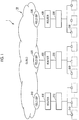
- a remote monitoring system 1 includes a central data collecting device 10 and a field data collecting devices 210, 220, and 230.
- the central data collecting device 10 is located remotely from the field data collecting devices 210, 220, and 230.
- the central data collecting device 10 and the field data collecting device 210 are connected to each other to be able to perform communication via a router 410 and a field Internet service provider 510.
- the central data collecting device 10 and the field data collecting device 220 are connected to each other to be able to perform communication via a router 420 and a field Internet service provider 520.
- the central data collecting device 10 and the field data collecting device 230 are connected to each other to be able to perform communication via a router 430 and a field Internet service provider 530.
- a cloud is used as the central data collecting device 10.
- monitoring data from the field data collecting devices 210, 220, and 230 of respective site areas is collected in the central data collecting device 10.
- the remote monitoring system 1 of the present embodiment includes three field data collecting devices, but the number of field data collecting devices is not limited to three, and may be any number. In other words, the remote monitoring system 1 may include a single field data collecting device, and may include two or four or more field data collecting devices.
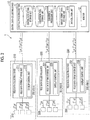
- the central data collecting device 10 includes a central processing section 11 and a monitor 12. As will be described later, the central data collecting device 10 converts each data string into display format data in the central processing section 11, and displays information related to the display format data on the monitor 12.
- the field data collecting device 210 is disposed in a site area A in which a plurality of monitoring target apparatuses 310 are provided, and is connected to each of the monitoring target apparatuses 310 so as to be able to perform communication in a wireless or wired manner.
- the field data collecting device 210 includes a field data string storage unit 211 and an overlap control unit 215.
- the field data collecting device 220 is disposed in a site area B in which a plurality of monitoring target apparatuses 320 are provided, and is connected to each of the monitoring target apparatuses 320 so as to be able to perform communication in a wireless or wired manner.
- the field data collecting device 220 includes a field data string storage unit 221 and an overlap control unit 225.
- the field data collecting device 230 is disposed in a site area C in which a plurality of monitoring target apparatuses 330 are provided, and is connected to each of the monitoring target apparatuses 330 so as to be able to perform communication in a wireless or wired manner.
- the field data collecting device 230 includes a field data string storage unit 231 and an overlap control unit 235.
- a program which will be described later is executed, and thus the program causes a computer of the field data collecting device 210 to function as the field data string storage unit 211 and the overlap control unit 215.
- the program causes a computer of the field data collecting device 220 to function as the field data string storage unit 221 and the overlap control unit 225.
- the program causes a computer of the field data collecting device 230 to function as the field data string storage unit 231 and the overlap control unit 235.
- the plurality of monitoring target apparatuses 310, 320, and 330 are apparatuses monitored by the remote monitoring system 1, and transmit operation data thereof to the remote monitoring system 1.
- the plurality of monitoring target apparatuses 310, 320, and 330 are a combination of an air conditioner, a chiller, a water heater, a boiler, and the like.
- each model of the plurality of monitoring target apparatuses 310 is any one of four types of models such as k1, k2, k3, and k4.
- each model of the plurality of monitoring target apparatuses 320 is any one of four types of models such as k1, k2, k3, and k4.
- each model of the plurality of monitoring target apparatuses 330 is any one of four types of models such as k1, k2, k3, and k4.
- the plurality of monitoring target apparatuses 310 respectively transmit data strings a1, a2, a3,... to the field data collecting device 210 according to respective operation states thereof.
- the field data collecting device 210 collects the data strings a1, a2, a3,... respectively transmitted according to operation states.
- the field data string storage unit 211 stores the data strings a1, a2, a3,... collected by the field data collecting device 210.
- the transmitted data string are operation data (operation stoppage, an operation mode, a set temperature, the room temperature, a compressor operation frequency, the temperature of each portion, a pressure, or the like) of each monitoring target apparatus, and is, for example, log data output from each monitoring target apparatus.
- the field data collecting device 220 collects the data strings b1, b2, b3,... respectively transmitted from the plurality of monitoring target apparatuses 320 according to operation states.
- the field data string storage unit 221 stores the data strings b1, b2, b3,... collected by the field data collecting device 220.
- the field data collecting device 230 collects the data strings c1, c2, c3,... respectively transmitted from the plurality of monitoring target apparatuses 330 according to operation states.
- the field data string storage unit 231 stores the data strings c1, c2, c3,... collected by the field data collecting device 230.
- the data strings a1, a2, a3,..., the data strings b1, b2, b3,..., and the data strings c1, c2, c3,... are all data strings formed of raw engineering values.
- the data strings a1, a2, a3,..., the data strings b1, b2, b3,..., and the data strings c1, c2, c3,... are data strings having output formats of the respective monitoring target apparatuses.
- Each of the field data string storage units 211, 221, and 231 does not analyze the data strings, stores the data strings in a state in which the output format of each monitoring target apparatus is maintained, and transmits the data strings to the central data collecting device 10 in a state in which the output format of each monitoring target apparatus is maintained.
- the central processing section 11 functionally includes a central data string storage unit 111, a conversion tool storage unit 112, a conversion processing unit 113, a display format data storage unit 114, and a data deletion unit 115.
- a program which will be described later is executed, and thus the program causes a computer to function as the central data string storage unit 111, the conversion tool storage unit 112, the conversion processing unit 113, the display format data storage unit 114, and the data deletion unit 115.
- the central data string storage unit 111 stores the data strings a1, a2, a3,..., the data strings b1, b2, b3,..., and the data strings c1, c2, c3,... respectively transmitted from the field data collecting devices 210, 220, and 230 transmitted to the central data collecting device 10 as accumulated data groups which will be described later in a state in which the output format of each monitoring target apparatus is maintained.
- the conversion tool storage unit 112 stores in advance respective conversion tools related to the models k1, k2, k3, and k4 of the plurality of monitoring target apparatuses 310.
- the conversion tools for example, a data conversion table and a calculation formula are used.
- the conversion processing unit 113 converts the data strings a1, a2, a3,..., the data strings b1, b2, b3,..., and the data strings c1, c2, c3,... into display format data by using conversion tools related to the data strings stored in the central data string storage unit 111.
- the display format data as a result of the conversion is, for example, numerical value data or a graph.
- the display format data storage unit 114 stores each display format data obtained through conversion in the conversion processing unit 113.
- the display format data storage unit 114 transmits the stored display format data to the monitor 12 in response to a request from the central processing section 11.
- the data deletion unit 115 deletes an overlap portion which will be described later and is transmitted to the central data collecting device 10 so as to overlap data strings, from the data strings.
- the monitor 12 receives the display format data transmitted from the display format data storage unit 114, and displays information regarding related to the display format data.
- the information displayed on the monitor 12 is, for example, numerical value data or a graph.
- the displayed numerical value data or graph may be information indicating data regarding a specific operation state of a specific monitoring target apparatus of a specific site area, and may be information indicating comparison between pieces of data regarding a plurality of site areas, a plurality of monitoring target apparatuses, or a plurality of operation states.
- a data string collected from each monitoring target apparatus 310 by the field data collecting device 210 is a data string having 1 byte (8 bits) as a basic length, and is pieces of data which are arranged without interval on the basis of data regarding an operation state.
- a data string of 512 bytes is a data which is collected once, and the data string of 512 bytes is collected once 10 seconds.
- Each data string of 512 bytes includes a single piece of a plurality of pieces of operation data of each monitoring target apparatus 310.
- the field data string storage unit 211 of the field data collecting device 210 accumulates and stores the data strings a1, a2, a3,... collected by the field data collecting device 210 for the respective monitoring target apparatuses 310 (for the respective data strings a1, a2, a3,).
- the field data string storage unit 211 stores the data strings a1, a2, a3,... in a time series in which the field data collecting device 210 collects the data strings a1, a2, a3,....
- the field data string storage unit 211 stores an initial data string of 512 bytes collected by the field data collecting device 210 from the time point of 00 minutes 00 seconds (00:00) to the time point of 00 minutes 10 seconds (00:10).
- the field data string storage unit 211 stores a second data string of 512 bytes collected by the field data collecting device 210 from the time point of 00 minutes 10 seconds (00:10) to the time point of 00 minutes 20 seconds (00:20).
- the field data string storage unit 211 sequentially stores a third data string of 512 bytes collected by the field data collecting device 210 from the time point of 00 minutes 20 seconds (00:20) to the time point of 00 minutes 30 seconds (00:30).
- the field data string storage unit 211 stores a fourth data string of 512 bytes collected by the field data collecting device 210 from the time point of 00 minutes 30 seconds (00:30) to the time point of 00 minutes 40 seconds (00:40).
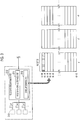
- the field data string storage unit 211 stores the data strings a1, a2, a3,... in a storage structure as illustrated on a lower right part in Fig. 3 , for example.
- numbers illustrated on the left of each data string of 512 bytes indicate a time period in which the field data collecting device 210 collects each data string of 512 bytes.
- the field data string storage unit 211 stores the respective data strings a1, a2, a3,... corresponding to one hour from the time point of 00 minutes 00 seconds (00:00) to the time point of 60 minutes 00 seconds (60:00).
- the overlap control unit 215 sequentially reads, as an accumulated data group with a predetermined record length, the data strings a1, a2, a3,... corresponding to a predetermined time among the accumulated data strings a1, a2, a3,..., from the field data string storage unit 211.
- the predetermined record length of each accumulated data group may be set from the field data collecting device 210 or the central data collecting device 10.
- the predetermined record length is set to, for example, 1 minute to 15 minutes, and, in the present embodiment, the predetermined record length is set to 15 minutes.
- the overlap control unit 215 sequentially transmits the respective accumulated data groups which are sequentially read, to the central data collecting device 10 at a predetermined time interval.
- the time interval at which the respective accumulated data groups are sequentially transmitted may be set from the field data collecting device 210 or the central data collecting device 10.
- the overlap control unit 215 sequentially reads the respective accumulated data groups such that each read accumulated data group overlaps the previously read accumulated data group in the data strings a1, a2, a3,... corresponding to a predetermined time. In other words, the overlap control unit 215 sequentially reads the respective accumulated data groups such that the respective accumulated data groups which are sequentially read overlap the read anteroposterior accumulated data groups in data strings.
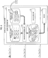
- FIG. 4 illustrates accumulated data groups obtained by sequentially reading data strings with a record length of 15 minutes as accumulated data groups a1-1, a1-2, a1-3, and a1-4 among the data strings a1 which are accumulated and stored in a time series in the storage structure illustrated in Fig. 3 .
- numbers illustrated on the left of each data string of 512 bytes indicate a time period in which the field data collecting device 210 collects each data string of 512 bytes.
- the overlap control unit 215 reads the accumulated data group a1-1 with a record length of 15 minutes from the time point of 00 minutes 00 seconds to the time point of 15 minutes 00 seconds from the field data string storage unit 211.
- the overlap control unit 215 reads the accumulated data group a1-2 to overlap the previously read accumulated data group a1-1 in the data strings a1.
- the overlap control unit 215 reads the accumulated data group a1-2 with a record length of 15 minutes from the time point of 05 minutes 00 seconds to the time point of 20 minutes 00 seconds from the field data string storage unit 211 such that the data strings a1 corresponding to 10 minutes overlap the accumulated data group a1-1 in an overlap portion OL.
- the overlap control unit 215 reads the accumulated data group a1-3 to overlap the previously read accumulated data group a1-2 in the data strings a1.
- the overlap control unit 215 reads the accumulated data group a1-3 with a record length of 15 minutes from the time point of 10 minutes 00 seconds to the time point of 25 minutes 00 seconds from the field data string storage unit 211 such that the data strings a1 corresponding to 10 minutes overlap the accumulated data group a1-2 in an overlap portion OL.
- the overlap control unit 215 reads the accumulated data group a1-4 to overlap the previously read accumulated data group al-3 in the data strings a1.
- the overlap control unit 215 reads the accumulated data group a1-4 with a record length of 15 minutes from the time point of 15 minutes 00 seconds to the time point of 30 minutes 00 seconds from the field data string storage unit 211 such that the data strings a1 corresponding to 10 minutes overlap the accumulated data group a1-3 in an overlap portion OL.
- the overlap control unit 215 transmits the respective read data groups to the central data collecting device 10 at a predetermined time interval.
- a time for which the respective accumulated data groups overlap each other in the overlap portion OL is determined on the basis of a record length of each accumulated data group read from the field data string storage unit 211 by the overlap control unit 215 and a time interval at which the overlap control unit 215 transmits each accumulated data group to the central data collecting device 10.
- the overlap control unit 215 may read an accumulated data group with a record length of 15 minutes once 5 minutes from the field data string storage unit 211. Therefore, the overlap control unit 215 may read each data group at a record length of 15 minutes, and may transmit each data group to the central data collecting device 10 at the interval of 5 minutes.
- the overlap control unit 215 transmits the data strings a1, a2, a3,... to the central data collecting device 10 in a state in which an output format of each monitoring target apparatus 310 is maintained.
- the overlap control unit 215 may summarize each read data group into a single piece of file data, and may transmit the summarized file data to the central data collecting device 10 in a state in which an output format of each monitoring target apparatus 310 is maintained.
- the overlap control unit 215 may summarize each read data group into a single file folder, and may transmit the summarized file folder to the central data collecting device 10 in a state in which an output format of each monitoring target apparatus 310 is maintained.
- the overlap control unit 215 transmits each data group to the central data collecting device 10 in a state in which an output format of each monitoring target apparatus 310 is maintained, a correspondence relationship between a data string and the time at which the data string is collected and a correspondence relationship between a data string and a monitoring target apparatus from which the data string is collected may be unclear.
- leading data for example, hatched data in Fig. 3
- each monitoring target apparatus may be used among respective data strings of 512 bytes.
- leading data for example, hatched data in Fig. 3
- the central data collecting device 10 can identify a collecting time of each data string in the field data collecting device 210 or a monitoring target apparatus which outputs each data string.
- the overlap control unit 215 may write identification data of each monitoring target apparatus into each file or each folder.
- the function of the field data collecting device 210 has been described in detail, but the field data collecting devices 220 and 230 also have the same function as that of the field data collecting device 210.
- the field data collecting device can accumulate data strings to the maximum amount thereof.
- the field data collecting device accumulates the data strings a1, a2, a3,... corresponding to one hour, and thus the field data collecting device can accumulate data strings corresponding to up to one hour even if there is a failure in the central data collecting device 10 or a failure in a communication line.
- the maximum amount is determined on the basis of a memory capacity of the field data collecting device.
- the data deletion unit 115 deletes a data string in which data is not omitted as an overlap portion among the data strings stored in the central data string storage unit 111.
- the central data collecting device 10 deletes overlapping data from the accumulated data groups which are sequentially transmitted from each field data collecting device. Therefore, the field data string storage unit 211 combines and stores the accumulated data groups to be stored in order to obtain a series of data strings (recorded data every 10 seconds) without data strings of 512 bytes of which collecting times (times at which the field data collecting device collects the data strings) overlap each other.
- Overlapping data is determined by using an added serial number which is added to each data string of 512 bytes.
- the above-described identification data of a collecting time of each data string of 512 bytes may be used.
- a data complementation function of the central data collecting device 10 will be described.
- the central data collecting device 10 can complement data strings with another accumulated data group.
- the field data collecting device 210 transmits each data group with a record length of 15 minutes to the central data collecting device 10 at the interval of 5 minutes.
- data strings from the time point of 15 minutes 00 seconds to the time point of 20 minutes 00 seconds to be added to the accumulated data group a1-2 or data strings from the time point of 20 minutes 00 seconds to the time point of 25 minutes 00 seconds to be added to the accumulated data group a1-3 are an omission portion DF.
- the central data collecting device 10 complements the data strings of the omission portion DF with data strings of the accumulated data group a1-4 from the time point of 15 minutes 00 seconds to the time point of 25 minutes 00 seconds.
- the data strings of the accumulated data group a1-1 from the time point of 00 minutes to 00 seconds to the time point of 15 minutes 00 seconds are combined with the data strings of the accumulated data group a1-4 from the time point of 15 minutes to 00 seconds to the time point of 30 minutes 00 seconds, so as to be stored in the central data string storage unit 111 as a series of data strings.
- data to be included in a single data string (data string of 512 bytes), data to be included, the capacity occupied by predetermined data, and an order of pieces of data being arranged differ depending on a model of a monitoring target apparatus.
- a multiplier of each piece of numerical value data also differs depending on a model of a monitoring target apparatus.
- the conversion processing unit 113 is required to specify a model of a monitoring target apparatus having transmitted each data string, and to convert the data string into display format data by using a conversion tool related to the model. Therefore, the central data collecting device functions as follows.
- the central data string storage unit 111 transmits stored data strings to the conversion processing unit 113.
- a series of data strings obtained by deleting an overlap portion in the data deletion unit 115 is transmitted to the conversion processing unit 113.
- the conversion processing unit 113 specifies a monitoring target apparatus on the basis of an order of receiving the received data strings, a timing of receiving the received data strings, identification information attached to the received data strings, and the like.
- the conversion processing unit 113 stores in advance a correspondence relationship between each monitoring target apparatus and a model of the monitoring target apparatus. Consequently, on the basis of the specified monitoring target apparatus, a model of the monitoring target apparatus having transmitted the received data strings is specified.
- the conversion processing unit 113 reads a conversion tool related to the specified model from the conversion tool storage unit 112.
- the conversion processing unit 113 converts each data string having an output format of each monitoring target apparatus into display format data by using the read conversion tool.
- the conversion processing unit 113 specifies the model k1.
- the conversion processing unit 113 reads a conversion tool related to the model k1 from the conversion tool storage unit 112.
- the conversion processing unit 113 converts the data strings a1 having the output format of the monitoring target apparatus 310 of the model k1 into display format data A1 by using the read conversion tool.
- the conversion processing unit 113 specifies the model k4.
- the conversion processing unit 113 reads a conversion tool related to the model k4 from the conversion tool storage unit 112.
- the conversion processing unit 113 converts the data strings a2 having the output format of the monitoring target apparatus 310 of the model k4 into display format data A2 by using the read conversion tool.
- the conversion processing unit 113 converts the respective data strings a1, a2, a3,... into the pieces of display format data A1, A2, A3,... by using the conversion tools related to the data strings. Similarly, the conversion processing unit 113 converts the respective data strings b1, b2, b3,... into the pieces of display format data B1, B2, B3,... by using conversion tools related to the data strings. Similarly, the conversion processing unit 113 converts the respective data strings c1, c2, c3,... into the pieces of display format data C1, C2, C3,... by using conversion tools related to the data strings.
- the conversion processing unit 113 converts a data string having an output format of a monitoring target apparatus into display format data as follows.
- the data conversion table replaces a data string having an output format of a monitoring target apparatus with numerical value data having a corresponding predetermined data length (1 bit, 1 byte, 2 bytes, 4 bytes, or the like), the unit (°C, Pa, Hz, a pulse, A, deg, Hr, or the like) data, and data indicating the presence or absence of a sign ( ⁇ ).
- the calculation formula defines a multiplier of each piece of numerical value data.
- the conversion processing unit 113 reads a data conversion table related to the model k2, and reads a calculation formula related to the model k2.
- the read calculation formula is " ⁇ 0.1".
- the data conversion table outputs numerical value data, unit data, and data indicating the presence or absence of a sign ( ⁇ ) of each piece of operation data from a single data string.
- the calculation formula defines a multiplier of each piece of numerical value data.
- the display format data A1, A2, A3,..., the display format data B1, B2, B3,..., and the display format data C1, C2, C3,... obtained through conversion in the conversion processing unit 113 are stored in the display format data storage unit 114 and are also or then transmitted to the monitor 12.
- This case may be coped with by modifying the central data collecting device 10 without modifying the field data collecting device 210.
- conversion tools related to the new model k5 are added to the conversion tool storage unit 112, and the conversion processing unit 113 is modified to be able to specify the new model k5.
- a program is executed, and thus the program causes the computer of the central data collecting device 10 to function as the conversion tool storage unit 112, the conversion processing unit 113, and the data deletion unit 115. Therefore, the program for the computer of the central data collecting device 10 is rewritten, and thus the conversion tool storage unit 112 and the conversion processing unit 113 may be modified to cope with the new model k5.
- the conversion processing unit 113 Since the modification corresponding to the new model k5 is performed, in a case where the data strings a1' is received after the modification, the conversion processing unit 113 specifies the new model k5, and reads the conversion tools related to the new model k5 from the conversion tool storage unit 112. The conversion processing unit 113 converts the data strings a1' having an output format of the new model k5 into display format data A1'.
- the work of adding a new model may be performed such that a monitoring target apparatuses of a new model is introduced in each site area instead of some of a plurality of monitoring target apparatuses as described above, and may be performed such that a monitoring target apparatuses of a new model is introduced in addition to a plurality of monitoring target apparatuses.
- conversion tools related to increased models may be added to the conversion tool storage unit, and the conversion processing unit may be modified such that the increased models can be specified, without modifying the field data collecting device.
- the field data collecting devices 210, 220, and 230 accumulate data strings which are output from the monitoring target apparatuses 310, 320, and 330 according to operation states thereof, and transmits the data strings to the central data collecting device 10 as accumulated data groups.
- the data strings are accumulated, and are transmitted to the central data collecting device 10 as the accumulated data groups, a load on a CPU of the central data collecting device 10 can be reduced, and a communication frequency with the field data collecting devices 210, 220, and 230 can be reduced.
- the thickness of a communication line (a line speed or a line capacity) on the central data collecting device 10 side may not be increased even if the number of monitoring target apparatuses 310, 320, and 330 in the field is increased.
- the remote monitoring system 1 can complement a data omission portion with another accumulated data group. Therefore, it is possible to minimize data omission caused by a failure in the central data collecting device or a failure in a communication line.
- the remote monitoring system 1 may set a record length and a transmission time interval of an accumulated data group. Therefore, since an overlap amount can be adjusted according to a communication state, the remote monitoring system 1 can increase communication efficiency within a range of reduce or even eliminate data omission.
- the central data collecting device 10 can delete an overlap portion without data omission, and thus the remote monitoring system 1 can reduce a total amount of data stored in the central data collecting device 10.
- the remote monitoring system 1 converts the respective data strings output from the monitoring target apparatuses 310, 320, and 330 into display format data not in the field data collecting devices 210, 220, and 230 but in the central data collecting device 10. In other words, the remote monitoring system 1 performs analysis of information regarding the monitoring target apparatuses 310, 320, and 330 in the central data collecting device 10.
- the remote monitoring system 1 can alleviate work of modifying the field data collecting devices 210, 220, and 230.
- the remote monitoring system 1 can alleviate work of updating a program of the collecting device due to function enhancement of the field data collecting devices 210, 220, and 230, and can thus alleviate hardware remodeling work such as a memory increase due to the function enhancement.
- the remote monitoring system 1 can unify management of conversion tools for converting each data string into display format data in the central data collecting device 10, and can thus cope with addition of a new model and an increase of the number of models of monitoring target apparatuses with high efficiency in a short period of time.
- Communication data between the field data collecting devices 210, 220, and 230 and the central data collecting device 10 is a raw engineering value before being analyzed, and is thus hard to analyze even if the data is intercepted. Therefore, the remote monitoring system 1 can reduce the risk of information leakage.
- a data format of each data string collected by the central data collecting device 10 is an output format of each of the monitoring target apparatuses 310, 320, and 330.
- the central data collecting device 10 collects respective data strings output from the monitoring target apparatuses 310, 320, and 330 in a state in which output formats of the monitoring target apparatuses 310, 320, and 330 are maintained, the remote monitoring system 1 is not required to convert a data format of each data string in the field data collecting devices 210, 220, and 230.
- the field data collecting devices 210, 220, and 230 do not convert data formats, and thus the remote monitoring system 1 can alleviate work of modifying the field data collecting devices 210, 220, and 230.
- the remote monitoring system 1 Since display format data is converted into a character or a graph in the conversion processing unit 113, the remote monitoring system 1 converts the data strings into format data suitable to display the character or the graph. Therefore, the remote monitoring system 1 is suitable for displaying a character or a graph.
- a data conversion table and a calculation formula are used to convert each data string into display format data, and thus the central data collecting device 10 can acquire display format data having a large amount of information from a data string having a small amount of data. Therefore, the remote monitoring system 1 can transmit a large amount of information from the field data collecting devices 210, 220, and 230 to the central data collecting device 10 for a short communication time.
- the field data string storage units 211, 221, and 231 accumulate respective data strings, and transmit the data strings to the central data collecting device 10 at predetermined time intervals, and thus the accumulated data strings can be transmitted from the field data collecting devices 210, 220, and 230 to the central data collecting device 10 at the predetermined time intervals.
- there is communication interruption or communication abnormality a communication failure or communication noise
- the field data string storage units 211, 221, and 231 accumulate respective data strings, and transmit the data strings to the central data collecting device 10 at predetermined time intervals. Consequently, the remote monitoring system 1 can transmit the accumulated data strings from the field data collecting devices 210, 220, and 230 to the central data collecting device 10 at the predetermined time intervals by avoiding a time period in which communication cannot be performed.
- the remote monitoring system 1 can accumulate data strings in the field data collecting devices 210, 220, and 230 in the time period in which the data strings cannot be transmitted.
- the remote monitoring system 1 can transmit the data strings from the field data collecting devices 210, 220, and 230 to the central data collecting device 10 after the time period in which the data strings cannot be transmitted.
- a remote monitoring system according to a second embodiment of the present invention will be described with reference to Fig. 7 .
- a remote monitoring system of the present embodiment is fundamentally the same as the remote monitoring system of the first embodiment, but is different in that the field data collecting device further includes a display format data reception unit.
- a remote monitoring system 1' includes a central data collecting device 10' and a field data collecting devices 210', 220', and 230'.
- the field data collecting device 210' includes a field data string storage unit 211, an overlap control unit 215, and a display format data reception unit 212.
- the overlap control unit 215 transmits the data strings a1, a2, a3,... to the central data collecting device 10' as accumulated data groups in a state in which an output format of each monitoring target apparatus is maintained.
- the field data collecting device 220' includes a field data string storage unit 221, an overlap control unit 225, and a display format data reception unit 222.
- the overlap control unit 225 transmits the data strings b1, b2, b3,... to the central data collecting device 10' as accumulated data groups in a state in which an output format of each monitoring target apparatus is maintained.
- the field data collecting device 230' includes a field data string storage unit 231, an overlap control unit 235, and a display format data reception unit 232.
- the overlap control unit 235 transmits the data strings c1, c2, c3,... to the central data collecting device 10' as accumulated data groups in a state in which an output format of each monitoring target apparatus is maintained.
- a program which will be described later is executed, and thus the program causes a computer of the field data collecting device 210' to function as the field data string storage unit 211, the overlap control unit 215, and the display format data reception unit 212.
- the program causes a computer of the field data collecting device 220' to function as the field data string storage unit 221, the overlap control unit 225, and the display format data reception unit 222.
- the program causes a computer of the field data collecting device 230' to function as the field data string storage unit 231, the overlap control unit 235, and the display format data reception unit 232.
- the remote monitoring system 1' of the present embodiment includes three field data collecting devices, but the number of field data collecting devices is not limited to three, and may be any number. In other words, the remote monitoring system 1' may include a single field data collecting device, and may include two or four or more field data collecting devices.
- the central data collecting device 10' includes a central processing section 11' and a monitor 12.
- the central processing section 11' functionally includes a central data string storage unit 111, a conversion tool storage unit 112, a conversion processing unit 113, a display format data storage unit 114', and a data deletion unit 115.
- a program which will be described later is executed, and thus the program causes a computer to function as the central data string storage unit 111, the conversion tool storage unit 112, the conversion processing unit 113, the display format data storage unit 114', and the data deletion unit 115.
- the display format data storage unit 114' stores each display format data obtained through conversion in the conversion processing unit 113.
- the display format data storage unit 114' transmits the stored display format data to the monitor 12 in response to a request from the central processing section 11'.
- the display format data storage unit 114' transmits each piece of stored display format data to a field data collecting device having transmitted a data string which is a basis of the display format data.
- the display format data storage unit 114' transmits the display format data A1, A2, A3,... to the field data collecting device 210', transmits the display format data B1, B2, B3,... to the field data collecting device 220', and transmits the display format data C1, C2, C3,... to the field data collecting device 230'.
- the display format data reception unit 212 of the field data collecting device 210' receives the display format data A1, A2, A3,... transmitted from the display format data reception unit 212.
- the display format data storage unit 114' of the field data collecting device 220' receives the display format data B1, B2, B3,...
- the display format data reception unit 232 of the field data collecting device 230' receives the display format data C1, C2, C3,....
- display format data obtained through conversion in the central data collecting device 10' can be received by each field data collecting device. Therefore, a user can analyze information regarding a monitoring target apparatus in each site area.
- the field data collecting device disposed in a site area in which respective monitoring target apparatuses are provided collects data strings which are output from the monitoring target apparatuses according to operation states thereof (S1: field data collecting step).
- the field data collecting device transmits the data strings to the central data collecting device (S2: field data transmission step).
- the overlap control unit of the field data collecting device sequentially reads data strings with a predetermined record length to overlap each other among data strings accumulated and stored as accumulated data groups in the field data string storage unit, and sequentially transmits the data strings to the central data collecting device.
- the central data collecting device collects the data strings from the field data collecting device as accumulated data groups (S3: central data collecting step).
- the central data collecting device converts the data strings into display format data by using conversion tools related to the data strings among conversion tools based on models of the monitoring target apparatuses (S4: data conversion step). After the data conversion step S4 is performed, the display format data obtained through the conversion is displayed on the monitor (S5: data display step).
- the program for realizing various functions of the central processing section or the field data collecting device is recorded on a computer readable recording medium, and the program recorded on the recording medium is read to a computer system and is executed such that various processes are performed.
- procedures of various processes in each CPU described above are stored in a computer readable recording medium in a format of the program, and the program is read and executed by the computer such that the various processes are performed.
- the computer readable recording medium is, for example, a magnetic disk, a magnetooptical disk, a CD-ROM, a DVD-ROM, and a semiconductor memory.
- the computer program may be delivered to a computer via communication line, and the computer having received the delivery may execute the program.
- the remote monitoring system may receive a notification of abnormality in each monitoring target apparatus.
- a remote monitoring system 1 receives the abnormality signal error1 of the monitoring target apparatus 310.
- the remote monitoring system 1" having received the abnormality signal error1 immediately reports the abnormality signal error1 to the central data collecting device 10 without analyzing or accumulating the abnormality signal error 1 in the field data collecting device 210. As illustrated in Fig. 9 , as the report to the central data collecting device 10, the remote monitoring system 1" transmits the received abnormality signal error1 to the monitor 12. In a case where the abnormality signal error1 is received, the monitor 12 immediately displays the abnormality in the monitoring target apparatus 310. According to the present modification example, the remote monitoring system 1" immediately displays abnormality in a monitoring target apparatus without analyzing or accumulating an abnormality report for the monitoring target apparatus, and thus a user can check the abnormality in the monitoring target apparatus in real time without delay.
- the central data collecting device may detect abnormality in each piece of operation data of each monitoring target apparatus.
- the central data collecting device collects respective pieces of operation data of the monitoring target apparatuses collected in each field data collecting device.
- an abnormality determination criterion for each model for example, a threshold value for each model
- abnormality in each piece of operation data of each monitoring target apparatus can be determined according to a determination criterion specific to a model.
- the abnormality determination criterion for each model can be learned by using the collected operation data.
- the remote monitoring system transmits an accumulated data group from the field data collecting device to the central data collecting device in an output format of a monitoring target apparatus, but may transmit an accumulated data group from the field data collecting device to the central data collecting device in any data format.
- display format data may be transmitted from the field data collecting device to the central data collecting device.
- each data string which can be collected once from each monitoring target apparatus by the field data collecting device is a data string of 512 bytes, but a size of a data string is not limited to 512 bytes, and may be a larger size or a smaller size.
- the field data collecting device is connected to a plurality of monitoring target apparatuses, but, as a modification example, the field data collecting device may be communicably connected to only a single monitoring target apparatus.
- each field data collecting device of the remote monitoring system is remote from the central data collecting device.
- the remote monitoring system may include a field data collecting device located close by as a modification example.
- a plurality of monitoring target apparatuses are a combination of an air conditioner, a chiller, a water heater, a boiler, and the like, but monitoring target apparatuses are not limited to the combination.
- a plurality of monitoring target apparatuses may be a combination of air conditioners of a plurality of models.
- a communication process between collecting devices remote from each other is hardly a burden even if the number of monitoring target apparatuses in the field is increased.
Landscapes
- Engineering & Computer Science (AREA)
- Computer Networks & Wireless Communication (AREA)
- General Engineering & Computer Science (AREA)
- Physics & Mathematics (AREA)
- General Physics & Mathematics (AREA)
- Automation & Control Theory (AREA)
- Selective Calling Equipment (AREA)
- Air Conditioning Control Device (AREA)
- Telephonic Communication Services (AREA)
Applications Claiming Priority (2)
| Application Number | Priority Date | Filing Date | Title |
|---|---|---|---|
| JP2016215315A JP2018074508A (ja) | 2016-11-02 | 2016-11-02 | 遠隔監視システム、中央データ収集装置、現地データ収集装置、遠隔監視方法及びプログラム |
| PCT/JP2017/038638 WO2018084059A1 (ja) | 2016-11-02 | 2017-10-26 | 遠隔監視システム、中央データ収集装置、現地データ収集装置、遠隔監視方法及びプログラム |
Publications (2)
| Publication Number | Publication Date |
|---|---|
| EP3451685A1 true EP3451685A1 (de) | 2019-03-06 |
| EP3451685A4 EP3451685A4 (de) | 2019-07-24 |
Family
ID=62076028
Family Applications (1)
| Application Number | Title | Priority Date | Filing Date |
|---|---|---|---|
| EP17867041.0A Withdrawn EP3451685A4 (de) | 2016-11-02 | 2017-10-26 | Fernüberwachungssystem, zentrale datenerfassungsvorrichtung, felddatenerfassungsvorrichtung, fernüberwachungsverfahren und programm |
Country Status (3)
| Country | Link |
|---|---|
| EP (1) | EP3451685A4 (de) |
| JP (1) | JP2018074508A (de) |
| WO (1) | WO2018084059A1 (de) |
Cited By (1)
| Publication number | Priority date | Publication date | Assignee | Title |
|---|---|---|---|---|
| CN115104320A (zh) * | 2020-02-12 | 2022-09-23 | 大金工业株式会社 | 数据收集系统、接收侧装置以及数据收集方法 |
Family Cites Families (8)
| Publication number | Priority date | Publication date | Assignee | Title |
|---|---|---|---|---|
| US6195018B1 (en) * | 1996-02-07 | 2001-02-27 | Cellnet Data Systems, Inc. | Metering system |
| JP2002315082A (ja) * | 2001-04-13 | 2002-10-25 | Toshiba Corp | 監視制御システム |
| JP2005018152A (ja) * | 2003-06-23 | 2005-01-20 | Shimadzu System Solutions Co Ltd | 制御/監視システム |
| JP2011188338A (ja) * | 2010-03-10 | 2011-09-22 | Seiko Epson Corp | 無線送信機、データ収集システム及びデータ通信方法 |
| JP5715585B2 (ja) * | 2012-02-20 | 2015-05-07 | 株式会社日立製作所 | 信号伝送装置及び方法並びに変電所監視制御システム |
| CN104737551B (zh) * | 2012-10-23 | 2018-05-25 | 三菱电机株式会社 | 通信装置、监视系统以及通信方法 |
| JP6112552B2 (ja) * | 2013-03-29 | 2017-04-12 | 四国電力株式会社 | 情報収集システム |
| JP2015095792A (ja) * | 2013-11-13 | 2015-05-18 | 富士通テレコムネットワークス株式会社 | 通信システム、通信装置および通信方法 |
-
2016
- 2016-11-02 JP JP2016215315A patent/JP2018074508A/ja active Pending
-
2017
- 2017-10-26 WO PCT/JP2017/038638 patent/WO2018084059A1/ja not_active Ceased
- 2017-10-26 EP EP17867041.0A patent/EP3451685A4/de not_active Withdrawn
Cited By (1)
| Publication number | Priority date | Publication date | Assignee | Title |
|---|---|---|---|---|
| CN115104320A (zh) * | 2020-02-12 | 2022-09-23 | 大金工业株式会社 | 数据收集系统、接收侧装置以及数据收集方法 |
Also Published As
| Publication number | Publication date |
|---|---|
| WO2018084059A1 (ja) | 2018-05-11 |
| JP2018074508A (ja) | 2018-05-10 |
| EP3451685A4 (de) | 2019-07-24 |
Similar Documents
| Publication | Publication Date | Title |
|---|---|---|
| CN111726358A (zh) | 攻击路径分析方法、装置、计算机设备及存储介质 | |
| CN110647447B (zh) | 用于分布式系统的异常实例检测方法、装置、设备和介质 | |
| CA2685901A1 (en) | Diagnostic and trouble-shooting methods in a wireless control and sensor network | |
| EP3220271B1 (de) | Datenerfassungsvorrichtung, datenerfassungssystem, steuerungsverfahren und programm | |
| CN108153654A (zh) | 一种日志收集方法及装置 | |
| CN112800061A (zh) | 一种数据存储方法、装置、服务器及存储介质 | |
| CN102769533A (zh) | 数据处理方法和数据处理装置 | |
| CN113064890A (zh) | 一种运营商数据的质量评估方法、装置、服务器及介质 | |
| CN112817814A (zh) | 异常监控方法、系统、存储介质及电子装置 | |
| CN102395834B (zh) | 空气调节系统诊断装置 | |
| KR20190020491A (ko) | 지상국 시스템의 통합 상태 모니터링 방법 | |
| CN110971488A (zh) | 一种数据处理方法、装置、服务器和存储介质 | |
| EP3451685A1 (de) | Fernüberwachungssystem, zentrale datenerfassungsvorrichtung, felddatenerfassungsvorrichtung, fernüberwachungsverfahren und programm | |
| EP3448054A1 (de) | Fernüberwachungssystem, zentrale datenerfassungsvorrichtung, felddatenerfassungsvorrichtung, fernüberwachungsverfahren und programm | |
| CN106656558B (zh) | 一种延长数据采集服务器存储单元使用寿命的方法 | |
| CN112639844A (zh) | 控制系统以及控制方法 | |
| CN115622830A (zh) | 信息采集方法、装置、电子设备、存储介质及系统 | |
| JP5089716B2 (ja) | データ収集装置、空気調和装置、データ収集システム、データ収集方法及びプログラム | |
| US9686095B2 (en) | Network analysis device, management system, network analysis method and program | |
| CN109933476A (zh) | 一种OpenPOWER服务器性能的显示方法和装置 | |
| CN114443420A (zh) | 一种数据采样方法及相关装置 | |
| CN115484144A (zh) | 一种告警方法、关联关系确定方法、装置及系统 | |
| JP2010124430A (ja) | コンピュータプログラム、データ捕捉装置、データ捕捉方法及びデータ管理システム | |
| CN117978616A (zh) | 一种数据上报方法、数据传输设备、电子设备及存储介质 | |
| CN120711398A (zh) | 工业设备在无线传输控制命令时的抓包方法 |
Legal Events
| Date | Code | Title | Description |
|---|---|---|---|
| STAA | Information on the status of an ep patent application or granted ep patent |
Free format text: STATUS: THE INTERNATIONAL PUBLICATION HAS BEEN MADE |
|
| PUAI | Public reference made under article 153(3) epc to a published international application that has entered the european phase |
Free format text: ORIGINAL CODE: 0009012 |
|
| STAA | Information on the status of an ep patent application or granted ep patent |
Free format text: STATUS: REQUEST FOR EXAMINATION WAS MADE |
|
| 17P | Request for examination filed |
Effective date: 20181126 |
|
| AK | Designated contracting states |
Kind code of ref document: A1 Designated state(s): AL AT BE BG CH CY CZ DE DK EE ES FI FR GB GR HR HU IE IS IT LI LT LU LV MC MK MT NL NO PL PT RO RS SE SI SK SM TR |
|
| AX | Request for extension of the european patent |
Extension state: BA ME |
|
| A4 | Supplementary search report drawn up and despatched |
Effective date: 20190621 |
|
| RIC1 | Information provided on ipc code assigned before grant |
Ipc: H04Q 9/00 20060101AFI20190614BHEP Ipc: H04M 11/00 20060101ALI20190614BHEP |
|
| STAA | Information on the status of an ep patent application or granted ep patent |
Free format text: STATUS: THE APPLICATION HAS BEEN WITHDRAWN |
|
| 18W | Application withdrawn |
Effective date: 20190905 |