EP3451904B1 - Détection de synchronisation de conduction - Google Patents
Détection de synchronisation de conduction Download PDFInfo
- Publication number
- EP3451904B1 EP3451904B1 EP17721304.8A EP17721304A EP3451904B1 EP 3451904 B1 EP3451904 B1 EP 3451904B1 EP 17721304 A EP17721304 A EP 17721304A EP 3451904 B1 EP3451904 B1 EP 3451904B1
- Authority
- EP
- European Patent Office
- Prior art keywords
- segments
- electrophysiological
- candidate
- data
- patient
- Prior art date
- Legal status (The legal status is an assumption and is not a legal conclusion. Google has not performed a legal analysis and makes no representation as to the accuracy of the status listed.)
- Active
Links
Images





Classifications
-
- A—HUMAN NECESSITIES
- A61—MEDICAL OR VETERINARY SCIENCE; HYGIENE
- A61B—DIAGNOSIS; SURGERY; IDENTIFICATION
- A61B5/00—Measuring for diagnostic purposes; Identification of persons
- A61B5/74—Details of notification to user or communication with user or patient; User input means
- A61B5/742—Details of notification to user or communication with user or patient; User input means using visual displays
- A61B5/743—Displaying an image simultaneously with additional graphical information, e.g. symbols, charts, function plots
-
- A—HUMAN NECESSITIES
- A61—MEDICAL OR VETERINARY SCIENCE; HYGIENE
- A61B—DIAGNOSIS; SURGERY; IDENTIFICATION
- A61B5/00—Measuring for diagnostic purposes; Identification of persons
- A61B5/24—Detecting, measuring or recording bioelectric or biomagnetic signals of the body or parts thereof
- A61B5/316—Modalities, i.e. specific diagnostic methods
- A61B5/318—Heart-related electrical modalities, e.g. electrocardiography [ECG]
- A61B5/346—Analysis of electrocardiograms
- A61B5/349—Detecting specific parameters of the electrocardiograph cycle
- A61B5/364—Detecting abnormal ECG interval, e.g. extrasystoles, ectopic heartbeats
-
- A—HUMAN NECESSITIES
- A61—MEDICAL OR VETERINARY SCIENCE; HYGIENE
- A61B—DIAGNOSIS; SURGERY; IDENTIFICATION
- A61B5/00—Measuring for diagnostic purposes; Identification of persons
- A61B5/24—Detecting, measuring or recording bioelectric or biomagnetic signals of the body or parts thereof
- A61B5/25—Bioelectric electrodes therefor
- A61B5/279—Bioelectric electrodes therefor specially adapted for particular uses
- A61B5/28—Bioelectric electrodes therefor specially adapted for particular uses for electrocardiography [ECG]
- A61B5/282—Holders for multiple electrodes
-
- A—HUMAN NECESSITIES
- A61—MEDICAL OR VETERINARY SCIENCE; HYGIENE
- A61B—DIAGNOSIS; SURGERY; IDENTIFICATION
- A61B5/00—Measuring for diagnostic purposes; Identification of persons
- A61B5/24—Detecting, measuring or recording bioelectric or biomagnetic signals of the body or parts thereof
- A61B5/316—Modalities, i.e. specific diagnostic methods
- A61B5/318—Heart-related electrical modalities, e.g. electrocardiography [ECG]
- A61B5/346—Analysis of electrocardiograms
- A61B5/349—Detecting specific parameters of the electrocardiograph cycle
- A61B5/366—Detecting abnormal QRS complex, e.g. widening
-
- A—HUMAN NECESSITIES
- A61—MEDICAL OR VETERINARY SCIENCE; HYGIENE
- A61B—DIAGNOSIS; SURGERY; IDENTIFICATION
- A61B5/00—Measuring for diagnostic purposes; Identification of persons
- A61B5/72—Signal processing specially adapted for physiological signals or for diagnostic purposes
- A61B5/7203—Signal processing specially adapted for physiological signals or for diagnostic purposes for noise prevention, reduction or removal
-
- A—HUMAN NECESSITIES
- A61—MEDICAL OR VETERINARY SCIENCE; HYGIENE
- A61B—DIAGNOSIS; SURGERY; IDENTIFICATION
- A61B5/00—Measuring for diagnostic purposes; Identification of persons
- A61B5/72—Signal processing specially adapted for physiological signals or for diagnostic purposes
- A61B5/7271—Specific aspects of physiological measurement analysis
- A61B5/7275—Determining trends in physiological measurement data; Predicting development of a medical condition based on physiological measurements, e.g. determining a risk factor
-
- A—HUMAN NECESSITIES
- A61—MEDICAL OR VETERINARY SCIENCE; HYGIENE
- A61B—DIAGNOSIS; SURGERY; IDENTIFICATION
- A61B5/00—Measuring for diagnostic purposes; Identification of persons
- A61B5/72—Signal processing specially adapted for physiological signals or for diagnostic purposes
- A61B5/7271—Specific aspects of physiological measurement analysis
- A61B5/7278—Artificial waveform generation or derivation, e.g. synthesizing signals from measured signals
-
- A—HUMAN NECESSITIES
- A61—MEDICAL OR VETERINARY SCIENCE; HYGIENE
- A61B—DIAGNOSIS; SURGERY; IDENTIFICATION
- A61B5/00—Measuring for diagnostic purposes; Identification of persons
- A61B5/74—Details of notification to user or communication with user or patient; User input means
- A61B5/742—Details of notification to user or communication with user or patient; User input means using visual displays
- A61B5/7435—Displaying user selection data, e.g. icons in a graphical user interface
-
- A—HUMAN NECESSITIES
- A61—MEDICAL OR VETERINARY SCIENCE; HYGIENE
- A61B—DIAGNOSIS; SURGERY; IDENTIFICATION
- A61B5/00—Measuring for diagnostic purposes; Identification of persons
- A61B5/74—Details of notification to user or communication with user or patient; User input means
- A61B5/7475—User input or interface means, e.g. keyboard, pointing device, joystick
- A61B5/748—Selection of a region of interest, e.g. using a graphics tablet
- A61B5/7485—Automatic selection of region of interest
-
- G—PHYSICS
- G16—INFORMATION AND COMMUNICATION TECHNOLOGY [ICT] SPECIALLY ADAPTED FOR SPECIFIC APPLICATION FIELDS
- G16H—HEALTHCARE INFORMATICS, i.e. INFORMATION AND COMMUNICATION TECHNOLOGY [ICT] SPECIALLY ADAPTED FOR THE HANDLING OR PROCESSING OF MEDICAL OR HEALTHCARE DATA
- G16H40/00—ICT specially adapted for the management or administration of healthcare resources or facilities; ICT specially adapted for the management or operation of medical equipment or devices
- G16H40/60—ICT specially adapted for the management or administration of healthcare resources or facilities; ICT specially adapted for the management or operation of medical equipment or devices for the operation of medical equipment or devices
- G16H40/63—ICT specially adapted for the management or administration of healthcare resources or facilities; ICT specially adapted for the management or operation of medical equipment or devices for the operation of medical equipment or devices for local operation
-
- G—PHYSICS
- G16—INFORMATION AND COMMUNICATION TECHNOLOGY [ICT] SPECIALLY ADAPTED FOR SPECIFIC APPLICATION FIELDS
- G16H—HEALTHCARE INFORMATICS, i.e. INFORMATION AND COMMUNICATION TECHNOLOGY [ICT] SPECIALLY ADAPTED FOR THE HANDLING OR PROCESSING OF MEDICAL OR HEALTHCARE DATA
- G16H50/00—ICT specially adapted for medical diagnosis, medical simulation or medical data mining; ICT specially adapted for detecting, monitoring or modelling epidemics or pandemics
- G16H50/30—ICT specially adapted for medical diagnosis, medical simulation or medical data mining; ICT specially adapted for detecting, monitoring or modelling epidemics or pandemics for calculating health indices; for individual health risk assessment
-
- A—HUMAN NECESSITIES
- A61—MEDICAL OR VETERINARY SCIENCE; HYGIENE
- A61B—DIAGNOSIS; SURGERY; IDENTIFICATION
- A61B2505/00—Evaluating, monitoring or diagnosing in the context of a particular type of medical care
- A61B2505/05—Surgical care
-
- A—HUMAN NECESSITIES
- A61—MEDICAL OR VETERINARY SCIENCE; HYGIENE
- A61B—DIAGNOSIS; SURGERY; IDENTIFICATION
- A61B5/00—Measuring for diagnostic purposes; Identification of persons
- A61B5/24—Detecting, measuring or recording bioelectric or biomagnetic signals of the body or parts thereof
- A61B5/316—Modalities, i.e. specific diagnostic methods
- A61B5/318—Heart-related electrical modalities, e.g. electrocardiography [ECG]
- A61B5/346—Analysis of electrocardiograms
- A61B5/349—Detecting specific parameters of the electrocardiograph cycle
- A61B5/361—Detecting fibrillation
-
- A—HUMAN NECESSITIES
- A61—MEDICAL OR VETERINARY SCIENCE; HYGIENE
- A61B—DIAGNOSIS; SURGERY; IDENTIFICATION
- A61B5/00—Measuring for diagnostic purposes; Identification of persons
- A61B5/24—Detecting, measuring or recording bioelectric or biomagnetic signals of the body or parts thereof
- A61B5/316—Modalities, i.e. specific diagnostic methods
- A61B5/318—Heart-related electrical modalities, e.g. electrocardiography [ECG]
- A61B5/346—Analysis of electrocardiograms
- A61B5/349—Detecting specific parameters of the electrocardiograph cycle
- A61B5/363—Detecting tachycardia or bradycardia
-
- A—HUMAN NECESSITIES
- A61—MEDICAL OR VETERINARY SCIENCE; HYGIENE
- A61B—DIAGNOSIS; SURGERY; IDENTIFICATION
- A61B5/00—Measuring for diagnostic purposes; Identification of persons
- A61B5/72—Signal processing specially adapted for physiological signals or for diagnostic purposes
- A61B5/7235—Details of waveform analysis
- A61B5/7264—Classification of physiological signals or data, e.g. using neural networks, statistical classifiers, expert systems or fuzzy systems
-
- G—PHYSICS
- G16—INFORMATION AND COMMUNICATION TECHNOLOGY [ICT] SPECIALLY ADAPTED FOR SPECIFIC APPLICATION FIELDS
- G16H—HEALTHCARE INFORMATICS, i.e. INFORMATION AND COMMUNICATION TECHNOLOGY [ICT] SPECIALLY ADAPTED FOR THE HANDLING OR PROCESSING OF MEDICAL OR HEALTHCARE DATA
- G16H50/00—ICT specially adapted for medical diagnosis, medical simulation or medical data mining; ICT specially adapted for detecting, monitoring or modelling epidemics or pandemics
- G16H50/20—ICT specially adapted for medical diagnosis, medical simulation or medical data mining; ICT specially adapted for detecting, monitoring or modelling epidemics or pandemics for computer-aided diagnosis, e.g. based on medical expert systems
Definitions
- This disclosure relates to detecting conduction timing and corresponding patterns thereof.
- This disclosure relates to detecting conduction timing.
- This disclosure relates to detecting conduction timing, such as activation time and corresponding conduction patterns or sequences in electrical signals distributed across a surface (e.g., an exterior or interior surface of) a patient's body.
- This disclosure also provides a visualization (e.g., a graphical user interface (GUI)) based on detected conduction patterns that can be utilized to provide an interactive graphical map.
- GUI graphical user interface
- the detection includes analyzing morphology and/or amplitude of each of a plurality of electrophysiological signals to determine candidate segments of each signal satisfying predetermined conduction pattern criteria (e.g., slope and amplitude criteria).
- the electrophysiological signals include a set of electrogram distributed across a surface of a patient's body. Another portion of downward sloping segments of each of the signals that do not satisfy all the predetermined conduction pattern criteria are designated as potential (or questionable) segments for further evaluation. Such further evaluation of the potential segments include determining if each of the potential segments of the electrophysiological signals is spatially and temporally consistent with neighboring segments that had already been selected as one of the candidate segments.
- a respective segment that has been designated as a potential segment is removed from further consideration if it is determined that it is not spatially and/or temporally consistent with neighboring candidates.
- Such spatial and temporal consistency across the surface indicates the presence of a conduction pattern, thereby verifying whether or not a potential segment contains an activation time that is spatially and temporally linked with an identifiable conduction pattern.
- the candidate segments for each of the plurality of signals are aggregated together and a conduction pattern parameter is identified for each candidate segment, such as corresponding to a consistently selected point along the segment (e.g., a fixed percentage of the peak-to-valley segment amplitude).
- the conduction pattern parameter includes activation time for each candidate sequence, which can be combined to determine a sequence of activation times across the cardiac envelope.
- non-invasive mapping may be employed to compute reconstructed electrograms on the cardiac envelope (e.g., the outer surface of the heart) from body-surface electrical measurements.
- Each electrogram contains the information of activation and repolarization at each location of the cardiac envelope (atria or ventricle).
- manually reviewing the electrograms does not easily reveal a conduction pattern. This is especially true when reviewing the arrhythmia data, where the conduction is complex but the understanding of the complex conduction is urgently needed.
- this disclosure includes an interactive graphical user interface (GUI) that provides a visualization scheme for arrhythmogenic drivers that highlights arrhythmogenic activity (e.g., rotations and/or focal points) in a color map.
- GUI graphical user interface
- the GUI further enables a user to select a driver, and review and ignore individual contributing drivers within a single map, for example.
- the GUI implements a filtering mechanism on the driver map that allows the user to view un-reviewed, final, or all drivers, for example.
- FIG. 1 depicts an example of a system 10 that can be utilized to determine conduction patterns as well as to generate graphical maps 38 that can be visualized on a display 12.
- the system 10 includes memory 14, which can include one or more non-transitory machine-readable media that stores instructions and data.
- the system 10 also includes a processor 16, which can include one or more processing cores, to access the memory and execute corresponding instructions demonstrated within the processor block 16.
- the memory stores electrophysiological data 18.
- the electrophysiological data can correspond to unipolar electrograms or other electrophysiological signals that can be measured or estimated based upon measured or electrical activity across the surface of a patient's body.
- the electrophysiological data 18 can correspond to electroanatomical data that has been reconstructed onto a cardiac envelope of the patient's heart by solving the inverse problem with respect to electrical signals measured non-invasively across a surface of a patient's body, such as the patient's thorax or a portion thereof. Examples of sensors that may be utilized to acquire the body surface electrical activity are disclosed in U.S. Patent No. 9,549,683 and International application No. PCT/US20091063803 .
- the processor 16 executes machine readable instructions that include a conduction pattern estimator 20.
- the conduction pattern estimator 20 is programmed to identify the conduction pattern parameter (e.g., corresponding to an activation time) for selected segments of each of the electrophysiological signals represented by the data 18.
- electrophysiological data 18 can correspond to a plurality of points distributed across a surface, such as an anatomical surface or an envelope having a known geometry with respect to an anatomical structure.
- Each downward sloping segment thus can be defined by a portion of a given signal waveform determined to have a negative slope and extends between a detected peak and trough of the given signal.
- the downward sloping segment may be substantially linear or non-linear (curved).
- the spatial analysis component 30 thus can determine if each questionable signal segment has one or more neighbor nodes that have been determined (e.g., by morphology and amplitude components 26, 28) to exhibit activation at a sufficiently high level of confidence within a time window of the respective questionable segment. That is, if a given signal segment exhibits activation at a particular location on the surface, there should be one or more neighboring signal segments exhibiting activation that are spatially and temporally consistent with the given signal segment.
- candidate signal segments that have been determined to exhibit an activation can be used by the signal segment analyzer 24 to confirm whether or not questionable signal segments at neighboring should be discarded as noise or be considered as including a true activation time.
- the questionable signal segments can be discarded. If neighboring signal segments exhibit an activation time within a time window of a given questionable signal segments, there is an increased likelihood that the given questionable signal segment likewise exhibits an activation time and thus can be designated (by the spatial analysis component 30) as another candidate segment.
- the set of candidate segments determined by the spatial analysis component 30 and the set of candidate segments determined by the morphology and amplitude components 26 and 28 can be aggregated together to provide an aggregate set of candidate segments that exhibit activation time.
- the aggregate set of candidate segments can be stored in memory 14.
- the conduction pattern estimator 20 also includes a conduction pattern parameter identifier 32 to determine a conduction parameter for each candidate segment that has been identified.
- the conduction pattern parameter identifier 32 can calculate the activation time as a point in time within the time interval for each of the candidate signal segments. For example, the identifier 32 can determine the activation time as any point around the downward sloping segment that is consistently selected from each downward sloping candidate signal segment. As one example, the identifier 32 can designate the activation time as the point in time when the signal reaches one-half of the amplitude between the peak and trough in the downward sloping signal segment (i.e., 50% of the downward slope). Of course any percentage of the amplitude could be used.
- the conduction pattern parameter identifier 32 can compute the activation time according to one or more different approaches. For instance, the conduction pattern identifier 32 can be programmed to calculate the maximum derivative of the negative slope of the candidate segment or, in other examples, as the zero crossing point of the negative sloping candidate segment.
- the activation time that is determined by the pattern identifier 32 for each candidate signal segment can be stored in memory 14, such as corresponding to a time indexed indication with respect to each of the plurality of signals represented by the data 18.
- the processor 16 can include instructions corresponding to an arrhythmogenic activity calculator 34.
- the arrhythmogenic activity calculator 34 can be programmed to characterize the electrophysiological data 18 across the surface.
- Some specific examples of the types and forms arrhythmogenic drivers that the arrhythmogenic activity calculator 34 can compute include rotations, trajectories of rotations, wave front lines, focal sources and focal sustainability. Further examples on computing such arrhythmogenic drivers are disclosed in U.S. Pat. Pub. 2014/0336520 , corresponding to U.S. application serial no. 14/273,458, filed May 8, 2014 , and entitled ANALYSIS AND DETECTION FOR ARYTHMIA DRIVERS.
- the electrophysiological data 18 is spatially and temporally consistent across the entire cardiac surface such that a conduction pattern (activation) map can be generated for the entire cardiac surface over one or more time intervals.
- the arrhythmogenic activity that is determined by the calculator 34 can also be temporally and spatially consistent such that the resulting graphical map of the cardiac activity can be superimposed on a graphical representation of a portion or the entire heart.
- the output engine 36 can also include a user interface that can be utilized to set parameters for the graphical map and to otherwise interact with and select portions of the electrophysiological data 18 in response to user input, such as disclosed herein.
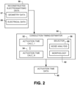
- FIG. 2 depicts an example of a dynamic activation time estimator 50 such as can utilize the conduction pattern estimator 20.
- the dynamic activation time estimator 50 can include a plurality of instances of activation time calculators 52 through 54 demonstrated at Activation Time Calc_1 through Activation Time Calc_N, where N positive integer greater than or equal to 2.
- the estimator 50 thus can employ any activation time calculator 52 through 54 to compute activation time for the plurality of signals demonstrated as reconstructed electroanatomic data 56.
- Each of the activation time calculators 52 through 54 can implement a different calculation function for computing activation times.
- one of the calculators is configured as the conduction pattern estimator 20 of FIG.
- reconstructed electroanatomic data 56 can be stored in memory and include both geometry data 57 and electrical data 59 for a cardiac envelope for which the signals have been reconstructed by solving the inverse problem based upon non-invasively measured electrical signals.
- the estimator 50 can employ a selected one of the activation time calculators 52 through 54 for computing the activation time for each of the respective segments.
- a common activation time calculator can be used for each of the signals or different activation time calculators can be used to compute the activation time for different segments of the same signal location for different time segments.
- the estimator 50 includes a selector 58 to select which of the activation time calculators 52 through 54 to utilize for computing the activation times for each given segment.
- the selector 58 can include a noise analysis component 60 and a morphology analysis component 62, which can be programmed to analyze noise and morphology, respectively, of each of the signals. If the selector 58 otherwise ascertains that the signal exhibits a significant amount of noise (e.g., greater than a predetermined noise threshold), the selector 58 can selectively apply an activation time calculator 52 to filter the signal and apply a zero crossing detector or a maximum derivative of the negative slope for the potential candidate segment to determine the activation time.
- the selector 58 can select a different activation time calculator 54. For example, where the selector components 60 and 62 determine that the downward sloping segment has a sufficient signal-to-noise ratio and exceeds a minimum threshold duration, the selector 58 can select one of the activation time calculators 52-54 corresponding to the conduction pattern estimator 20 disclosed with respect to FIG. 1 .
- the estimator 50 can in turn generate an activation time data 66 that is stored in memory and be associated with the reconstructed electroanatomic data by being indexed with respect time.
- FIG. 4 demonstrates another signal 76 in which a selected portion of the signal demonstrated within a dotted box 78 is enlarged.
- the enlarged portion of the signal demonstrates an example where the activation time is determined at the 50% of the downward sloping segment, indicated at 80. This is at one-half of the amplitude between the peak and the trough 82 of the signal.
- a portion of the signal segment before and after the identified activation time can be selected to visualize a pre-activation time window for 80% to 50% of the segment as well as a post-activation time window from 50% to 20% of the amplitude relative to the identified activation time at 80.
- These pre and post-activation time windows thus can be visualized on a graphical map as regions extending along opposing sides of the activation wave front pattern, such as shown in FIG. 6 .
- FIG. 5 is a flow diagram demonstrating an example method 90 to determine conduction patterns and conduction pattern parameters (activation times) for a plurality of electrophysiological signals (e.g., reconstructed electrograms). The method further can be implemented generate a corresponding output for visualization of one or more electrical characteristics of a patient's heart, including the conduction patterns and associated conduction pattern parameters.
- the method 90 begins at 92 in which electrograms (e.g., data 18, 56) are stored.
- the electrograms correspond to unipolar electrograms that have been reconstructed (e.g., by electrogram reconstruction 182) onto a cardiac envelope with respect to a patient's heart surface based on signals measured (e.g., by sensors 164) non-invasively across a patient's body, such as disclosed herein.
- signals are analyzed (e.g., by analyzer 24) to identify candidate signal segments. For example, morphology and amplitude of the signals can be analyzed to identify the candidate segments.
- the method 90 thus first finds all the downward slopes that can be potentially associated with activation, and then puts all these downward slopes into two categories: one group of downward slopes that are associated with sufficiently large amplitude and short durations (based on applying amplitude and morphology criteria) and are considered as exhibiting true activation activity; and the other group, where the amplitude is small or contain noise, is defined as questionable slopes that could either due to damaged (but still functional) heart tissue or due to noise or far-field sensing.
- the potential segments identified at 98 thus may define a set of questionable downward sloping segments requiring further analysis (e.g., by analyzer 24) at 100. For example, at 100, a determination is made whether each potential segment is spatially and temporally consistent with confident neighboring segments, namely those candidate segments identified at 96. That is, around a true activation at a particular location on the surface, there should be a neighboring activation happening at the same or similar time. In contrast, noise-associated slopes (due to its stochastic nature) are spatially isolated and therefore have low chance to have spatial continuity.
- a conduction pattern parameter (e.g., surrogate activation time parameter) can be identified (e.g., by conduction pattern identifier 32) for each candidate segment in the combined set of candidate segments.
- the conduction pattern parameter provides a surrogate activation time, such as 50% of the amplitude of the downward sloping segment, such as disclosed herein or another location that can be consistently applied to the downward sloping segments.
- an output can be generated to display.
- the output can include a sequence of activation snapshots in which the activation time can be displayed for different time indices, such as the graphical maps 120 shown in FIG. 6 .
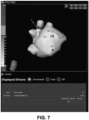
- the GUI can be activated in response to a user input to document user review of each indication of the arrhythmogenic activity (e.g., rotational and/or focal activity) displayed in the graphical map 134, 140 or the GUI somewhere else, more generally.
- the GUI can enable a user to remove a given indication of the arrhythmogenic activity displayed in the graphical map in response to a user input.
- a user can employ a user input device (e.g., mouse or touch screen interface) to reject one or more rotational activities or focal activities that are displayed on the map.
- the act of removal further can be tracked to document each instance of the user review and removal. Notes can also be provided and stored in memory if the user decides to document reasons for a decision to remove or retain the displayed indication of arrhythmogenic activity.
- FIG. 9 depicts an example of a system 150 that can be utilized for performing diagnostics and/or treatment of a patient.
- the system 150 can be implemented to generate corresponding maps for a patient's heart 152 in real time as part of a diagnostic procedure (e.g., an electrophysiology study) to help assess the electrical activity and identify arrhythmia drivers for the patient's heart.
- the system 150 can be utilized as part of a treatment procedure, such as to help a physician determine parameters for delivering a therapy to the patient (e.g., delivery location, amount and type of therapy) based on one or more identified arrhythmia drivers.
- a catheter such as a pacing or an ablation catheter, having one or more therapy delivery devices 156 affixed thereto can be inserted into a patient's body 154 as to contact the patient's heart 152, endocardially or epicardially.
- the placement of the therapy delivery device 156 can be guided according to the location of one or more arrhythmia drivers (e.g., stable rotational activity, foci, fast-firing locations or the like) that have been identified as disclosed herein.
- the guidance can be automated, semi-automated or be manually implemented based on information provided.
- the therapy device 156 can be configured to deliver electrical therapy, chemical therapy, sound wave therapy, thermal therapy or any combination thereof.
- the therapy delivery device 156 can include one or more electrodes located at a tip of an ablation catheter configured to generate heat for ablating tissue in response to electrical signals (e.g., radiofrequency energy) supplied by a therapy system 158.
- the therapy delivery device 156 can be configured to deliver cooling to perform ablation (e.g., cryogenic ablation), to deliver chemicals (e.g., drugs), ultrasound ablation, high-frequency ablation, or a combination of these or other therapy mechanisms.
- the therapy delivery device 156 can include one or more electrodes located at a tip of a pacing catheter to deliver electrical stimulation, such as for pacing the heart, in response to electrical signals (e.g., pacing pulses) supplied by a therapy system 158.
- electrical signals e.g., pacing pulses
- Other types of therapy can also be delivered via the therapy system 158 and the invasive therapy delivery device 156 that is positioned within the body.
- the therapy system 158 can be located external to the patient's body 154 and be configured to control therapy that is being delivered by the device 156.
- the therapy system 158 includes controls (e.g., hardware and/or software) 160 that can communicate (e.g., supply) electrical signals via a conductive link electrically connected between the delivery device (e.g., one or more electrodes) 156 and the therapy system 158.
- the control system 160 can control parameters of the signals supplied to the device 156 (e.g., current, voltage, repetition rate, trigger delay, sensing trigger amplitude) for delivering therapy (e.g., ablation or stimulation) via the electrode(s) 154 to one or more location of the heart 152.
- the control circuitry 160 can set the therapy parameters and apply stimulation based on automatic, manual (e.g., user input) or a combination of automatic and manual (e.g., semiautomatic) controls.
- One or more sensors can also communicate sensor information back to the therapy system 158.
- the position of the device 156 relative to the heart 152 can be determined and tracked intraoperatively via an imaging modality (e.g., fluoroscopy, x-ray), a mapping system 162, direct vision or the like. The location of the device 156 and the therapy parameters thus can be combined to determine corresponding therapy parameter data.
- an imaging modality e.g., fluoroscopy, x-ray
- mapping system 162 direct vision or the like.
- a sensor array 164 includes one or more electrodes that can be utilized for recording patient electrical activity.
- the sensor array 164 can correspond to a high-density arrangement of body surface sensors (e.g., greater than approximately 200 electrodes) that are distributed over a portion of the patient's torso for measuring electrical activity associated with the patient's heart (e.g., as part of an electrocardiographic mapping procedure).
- body surface sensors e.g., greater than approximately 200 electrodes
- An example of a non-invasive sensor array that can be used is shown and described in International application No. PCT/US2009/063803, filed 10 November 2009 .
- the array can be a reduced set of electrodes, which does not cover the patient's entire torso and is designed for measuring electrical activity for a particular purpose (e.g., an array of electrodes specially designed for analyzing AF and/or VF) and/or for monitoring a predetermined spatial region of the heart.
- One or more sensors may also be located on the device 156 that is inserted into the patient's body. Such sensors can be utilized separately or in conjunction with the non-invasive sensors 164 for mapping electrical activity for an endocardial surface, such as the wall of a heart chamber, as well as for an epicardial surface. Additionally, such electrode can also be utilized to help localize the device 156 within the heart 152, which can be registered into an image or map that is generated by the system 150. Alternatively, such localization can be implemented in the absence of emitting a signal from an electrode within or on the heart 152.
- the sensor array(s) 164 provide the sensed electrical information to a corresponding measurement system 166.
- the measurement system 166 can include appropriate controls and signal processing circuitry 168 for providing corresponding measurement data 170 that describes electrical activity detected by the sensors in the sensor array 164.
- the measurement data 170 can include analog and/or digital information (e.g., corresponding to electrical data 59).
- the control 168 can also be configured to control the data acquisition process (e.g., sample rate, line filtering) for measuring electrical activity and providing the measurement data 170.
- the control 168 can control acquisition of measurement data 170 separately from the therapy system operation, such as in response to a user input.
- the measurement data 170 can be acquired concurrently with and in synchronization with delivering therapy by the therapy system, such as to detect electrical activity of the heart 152 that occurs in response to applying a given therapy (e.g., according to therapy parameters).
- appropriate time stamps can be utilized for indexing the temporal relationship between the respective measurement data 170 and therapy parameters use to deliver therapy as to facilitate the evaluation and analysis thereof.
- the measurement system 166 can measure electrical activity of a predetermined region or the entire heart concurrently (e.g., where the sensor array 164 covers the entire thorax of the patient's body 154), the resulting output data (e.g., visualizing attributes of identified conduction patterns, such as rotational activity and/or other electrocardiographic maps) thus can also represent concurrent data for the predetermined region or the entire heart in a temporally and spatially consistent manner.
- the time interval for which the output data/maps are computed can be selected based on user input (e.g., selecting a timer interval from one or more waveforms). Additionally or alternatively, the selected intervals can be synchronized with the application of therapy by the therapy system 158.
- electrogram reconstruction 180 can be programmed to compute an inverse solution and provide corresponding reconstructed electrograms based on the process signals and the geometry data 172.
- the reconstructed electrograms thus can correspond to electrocardiographic activity across a cardiac envelope, and can include static (three-dimensional at a given instant in time) and/or be dynamic (e.g., four-dimensional map that varies over one or more time intervals).
- Examples of inverse algorithms that can be utilized in the system 10 include those disclosed in U.S. Patent Nos. 7,983,743 and 6,772,004 .
- the EGM reconstruction 180 thus can reconstruct the body surface electrical activity measured via the sensor array 164 onto a multitude of locations on a cardiac envelope (e.g., greater than 1000 locations, such as about 2000 locations or more).
- the mapping system 162 can compute electrical activity over a sub-region of the heart based on electrical activity measured invasively, such as via a basket catheter or other form of measurement probe.
- the geometry data 172 may be in the form of graphical representation of the patient's torso, such as image data acquired for the patient.
- image processing can include extraction and segmentation of anatomical features, including one or more organs and other structures, from a digital image set.
- a location for each of the electrodes in the sensor array 164 can be included in the patient geometry data 172, such as by acquiring the image while the electrodes are disposed on the patient and identifying the electrode locations in a coordinate system through appropriate extraction and segmentation.
- Other non-imaging based techniques can also be utilized to obtain the position of the electrodes in the sensor array, such as a digitizer or manual measurements.
- the geometry data 172 can correspond to a mathematical model, such as can be a generic model or a model that has been constructed based on image data for the patient.
- Appropriate anatomical or other landmarks, including locations for the electrodes in the sensor array 164 can be identified in the geometry data 172 to facilitate registration of the electrical measurement data 170 and performing the inverse method thereon. The identification of such landmarks can be done manually (e.g., by a person via image editing software) or automatically (e.g., via image processing techniques).
- the geometry data 172 can be acquired using nearly any imaging modality based on which a corresponding representation of the geometrical surface can be constructed, such as described herein. Such imaging may be performed concurrently with recording the electrical activity that is utilized to generate the patient measurement data 170 or the imaging can be performed separately (e.g., before or after the measurement data has been acquired).
- a conduction pattern estimator 182 can process one or more intervals of the electrogram data to determine activation time across the surface.
- the conduction pattern estimator 182 constitutes instructions, which can be implemented according to any of the approaches disclosed herein (see, e.g., FIGS. 1-6 and corresponding description), and thus can provide activation times for each of the plurality of signals represented by the electrogram data.
- the activation times can be aggregated with geometry data to provide output data 174 to a display 192 for visualizing a graphical activation map (see, e.g., FIG. 6 ) 194 depicting a wave front and propagation thereof across the heart surface based on the identified conduction patterns for such surface over one or more time intervals.
- the mapping system 162 is programmed to combine the measurement data 170 corresponding to electrical activity of the heart 152 with geometry data 172 (e.g., corresponding to geometry data 57) by applying appropriate processing and computations to provide corresponding output data 174.
- the output data 174 can include data provided to the display 192 for visualization of one or more graphical maps 194 and other related information to characterize one or more arrhythmia drivers, which can be localized or global drivers across the cardiac envelope (e.g., on a surface of the heart 152).
- the output generator (e.g., output engine 36) 186 can be programmed to generate graphic maps based on the computed output data, such as noted above. Parameters associated with the displayed graphical representation, corresponding to an output visualization of the computed map, such as including selecting a time interval, a type of information that is to be presented in the visualization and the like can be selected in response to a user input via a graphical user interface (GUI) 190.
- GUI graphical user interface
- a user can employ the GUI 190 to selectively program one or more parameters (e.g., temporal and spatial thresholds, filter parameters and the like) utilized by the arrhythmia driver analyzer method 182 and/or to select one or more sample time intervals to set a time duration for the electrical data 170 that is utilized by the mapping system 162.
- the mapping system 162 thus can generate corresponding output data 174 that can in turn be rendered by the output engine 186 as a corresponding graphical output in a display 192, such as including an electrocardiographic map 194.
- the map generator can generate maps and other output visualizations, such as including but not limited to the maps and other output visualizations disclosed herein.
- the output data 174 can be utilized by the therapy system 158.
- the control that is implemented can be fully automated control, semi-automated control (partially automated and responsive to a user input) or manual control based on the output data 174.
- the control 160 of the therapy system can utilize the output data 174 to control one or more therapy parameters.
- the control 160 can control delivery of ablation therapy to a site of the heart (e.g., epicardial or endocardial wall) based on activation timing or activation wave fronts determined by the conduction pattern estimator 182 and/or based on one or more arrhythmia drivers identified by the arrhythmia driver analyzer method 182.
- an individual can view the map 194 generated in the display to manually control the therapy system.
- Other types of therapy and devices can also be controlled based on the output data 174 and corresponding graphical map 194.
- the systems and methods herein (1) avoid signal distortion due to filtering, (2) use a new and more robust way to pick the activation time, (3) do not require phase calculation and is thus capable of analyzing data with shorter duration, and (4) enable a new and easy-to-understand visualization mode for the activation wave front.
- portions of the invention may be embodied as a method, data processing system, or computer program product, without deviating from the scope of the appended claims. Accordingly, these portions of the present invention may take the form of an entirely hardware embodiment, an entirely software embodiment, or an embodiment combining software and hardware. Furthermore, portions of the invention may be a computer program product on a computer-usable storage medium having computer readable program code on the medium. Any suitable computer-readable medium may be utilized including, but not limited to, static and dynamic storage devices, hard disks, optical storage devices, and magnetic storage devices.
Landscapes
- Health & Medical Sciences (AREA)
- Life Sciences & Earth Sciences (AREA)
- Engineering & Computer Science (AREA)
- Public Health (AREA)
- Medical Informatics (AREA)
- Biomedical Technology (AREA)
- General Health & Medical Sciences (AREA)
- Pathology (AREA)
- Biophysics (AREA)
- Heart & Thoracic Surgery (AREA)
- Physics & Mathematics (AREA)
- Molecular Biology (AREA)
- Surgery (AREA)
- Animal Behavior & Ethology (AREA)
- Veterinary Medicine (AREA)
- Cardiology (AREA)
- Signal Processing (AREA)
- Computer Vision & Pattern Recognition (AREA)
- Artificial Intelligence (AREA)
- Physiology (AREA)
- Psychiatry (AREA)
- Primary Health Care (AREA)
- Epidemiology (AREA)
- General Business, Economics & Management (AREA)
- Business, Economics & Management (AREA)
- Nuclear Medicine, Radiotherapy & Molecular Imaging (AREA)
- Human Computer Interaction (AREA)
- Radiology & Medical Imaging (AREA)
- Data Mining & Analysis (AREA)
- Databases & Information Systems (AREA)
- Measurement And Recording Of Electrical Phenomena And Electrical Characteristics Of The Living Body (AREA)
Claims (11)
- Procédé comprenant :
l'analyse, par un ou plusieurs processeurs (16), d'une morphologie et d'une amplitude de chacun d'une pluralité de signaux électrophysiologiques capturés par une pluralité de capteurs (164) répartis sur une surface du corps d'un patient pour identifier des segments candidats de chaque signal satisfaisant des critères de motif de conduction prédéterminés, l'analyse de la morphologie et de l'amplitude comprenant en outre la détermination, par le ou les processeurs (16), d'un ensemble de segments potentiels dans chacun d'un ensemble restant des formes d'onde de signal électrophysiologique, qui n'ont pas été identifiés en tant que segments candidats satisfaisant des critères de motif de conduction prédéterminés, la détermination de l'ensemble de segments potentiels comprenant en outre :la sélection, par le ou les processeurs (16), d'au moins une partie des segments candidats à partir de l'ensemble de segments potentiels sur la base de l'amplitude et de la durée de celui-ci satisfaisant des critères d'amplitude et de durée ; etla désignation, par le ou les processeurs (16), d'une autre partie de l'ensemble de segments potentiels pour une évaluation ultérieure, l'évaluation ultérieure comprenant :la sélection, par le ou les processeurs (16), en tant que l'un des segments candidats, de chaque segment dans l'ensemble de segments potentiels qui est spatialement et temporellement cohérent avec des formes d'onde de signal provenant de noeuds voisins qui ont été sélectionnés en tant que segments candidats et l'agrégation des segments candidats pour chacune parmi la pluralité de formes d'onde de signal électrophysiologique ; etl'élimination, par le ou les processeurs (16), de chaque segment respectif de la considération ultérieure en réponse à la détermination du paramètre de synchronisation de conduction qui n'est pas cohérent spatialement et/ou temporellement avec des formes d'onde de signal provenant de noeuds voisins qui ont été sélectionnés en tant que segments candidats ;la détermination, par le ou les processeurs (16), d'un paramètre de synchronisation de conduction pour chaque segment candidat dans chacun de la pluralité de signaux électrophysiologiques ; etle fait d'amener, par le ou les processeurs (16), une carte graphique (38) à être délivrée sur un affichage (12) qui comporte une visualisation ou dérivée sur la base des paramètres de synchronisation de conduction déterminés pour la pluralité de signaux électrophysiologiques. - Procédé selon la revendication 1, dans lequel le procédé comprend en outre :le calcul d'une indication d'activité arythmogène sur la base du paramètre de synchronisation de conduction ;la génération de la carte graphique (38) pour visualiser l'indication d'activité arythmogène par rapport au coeur (152) ; etla délivrance de la carte graphique (38) à un dispositif d'affichage (12).
- Procédé selon la revendication 2, dans lequel l'indication d'activité arythmogène comprend un nombre de points focaux, un nombre d'activités de rotation et/ou une trajectoire d'au moins une activité de rotation, l'indication d'activité arythmogène étant affichée dans la carte graphique (38) spatialement par rapport au coeur (152).
- Procédé selon la revendication 2 ou 3, comprenant en outre :l'élimination d'une indication donnée de l'activité arythmogène affichée dans la carte graphique (38) en réponse à une instruction d'entrée utilisateur pour rejeter l'indication donnée d'activité arythmogène ; etle stockage, dans la mémoire (14), de données relatives à l'utilisateur.
- Procédé selon l'une quelconque des revendications précédentes, mis en oeuvre en tant qu'instructions stockées dans un ou plusieurs supports non transitoires lisibles par ordinateur.
- Procédé selon l'une quelconque des revendications précédentes, comprenant en outre :l'acquisition de signaux électriques par un agencement non invasif de la pluralité de capteurs (164) répartis sur une surface corporelle externe du patient ; etle calcul des signaux électriques reconstruits sur une enveloppe cardiaque par rapport à une surface anatomique du coeur de patient (152) sur la base des signaux électriques acquis et des données géométriques décrivant des emplacements spatiaux de la pluralité de capteurs (164) par rapport à la géométrie du patient qui comporte la surface anatomique du coeur du patient (152).
- Système (10) comprenant :une mémoire (14) pour stocker des instructions et des données lisibles par machine, les données comprenant des données électriques (59) représentant des formes d'onde de signal électrophysiologique réparties sur une surface corporelle ;au moins un processeur (16) pour accéder à la mémoire (14) et exécuter les instructions, les instructions comprenant :
un estimateur de motif de conduction (20) qui analyse au moins une morphologie qui comporte une pente descendante de chacun d'une pluralité de signaux électrophysiologiques sur l'ensemble d'une surface du corps d'un patient, pour identifier des segments candidats de chacun de la pluralité de signaux électrophysiologiques qui satisfont des critères de motif de conduction prédéterminés, l'analyse de la morphologie comprenant en outre la détermination, par le ou les processeurs (16), d'un ensemble de segments potentiels dans chacun d'un ensemble restant des formes d'onde de signal électrophysiologique, qui n'ont pas été identifiés en tant que segments candidats satisfaisant des critères de motif de conduction prédéterminés, la détermination de l'ensemble de segments potentiels comprenant en outre :la sélection, par le ou les processeurs (16), d'au moins une partie des segments candidats à partir de l'ensemble de segments potentiels sur la base de la durée de ceux-ci satisfaisant des critères de durée ; etdésigner, par le ou les processeurs (16), une autre partie parmi l'ensemble de segments potentiels pour une évaluation ultérieure, sélectionner, en tant que segments candidats, chaque segment dans l'ensemble de segments potentiels qui est spatialement et temporellement cohérent avec des segments de signal provenant de noeuds voisins qui ont été sélectionnés en tant que segments candidats et l'agrégation des segments candidats pour chacune parmi la pluralité de formes d'onde de signal électrophysiologique ; etéliminer chaque segment respectif d'une considération ultérieure dans la détermination du paramètre de synchronisation de conduction qui n'est pas des segments de signal spatialement et/ou temporellement cohérents à partir de noeuds voisins qui ont été sélectionnés en tant que segments candidats ;un identifiant de paramètre de motif de conduction (32) qui détermine un paramètre de synchronisation de conduction pour chacun des segments candidats identifiés dans les formes d'onde de signal électrophysiologique ; etun moteur de sortie (36) qui fournit des données de sortie pour piloter un affichage avec une carte graphique (38) qui comporte une visualisation de, ou dérivée sur la base des paramètres de synchronisation de conduction déterminés pour les signaux électrophysiologiques. - Système (10) selon la revendication 7, dans lequel l'estimateur de motif de conduction (20) est en outre programmé pour :déterminer un ensemble de segments potentiels dans chacune des formes d'onde de signal électrophysiologique satisfaisant des critères de pente descendante ;sélectionner au moins une partie des segments candidats à partir de l'ensemble de segments potentiels sur la base d'une amplitude et d'une durée de ceux-ci satisfaisant des critères d'amplitude et de durée ; etdésigner une autre partie de l'ensemble de segments potentiels en tant que segments candidats douteux pour une évaluation ultérieure.
- Système (10) selon l'une quelconque des revendications 7 à 8,dans lequel le paramètre de synchronisation de conduction est un paramètre de temps d'activation représentant un temps d'activation identifié sur la pente descendante de chacun des segments candidats,le système comprenant en outre un estimateur de temps d'activation dynamique (50) qui sélectionne l'une d'une pluralité de fonctions de calcul de temps d'activation différentes sur la base d'au moins l'un parmi un bruit, une amplitude et la morphologie des formes d'onde de signal électrophysiologique, l'une sélectionnée parmi les fonctions de calcul de temps d'activation analysant les segments de signal pour identifier les segments candidats ; etl'estimateur de motif de conduction (20) comportant un analyseur de segment de signal (24) qui emploie la fonction de calcul de temps d'activation sélectionnée pour déterminer le temps d'activation pour chacune des formes d'onde de signal électrophysiologique.
- Système (10) selon l'une quelconque des revendications 7 à 9, comprenant en outre :un calculateur d'activité arythmogène (34) qui calcule une indication d'activité arythmogène sur la base du paramètre de synchronisation de conduction déterminé pour les formes d'onde de signal électrophysiologique, le moteur de sortie (36) générant la carte graphique (38) permettant de visualiser l'indication d'activité arythmogène par rapport au coeur (152) ; et/ouune interface utilisateur (190) qui stocke des données utilisateur dans la mémoire (14) pour documenter l'examen d'utilisateur de chaque indication de l'activité arythmogène affichée dans la carte graphique (38) en réponse à une entrée utilisateur correspondante interagissant avec l'indication affichée d'activité arythmogène, l'interface utilisateur (190) modifiant les données utilisateur stockées pour éliminer une indication donnée de l'activité arythmogène affichée dans la carte graphique (38) en réponse à une instruction d'entrée utilisateur pour rejeter l'indication donnée d'activité arythmogène ; et/ouun détecteur de segment de signal (22) qui détermine une pente et des pics pour chacune de la pluralité de formes d'onde de signal électrophysiologique, le détecteur de segment de signal (22) identifiant des segments de signal à pente descendante sur la base de la pente et des pics déterminés.
- Système (10) selon l'une quelconque des revendications 7 à 10, comprenant en outre :un agencement non invasif de capteurs (164) répartis sur une surface corporelle externe du patient pour acquérir des signaux électriques provenant d'une pluralité d'emplacements sur la surface corporelle externe ; etle calcul des signaux électriques reconstruits sur une enveloppe cardiaque par rapport à une surface anatomique du coeur (152) sur la base des signaux électriques et des données géométriques acquis décrivant des emplacements spatiaux des capteurs (164) par rapport à la géométrie du patient qui comporte la surface anatomique du coeur (152), les signaux électriques reconstruits étant stockés dans la mémoire (14) en tant que pluralité de formes d'onde de signal électrophysiologique.
Applications Claiming Priority (2)
| Application Number | Priority Date | Filing Date | Title |
|---|---|---|---|
| US201662331116P | 2016-05-03 | 2016-05-03 | |
| PCT/US2017/029267 WO2017192294A1 (fr) | 2016-05-03 | 2017-04-25 | Détection de synchronisation de conduction |
Publications (2)
| Publication Number | Publication Date |
|---|---|
| EP3451904A1 EP3451904A1 (fr) | 2019-03-13 |
| EP3451904B1 true EP3451904B1 (fr) | 2023-12-20 |
Family
ID=58669020
Family Applications (1)
| Application Number | Title | Priority Date | Filing Date |
|---|---|---|---|
| EP17721304.8A Active EP3451904B1 (fr) | 2016-05-03 | 2017-04-25 | Détection de synchronisation de conduction |
Country Status (4)
| Country | Link |
|---|---|
| US (2) | US10575749B2 (fr) |
| EP (1) | EP3451904B1 (fr) |
| CN (1) | CN109069002B (fr) |
| WO (1) | WO2017192294A1 (fr) |
Families Citing this family (22)
| Publication number | Priority date | Publication date | Assignee | Title |
|---|---|---|---|---|
| WO2019105986A1 (fr) * | 2017-11-29 | 2019-06-06 | Universiteit Gent | Détection d'activité de rotation en électrophysiologie cardiaque |
| US11229392B2 (en) * | 2018-03-15 | 2022-01-25 | Cardioinsight Technologies, Inc. | Detection and localization of cardiac fast firing |
| US11138792B2 (en) * | 2018-04-02 | 2021-10-05 | Cardioinsight Technologies, Inc. | Multi-dimensional method of fundamental solutions for reconstruction of electrophysiological activity |
| US11622732B2 (en) | 2018-04-26 | 2023-04-11 | Vektor Medical, Inc. | Identifying an attribute of an electromagnetic source configuration by matching simulated and patient data |
| US11065060B2 (en) * | 2018-04-26 | 2021-07-20 | Vektor Medical, Inc. | Identify ablation pattern for use in an ablation |
| US11259871B2 (en) | 2018-04-26 | 2022-03-01 | Vektor Medical, Inc. | Identify ablation pattern for use in an ablation |
| AU2019379084B2 (en) | 2018-11-13 | 2024-06-27 | Vektor Medical, Inc. | Augmentation of images with source locations |
| US11504046B2 (en) * | 2018-11-19 | 2022-11-22 | Cardioinsight Technologies, Inc. | Graph total variation for ECGI |
| WO2020242940A1 (fr) * | 2019-05-24 | 2020-12-03 | St. Jude Medical, Cardiology Division, Inc. | Système et procédé de cartographie cardiaque |
| US10595736B1 (en) | 2019-06-10 | 2020-03-24 | Vektor Medical, Inc. | Heart graphic display system |
| US10709347B1 (en) | 2019-06-10 | 2020-07-14 | Vektor Medical, Inc. | Heart graphic display system |
| US10687765B1 (en) * | 2019-09-24 | 2020-06-23 | Biosense Webster (Israel) Ltd. | Graphical user interface for parallel electroanatomical mappings |
| US11278233B2 (en) * | 2019-11-15 | 2022-03-22 | Biosense Webster (Israel) Ltd. | Method and apparatus to find abnormal activations in intra-cardiac electrocardiograms based on specificity and sensitivity |
| US11974853B2 (en) | 2020-10-30 | 2024-05-07 | Vektor Medical, Inc. | Heart graphic display system |
| US12383184B2 (en) | 2021-03-12 | 2025-08-12 | Cardioinsight Technologies Inc. | Late activation of cardiac signals |
| US11338131B1 (en) | 2021-05-05 | 2022-05-24 | Vektor Medical, Inc. | Guiding implantation of an energy delivery component in a body |
| US12390142B2 (en) | 2021-08-02 | 2025-08-19 | Cardioinsight Technologies Inc. | Systems and methods for electrocardiographic mapping and target site identification |
| WO2023014637A1 (fr) * | 2021-08-02 | 2023-02-09 | Cardioinsight Technologies Inc. | Systèmes et procédés de cartographie électrocardiographique et d'identification de site cible |
| CA3228337A1 (fr) | 2021-08-09 | 2023-02-16 | Vektor Medical, Inc. | Systeme d'affichage graphique d'etat tissulaire |
| US11534224B1 (en) | 2021-12-02 | 2022-12-27 | Vektor Medical, Inc. | Interactive ablation workflow system |
| US12526434B2 (en) | 2022-05-27 | 2026-01-13 | The Vektor Group, Inc. | Encoding electrocardiographic data |
| CN119562788A (zh) * | 2022-07-19 | 2025-03-04 | 科迪影技术股份有限公司 | 从电生理学信息中去除远场信号 |
Citations (2)
| Publication number | Priority date | Publication date | Assignee | Title |
|---|---|---|---|---|
| WO2010054409A1 (fr) * | 2008-11-10 | 2010-05-14 | Cardioinsight Technologies, Inc. | Visualisation de données électrophysiologiques |
| US20120283587A1 (en) * | 2011-05-03 | 2012-11-08 | Medtronic, Inc. | Assessing intra-cardiac activation patterns and electrical dyssynchrony |
Family Cites Families (17)
| Publication number | Priority date | Publication date | Assignee | Title |
|---|---|---|---|---|
| WO1999006112A1 (fr) | 1997-07-31 | 1999-02-11 | Case Western Reserve University | Systeme electrophysiologique de cartographie cardiaque base sur un catheter miniature sans contact non extensible a electrodes multiples et procede correspondant |
| WO2007013994A2 (fr) | 2005-07-22 | 2007-02-01 | Case Western Reserve University | Systeme et procede d'imagerie electrocardiographique non invasive |
| AU2009221694B2 (en) * | 2008-03-07 | 2013-09-26 | Cameron Health, Inc. | Accurate cardiac event detection in an implantable cardiac stimulus device |
| US10398326B2 (en) * | 2013-03-15 | 2019-09-03 | The Regents Of The University Of California | System and method of identifying sources associated with biological rhythm disorders |
| US9271680B2 (en) * | 2010-09-17 | 2016-03-01 | Cardioinsight Technologies, Inc. | System and methods for computing activation maps |
| US8948837B2 (en) * | 2011-01-13 | 2015-02-03 | Rhythmia Medical, Inc. | Electroanatomical mapping |
| US20120215117A1 (en) * | 2011-02-23 | 2012-08-23 | Pacesetter, Inc. | Systems and methods for estimating central arterial blood pressure of a patient |
| EP2765902B1 (fr) | 2011-10-12 | 2019-08-14 | CardioInsight Technologies, Inc. | Zone de détection pour une information électrique pertinente dans l'espace |
| US9381362B2 (en) * | 2012-01-20 | 2016-07-05 | Medtronic, Inc. | Modifying atrioventricular delay based on activation times |
| US8897863B2 (en) * | 2012-05-03 | 2014-11-25 | University Of Washington Through Its Center For Commercialization | Arrhythmia detection using hidden regularity to improve specificity |
| EP2945531B1 (fr) | 2013-01-17 | 2019-09-04 | CardioInsight Technologies, Inc. | Identification et mappage de point focal |
| CN105142508B (zh) | 2013-01-17 | 2018-04-06 | 科迪影技术股份有限公司 | 电生理信号的波前检测 |
| US9031642B2 (en) * | 2013-02-21 | 2015-05-12 | Medtronic, Inc. | Methods for simultaneous cardiac substrate mapping using spatial correlation maps between neighboring unipolar electrograms |
| WO2014182965A1 (fr) | 2013-05-08 | 2014-11-13 | Cardioinsight Technologies, Inc. | Analyse et détection pour entrainements arythmiques |
| US10098557B2 (en) * | 2013-11-18 | 2018-10-16 | Regents Of The University Of Minnesota | System and method for temporal sparse promoting imaging of cardiac activation |
| US9380953B2 (en) * | 2014-01-29 | 2016-07-05 | Biosense Webster (Israel) Ltd. | Hybrid bipolar/unipolar detection of activation wavefront |
| WO2015120064A1 (fr) * | 2014-02-04 | 2015-08-13 | Cardioinsight Technologies, Inc. | Analyse intégrée de données électrophysiologiques |
-
2017
- 2017-04-25 EP EP17721304.8A patent/EP3451904B1/fr active Active
- 2017-04-25 WO PCT/US2017/029267 patent/WO2017192294A1/fr not_active Ceased
- 2017-04-25 CN CN201780027368.9A patent/CN109069002B/zh active Active
- 2017-04-27 US US15/498,662 patent/US10575749B2/en active Active
-
2020
- 2020-01-28 US US16/774,662 patent/US11284830B2/en active Active
Patent Citations (2)
| Publication number | Priority date | Publication date | Assignee | Title |
|---|---|---|---|---|
| WO2010054409A1 (fr) * | 2008-11-10 | 2010-05-14 | Cardioinsight Technologies, Inc. | Visualisation de données électrophysiologiques |
| US20120283587A1 (en) * | 2011-05-03 | 2012-11-08 | Medtronic, Inc. | Assessing intra-cardiac activation patterns and electrical dyssynchrony |
Also Published As
| Publication number | Publication date |
|---|---|
| US20170319089A1 (en) | 2017-11-09 |
| US20200163570A1 (en) | 2020-05-28 |
| US11284830B2 (en) | 2022-03-29 |
| WO2017192294A1 (fr) | 2017-11-09 |
| EP3451904A1 (fr) | 2019-03-13 |
| CN109069002A (zh) | 2018-12-21 |
| US10575749B2 (en) | 2020-03-03 |
| CN109069002B (zh) | 2021-11-05 |
Similar Documents
| Publication | Publication Date | Title |
|---|---|---|
| US11284830B2 (en) | Detecting conduction timing | |
| CA2885531C (fr) | Mappage physiologique pour l'arythmie | |
| US10004413B2 (en) | Signal analysis related to treatment sites | |
| EP2945530B1 (fr) | Cartographie composite de points singuliers | |
| EP2994044B1 (fr) | Analyse et détection pour entrainements arythmiques | |
| US9974462B2 (en) | Signal characterization for detecting and/or analyzing driver activity | |
| EP2945531B1 (fr) | Identification et mappage de point focal | |
| EP3787492B1 (fr) | Détection de régions présentant une activité électrophysiologique irrégulière | |
| WO2018208896A1 (fr) | Mise en correspondance de motif et de vitesse de conduction | |
| EP3614913B1 (fr) | Analyse de connectivité de facteurs d'arythmie | |
| WO2025181580A1 (fr) | Analyse de signaux électrophysiologiques ectopiques |
Legal Events
| Date | Code | Title | Description |
|---|---|---|---|
| STAA | Information on the status of an ep patent application or granted ep patent |
Free format text: STATUS: UNKNOWN |
|
| STAA | Information on the status of an ep patent application or granted ep patent |
Free format text: STATUS: THE INTERNATIONAL PUBLICATION HAS BEEN MADE |
|
| PUAI | Public reference made under article 153(3) epc to a published international application that has entered the european phase |
Free format text: ORIGINAL CODE: 0009012 |
|
| STAA | Information on the status of an ep patent application or granted ep patent |
Free format text: STATUS: REQUEST FOR EXAMINATION WAS MADE |
|
| 17P | Request for examination filed |
Effective date: 20181130 |
|
| AK | Designated contracting states |
Kind code of ref document: A1 Designated state(s): AL AT BE BG CH CY CZ DE DK EE ES FI FR GB GR HR HU IE IS IT LI LT LU LV MC MK MT NL NO PL PT RO RS SE SI SK SM TR |
|
| AX | Request for extension of the european patent |
Extension state: BA ME |
|
| DAV | Request for validation of the european patent (deleted) | ||
| DAX | Request for extension of the european patent (deleted) | ||
| STAA | Information on the status of an ep patent application or granted ep patent |
Free format text: STATUS: EXAMINATION IS IN PROGRESS |
|
| 17Q | First examination report despatched |
Effective date: 20201216 |
|
| RIC1 | Information provided on ipc code assigned before grant |
Ipc: A61B 5/367 20210101ALI20230418BHEP Ipc: A61B 5/316 20210101ALI20230418BHEP Ipc: A61B 5/282 20210101ALI20230418BHEP Ipc: G16H 50/30 20180101ALI20230418BHEP Ipc: G16H 40/63 20180101ALI20230418BHEP Ipc: A61B 5/00 20060101AFI20230418BHEP |
|
| GRAP | Despatch of communication of intention to grant a patent |
Free format text: ORIGINAL CODE: EPIDOSNIGR1 |
|
| STAA | Information on the status of an ep patent application or granted ep patent |
Free format text: STATUS: GRANT OF PATENT IS INTENDED |
|
| INTG | Intention to grant announced |
Effective date: 20230818 |
|
| GRAS | Grant fee paid |
Free format text: ORIGINAL CODE: EPIDOSNIGR3 |
|
| GRAA | (expected) grant |
Free format text: ORIGINAL CODE: 0009210 |
|
| STAA | Information on the status of an ep patent application or granted ep patent |
Free format text: STATUS: THE PATENT HAS BEEN GRANTED |
|
| AK | Designated contracting states |
Kind code of ref document: B1 Designated state(s): AL AT BE BG CH CY CZ DE DK EE ES FI FR GB GR HR HU IE IS IT LI LT LU LV MC MK MT NL NO PL PT RO RS SE SI SK SM TR |
|
| REG | Reference to a national code |
Ref country code: GB Ref legal event code: FG4D |
|
| REG | Reference to a national code |
Ref country code: CH Ref legal event code: EP |
|
| REG | Reference to a national code |
Ref country code: DE Ref legal event code: R096 Ref document number: 602017077676 Country of ref document: DE |
|
| REG | Reference to a national code |
Ref country code: IE Ref legal event code: FG4D |
|
| PG25 | Lapsed in a contracting state [announced via postgrant information from national office to epo] |
Ref country code: GR Free format text: LAPSE BECAUSE OF FAILURE TO SUBMIT A TRANSLATION OF THE DESCRIPTION OR TO PAY THE FEE WITHIN THE PRESCRIBED TIME-LIMIT Effective date: 20240321 |
|
| REG | Reference to a national code |
Ref country code: LT Ref legal event code: MG9D |
|
| PG25 | Lapsed in a contracting state [announced via postgrant information from national office to epo] |
Ref country code: LT Free format text: LAPSE BECAUSE OF FAILURE TO SUBMIT A TRANSLATION OF THE DESCRIPTION OR TO PAY THE FEE WITHIN THE PRESCRIBED TIME-LIMIT Effective date: 20231220 |
|
| REG | Reference to a national code |
Ref country code: NL Ref legal event code: MP Effective date: 20231220 |
|
| PG25 | Lapsed in a contracting state [announced via postgrant information from national office to epo] |
Ref country code: ES Free format text: LAPSE BECAUSE OF FAILURE TO SUBMIT A TRANSLATION OF THE DESCRIPTION OR TO PAY THE FEE WITHIN THE PRESCRIBED TIME-LIMIT Effective date: 20231220 |
|
| PG25 | Lapsed in a contracting state [announced via postgrant information from national office to epo] |
Ref country code: LT Free format text: LAPSE BECAUSE OF FAILURE TO SUBMIT A TRANSLATION OF THE DESCRIPTION OR TO PAY THE FEE WITHIN THE PRESCRIBED TIME-LIMIT Effective date: 20231220 Ref country code: GR Free format text: LAPSE BECAUSE OF FAILURE TO SUBMIT A TRANSLATION OF THE DESCRIPTION OR TO PAY THE FEE WITHIN THE PRESCRIBED TIME-LIMIT Effective date: 20240321 Ref country code: FI Free format text: LAPSE BECAUSE OF FAILURE TO SUBMIT A TRANSLATION OF THE DESCRIPTION OR TO PAY THE FEE WITHIN THE PRESCRIBED TIME-LIMIT Effective date: 20231220 Ref country code: ES Free format text: LAPSE BECAUSE OF FAILURE TO SUBMIT A TRANSLATION OF THE DESCRIPTION OR TO PAY THE FEE WITHIN THE PRESCRIBED TIME-LIMIT Effective date: 20231220 Ref country code: BG Free format text: LAPSE BECAUSE OF FAILURE TO SUBMIT A TRANSLATION OF THE DESCRIPTION OR TO PAY THE FEE WITHIN THE PRESCRIBED TIME-LIMIT Effective date: 20240320 |
|
| REG | Reference to a national code |
Ref country code: AT Ref legal event code: MK05 Ref document number: 1641735 Country of ref document: AT Kind code of ref document: T Effective date: 20231220 |
|
| PG25 | Lapsed in a contracting state [announced via postgrant information from national office to epo] |
Ref country code: NL Free format text: LAPSE BECAUSE OF FAILURE TO SUBMIT A TRANSLATION OF THE DESCRIPTION OR TO PAY THE FEE WITHIN THE PRESCRIBED TIME-LIMIT Effective date: 20231220 |
|
| PG25 | Lapsed in a contracting state [announced via postgrant information from national office to epo] |
Ref country code: SE Free format text: LAPSE BECAUSE OF FAILURE TO SUBMIT A TRANSLATION OF THE DESCRIPTION OR TO PAY THE FEE WITHIN THE PRESCRIBED TIME-LIMIT Effective date: 20231220 Ref country code: RS Free format text: LAPSE BECAUSE OF FAILURE TO SUBMIT A TRANSLATION OF THE DESCRIPTION OR TO PAY THE FEE WITHIN THE PRESCRIBED TIME-LIMIT Effective date: 20231220 Ref country code: NO Free format text: LAPSE BECAUSE OF FAILURE TO SUBMIT A TRANSLATION OF THE DESCRIPTION OR TO PAY THE FEE WITHIN THE PRESCRIBED TIME-LIMIT Effective date: 20240320 Ref country code: NL Free format text: LAPSE BECAUSE OF FAILURE TO SUBMIT A TRANSLATION OF THE DESCRIPTION OR TO PAY THE FEE WITHIN THE PRESCRIBED TIME-LIMIT Effective date: 20231220 Ref country code: LV Free format text: LAPSE BECAUSE OF FAILURE TO SUBMIT A TRANSLATION OF THE DESCRIPTION OR TO PAY THE FEE WITHIN THE PRESCRIBED TIME-LIMIT Effective date: 20231220 Ref country code: HR Free format text: LAPSE BECAUSE OF FAILURE TO SUBMIT A TRANSLATION OF THE DESCRIPTION OR TO PAY THE FEE WITHIN THE PRESCRIBED TIME-LIMIT Effective date: 20231220 |
|
| PG25 | Lapsed in a contracting state [announced via postgrant information from national office to epo] |
Ref country code: IS Free format text: LAPSE BECAUSE OF FAILURE TO SUBMIT A TRANSLATION OF THE DESCRIPTION OR TO PAY THE FEE WITHIN THE PRESCRIBED TIME-LIMIT Effective date: 20240420 |
|
| PG25 | Lapsed in a contracting state [announced via postgrant information from national office to epo] |
Ref country code: CZ Free format text: LAPSE BECAUSE OF FAILURE TO SUBMIT A TRANSLATION OF THE DESCRIPTION OR TO PAY THE FEE WITHIN THE PRESCRIBED TIME-LIMIT Effective date: 20231220 Ref country code: AT Free format text: LAPSE BECAUSE OF FAILURE TO SUBMIT A TRANSLATION OF THE DESCRIPTION OR TO PAY THE FEE WITHIN THE PRESCRIBED TIME-LIMIT Effective date: 20231220 |
|
| PG25 | Lapsed in a contracting state [announced via postgrant information from national office to epo] |
Ref country code: SK Free format text: LAPSE BECAUSE OF FAILURE TO SUBMIT A TRANSLATION OF THE DESCRIPTION OR TO PAY THE FEE WITHIN THE PRESCRIBED TIME-LIMIT Effective date: 20231220 |
|
| PG25 | Lapsed in a contracting state [announced via postgrant information from national office to epo] |
Ref country code: SM Free format text: LAPSE BECAUSE OF FAILURE TO SUBMIT A TRANSLATION OF THE DESCRIPTION OR TO PAY THE FEE WITHIN THE PRESCRIBED TIME-LIMIT Effective date: 20231220 Ref country code: SK Free format text: LAPSE BECAUSE OF FAILURE TO SUBMIT A TRANSLATION OF THE DESCRIPTION OR TO PAY THE FEE WITHIN THE PRESCRIBED TIME-LIMIT Effective date: 20231220 Ref country code: RO Free format text: LAPSE BECAUSE OF FAILURE TO SUBMIT A TRANSLATION OF THE DESCRIPTION OR TO PAY THE FEE WITHIN THE PRESCRIBED TIME-LIMIT Effective date: 20231220 Ref country code: IT Free format text: LAPSE BECAUSE OF FAILURE TO SUBMIT A TRANSLATION OF THE DESCRIPTION OR TO PAY THE FEE WITHIN THE PRESCRIBED TIME-LIMIT Effective date: 20231220 Ref country code: IS Free format text: LAPSE BECAUSE OF FAILURE TO SUBMIT A TRANSLATION OF THE DESCRIPTION OR TO PAY THE FEE WITHIN THE PRESCRIBED TIME-LIMIT Effective date: 20240420 Ref country code: EE Free format text: LAPSE BECAUSE OF FAILURE TO SUBMIT A TRANSLATION OF THE DESCRIPTION OR TO PAY THE FEE WITHIN THE PRESCRIBED TIME-LIMIT Effective date: 20231220 Ref country code: CZ Free format text: LAPSE BECAUSE OF FAILURE TO SUBMIT A TRANSLATION OF THE DESCRIPTION OR TO PAY THE FEE WITHIN THE PRESCRIBED TIME-LIMIT Effective date: 20231220 Ref country code: AT Free format text: LAPSE BECAUSE OF FAILURE TO SUBMIT A TRANSLATION OF THE DESCRIPTION OR TO PAY THE FEE WITHIN THE PRESCRIBED TIME-LIMIT Effective date: 20231220 |
|
| PG25 | Lapsed in a contracting state [announced via postgrant information from national office to epo] |
Ref country code: PL Free format text: LAPSE BECAUSE OF FAILURE TO SUBMIT A TRANSLATION OF THE DESCRIPTION OR TO PAY THE FEE WITHIN THE PRESCRIBED TIME-LIMIT Effective date: 20231220 Ref country code: PT Free format text: LAPSE BECAUSE OF FAILURE TO SUBMIT A TRANSLATION OF THE DESCRIPTION OR TO PAY THE FEE WITHIN THE PRESCRIBED TIME-LIMIT Effective date: 20240422 |
|
| PG25 | Lapsed in a contracting state [announced via postgrant information from national office to epo] |
Ref country code: PT Free format text: LAPSE BECAUSE OF FAILURE TO SUBMIT A TRANSLATION OF THE DESCRIPTION OR TO PAY THE FEE WITHIN THE PRESCRIBED TIME-LIMIT Effective date: 20240422 Ref country code: PL Free format text: LAPSE BECAUSE OF FAILURE TO SUBMIT A TRANSLATION OF THE DESCRIPTION OR TO PAY THE FEE WITHIN THE PRESCRIBED TIME-LIMIT Effective date: 20231220 |
|
| REG | Reference to a national code |
Ref country code: DE Ref legal event code: R097 Ref document number: 602017077676 Country of ref document: DE |
|
| PG25 | Lapsed in a contracting state [announced via postgrant information from national office to epo] |
Ref country code: DK Free format text: LAPSE BECAUSE OF FAILURE TO SUBMIT A TRANSLATION OF THE DESCRIPTION OR TO PAY THE FEE WITHIN THE PRESCRIBED TIME-LIMIT Effective date: 20231220 |
|
| PLBE | No opposition filed within time limit |
Free format text: ORIGINAL CODE: 0009261 |
|
| STAA | Information on the status of an ep patent application or granted ep patent |
Free format text: STATUS: NO OPPOSITION FILED WITHIN TIME LIMIT |
|
| PG25 | Lapsed in a contracting state [announced via postgrant information from national office to epo] |
Ref country code: SI Free format text: LAPSE BECAUSE OF FAILURE TO SUBMIT A TRANSLATION OF THE DESCRIPTION OR TO PAY THE FEE WITHIN THE PRESCRIBED TIME-LIMIT Effective date: 20231220 |
|
| PG25 | Lapsed in a contracting state [announced via postgrant information from national office to epo] |
Ref country code: SI Free format text: LAPSE BECAUSE OF FAILURE TO SUBMIT A TRANSLATION OF THE DESCRIPTION OR TO PAY THE FEE WITHIN THE PRESCRIBED TIME-LIMIT Effective date: 20231220 Ref country code: DK Free format text: LAPSE BECAUSE OF FAILURE TO SUBMIT A TRANSLATION OF THE DESCRIPTION OR TO PAY THE FEE WITHIN THE PRESCRIBED TIME-LIMIT Effective date: 20231220 |
|
| PG25 | Lapsed in a contracting state [announced via postgrant information from national office to epo] |
Ref country code: MC Free format text: LAPSE BECAUSE OF FAILURE TO SUBMIT A TRANSLATION OF THE DESCRIPTION OR TO PAY THE FEE WITHIN THE PRESCRIBED TIME-LIMIT Effective date: 20231220 |
|
| 26N | No opposition filed |
Effective date: 20240923 |
|
| PG25 | Lapsed in a contracting state [announced via postgrant information from national office to epo] |
Ref country code: MC Free format text: LAPSE BECAUSE OF FAILURE TO SUBMIT A TRANSLATION OF THE DESCRIPTION OR TO PAY THE FEE WITHIN THE PRESCRIBED TIME-LIMIT Effective date: 20231220 |
|
| REG | Reference to a national code |
Ref country code: CH Ref legal event code: PL |
|
| PG25 | Lapsed in a contracting state [announced via postgrant information from national office to epo] |
Ref country code: LU Free format text: LAPSE BECAUSE OF NON-PAYMENT OF DUE FEES Effective date: 20240425 |
|
| GBPC | Gb: european patent ceased through non-payment of renewal fee |
Effective date: 20240425 |
|
| REG | Reference to a national code |
Ref country code: BE Ref legal event code: MM Effective date: 20240430 |
|
| PG25 | Lapsed in a contracting state [announced via postgrant information from national office to epo] |
Ref country code: LU Free format text: LAPSE BECAUSE OF NON-PAYMENT OF DUE FEES Effective date: 20240425 |
|
| PG25 | Lapsed in a contracting state [announced via postgrant information from national office to epo] |
Ref country code: BE Free format text: LAPSE BECAUSE OF NON-PAYMENT OF DUE FEES Effective date: 20240430 |
|
| PG25 | Lapsed in a contracting state [announced via postgrant information from national office to epo] |
Ref country code: GB Free format text: LAPSE BECAUSE OF NON-PAYMENT OF DUE FEES Effective date: 20240425 |
|
| PG25 | Lapsed in a contracting state [announced via postgrant information from national office to epo] |
Ref country code: GB Free format text: LAPSE BECAUSE OF NON-PAYMENT OF DUE FEES Effective date: 20240425 Ref country code: BE Free format text: LAPSE BECAUSE OF NON-PAYMENT OF DUE FEES Effective date: 20240430 Ref country code: CH Free format text: LAPSE BECAUSE OF NON-PAYMENT OF DUE FEES Effective date: 20240430 |
|
| PG25 | Lapsed in a contracting state [announced via postgrant information from national office to epo] |
Ref country code: IE Free format text: LAPSE BECAUSE OF NON-PAYMENT OF DUE FEES Effective date: 20240425 |
|
| PGFP | Annual fee paid to national office [announced via postgrant information from national office to epo] |
Ref country code: DE Payment date: 20250319 Year of fee payment: 9 |
|
| PG25 | Lapsed in a contracting state [announced via postgrant information from national office to epo] |
Ref country code: CY Free format text: LAPSE BECAUSE OF FAILURE TO SUBMIT A TRANSLATION OF THE DESCRIPTION OR TO PAY THE FEE WITHIN THE PRESCRIBED TIME-LIMIT; INVALID AB INITIO Effective date: 20170425 |
|
| PG25 | Lapsed in a contracting state [announced via postgrant information from national office to epo] |
Ref country code: HU Free format text: LAPSE BECAUSE OF FAILURE TO SUBMIT A TRANSLATION OF THE DESCRIPTION OR TO PAY THE FEE WITHIN THE PRESCRIBED TIME-LIMIT; INVALID AB INITIO Effective date: 20170425 |
|
| PGFP | Annual fee paid to national office [announced via postgrant information from national office to epo] |
Ref country code: FR Payment date: 20260320 Year of fee payment: 10 |