EP3452632B1 - Procédé de régulation de température de pompe électromagnétique - Google Patents
Procédé de régulation de température de pompe électromagnétique Download PDFInfo
- Publication number
- EP3452632B1 EP3452632B1 EP17720141.5A EP17720141A EP3452632B1 EP 3452632 B1 EP3452632 B1 EP 3452632B1 EP 17720141 A EP17720141 A EP 17720141A EP 3452632 B1 EP3452632 B1 EP 3452632B1
- Authority
- EP
- European Patent Office
- Prior art keywords
- electromagnetic pump
- liquid metal
- feed tube
- container
- current
- Prior art date
- Legal status (The legal status is an assumption and is not a legal conclusion. Google has not performed a legal analysis and makes no representation as to the accuracy of the status listed.)
- Not-in-force
Links
Images


Classifications
-
- F—MECHANICAL ENGINEERING; LIGHTING; HEATING; WEAPONS; BLASTING
- F04—POSITIVE - DISPLACEMENT MACHINES FOR LIQUIDS; PUMPS FOR LIQUIDS OR ELASTIC FLUIDS
- F04B—POSITIVE-DISPLACEMENT MACHINES FOR LIQUIDS; PUMPS
- F04B49/00—Control, e.g. of pump delivery, or pump pressure of, or safety measures for, machines, pumps, or pumping installations, not otherwise provided for, or of interest apart from, groups F04B1/00 - F04B47/00
- F04B49/06—Control using electricity
-
- C—CHEMISTRY; METALLURGY
- C23—COATING METALLIC MATERIAL; COATING MATERIAL WITH METALLIC MATERIAL; CHEMICAL SURFACE TREATMENT; DIFFUSION TREATMENT OF METALLIC MATERIAL; COATING BY VACUUM EVAPORATION, BY SPUTTERING, BY ION IMPLANTATION OR BY CHEMICAL VAPOUR DEPOSITION, IN GENERAL; INHIBITING CORROSION OF METALLIC MATERIAL OR INCRUSTATION IN GENERAL
- C23C—COATING METALLIC MATERIAL; COATING MATERIAL WITH METALLIC MATERIAL; SURFACE TREATMENT OF METALLIC MATERIAL BY DIFFUSION INTO THE SURFACE, BY CHEMICAL CONVERSION OR SUBSTITUTION; COATING BY VACUUM EVAPORATION, BY SPUTTERING, BY ION IMPLANTATION OR BY CHEMICAL VAPOUR DEPOSITION, IN GENERAL
- C23C14/00—Coating by vacuum evaporation, by sputtering or by ion implantation of the coating forming material
- C23C14/22—Coating by vacuum evaporation, by sputtering or by ion implantation of the coating forming material characterised by the process of coating
- C23C14/24—Vacuum evaporation
- C23C14/246—Replenishment of source material
-
- F—MECHANICAL ENGINEERING; LIGHTING; HEATING; WEAPONS; BLASTING
- F04—POSITIVE - DISPLACEMENT MACHINES FOR LIQUIDS; PUMPS FOR LIQUIDS OR ELASTIC FLUIDS
- F04B—POSITIVE-DISPLACEMENT MACHINES FOR LIQUIDS; PUMPS
- F04B17/00—Pumps characterised by combination with, or adaptation to, specific driving engines or motors
- F04B17/03—Pumps characterised by combination with, or adaptation to, specific driving engines or motors driven by electric motors
- F04B17/04—Pumps characterised by combination with, or adaptation to, specific driving engines or motors driven by electric motors using solenoids
-
- H—ELECTRICITY
- H02—GENERATION; CONVERSION OR DISTRIBUTION OF ELECTRIC POWER
- H02K—DYNAMO-ELECTRIC MACHINES
- H02K44/00—Machines in which the dynamo-electric interaction between a plasma or flow of conductive liquid or of fluid-borne conductive or magnetic particles and a coil system or magnetic field converts energy of mass flow into electrical energy or vice versa
- H02K44/02—Electrodynamic pumps
-
- H—ELECTRICITY
- H02—GENERATION; CONVERSION OR DISTRIBUTION OF ELECTRIC POWER
- H02K—DYNAMO-ELECTRIC MACHINES
- H02K44/00—Machines in which the dynamo-electric interaction between a plasma or flow of conductive liquid or of fluid-borne conductive or magnetic particles and a coil system or magnetic field converts energy of mass flow into electrical energy or vice versa
- H02K44/02—Electrodynamic pumps
- H02K44/04—Conduction pumps
-
- H—ELECTRICITY
- H02—GENERATION; CONVERSION OR DISTRIBUTION OF ELECTRIC POWER
- H02P—CONTROL OR REGULATION OF ELECTRIC MOTORS, ELECTRIC GENERATORS OR DYNAMO-ELECTRIC CONVERTERS; CONTROLLING TRANSFORMERS, REACTORS OR CHOKE COILS
- H02P29/00—Arrangements for regulating or controlling electric motors, appropriate for both AC and DC motors
- H02P29/60—Controlling or determining the temperature of the motor or of the drive
Definitions
- the invention relates to a method to control the temperature of an electromagnetic pump for feeding liquid metal to an evaporator device in a vacuum chamber, as well as to an electromagnetic pump.
- a device is for instance used in deposition of a metal coating on a substrate by means of physical vapour deposition (PVD).
- PVD physical vapour deposition
- the PVD coating device disclosed in US2664852 has a reservoir for liquid metal in the vacuum chamber. With this set-up the maximum campaign length is quite limited. In more recent PVD coating devices the liquid metal reservoir is places outside the vacuum chamber, see for instance WO2012081738 . However, due to the pressure difference between the vacuum at the evaporator device and the liquid metal reservoir a force is executed on the liquid metal in the reservoir which needs to be controlled. This force will change when the liquid level in the reservoir drops, the vacuum pressure at the evaporator device changes or the level in the evaporator device changes and needs to be controlled to keep a constant supply to the evaporator device to ensure a constant evaporation.
- the supply of liquid metal from the liquid metal container to the evaporator device can be controlled in different ways.
- US3059612 it is disclosed to lift the container with liquid metal in order to keep the height difference between the liquid metal surface in the evaporator device and the level in the liquid metal container constant.
- a change in barometric pressure will already give rise to a different level in the evaporator device and as a result a change in evaporation.
- Jet another requirement is that all the tubing should be heated to the required temperature and furthermore as stated in patent US3408224 it might be necessary to degas the liquid material prior to the deposition to assure that this degassing is not occurring in the evaporator which might disturb the evaporation process.
- one or more of the objectives of the invention are realized by providing a method to control the temperature of an electromagnetic pump in an apparatus wherein a liquid metal is supplied through a feed tube from a container adapted to contain a liquid metal to an evaporator device in a vacuum chamber, wherein the supply of the liquid metal is controlled by exerting a force on the liquid metal in the container, the pressure in the evaporator device and by the electromagnetic pump in the feed tube, wherein the method comprises:
- the temperature of the electromagnetic pump is at least partially determined by the current through the electric conductive material of the electromagnetic pump.
- the electromagnetic pump controls the flow of the liquid metal by the Lorentz force exerted on the liquid metal which is dependent on the applied magnetic field and the current through the liquid metal.
- B is the magnetic field
- I the current through the electromagnetic pump and through the liquid metal and C a constant.
- the force exerted on the liquid metal in the container, the current for the electromagnetic pump and/or the strength of the magnet field of the electromagnetic pump are controlled dependent on the required supply of liquid metal to the evaporator device. These parameters can be changed to control the heating of the electromagnetic pump but overall the supply of the liquid metal to the evaporator device should correspond to the required amount of liquid metal in the evaporation device and supplement the amount of evaporated metal. Because of the relatively large volume of liquid metal contained in the evaporator device there is sufficient play between minimum and maximum level of liquid metal in the evaporation device as a result of which there is enough room to change control parameters that affect the level in the of liquid metal in the evaporator device.
- the container adapted to contain a liquid metal is a closed container.
- closed container will mean a container wherein the pressure and/or the composition of the gas inside the container is or can be controlled.
- the force exerted on the liquid metal in the container is preferably controlled by controlling the pressure of a gas in the closed container. In this way the force to be exerted on the liquid metal in the container can be controlled very easily and can be varied rapidly if need be.
- the electromagnetic pump is at least partially made of graphite.
- Graphite is an electric conductive material and is able to withstand high temperatures as well as the chemical attack of liquid metals, such as Zn and Mg.
- the electromagnetic pump can be made out of more than one conductive material, which however is not very practical and would raise more problems than it would have advantages.
- the electrodes to supply the current for the electromagnetic pump are provided against the pump. With the electrodes against the outside of the pump body or in a recess in the pump body the current needed for the control of the electromagnetic pump is conducted for a part through the body of the electromagnetic pump and for a part through the liquid metal to be controlled with the electromagnetic pump.
- the electromagnetic pump is provided in a vacuum enclosure. With such a vacuum enclosure the heat losses of the electromagnetic pump are reduced because the heat loss as a result of heat convection is reduced to a large extent.
- the vacuum enclosure encloses at least part of the feed tube.
- the at least part of the feed tube concerns part or complete feed tube as far as it is outside the closed container adapted to contain a liquid metal and the vacuum chamber.
- the vacuum enclosure connects to the vacuum chamber and/or the closed container. With this set-up the larger or whole part of the feed tube outside the closed container and the vacuum chamber is within the vacuum enclosure.
- the vacuum enclosure is connected to the vacuum chamber and/or the closed container by means of a flexible connecting member.
- the pressure in the vacuum enclosure is kept in the range of 1mbar to atmospheric pressure, which is roughly 1000mbar. With the start and at the end of an operation cycle or campaign of the apparatus, that is with the filling and draining of the feed tube and the electromagnetic pump respectively the pressure in the vacuum enclosure is about atmospheric pressure. During operation the pressure in the vacuum enclosure is preferably kept in the range of 1 - 200 mbar. By keeping the pressure in the vacuum enclosure in the low vacuum range the pressure loss in the vacuum chamber is much less than without the vacuum enclosure. Such a pressure loss in the vacuum chamber occurs at the feed through of the feed tube into the vacuum chamber and is influenced by the expansion differences of the different components of the whole set-up.
- the feed tube is heated.
- the feed tube is heated by means of resistance heating or by means of heaters provided in the wall of the feed tube.
- a return tube and an electromagnetic pump in the return tube are provided, wherein the return tube runs from the evaporator device to the closed container, wherein the electromagnetic pump in the return tube is at least partially made of an electric conductive material and wherein the current for the electromagnetic pump is supplied through the electric conductive material and wherein the temperature of the electromagnetic pump in the return tube is controlled by controlling the current of the electromagnetic pump and/or the strength of the magnet field of the electromagnetic pump.
- Control of the composition means that the composition remains constant as much as possible and is not changed because of different evaporation rates of constituents.
- the electromagnetic pump in the return tube is positioned parallel to the electromagnetic pump in the feed tube. With that configuration the electromagnetic pumps are placed against each other which allows to provide a common magnet for the electromagnetic pump in the return tube and the electromagnetic pump in the feed tube. In order to be able to control the flow rate in each tube separate power supplies are provided for the feed tube and the return tube.
- the electromagnetic pump in the return tube is positioned in series with the electromagnetic pump in the feed tube and the facing electrodes of the electromagnetic pumps are connected. By placing the electromagnetic pumps against each other the facing electrodes are connected. With this configuration the electromagnetic pump in the return tube and the electromagnetic pump in the feed tube each have their own magnet and only one power supply is required for both tubes.
- a first option is that the magnet field of the electromagnetic pump is controlled by controlling the distance of the magnet poles with respect to the electromagnetic pump.
- a second option is controlling the magnetic flux by providing a second yoke arm at which the distance between two poles can be varied.
- a third option is controlling the magnetic field provided by an electromagnet by controlling a direct or alternating current through the coil of the electromagnet.
- the electromagnetic pump is at least partially made of an electric conductive material and the electrodes of the electromagnetic pump are provided against the electromagnetic pump.
- the electromagnetic pump is at least partially made of graphite.
- control means are provided to control the current for the electromagnetic pump and/or to control the magnetic field for the electromagnetic pump.
- control means for the electromagnetic pump control the distance of the magnet poles with respect to the electromagnetic pump and/or where the magnetic field is provided by means of a direct or alternating current electromagnet, control the current through the coil of the electromagnet.
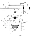
- Fig.1 shows a schematic view of an apparatus with a vacuum chamber 1, on both sides provided with vacuum locks 2,3, through which a strip 4 is guided.
- An evaporator device 5 is positioned inside the vacuum chamber 1 and connected to a vapour distributor 6.
- the means to supply sufficient energy to the evaporator device, such as in induction coil, are also placed inside the vacuum chamber. For the sake of clarity these means are not shown in the drawing.
- the vacuum chamber is further provided with vacuum pump 7 and manometer 8.
- a closed container 9 is provided with inside the container a vessel 10 to hold a liquid metal.
- the closed container 9 is further provided with a pump 11, manometer 12 and overpressure relay 13.
- the vessel is provided with heating means (not shown) to heat and melt the metal and/or to keep the liquid metal at a certain temperature.
- a gas supply 31 with a valve 32 is connected to closed container 9 to replace the air initially present in container 9 with a non-oxidising gas, for instance N2.
- Lifting means 14 are provided to lift and lower vessel 10 to be able to immerse the end of feed tube 15 into the liquid metal or lift it out of the liquid metal.
- the lifting means 14 can also be used in the control of the flow rate of the liquid metal to the evaporator device 5, since with the lifting and lowering the distance between the liquid level in the vessel and that in the evaporation device changes.
- the vessel 10 is placed on weighing devices 35 which allows to continuously weigh the content of vessel 10 which provides additional information on the flow rate of the liquid metal and the evaporation rate.
- the pump 11 is used to lower the pressure in the closed container.
- the air in the closed container can be removed and replaced completely or partially with an inert gas. With this operation the air is first partially removed therewith lowering the pressure before being replaced by an inert gas after which the pressure in the closed container is adjusted and controlled in order to control the flow rate of the liquid metal to the evaporator device.
- the feed tube 15 runs from the vessel 10 inside the closed container 9 in upward direction to the evaporator device 5 and in the feed tube an electromagnetic pump 16 and a valve 17 are provided.
- the electromagnetic pump 16 and valve 17 are placed inside a vacuum enclosure 18.
- the vacuum enclosure 18 is kept at a low vacuum during operation which prevent heat losses through convection from the electromagnetic pump 16 as well as from the feed tube 15 to a great degree.
- the vacuum enclosure 18 is provided with a vacuum pump 34 and a manometer 35.
- the vacuum enclosure 18 connects to the closed container 9 and the vacuum chamber 1 by means of bellows 19, 20.
- the connection by means of the bellows 19, 20 is to the outside of the closed container 9 and the vacuum chamber 1 and does not connect the internal spaces of container 9 and vacuum chamber 1.
- the unavoidable vacuum leak at the feed through of the feed tube 15 into the vacuum chamber 1 is much less because of the low vacuum in the vacuum enclosure 18.
- the electromagnetic pump 16 pump is provided with a permanent magnet 21 to generate a magnetic field and a power supply to pass a current through the liquid metal in the electromagnetic pump.
- the Lorentz force resulting from the magnetic field and the current will exert a force on the liquid metal which is used in the control of the flow rate of the liquid metal.
- the Lorentz force only works as long as the liquid metal is in contact with the electrodes 22 of the electromagnetic pump and within the magnetic field of permanent magnet 21. As a result when the liquid metal is forced downwards the liquid metal level can not be lower than a level at about the height of the electrodes.
- the magnet 21 is not overheated because this will result in a decrease of the strength of the magnetic field. For that reason the magnet 21 is placed outside the vacuum enclosure 18, which at least at the location of the magnet and its magnetic field is made of a non-ferromagnetic material.
- Fig.2A shows a schematic view of an electromagnetic pump 16 for a feed tube 15 with the electrodes 22 on opposite sides against the body of the electromagnetic pump 16.
- the electrodes 22 are connected to a power supply 23, in this case a variable DC power supply.
- Perpendicular to the electrodes 22 are the poles of magnet 21, which in this configuration are two permanent magnets connected by means of a yoke (not shown).
- a yoke not shown
- an electromagnet for instance an electromagnet with a DC coil. By varying the current through the coil the magnetic field could be varied.
- variable DC power supply and a DC coil instead of a variable DC power supply and a DC coil it is as well possible to use a variable AC power supply and an AC coil for the electromagnet.
- Fig.2B shows a configuration with a feed tube 15 and a return tube 24 next to each other with electromagnetic pumps 18, 25 for respectively the feed tube 15 and return tube 24.
- the magnetic field for both the feed tube 15 and the return tube 24 is provided with the same permanent magnets 21.
- Separate variable DC power supplies 23, 26 are provided for respectively the feed tube 15 and the return tube 24 which are reversely connected to the electrodes since the Lorentz forces should be in opposite direction.
- the feed tube 15 and the return tube 24 are in thermal contact with each other but electrically isolated from each other.
- the flow rate in the return tube will differ by the evaporation rate from the flow rate in the feed tube and for that reason the current through the return tube 24 will be larger than through the feed tube 15.
- Fig.2C shows a configuration wherein the electrodes 22 of feed tube 15 and feed tube 24 are connected in series which only requires one power supply 23 and wherein the same current passes through both feed tubes.
- the magnetic field of the magnet 21, 36 in each tube 15, 24 is controlled separately.
- Fig. 3A,3B shows schematically two configurations to control the strength of the magnetic field of permant magnets by shorting the flux or by changing the distance of the magnetic poles to the electromagnetic pump.
- the flux between the poles of magnet 21 can be changed by shortening the magnetic flux via a second leg 38.
- the flux is variable by changing the distance between the poles of this second leg.
- To this end leg 38 of the yoke is designed to allow such linear displacement.
- FIG.3B the magnetic strength is varied by varying the distance between the poles of magnet 21. This can be varied by a rotation or linear displacement.
- a rotational displacement is depicted in Fig. 3B where yoke 37 is provided with a pivoting point 39 and a spindle device 40 for a controlled rotation and therewith a controlled change of the distance between the poles of the magnet 21.
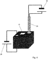
- Fig.4 shows schematically a segment of a feed tube 15 with a channel 27 and two different heating embodiments.
- a first heating method is heating the feed tube by resistance heating with a power source 28 wherein the material of the feed tube serves as the resistance.
- the second heating method is with a sheath heater 29 with a power source 30, wherein the heater is provided in a hole or a recess in the feed tube 15.
- the power sources 28, 30 could be DC or AC power sources. This is in fact also resistance heating wherein the resistance is enclosed in a sheath and electrically isolated from the feed tube. All the tubing must be heated to a temperature above the melting point of the liquid metal for which a temperature of 40 °C above the melting temperature will in general be sufficient.
Landscapes
- Engineering & Computer Science (AREA)
- Chemical & Material Sciences (AREA)
- Mechanical Engineering (AREA)
- Power Engineering (AREA)
- Chemical Kinetics & Catalysis (AREA)
- Materials Engineering (AREA)
- Metallurgy (AREA)
- Organic Chemistry (AREA)
- General Engineering & Computer Science (AREA)
- Vaporization, Distillation, Condensation, Sublimation, And Cold Traps (AREA)
- Compressors, Vaccum Pumps And Other Relevant Systems (AREA)
- Physical Vapour Deposition (AREA)
Claims (15)
- Procédé pour réguler la température d'une pompe électromagnétique dans un appareil, un métal liquide étant fourni, à travers un tube d'alimentation à partir d'un récipient adapté pour contenir un métal liquide, à un dispositif d'évaporateur dans une chambre à vide, la fourniture du métal liquide étant régulée par l'exercice d'une force sur le métal liquide dans le récipient, par la pression dans le dispositif d'évaporateur et par la pompe électromagnétique dans le tube d'alimentation, caractérisée en ce que le procédé comprend :- la fourniture d'une pompe électromagnétique qui est au moins partiellement constituée d'un matériau conducteur électrique,- la fourniture du courant pour la pompe électromagnétique à travers le matériau conducteur électrique, et
la régulation de la température de la pompe électromagnétique en régulant l'un ou plusieurs de- la force exercée sur le métal liquide dans le récipient,- le courant de la pompe électromagnétique, et/ou- l'intensité du champ magnétique de la pompe électromagnétique. - Procédé selon la revendication 1, ladite force exercée sur le métal liquide dans le récipient, ledit courant pour la pompe électromagnétique et/ou ladite force du champ magnétique de la pompe électromagnétique étant régulés en fonction de la fourniture nécessaire de métal liquide au dispositif d'évaporateur.
- Procédé selon la revendication 1 ou 2, ledit récipient adapté pour contenir un métal liquide étant un récipient fermé et ladite force exercée sur le métal liquide dans le récipient étant régulée en régulant la pression d'un gaz dans le récipient fermé.
- Procédé selon l'une quelconque des revendications précédentes, ladite pompe électromagnétique étant prévue d'être au moins partiellement constituée de graphite.
- Procédé selon l'une quelconque des revendications précédentes, des électrodes pour fournir le courant pour la pompe électromagnétique étant disposées contre la pompe.
- Procédé selon l'une quelconque des revendications précédentes, ladite pompe électromagnétique étant disposée dans une enceinte à vide.
- Procédé selon la revendication 6, ladite enceinte à vide renfermant en outre au moins une partie du tube d'alimentation.
- Procédé selon l'une quelconque des revendications précédentes, ledit tube d'alimentation étant chauffé.
- Procédé selon la revendication 7, ledit tube d'alimentation étant chauffé au moyen de chauffage par résistance ou au moyen de chauffages dans la paroi du tube d'alimentation.
- Procédé selon l'une quelconque des revendications précédentes, un tube de retour et une pompe électromagnétique dans le tube de retour étant prévus, ledit tube de retour s'étendant à partir du dispositif d'évaporateur jusqu'au récipient fermé, ladite pompe électromagnétique dans le tube de retour étant au moins partiellement constituée d'un matériau conducteur électrique et ledit courant pour la pompe électromagnétique étant fourni à travers le matériau conducteur électrique et ladite température de la pompe électromagnétique dans le tube de retour étant régulée en régulant le courant de la pompe électromagnétique et/ou l'intensité du champ magnétique de la pompe électromagnétique.
- Procédé selon la revendication 10, ladite pompe électromagnétique dans le tube de retour étant positionnée parallèlement à la pompe électromagnétique dans le tube d'alimentation.
- Procédé selon la revendication 11, ladite pompe électromagnétique dans le tube de retour et ladite pompe électromagnétique dans le tube d'alimentation possédant un aimant commun.
- Procédé selon la revendication 10, ladite pompe électromagnétique dans le tube de retour étant positionnée en série avec la pompe électromagnétique dans le tube d'alimentation
et des électrodes en regard des pompes électromagnétiques étant raccordées. - Procédé selon la revendication 13, ladite pompe électromagnétique dans le tube de retour et ladite pompe électromagnétique dans le tube d'alimentation possédant chacune leur propre aimant.
- Procédé selon l'une quelconque des revendications précédentes, ledit champ magnétique de la pompe électromagnétique étant régulé en régulant la distance des pôles magnétiques par rapport à la pompe électromagnétique et/ou en régulant le champ magnétique fourni par un électroaimant en régulant un courant continu ou alternatif à travers la bobine de l'électro-aimant.
Applications Claiming Priority (2)
| Application Number | Priority Date | Filing Date | Title |
|---|---|---|---|
| EP16168173 | 2016-05-03 | ||
| PCT/EP2017/060315 WO2017191081A1 (fr) | 2016-05-03 | 2017-05-01 | Procédé de régulation de température de pompe électromagnétique |
Publications (2)
| Publication Number | Publication Date |
|---|---|
| EP3452632A1 EP3452632A1 (fr) | 2019-03-13 |
| EP3452632B1 true EP3452632B1 (fr) | 2020-07-08 |
Family
ID=56108463
Family Applications (1)
| Application Number | Title | Priority Date | Filing Date |
|---|---|---|---|
| EP17720141.5A Not-in-force EP3452632B1 (fr) | 2016-05-03 | 2017-05-01 | Procédé de régulation de température de pompe électromagnétique |
Country Status (8)
| Country | Link |
|---|---|
| US (1) | US11261860B2 (fr) |
| EP (1) | EP3452632B1 (fr) |
| JP (1) | JP7166174B2 (fr) |
| KR (1) | KR102392869B1 (fr) |
| CN (1) | CN109154070B (fr) |
| AU (1) | AU2017260146A1 (fr) |
| ES (1) | ES2807962T3 (fr) |
| WO (1) | WO2017191081A1 (fr) |
Families Citing this family (6)
| Publication number | Priority date | Publication date | Assignee | Title |
|---|---|---|---|---|
| AU2017260148B2 (en) | 2016-05-03 | 2022-08-25 | Tata Steel Nederland Technology B.V. | Method to operate an apparatus for feeding liquid metal to an evaporator device |
| WO2017191082A1 (fr) | 2016-05-03 | 2017-11-09 | Tata Steel Nederland Technology B.V. | Appareil destiné à alimenter en matériau liquide un dispositif d'évaporation |
| EP3736444A1 (fr) | 2019-05-09 | 2020-11-11 | Excillum AB | Pompe électromagnétique |
| FR3100945B1 (fr) * | 2019-09-12 | 2021-09-24 | Commissariat Energie Atomique | Pompe électromagnétique annulaire à induction |
| CN112803712B (zh) * | 2021-01-29 | 2022-07-01 | 中国原子能科学研究院 | 液态金属电磁泵 |
| CN115276367B (zh) * | 2022-08-12 | 2025-07-29 | 江苏大学 | 一种输送超高温液态金属的圆柱式线性感应电磁泵 |
Family Cites Families (37)
| Publication number | Priority date | Publication date | Assignee | Title |
|---|---|---|---|---|
| US2664852A (en) | 1950-04-27 | 1954-01-05 | Nat Res Corp | Vapor coating apparatus |
| US3059612A (en) | 1959-10-19 | 1962-10-23 | Wean Engineering Co Inc | Vacuum coating apparatus |
| US3408224A (en) | 1964-06-25 | 1968-10-29 | Pennsalt Chemicals Corp | Vapor coating employing degassing of coating metal |
| US3581766A (en) | 1968-08-02 | 1971-06-01 | Jones & Laughlin Steel Corp | Supplying liquid to a vacuum chamber |
| US3550924A (en) | 1968-12-06 | 1970-12-29 | United States Steel Corp | Mechanism for controlling flow of liquid to a vacuum-treating vessel |
| US4392786A (en) | 1980-10-16 | 1983-07-12 | Merenkov Jury F | Electromagnetic induction pump |
| JPS5938379A (ja) * | 1982-08-26 | 1984-03-02 | Mitsubishi Heavy Ind Ltd | 真空蒸着装置のスタ−トアツプ法 |
| JPS59177369A (ja) * | 1983-03-29 | 1984-10-08 | Mitsubishi Heavy Ind Ltd | 真空蒸着装置 |
| SU1698939A1 (ru) * | 1987-12-17 | 1991-12-15 | Всесоюзный научно-исследовательский, проектно-конструкторский и технологический институт электросварочного оборудования | Устройство дл дозированной подачи сплавов |
| JPH064442B2 (ja) * | 1988-01-14 | 1994-01-19 | 株式会社フジタ | 廃棄物輪送装置 |
| JPH058795Y2 (fr) * | 1988-02-05 | 1993-03-04 | ||
| JPH0299254A (ja) * | 1988-05-16 | 1990-04-11 | Nippon Steel Corp | 薄肉鋼板連続鋳造機の湯面制御装置及び湯面制御方法 |
| US5209646A (en) * | 1991-10-16 | 1993-05-11 | The University Of Chicago | Electromagnetic induction pump for pumping liquid metals and other conductive liquids |
| US5388633A (en) | 1992-02-13 | 1995-02-14 | The Dow Chemical Company | Method and apparatus for charging metal to a die cast |
| FR2698742B1 (fr) * | 1992-11-30 | 1995-02-17 | Framatome Sa | Machine électromagnétique à induction linéaire à répartition de flux magnétique optimisée et utilisations. |
| CN2486822Y (zh) * | 2001-07-31 | 2002-04-17 | 杨家华 | 热力管网绝热保温结构 |
| JP4211528B2 (ja) * | 2003-08-01 | 2009-01-21 | パナソニック株式会社 | 導電性流体の供給装置及び供給方法 |
| US7339139B2 (en) | 2003-10-03 | 2008-03-04 | Darly Custom Technology, Inc. | Multi-layered radiant thermal evaporator and method of use |
| JP2005205479A (ja) | 2004-01-26 | 2005-08-04 | Toshiba Corp | はんだ付け装置 |
| DE102006041863B4 (de) * | 2006-09-06 | 2012-08-23 | Continental Automotive Gmbh | Verfahren und Vorrichtung zum Erwärmen eines Elektrolyten und Verwendung einer magnetohydrodynamischen Pumpe |
| CN101018005B (zh) * | 2007-02-15 | 2011-06-29 | 沈阳铝镁设计研究院有限公司 | 直流电磁泵 |
| EP1972699A1 (fr) * | 2007-03-20 | 2008-09-24 | ArcelorMittal France | Procede de revetement d'un substrat et installation de depot sous vide d'alliage metallique |
| JP2009114894A (ja) * | 2007-11-02 | 2009-05-28 | Toshiba Corp | リニア電磁ポンプと熱交換装置 |
| IT1393394B1 (it) * | 2009-03-23 | 2012-04-20 | Schiavolin | Dispositivo di deumidificazione per materie plastiche |
| CN101582627A (zh) | 2009-06-29 | 2009-11-18 | 中国科学院等离子体物理研究所 | 液态金属电磁泵 |
| US20110195187A1 (en) * | 2010-02-10 | 2011-08-11 | Apple Inc. | Direct liquid vaporization for oleophobic coatings |
| CN101961628B (zh) * | 2010-11-04 | 2013-03-27 | 迈瑞尔实验设备(上海)有限公司 | 一种中小型绝热反应器 |
| WO2012081738A1 (fr) | 2010-12-13 | 2012-06-21 | Posco | Appareil de revêtement continu |
| ES2566607T3 (es) | 2012-03-30 | 2016-04-14 | Tata Steel Nederland Technology B.V. | Método y aparato para cargar metal líquido en un dispositivo evaporador |
| CN103166420B (zh) * | 2013-02-01 | 2015-10-07 | 中国科学院合肥物质科学研究院 | 一种液态金属磁力驱动装置 |
| US20150219122A1 (en) * | 2013-02-02 | 2015-08-06 | Jan Vetrovec | Direct current magnetohydrodynamic pump |
| CN103090156B (zh) * | 2013-02-26 | 2015-09-30 | 沈双喜 | 真空隔热保温热流体节能输送管道 |
| US10131983B2 (en) | 2013-11-05 | 2018-11-20 | Tata Steel Nederland Technology B.V. | Method and apparatus for controlling the composition of liquid metal in an evaporator device |
| CN204805055U (zh) | 2015-04-29 | 2015-11-25 | 周小林 | 电磁泵 |
| CN205017197U (zh) * | 2015-10-16 | 2016-02-03 | 北京依米康科技发展有限公司 | 一种新型液态金属电磁泵 |
| AU2017260148B2 (en) | 2016-05-03 | 2022-08-25 | Tata Steel Nederland Technology B.V. | Method to operate an apparatus for feeding liquid metal to an evaporator device |
| WO2017191082A1 (fr) | 2016-05-03 | 2017-11-09 | Tata Steel Nederland Technology B.V. | Appareil destiné à alimenter en matériau liquide un dispositif d'évaporation |
-
2017
- 2017-05-01 JP JP2018557819A patent/JP7166174B2/ja active Active
- 2017-05-01 CN CN201780027324.6A patent/CN109154070B/zh not_active Expired - Fee Related
- 2017-05-01 WO PCT/EP2017/060315 patent/WO2017191081A1/fr not_active Ceased
- 2017-05-01 ES ES17720141T patent/ES2807962T3/es active Active
- 2017-05-01 EP EP17720141.5A patent/EP3452632B1/fr not_active Not-in-force
- 2017-05-01 US US16/098,493 patent/US11261860B2/en not_active Expired - Fee Related
- 2017-05-01 AU AU2017260146A patent/AU2017260146A1/en not_active Abandoned
- 2017-05-01 KR KR1020187033591A patent/KR102392869B1/ko not_active Expired - Fee Related
Non-Patent Citations (1)
| Title |
|---|
| D.A. WATT: "The design of electromagnetic pumps for liquid metals", PROCEEDINGS OF THE IEE - PART A: POWER ENGINEERING, vol. 106, no. 26, 1 January 1959 (1959-01-01), UK, pages 94, XP055613120, ISSN: 0369-8882, DOI: 10.1049/pi-a.1959.0054 * |
Also Published As
| Publication number | Publication date |
|---|---|
| WO2017191081A1 (fr) | 2017-11-09 |
| JP2019515623A (ja) | 2019-06-06 |
| AU2017260146A1 (en) | 2018-11-15 |
| ES2807962T3 (es) | 2021-02-24 |
| EP3452632A1 (fr) | 2019-03-13 |
| CN109154070B (zh) | 2022-03-29 |
| JP7166174B2 (ja) | 2022-11-07 |
| US20210239110A1 (en) | 2021-08-05 |
| KR102392869B1 (ko) | 2022-04-29 |
| KR20190003588A (ko) | 2019-01-09 |
| CN109154070A (zh) | 2019-01-04 |
| US11261860B2 (en) | 2022-03-01 |
Similar Documents
| Publication | Publication Date | Title |
|---|---|---|
| EP3452632B1 (fr) | Procédé de régulation de température de pompe électromagnétique | |
| EP3452631B1 (fr) | Procédé d'exploitation d'un appareil destiné à alimenter un dispositif évaporateur en métal liquide | |
| EP3452633B1 (fr) | Appareil pour l'introduction de métal liquide dans un dispositif évaporateur | |
| KR102087460B1 (ko) | 용융금속을 증발기 장치로 공급하는 방법 및 장치 | |
| JP7315218B2 (ja) | 金属溶湯駆動装置および金属溶湯駆動方法 |
Legal Events
| Date | Code | Title | Description |
|---|---|---|---|
| STAA | Information on the status of an ep patent application or granted ep patent |
Free format text: STATUS: UNKNOWN |
|
| STAA | Information on the status of an ep patent application or granted ep patent |
Free format text: STATUS: THE INTERNATIONAL PUBLICATION HAS BEEN MADE |
|
| PUAI | Public reference made under article 153(3) epc to a published international application that has entered the european phase |
Free format text: ORIGINAL CODE: 0009012 |
|
| STAA | Information on the status of an ep patent application or granted ep patent |
Free format text: STATUS: REQUEST FOR EXAMINATION WAS MADE |
|
| 17P | Request for examination filed |
Effective date: 20181203 |
|
| AK | Designated contracting states |
Kind code of ref document: A1 Designated state(s): AL AT BE BG CH CY CZ DE DK EE ES FI FR GB GR HR HU IE IS IT LI LT LU LV MC MK MT NL NO PL PT RO RS SE SI SK SM TR |
|
| AX | Request for extension of the european patent |
Extension state: BA ME |
|
| DAV | Request for validation of the european patent (deleted) | ||
| DAX | Request for extension of the european patent (deleted) | ||
| STAA | Information on the status of an ep patent application or granted ep patent |
Free format text: STATUS: EXAMINATION IS IN PROGRESS |
|
| 17Q | First examination report despatched |
Effective date: 20190821 |
|
| GRAP | Despatch of communication of intention to grant a patent |
Free format text: ORIGINAL CODE: EPIDOSNIGR1 |
|
| STAA | Information on the status of an ep patent application or granted ep patent |
Free format text: STATUS: GRANT OF PATENT IS INTENDED |
|
| RIC1 | Information provided on ipc code assigned before grant |
Ipc: H02P 29/60 20160101ALI20200108BHEP Ipc: H02K 44/02 20060101ALI20200108BHEP Ipc: C23C 14/24 20060101AFI20200108BHEP |
|
| INTG | Intention to grant announced |
Effective date: 20200207 |
|
| GRAS | Grant fee paid |
Free format text: ORIGINAL CODE: EPIDOSNIGR3 |
|
| GRAA | (expected) grant |
Free format text: ORIGINAL CODE: 0009210 |
|
| STAA | Information on the status of an ep patent application or granted ep patent |
Free format text: STATUS: THE PATENT HAS BEEN GRANTED |
|
| AK | Designated contracting states |
Kind code of ref document: B1 Designated state(s): AL AT BE BG CH CY CZ DE DK EE ES FI FR GB GR HR HU IE IS IT LI LT LU LV MC MK MT NL NO PL PT RO RS SE SI SK SM TR |
|
| REG | Reference to a national code |
Ref country code: CH Ref legal event code: EP Ref country code: AT Ref legal event code: REF Ref document number: 1288522 Country of ref document: AT Kind code of ref document: T Effective date: 20200715 |
|
| REG | Reference to a national code |
Ref country code: DE Ref legal event code: R096 Ref document number: 602017019376 Country of ref document: DE |
|
| REG | Reference to a national code |
Ref country code: IE Ref legal event code: FG4D |
|
| REG | Reference to a national code |
Ref country code: SE Ref legal event code: TRGR |
|
| REG | Reference to a national code |
Ref country code: LT Ref legal event code: MG4D |
|
| REG | Reference to a national code |
Ref country code: AT Ref legal event code: MK05 Ref document number: 1288522 Country of ref document: AT Kind code of ref document: T Effective date: 20200708 |
|
| REG | Reference to a national code |
Ref country code: NL Ref legal event code: MP Effective date: 20200708 |
|
| PG25 | Lapsed in a contracting state [announced via postgrant information from national office to epo] |
Ref country code: LT Free format text: LAPSE BECAUSE OF FAILURE TO SUBMIT A TRANSLATION OF THE DESCRIPTION OR TO PAY THE FEE WITHIN THE PRESCRIBED TIME-LIMIT Effective date: 20200708 Ref country code: FI Free format text: LAPSE BECAUSE OF FAILURE TO SUBMIT A TRANSLATION OF THE DESCRIPTION OR TO PAY THE FEE WITHIN THE PRESCRIBED TIME-LIMIT Effective date: 20200708 Ref country code: PT Free format text: LAPSE BECAUSE OF FAILURE TO SUBMIT A TRANSLATION OF THE DESCRIPTION OR TO PAY THE FEE WITHIN THE PRESCRIBED TIME-LIMIT Effective date: 20201109 Ref country code: BG Free format text: LAPSE BECAUSE OF FAILURE TO SUBMIT A TRANSLATION OF THE DESCRIPTION OR TO PAY THE FEE WITHIN THE PRESCRIBED TIME-LIMIT Effective date: 20201008 Ref country code: HR Free format text: LAPSE BECAUSE OF FAILURE TO SUBMIT A TRANSLATION OF THE DESCRIPTION OR TO PAY THE FEE WITHIN THE PRESCRIBED TIME-LIMIT Effective date: 20200708 Ref country code: AT Free format text: LAPSE BECAUSE OF FAILURE TO SUBMIT A TRANSLATION OF THE DESCRIPTION OR TO PAY THE FEE WITHIN THE PRESCRIBED TIME-LIMIT Effective date: 20200708 Ref country code: GR Free format text: LAPSE BECAUSE OF FAILURE TO SUBMIT A TRANSLATION OF THE DESCRIPTION OR TO PAY THE FEE WITHIN THE PRESCRIBED TIME-LIMIT Effective date: 20201009 Ref country code: NO Free format text: LAPSE BECAUSE OF FAILURE TO SUBMIT A TRANSLATION OF THE DESCRIPTION OR TO PAY THE FEE WITHIN THE PRESCRIBED TIME-LIMIT Effective date: 20201008 |
|
| REG | Reference to a national code |
Ref country code: ES Ref legal event code: FG2A Ref document number: 2807962 Country of ref document: ES Kind code of ref document: T3 Effective date: 20210224 |
|
| PG25 | Lapsed in a contracting state [announced via postgrant information from national office to epo] |
Ref country code: PL Free format text: LAPSE BECAUSE OF FAILURE TO SUBMIT A TRANSLATION OF THE DESCRIPTION OR TO PAY THE FEE WITHIN THE PRESCRIBED TIME-LIMIT Effective date: 20200708 Ref country code: RS Free format text: LAPSE BECAUSE OF FAILURE TO SUBMIT A TRANSLATION OF THE DESCRIPTION OR TO PAY THE FEE WITHIN THE PRESCRIBED TIME-LIMIT Effective date: 20200708 Ref country code: LV Free format text: LAPSE BECAUSE OF FAILURE TO SUBMIT A TRANSLATION OF THE DESCRIPTION OR TO PAY THE FEE WITHIN THE PRESCRIBED TIME-LIMIT Effective date: 20200708 Ref country code: IS Free format text: LAPSE BECAUSE OF FAILURE TO SUBMIT A TRANSLATION OF THE DESCRIPTION OR TO PAY THE FEE WITHIN THE PRESCRIBED TIME-LIMIT Effective date: 20201108 |
|
| PG25 | Lapsed in a contracting state [announced via postgrant information from national office to epo] |
Ref country code: NL Free format text: LAPSE BECAUSE OF FAILURE TO SUBMIT A TRANSLATION OF THE DESCRIPTION OR TO PAY THE FEE WITHIN THE PRESCRIBED TIME-LIMIT Effective date: 20200708 |
|
| REG | Reference to a national code |
Ref country code: DE Ref legal event code: R097 Ref document number: 602017019376 Country of ref document: DE |
|
| PG25 | Lapsed in a contracting state [announced via postgrant information from national office to epo] |
Ref country code: EE Free format text: LAPSE BECAUSE OF FAILURE TO SUBMIT A TRANSLATION OF THE DESCRIPTION OR TO PAY THE FEE WITHIN THE PRESCRIBED TIME-LIMIT Effective date: 20200708 Ref country code: SM Free format text: LAPSE BECAUSE OF FAILURE TO SUBMIT A TRANSLATION OF THE DESCRIPTION OR TO PAY THE FEE WITHIN THE PRESCRIBED TIME-LIMIT Effective date: 20200708 Ref country code: RO Free format text: LAPSE BECAUSE OF FAILURE TO SUBMIT A TRANSLATION OF THE DESCRIPTION OR TO PAY THE FEE WITHIN THE PRESCRIBED TIME-LIMIT Effective date: 20200708 Ref country code: DK Free format text: LAPSE BECAUSE OF FAILURE TO SUBMIT A TRANSLATION OF THE DESCRIPTION OR TO PAY THE FEE WITHIN THE PRESCRIBED TIME-LIMIT Effective date: 20200708 |
|
| PLBE | No opposition filed within time limit |
Free format text: ORIGINAL CODE: 0009261 |
|
| STAA | Information on the status of an ep patent application or granted ep patent |
Free format text: STATUS: NO OPPOSITION FILED WITHIN TIME LIMIT |
|
| PG25 | Lapsed in a contracting state [announced via postgrant information from national office to epo] |
Ref country code: AL Free format text: LAPSE BECAUSE OF FAILURE TO SUBMIT A TRANSLATION OF THE DESCRIPTION OR TO PAY THE FEE WITHIN THE PRESCRIBED TIME-LIMIT Effective date: 20200708 |
|
| 26N | No opposition filed |
Effective date: 20210409 |
|
| PG25 | Lapsed in a contracting state [announced via postgrant information from national office to epo] |
Ref country code: SK Free format text: LAPSE BECAUSE OF FAILURE TO SUBMIT A TRANSLATION OF THE DESCRIPTION OR TO PAY THE FEE WITHIN THE PRESCRIBED TIME-LIMIT Effective date: 20200708 |
|
| PGFP | Annual fee paid to national office [announced via postgrant information from national office to epo] |
Ref country code: CZ Payment date: 20210421 Year of fee payment: 5 Ref country code: IT Payment date: 20210524 Year of fee payment: 5 |
|
| PG25 | Lapsed in a contracting state [announced via postgrant information from national office to epo] |
Ref country code: SI Free format text: LAPSE BECAUSE OF FAILURE TO SUBMIT A TRANSLATION OF THE DESCRIPTION OR TO PAY THE FEE WITHIN THE PRESCRIBED TIME-LIMIT Effective date: 20200708 |
|
| PGFP | Annual fee paid to national office [announced via postgrant information from national office to epo] |
Ref country code: GB Payment date: 20210527 Year of fee payment: 5 Ref country code: ES Payment date: 20210601 Year of fee payment: 5 Ref country code: SE Payment date: 20210527 Year of fee payment: 5 |
|
| REG | Reference to a national code |
Ref country code: CH Ref legal event code: PL |
|
| PG25 | Lapsed in a contracting state [announced via postgrant information from national office to epo] |
Ref country code: LU Free format text: LAPSE BECAUSE OF NON-PAYMENT OF DUE FEES Effective date: 20210501 Ref country code: MC Free format text: LAPSE BECAUSE OF FAILURE TO SUBMIT A TRANSLATION OF THE DESCRIPTION OR TO PAY THE FEE WITHIN THE PRESCRIBED TIME-LIMIT Effective date: 20200708 Ref country code: LI Free format text: LAPSE BECAUSE OF NON-PAYMENT OF DUE FEES Effective date: 20210531 Ref country code: CH Free format text: LAPSE BECAUSE OF NON-PAYMENT OF DUE FEES Effective date: 20210531 |
|
| PG25 | Lapsed in a contracting state [announced via postgrant information from national office to epo] |
Ref country code: IE Free format text: LAPSE BECAUSE OF NON-PAYMENT OF DUE FEES Effective date: 20210501 |
|
| REG | Reference to a national code |
Ref country code: SE Ref legal event code: EUG |
|
| GBPC | Gb: european patent ceased through non-payment of renewal fee |
Effective date: 20220501 |
|
| PG25 | Lapsed in a contracting state [announced via postgrant information from national office to epo] |
Ref country code: SE Free format text: LAPSE BECAUSE OF NON-PAYMENT OF DUE FEES Effective date: 20220502 Ref country code: CZ Free format text: LAPSE BECAUSE OF NON-PAYMENT OF DUE FEES Effective date: 20220501 |
|
| PG25 | Lapsed in a contracting state [announced via postgrant information from national office to epo] |
Ref country code: GB Free format text: LAPSE BECAUSE OF NON-PAYMENT OF DUE FEES Effective date: 20220501 |
|
| P01 | Opt-out of the competence of the unified patent court (upc) registered |
Effective date: 20230517 |
|
| REG | Reference to a national code |
Ref country code: ES Ref legal event code: FD2A Effective date: 20230626 |
|
| PG25 | Lapsed in a contracting state [announced via postgrant information from national office to epo] |
Ref country code: CY Free format text: LAPSE BECAUSE OF FAILURE TO SUBMIT A TRANSLATION OF THE DESCRIPTION OR TO PAY THE FEE WITHIN THE PRESCRIBED TIME-LIMIT Effective date: 20200708 |
|
| PG25 | Lapsed in a contracting state [announced via postgrant information from national office to epo] |
Ref country code: IT Free format text: LAPSE BECAUSE OF NON-PAYMENT OF DUE FEES Effective date: 20220501 Ref country code: HU Free format text: LAPSE BECAUSE OF FAILURE TO SUBMIT A TRANSLATION OF THE DESCRIPTION OR TO PAY THE FEE WITHIN THE PRESCRIBED TIME-LIMIT; INVALID AB INITIO Effective date: 20170501 Ref country code: ES Free format text: LAPSE BECAUSE OF NON-PAYMENT OF DUE FEES Effective date: 20220502 |
|
| PG25 | Lapsed in a contracting state [announced via postgrant information from national office to epo] |
Ref country code: MK Free format text: LAPSE BECAUSE OF FAILURE TO SUBMIT A TRANSLATION OF THE DESCRIPTION OR TO PAY THE FEE WITHIN THE PRESCRIBED TIME-LIMIT Effective date: 20200708 |
|
| PG25 | Lapsed in a contracting state [announced via postgrant information from national office to epo] |
Ref country code: TR Free format text: LAPSE BECAUSE OF FAILURE TO SUBMIT A TRANSLATION OF THE DESCRIPTION OR TO PAY THE FEE WITHIN THE PRESCRIBED TIME-LIMIT Effective date: 20200708 |
|
| PGFP | Annual fee paid to national office [announced via postgrant information from national office to epo] |
Ref country code: DE Payment date: 20240530 Year of fee payment: 8 |
|
| PGFP | Annual fee paid to national office [announced via postgrant information from national office to epo] |
Ref country code: FR Payment date: 20240527 Year of fee payment: 8 |
|
| PGFP | Annual fee paid to national office [announced via postgrant information from national office to epo] |
Ref country code: BE Payment date: 20240527 Year of fee payment: 8 |
|
| PG25 | Lapsed in a contracting state [announced via postgrant information from national office to epo] |
Ref country code: MT Free format text: LAPSE BECAUSE OF FAILURE TO SUBMIT A TRANSLATION OF THE DESCRIPTION OR TO PAY THE FEE WITHIN THE PRESCRIBED TIME-LIMIT Effective date: 20200708 |
|
| REG | Reference to a national code |
Ref country code: DE Ref legal event code: R119 Ref document number: 602017019376 Country of ref document: DE |
|
| REG | Reference to a national code |
Ref country code: BE Ref legal event code: MM Effective date: 20250531 |
|
| PG25 | Lapsed in a contracting state [announced via postgrant information from national office to epo] |
Ref country code: DE Free format text: LAPSE BECAUSE OF NON-PAYMENT OF DUE FEES Effective date: 20251202 |
|
| PG25 | Lapsed in a contracting state [announced via postgrant information from national office to epo] |
Ref country code: BE Free format text: LAPSE BECAUSE OF NON-PAYMENT OF DUE FEES Effective date: 20250531 |
|
| PG25 | Lapsed in a contracting state [announced via postgrant information from national office to epo] |
Ref country code: FR Free format text: LAPSE BECAUSE OF NON-PAYMENT OF DUE FEES Effective date: 20250531 |