EP3452707B1 - Dispositif de charge électrique à refroidissement par fluide - Google Patents
Dispositif de charge électrique à refroidissement par fluide Download PDFInfo
- Publication number
- EP3452707B1 EP3452707B1 EP17721947.4A EP17721947A EP3452707B1 EP 3452707 B1 EP3452707 B1 EP 3452707B1 EP 17721947 A EP17721947 A EP 17721947A EP 3452707 B1 EP3452707 B1 EP 3452707B1
- Authority
- EP
- European Patent Office
- Prior art keywords
- stator
- seal
- charging device
- stator housing
- housing
- Prior art date
- Legal status (The legal status is an assumption and is not a legal conclusion. Google has not performed a legal analysis and makes no representation as to the accuracy of the status listed.)
- Active
Links
Images

Classifications
-
- H—ELECTRICITY
- H02—GENERATION; CONVERSION OR DISTRIBUTION OF ELECTRIC POWER
- H02K—DYNAMO-ELECTRIC MACHINES
- H02K9/00—Arrangements for cooling or ventilating
- H02K9/19—Arrangements for cooling or ventilating for machines with closed casing and closed-circuit cooling using a liquid cooling medium, e.g. oil
- H02K9/197—Arrangements for cooling or ventilating for machines with closed casing and closed-circuit cooling using a liquid cooling medium, e.g. oil in which the rotor or stator space is fluid-tight, e.g. to provide for different cooling media for rotor and stator
-
- F—MECHANICAL ENGINEERING; LIGHTING; HEATING; WEAPONS; BLASTING
- F02—COMBUSTION ENGINES; HOT-GAS OR COMBUSTION-PRODUCT ENGINE PLANTS
- F02B—INTERNAL-COMBUSTION PISTON ENGINES; COMBUSTION ENGINES IN GENERAL
- F02B39/00—Component parts, details, or accessories relating to, driven charging or scavenging pumps, not provided for in groups F02B33/00 - F02B37/00
- F02B39/005—Cooling of pump drives
-
- F—MECHANICAL ENGINEERING; LIGHTING; HEATING; WEAPONS; BLASTING
- F02—COMBUSTION ENGINES; HOT-GAS OR COMBUSTION-PRODUCT ENGINE PLANTS
- F02B—INTERNAL-COMBUSTION PISTON ENGINES; COMBUSTION ENGINES IN GENERAL
- F02B39/00—Component parts, details, or accessories relating to, driven charging or scavenging pumps, not provided for in groups F02B33/00 - F02B37/00
- F02B39/02—Drives of pumps; Varying pump drive gear ratio
- F02B39/08—Non-mechanical drives, e.g. fluid drives having variable gear ratio
- F02B39/10—Non-mechanical drives, e.g. fluid drives having variable gear ratio electric
-
- F—MECHANICAL ENGINEERING; LIGHTING; HEATING; WEAPONS; BLASTING
- F04—POSITIVE - DISPLACEMENT MACHINES FOR LIQUIDS; PUMPS FOR LIQUIDS OR ELASTIC FLUIDS
- F04D—NON-POSITIVE-DISPLACEMENT PUMPS
- F04D17/00—Radial-flow pumps, e.g. centrifugal pumps; Helico-centrifugal pumps
- F04D17/08—Centrifugal pumps
- F04D17/10—Centrifugal pumps for compressing or evacuating
-
- F—MECHANICAL ENGINEERING; LIGHTING; HEATING; WEAPONS; BLASTING
- F04—POSITIVE - DISPLACEMENT MACHINES FOR LIQUIDS; PUMPS FOR LIQUIDS OR ELASTIC FLUIDS
- F04D—NON-POSITIVE-DISPLACEMENT PUMPS
- F04D25/00—Pumping installations or systems
- F04D25/02—Units comprising pumps and their driving means
- F04D25/06—Units comprising pumps and their driving means the pump being electrically driven
-
- F—MECHANICAL ENGINEERING; LIGHTING; HEATING; WEAPONS; BLASTING
- F04—POSITIVE - DISPLACEMENT MACHINES FOR LIQUIDS; PUMPS FOR LIQUIDS OR ELASTIC FLUIDS
- F04D—NON-POSITIVE-DISPLACEMENT PUMPS
- F04D29/00—Details, component parts, or accessories
- F04D29/58—Cooling; Heating; Diminishing heat transfer
- F04D29/5806—Cooling the drive system
-
- H—ELECTRICITY
- H02—GENERATION; CONVERSION OR DISTRIBUTION OF ELECTRIC POWER
- H02K—DYNAMO-ELECTRIC MACHINES
- H02K5/00—Casings; Enclosures; Supports
- H02K5/04—Casings or enclosures characterised by the shape, form or construction thereof
- H02K5/12—Casings or enclosures characterised by the shape, form or construction thereof specially adapted for operating in liquid or gas
- H02K5/128—Casings or enclosures characterised by the shape, form or construction thereof specially adapted for operating in liquid or gas using air-gap sleeves or air-gap discs
-
- H—ELECTRICITY
- H02—GENERATION; CONVERSION OR DISTRIBUTION OF ELECTRIC POWER
- H02K—DYNAMO-ELECTRIC MACHINES
- H02K5/00—Casings; Enclosures; Supports
- H02K5/04—Casings or enclosures characterised by the shape, form or construction thereof
- H02K5/20—Casings or enclosures characterised by the shape, form or construction thereof with channels or ducts for flow of cooling medium
- H02K5/203—Casings or enclosures characterised by the shape, form or construction thereof with channels or ducts for flow of cooling medium specially adapted for liquids, e.g. cooling jackets
Definitions
- the present invention relates to an electric charging device for an internal combustion engine with FLUID cooling.
- exhaust gas turbochargers are known in which a turbine wheel is driven by the exhaust gas flow of the internal combustion engine.
- a compressor wheel which is arranged with a turbine wheel on a mutual shaft, compresses the fresh air taken in for the engine.
- the air or oxygen amount, available to the engine for combustion is increased, which in turn leads to an increased output of the internal combustion engine.
- the disadvantage in exhaust gas turbochargers is that their rotation rate or performance is dependent on the exhaust gas flow, thus on the engine loads. At low engine speeds, in particular, this may negatively affect the effectiveness and efficiency of exhaust gas turbochargers.
- turbochargers also called eBoosters.
- the shaft, on which the compressor wheel is arranged is not driven by the exhaust gas flow from the engine or via a turbine wheel, but instead by an electric motor driving the shaft.
- a rotor is arranged on the shaft with a stator around the rotor. Shaft, rotor, and stator are surrounded by a stator housing. At high loads and during output peaks, these components heat up strongly.
- these types of charging devices have a large design for the stator housing and a low efficiency for cooling the stator.
- EP2053213A1 discloses a motor-driven supercharger with a stator assembly inserted and attached to a bearing housing.
- the stator assembly includes a motor stator and an outer sleeve. Between the outer sleeve and the compressor housing a water cooling jacket is constructed.
- the goal of the present invention is consequently to provide a charging device for an internal combustion engine with a compact design for the stator housing and simultaneously efficient cooling of the stator.
- the present invention relates to a charging device for an internal combustion engine according to Claim 1 and according to Claim 7.
- the charging device according to the invention has the advantage that the stator is directly flushed by cooling fluid and thus an efficient cooling of the stator is facilitated.
- the stator housing can be produced in a die casting method, as no cooling channels need to be provided in the stator housing. This means that a smaller design of the stator housing may be realized, and a reduction of the material costs as well as a simpler and more cost-efficient production of the charging device.
- the charging device according to the invention facilitates a good cooling of the rotor due to the split tube.
- a third seal may be provided in the axial direction between the stator housing and a second end of the split tube so that a dry compartment is created between the first seal and the third seal.
- the dry compartment is used for the dry accommodation of an electrical connection of the stator to a control unit that may be provided, for example, between a housing wall and a housing cover or between a housing wall and a compressor housing back wall.
- a second end of the stator lying opposite the first end of the stator, may be the distal end of the stator, when viewed from the compressor wheel, and the cooling channel may extend radially inward in the direction of the shaft between the stator and the stator housing in the area of the second end of the stator.
- the area of the cooling channel extending radially inward may thereby extend up to a bearing seat of a bearing of the shaft, by which means the bearing seat is cooled.
- the bearing is also indirectly cooled in this way.
- the stator may comprise windings and sealing compound.
- the first seal may be integrated directly into the sealing compound or be formed from the sealing compound.
- Walls of the cooling channel may be formed directly by the stator housing and the sealing compound of the stator. This may be facilitated by the use of a fluid-tight, in particular a water-tight sealing compound.
- a fluid-tight membrane may be provided which surrounds the stator. The walls of the cooling channel are then formed by the membrane and the stator housing.
- the stator housing may comprise a main body and a cover.
- the second seal may, for example, be arranged between the split tube and the cover, in particular a projection of the cover which defines a bearing seat for a bearing for mounting the shaft.
- the invention comprises in a second embodiment a charging device for an internal combustion engine according to claim 7. It is advantageous in this charging device that an efficient cooling of the stator is facilitated, as the coolant is only separated from the stator by a thin separation tube.
- the stator housing may be produced in a die casting method in this embodiment, as no cooling channels need to be provided in the stator housing.
- the separation tube itself may be manufactured in a simple way, for example, by deep drawing. In sum, this means in turn a smaller design of the stator housing and a reduction of the material costs as well as a simpler and more cost-efficient production of the charging device at a simultaneously more efficient stator cooling.
- the first seal may be arranged in the area of the proximal end of the stator, viewed from the compressor wheel, and in the area of the radially outer circumference of the stator so that a dry compartment is created radially within the seal in the area of the proximal end of the stator.
- the stator housing may comprise a main body and a cover.
- the projection may be a part of the cover and the second seal may be arranged between the separation tube and the cover.
- the stator may comprise windings and sealing compound.
- the windings of the stator may be arranged in the separation tube during production and may be cast therein so that a fixed connection is created between the stator and the separation tube after the die casting.
- the separation tube may be a deep drawn part.
- a further embodiment which does not form part of the invention comprises a charging device for an internal combustion engine with a shaft, a compressor wheel arranged on the shaft, a stator housing, and a stator, wherein the stator is arranged within the stator housing.
- the stator has windings and sealing compound.
- the charging device comprises a rotor arranged on the shaft and a cooling channel extending axially for accommodating a coolant between the stator housing and the stator.
- a first seal is provided in the axial direction between the stator housing and a first end of the stator and a second seal is provided in the axial direction between the stator housing and a second end of the stator. Walls of the cooling channel are formed directly by the stator housing and the sealing compound of the stator.
- stator housing may be produced in a die casting method, as no cooling channels need to be provided in the stator housing. This means that a smaller design of the stator housing may be realized, and a reduction of the material costs as well as a simpler and more cost-efficient production of the charging device.
- first seal and/or the second seal may be integrated directly into the sealing compound or be formed from the sealing compound.
- the second end of the stator which may be the distal end of the stator when viewed from the compressor wheel, and the second seal may be arranged in the area of the radially inner circumference of the second end of the stator such that the cooling channel extends radially inward between the stator and stator housing in the direction of the shaft.
- the area of the cooling channel extending radially inward may thereby extend up to a bearing seat of a bearing of the shaft, by which means the bearing seat is cooled.
- the bearing is also indirectly cooled in this way.
- the first seal may be arranged in the area of the radially outer circumference of the stator such that a dry compartment is created radially within the seal in the area of the first end of the stator.
- the stator housing may comprise a main body and a cover.
- the second seal may be arranged between the stator and the cover, in particular a projection of the cover which defines a bearing seat for a bearing for mounting the shaft.
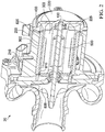
- FIG. 1 shows a charging device 10 with a shaft 100, a compressor wheel 600 arranged on shaft 100, a stator housing 200, and a stator 300.
- Stator 300 is arranged within stator housing 200.
- Charging device 10 further comprises a rotor 500 arranged on shaft 100 and an axially extending cooling channel 400 for accommodating a coolant.
- Cooling channel 400 is provided between stator housing 200 and stator 300 are runs in a ring shape or in a cylindrical shape along the circumference of stator 300. Cooling channel 400 is supplied, via an inlet and an outlet, with coolant, which circulates in cooling channel 400 for cooling the stator (the ring-shaped or cylindrical configuration of cooling channel 400 and the supply via inlet and outlet applies for all embodiments of the charging device described in the following).
- a split tube 700 is arranged between rotor 500 and stator 300.
- a first seal 810 is provided in the axial direction between stator housing 200 and a first end of stator 300 and a second seal 820 is provided in the axial direction between stator housing 200 and a first end of split tube 700.
- the first end of the stator is the proximal end of stator 300 relative to compressor wheel 600, i.e. the end of stator 300 located closer to compressor wheel 600 than the proximal second end of stator 300.
- the first end of split tube 700 is a distal end of split tube 700 relative to compressor wheel 600.
- the embodiment of charging device 10 shown in Figure 1 additionally has a third seal 830 in the axial direction between stator housing 200 and a proximal second end of split tube 700, such that a dry compartment is created between first seal 810 and third seal 830.
- the dry compartment is used for the dry accommodation of an electrical connection of the stator to a control unit, which may be provided, for example, between a housing wall and a housing cover or between a housing wall and a compressor housing back wall.
- Charging device 10 according to the invention has the advantage that stator 300 is directly flushed with cooling fluid and thus an efficient cooling of stator 300 is facilitated.
- stator housing 200 may be produced in a die casting method, as no cooling channels need to be provided in stator housing 200. This means that a smaller design of stator housing 200 may be realized, and a reduction of the material costs as well as a simpler and more cost-efficient production of charging device 10.
- charging device 10 according to the invention facilitates a good cooling of the rotor on the basis of split tube 700.
- split tube 700 may be blackened in order to better be able to accommodate the heat of rotor 500 via radiation, by which means the indirect cooling of rotor 500 is more efficient.
- cooling channel 400 extends radially inward in the area of the distal second end of stator 300 between stator 300 and stator housing 200 in the direction of shaft 100.
- the area of cooling channel 400 extending radially inward may thereby reach up to a bearing seat of a bearing of shaft 100, by which means the bearing seat is cooled.
- the bearing is also indirectly cooled in this way.
- Stator housing 200 in Figure 1 comprises a main body 210 and a cover 220.
- Second seal 820 is arranged between split tube 400 and cover 220 of stator housing 200.
- cover 220 has a projection 225 and seal 820 is arranged between this projection 225 and split tube 700.
- the projection defines on its inner side a bearing seat for a bearing for mounting shaft 100. Due to this type of arrangement, the cooling channel may be configured up to the bearing seat and thus the coolant circulating there may also cool the bearing seat and additionally indirectly the bearing.
- Stator 300 of the charging device according to the invention may, for example, comprise windings and sealing compound.
- First seal 810 may be integrated directly into the sealing compound or be formed from the sealing compound in a configuration of this type.
- the walls of cooling channel 400 are formed directly from stator housing 200 and the sealing compound of stator 300. This may be facilitated by the use of a fluid-tight, in particular a water-tight sealing compound.
- third seal 830 may also be omitted, since a dry compartment may be formed radially with first seal 810 with an axial limitation by the fluid-tight sealing compound of stator 300.
- a fluid-tight membrane may be provided (not shown in Figure 1 ), which surrounds stator 300. Then the walls of cooling channel 400 are formed by the membrane and stator housing 200.
- FIG. 2 shows a second embodiment of charging device 20 not forming part of the invention.
- Charging device 20 has in turn a shaft 100, a compressor wheel 600 arranged on shaft 100, a stator housing 200, and a stator 300.
- Charging device 20 also comprises a rotor 500 arranged on shaft 100 and a cooling channel 400 extending axially for accommodating a coolant.
- charging device 20 of Figure 2 does not have a split tube.
- a separation tube 900 is arranged for this purpose between stator 300 and stator housing 200 so that cooling channel 400 is formed in the radial direction between separation tube 900 and stator housing 200.
- separation tube 900 and additionally split tube 400 shown in Figure 1 may be provided.
- stator housing 200 may be produced in a die casting method in this embodiment, as no cooling channels need to be provided in stator housing 200.
- Separation tube 900 itself may be manufactured in a simple way, for example, by deep drawing. In sum, this means in turn a smaller design of stator housing 200 and a reduction of the material costs as well as a simpler and more cost-efficient production of charging device 20 at a simultaneously efficient stator cooling.
- Figure 2 shows that a first seal 810 is provided between stator housing 200 and a first (proximal with respect to compressor wheel 600) end of separation tube 900, and a second seal 820 is provided between stator housing 200 and a (distal with respect to compressor wheel 600) end of separation tube 900.
- First seal 810 is arranged in turn in the area of the radially outer circumference of stator 300 so that a dry compartment is created radially inward of seal 810 in the area of the proximal end of stator 300.
- the longitudinal section of separation tube 900 is L-shaped. Radially arranged leg of separation tube 900 extends radially outward. Second seal 820 is arranged between the radial end of radially extending leg and stator housing 200 (see Figure 2 ). In Figure 2 , seal 820 is arranged between leg and cover 220 of housing 200. Seal 820 may equally be arranged between leg and main body 210 of housing 200 as well. According to the invention, the radially extending leg of separation tube 900 extends radially inward.
- Second seal 820 is then arranged between the radial end of the radially extending leg and stator housing 200 such that cooling channel 400 may extend radially inward between separation tube 900 and stator housing 200 in the direction of shaft 100.
- seal 820 may be arranged between the leg and projection 225 of stator housing 200 which defines a bearing seat for a bearing for mounting shaft 100.
- Stator housing 200 as shown in Figure 2 , comprises in turn main body 210 and cover 220.
- Projection 225 is a part of cover 220, so that second seal 820 may also be arranged between separation tube 900 and cover 220 in an alternative that is not shown.
- Stator 300 may comprise windings and sealing compound.
- the windings of stator 300 may be arranged in separation tube 900 during production and may be cast therein so that a fixed connection is created between stator 300 and separation tube 900 after the die casting.
- process steps and the connection of the stator to the separation tube may be omitted and the combination made from the stator with separation tube may also be mounted as a module.
- separation tube 900 may be advantageous to configure separation tube 900 as a deep drawn component and thus to manufacture it in an advantageous way.
- a third embodiment of the charging device may likewise have a shaft 100, a compressor wheel 600 arranged on shaft 100, a stator housing 200, and a stator 300.
- the stator in turn has windings and sealing compound.
- the charging device comprises rotor 500 arranged on shaft 100 and an axially extending cooling channel 400 for accommodating a coolant between stator housing 200 and stator 300.
- a first seal 810 is provided in the axial direction between stator housing 200 and a first end (proximal with respect to compressor wheel 600) of stator 300, and a second seal is provided in the axial direction between stator housing 200 and a second end (distal with respect to compressor wheel 600) of stator 300.
- there is no separation tube and no split tube and the seals are arranged on both sides directly between stator housing 200 and stator 300 so that the walls of cooling channel 400 are formed directly by stator housing 200 and the sealing compound of stator 300. This may in turn be facilitated, for example, by the use of a fluid-tight, in particular a water-tight sealing compound.
- a fluid-tight, in particular a water-tight membrane surrounds stator 300. Then the walls of cooling channel 400 are formed from the membrane and stator housing 200.
- the stator is directly flushed by cooling fluid and thus an efficient cooling of the stator is facilitated.
- the stator housing may be produced in a die casting method, as no cooling channels need to be provided in the stator housing. This means in turn that a smaller design of the stator housing may be realized, and that a reduction of the material costs as well as a simpler and more cost-efficient production of the charging device.
- the first and/or the second seal may be directly integrated into the sealing compound or be formed from the sealing compound in this embodiment.
- the second end of stator 300 (the distal end of stator 300 when viewed from compressor wheel 600) and the second seal may be arranged in the area of the radially inner circumference of the second end of stator 300 such that cooling channel 400 extends radially inward between stator 300 and stator housing 200 in the direction of shaft 100.
- the area of cooling channel 400 extending radially inward may thereby extend up to a bearing seat of a bearing of shaft 100, by which means the bearing seat is cooled.
- the bearing is also indirectly cooled in this way.
- First seal 810 may in turn be arranged in the area of the radially outer circumference of stator 300, so that a dry compartment is created radially within seal 810 in the area of the first end of stator 300 (proximal with respect to compressor wheel 600).
- Stator housing 200 may also comprise in this embodiment a main body 210 and a cover 220, so that second seal 820 may be arranged between stator 300 and cover 220, in particular between projection 225 of cover 220, which defines the bearing seat for the bearing for mounting shaft 100.
Landscapes
- Engineering & Computer Science (AREA)
- Mechanical Engineering (AREA)
- General Engineering & Computer Science (AREA)
- Power Engineering (AREA)
- Chemical & Material Sciences (AREA)
- Combustion & Propulsion (AREA)
- Physics & Mathematics (AREA)
- Thermal Sciences (AREA)
- Motor Or Generator Cooling System (AREA)
- Structures Of Non-Positive Displacement Pumps (AREA)
Claims (11)
- Dispositif d'alimentation (10) pour un moteur à combustion interne, comportant :un arbre (100) ;une roue de compresseur (600) disposée sur l'arbre (100) ;un carter de stator (200);un moteur électrique comportant un stator (300) et un rotor (500), le stator (300) étant disposé à l'intérieur du carter de stator (200);le rotor (500) disposé sur l'arbre (100) ; etun canal de refroidissement (400) s'étendant axialement pour accueillir un agent de refroidissement entre le carter de stator (200) et le stator (300) ;caractérisé en ce qu'un tube divisé (700) est placé entre le rotor (500) et le stator (300),un premier joint (810) étant placé dans la direction axiale entre le carter de stator (200) et une première extrémité du stator (300) et un deuxième joint (820) étant placé dans la direction axiale entre le carter de stator (200) et une première extrémité du tube divisé (700), ladite première extrémité du tube divisé étant axialement distale par rapport à la première extrémité du stator (300).
- Dispositif d'alimentation selon la revendication 1, caractérisé en ce qu'un troisième joint (830) est placé dans la direction axiale entre le carter de stator (200) et une deuxième extrémité du tube divisé (700) de telle façon qu'un compartiment sec est créé entre le premier joint (810) et le troisième joint (830).
- Dispositif d'alimentation selon la revendication 1 ou la revendication 2, caractérisé en ce qu'une deuxième extrémité du stator (300), qui est l'extrémité distale du stator (300) lorsqu'elle est vue depuis la roue de compresseur (600), est opposée à la première extrémité du stator (300), et en ce que le canal de refroidissement (400) s'étend radialement vers l'intérieur dans la zone de la deuxième extrémité du stator (300) entre le stator (300) et le carter de stator (200) dans la direction de l'arbre (100).
- Dispositif d'alimentation selon l'une quelconque des revendications précédentes, caractérisé en ce que le stator (300) comporte bobines et composé d'étanchéité, le premier joint (810) étant optionnellement directement intégré dans le composé d'étanchéité ou étant formé du composé d'étanchéité.
- Dispositif d'alimentation selon la revendication 4, caractérisé en ce que les parois du canal de refroidissement (400) sont formées directement par le carter de stator (200) et le composé d'étanchéité du stator (300), ou en ce qu'une membrane étanche aux fluides, en particulier étanche à l'eau, entoure le stator (300) et en ce que les parois du canal de refroidissement (400) sont formées de la membrane et du carter de stator (200).
- Dispositif d'alimentation selon l'une quelconque des revendications précédentes, caractérisé en ce que le carter de stator (200) comporte un corps principal (210) et un couvercle (220), le deuxième joint (820) étant en particulier disposé entre le tube divisé (700) et le couvercle (220), en particulier une saillie (225) du couvercle (220) définissant un logement de roulement pour un roulement servant à monter l'arbre (100).
- Dispositif d'alimentation (20) pour un moteur à combustion interne, comportant :un arbre (100) ;une roue de compresseur (600) disposée sur l'arbre (100) ;un carter de stator (200);un moteur électrique comportant un stator (300) et un rotor (500), le stator (300) étant disposé à l'intérieur du carter de stator (200);le rotor (500) disposé sur l'arbre (100) ;un canal de refroidissement (400) s'étendant axialement pour accueillir un agent de refroidissement ; etun tube de séparation (900) qui est disposé entre le stator (300) et le carter de stator (200) de telle façon que le canal de refroidissement (400) est formé dans la direction radiale entre le tube de séparation (900) et le carter de stator (200); un premier joint (810) étant placé entre le carter de stator (200) et une première extrémité du tube de séparation (900); caractérisé en ce que la coupe longitudinale du tube de séparation (900) est en forme de L et en ce qu'une branche disposée radialement du tube de séparation (900) s'étende radialement vers l'intérieur, et un deuxième joint (820) est disposé entre l'extrémité radiale de la branche s'étendant radialement et le carter de stator (200), en particulier une saillie du carter (200) de stator définissant un logement de roulement pour un roulement servant à monter l'arbre (100).
- Dispositif d'alimentation selon la revendication 7, caractérisé en ce que le premier joint (810) est disposé dans la zone de l'extrémité proximale du stator (300), lorsqu'elle est vue depuis la roue de compresseur (600), et dans la zone de la circonférence radialement extérieure du stator (300) de telle façon qu'un compartiment sec est créé radialement à l'intérieur du joint (810) dans la zone de l'extrémité proximale du stator (300).
- Dispositif d'alimentation selon la revendication 7, caractérisé en ce que le carter de stator (200) comporte un corps principal (210) et un couvercle (220), en particulier la saillie (225) fait partie du couvercle (220) et le deuxième joint (820) est disposé entre le tube (900) de séparation et le couvercle (220).
- Dispositif d'alimentation selon l'une quelconque des revendications 7 à 9, caractérisé en ce que le stator (300) comporte bobines et composé d'étanchéité, et en ce que les bobines du stator (300) sont disposés dans le tube de séparation (900) pendant la fabrication et sont moulés dans celui-ci de telle façon qu'une liaison fixe soit créée entre le stator (300) et le tube de séparation (900).
- Dispositif d'alimentation selon l'une quelconque des revendications 7 à 10, caractérisé en ce que le tube de séparation (900) est une pièce emboutie.
Applications Claiming Priority (2)
| Application Number | Priority Date | Filing Date | Title |
|---|---|---|---|
| DE102016207764 | 2016-05-04 | ||
| PCT/US2017/029634 WO2017192336A1 (fr) | 2016-05-04 | 2017-04-26 | Dispositif de charge électrique à refroidissement par fluide |
Publications (2)
| Publication Number | Publication Date |
|---|---|
| EP3452707A1 EP3452707A1 (fr) | 2019-03-13 |
| EP3452707B1 true EP3452707B1 (fr) | 2021-03-17 |
Family
ID=58671948
Family Applications (1)
| Application Number | Title | Priority Date | Filing Date |
|---|---|---|---|
| EP17721947.4A Active EP3452707B1 (fr) | 2016-05-04 | 2017-04-26 | Dispositif de charge électrique à refroidissement par fluide |
Country Status (3)
| Country | Link |
|---|---|
| US (1) | US10971974B2 (fr) |
| EP (1) | EP3452707B1 (fr) |
| WO (1) | WO2017192336A1 (fr) |
Families Citing this family (4)
| Publication number | Priority date | Publication date | Assignee | Title |
|---|---|---|---|---|
| KR20180134348A (ko) * | 2016-04-12 | 2018-12-18 | 티엠4 인코포레이티드 | 밀봉된 고정자를 가진 액체 냉각 전기 머신 |
| IT201800009201A1 (it) * | 2018-10-05 | 2020-04-05 | Ind Saleri Italo Spa | Gruppo pompa |
| EP3726063B1 (fr) | 2019-04-15 | 2021-11-24 | BorgWarner Inc. | Compresseur à commande électrique et à refroidissement par fluide et logement de stator correspondant |
| DE102020129525A1 (de) * | 2020-11-10 | 2022-05-12 | Dr. Ing. H.C. F. Porsche Aktiengesellschaft | Abgasturbolader |
Family Cites Families (8)
| Publication number | Priority date | Publication date | Assignee | Title |
|---|---|---|---|---|
| DE19545561A1 (de) * | 1995-12-07 | 1997-06-12 | Pierburg Ag | Pumpe-Motoreinheit |
| DE69927327T3 (de) * | 1998-07-28 | 2009-09-17 | Aisin Seiki K.K., Kariya | Kühlungseinrichtung für Brennkraftmaschinen |
| DE19938624C2 (de) | 1999-08-14 | 2001-06-07 | Daimler Chrysler Ag | Abgasturbolader |
| DE10063321A1 (de) | 2000-12-19 | 2002-06-20 | Gfas Mbh Ges Fuer Aufladetechn | Elektrisch angetriebener Strömungsverdichter |
| KR20090039770A (ko) | 2006-08-18 | 2009-04-22 | 가부시키가이샤 아이에이치아이 | 전동 과급기 |
| WO2011022557A2 (fr) * | 2009-08-19 | 2011-02-24 | Aspen Motion Technologies, Inc. D/B/A | Ensemble pompe à entraînement magnétique avec moteur intégré |
| KR101072327B1 (ko) * | 2009-11-19 | 2011-10-11 | 현대자동차주식회사 | 전기식 워터 펌프 |
| US8920142B2 (en) * | 2012-02-28 | 2014-12-30 | Hamilton Sundstrand Corporation | Wet rotor pump motor stator sealing liner |
-
2017
- 2017-04-26 US US16/099,110 patent/US10971974B2/en active Active
- 2017-04-26 EP EP17721947.4A patent/EP3452707B1/fr active Active
- 2017-04-26 WO PCT/US2017/029634 patent/WO2017192336A1/fr not_active Ceased
Non-Patent Citations (1)
| Title |
|---|
| None * |
Also Published As
| Publication number | Publication date |
|---|---|
| EP3452707A1 (fr) | 2019-03-13 |
| US10971974B2 (en) | 2021-04-06 |
| WO2017192336A1 (fr) | 2017-11-09 |
| US20190157945A1 (en) | 2019-05-23 |
Similar Documents
| Publication | Publication Date | Title |
|---|---|---|
| US10364761B2 (en) | Turbocharger | |
| US8157544B2 (en) | Motor driven supercharger with motor/generator cooling efficacy | |
| US9470231B2 (en) | Electrically assisted turbocharger | |
| CN101688469B (zh) | 带电动机的增压机 | |
| CN104736814B (zh) | 带电动机的增压器和具有带电动机的增压器的发动机装置 | |
| EP3452707B1 (fr) | Dispositif de charge électrique à refroidissement par fluide | |
| JP4697492B2 (ja) | 電動過給機 | |
| JP4605380B2 (ja) | 電動過給機 | |
| CN107250505B (zh) | 用于驱动装置的增压器、尤其是废气涡轮增压器以及相应的驱动装置 | |
| US20130043747A1 (en) | Electric Machine Cooling | |
| KR20180037072A (ko) | 과급기 및 모터 냉각 방법 | |
| US20150322851A1 (en) | Fluid cooled electrically-assisted turborcharger | |
| US20250030301A1 (en) | Electric motor | |
| US12025016B2 (en) | Compressor housing | |
| AU2014322794B2 (en) | An electric or hybrid vehicle using motor-generator having shaft with centrifugal fan blades for cooling | |
| US10837363B2 (en) | Systems for an electric turbocharger | |
| US11929643B2 (en) | Compressor motor including active stator cooling | |
| CN116941165A (zh) | 旋转电机 | |
| CN112789410B (zh) | 用于机动车内燃机的进气管段的压缩机、用于机动车的内燃机以及机动车 | |
| WO2013176853A1 (fr) | Enveloppe de stator refroidie par un fluide pour turbocompresseur à assistance électrique | |
| JP2019105233A (ja) | 過給機 | |
| CN120344771A (zh) | 气体供给装置和用于组装气体供给装置的方法 | |
| CN114508495A (zh) | 用于电子增压装置的马达冷却系统 | |
| KR20070017034A (ko) | 전동 과급기 |
Legal Events
| Date | Code | Title | Description |
|---|---|---|---|
| STAA | Information on the status of an ep patent application or granted ep patent |
Free format text: STATUS: UNKNOWN |
|
| STAA | Information on the status of an ep patent application or granted ep patent |
Free format text: STATUS: THE INTERNATIONAL PUBLICATION HAS BEEN MADE |
|
| PUAI | Public reference made under article 153(3) epc to a published international application that has entered the european phase |
Free format text: ORIGINAL CODE: 0009012 |
|
| STAA | Information on the status of an ep patent application or granted ep patent |
Free format text: STATUS: REQUEST FOR EXAMINATION WAS MADE |
|
| 17P | Request for examination filed |
Effective date: 20181128 |
|
| AK | Designated contracting states |
Kind code of ref document: A1 Designated state(s): AL AT BE BG CH CY CZ DE DK EE ES FI FR GB GR HR HU IE IS IT LI LT LU LV MC MK MT NL NO PL PT RO RS SE SI SK SM TR |
|
| AX | Request for extension of the european patent |
Extension state: BA ME |
|
| DAV | Request for validation of the european patent (deleted) | ||
| DAX | Request for extension of the european patent (deleted) | ||
| GRAP | Despatch of communication of intention to grant a patent |
Free format text: ORIGINAL CODE: EPIDOSNIGR1 |
|
| STAA | Information on the status of an ep patent application or granted ep patent |
Free format text: STATUS: GRANT OF PATENT IS INTENDED |
|
| INTG | Intention to grant announced |
Effective date: 20200330 |
|
| GRAJ | Information related to disapproval of communication of intention to grant by the applicant or resumption of examination proceedings by the epo deleted |
Free format text: ORIGINAL CODE: EPIDOSDIGR1 |
|
| STAA | Information on the status of an ep patent application or granted ep patent |
Free format text: STATUS: REQUEST FOR EXAMINATION WAS MADE |
|
| INTC | Intention to grant announced (deleted) | ||
| GRAS | Grant fee paid |
Free format text: ORIGINAL CODE: EPIDOSNIGR3 |
|
| STAA | Information on the status of an ep patent application or granted ep patent |
Free format text: STATUS: GRANT OF PATENT IS INTENDED |
|
| GRAP | Despatch of communication of intention to grant a patent |
Free format text: ORIGINAL CODE: EPIDOSNIGR1 |
|
| INTG | Intention to grant announced |
Effective date: 20201013 |
|
| GRAA | (expected) grant |
Free format text: ORIGINAL CODE: 0009210 |
|
| STAA | Information on the status of an ep patent application or granted ep patent |
Free format text: STATUS: THE PATENT HAS BEEN GRANTED |
|
| AK | Designated contracting states |
Kind code of ref document: B1 Designated state(s): AL AT BE BG CH CY CZ DE DK EE ES FI FR GB GR HR HU IE IS IT LI LT LU LV MC MK MT NL NO PL PT RO RS SE SI SK SM TR |
|
| REG | Reference to a national code |
Ref country code: GB Ref legal event code: FG4D |
|
| REG | Reference to a national code |
Ref country code: CH Ref legal event code: EP |
|
| REG | Reference to a national code |
Ref country code: DE Ref legal event code: R096 Ref document number: 602017034729 Country of ref document: DE |
|
| REG | Reference to a national code |
Ref country code: IE Ref legal event code: FG4D |
|
| REG | Reference to a national code |
Ref country code: AT Ref legal event code: REF Ref document number: 1372440 Country of ref document: AT Kind code of ref document: T Effective date: 20210415 |
|
| REG | Reference to a national code |
Ref country code: LT Ref legal event code: MG9D |
|
| PG25 | Lapsed in a contracting state [announced via postgrant information from national office to epo] |
Ref country code: HR Free format text: LAPSE BECAUSE OF FAILURE TO SUBMIT A TRANSLATION OF THE DESCRIPTION OR TO PAY THE FEE WITHIN THE PRESCRIBED TIME-LIMIT Effective date: 20210317 Ref country code: FI Free format text: LAPSE BECAUSE OF FAILURE TO SUBMIT A TRANSLATION OF THE DESCRIPTION OR TO PAY THE FEE WITHIN THE PRESCRIBED TIME-LIMIT Effective date: 20210317 Ref country code: GR Free format text: LAPSE BECAUSE OF FAILURE TO SUBMIT A TRANSLATION OF THE DESCRIPTION OR TO PAY THE FEE WITHIN THE PRESCRIBED TIME-LIMIT Effective date: 20210618 Ref country code: NO Free format text: LAPSE BECAUSE OF FAILURE TO SUBMIT A TRANSLATION OF THE DESCRIPTION OR TO PAY THE FEE WITHIN THE PRESCRIBED TIME-LIMIT Effective date: 20210617 Ref country code: BG Free format text: LAPSE BECAUSE OF FAILURE TO SUBMIT A TRANSLATION OF THE DESCRIPTION OR TO PAY THE FEE WITHIN THE PRESCRIBED TIME-LIMIT Effective date: 20210617 |
|
| REG | Reference to a national code |
Ref country code: AT Ref legal event code: MK05 Ref document number: 1372440 Country of ref document: AT Kind code of ref document: T Effective date: 20210317 |
|
| REG | Reference to a national code |
Ref country code: NL Ref legal event code: MP Effective date: 20210317 |
|
| PG25 | Lapsed in a contracting state [announced via postgrant information from national office to epo] |
Ref country code: RS Free format text: LAPSE BECAUSE OF FAILURE TO SUBMIT A TRANSLATION OF THE DESCRIPTION OR TO PAY THE FEE WITHIN THE PRESCRIBED TIME-LIMIT Effective date: 20210317 Ref country code: LV Free format text: LAPSE BECAUSE OF FAILURE TO SUBMIT A TRANSLATION OF THE DESCRIPTION OR TO PAY THE FEE WITHIN THE PRESCRIBED TIME-LIMIT Effective date: 20210317 Ref country code: SE Free format text: LAPSE BECAUSE OF FAILURE TO SUBMIT A TRANSLATION OF THE DESCRIPTION OR TO PAY THE FEE WITHIN THE PRESCRIBED TIME-LIMIT Effective date: 20210317 |
|
| PG25 | Lapsed in a contracting state [announced via postgrant information from national office to epo] |
Ref country code: NL Free format text: LAPSE BECAUSE OF FAILURE TO SUBMIT A TRANSLATION OF THE DESCRIPTION OR TO PAY THE FEE WITHIN THE PRESCRIBED TIME-LIMIT Effective date: 20210317 |
|
| PG25 | Lapsed in a contracting state [announced via postgrant information from national office to epo] |
Ref country code: LT Free format text: LAPSE BECAUSE OF FAILURE TO SUBMIT A TRANSLATION OF THE DESCRIPTION OR TO PAY THE FEE WITHIN THE PRESCRIBED TIME-LIMIT Effective date: 20210317 Ref country code: CZ Free format text: LAPSE BECAUSE OF FAILURE TO SUBMIT A TRANSLATION OF THE DESCRIPTION OR TO PAY THE FEE WITHIN THE PRESCRIBED TIME-LIMIT Effective date: 20210317 Ref country code: EE Free format text: LAPSE BECAUSE OF FAILURE TO SUBMIT A TRANSLATION OF THE DESCRIPTION OR TO PAY THE FEE WITHIN THE PRESCRIBED TIME-LIMIT Effective date: 20210317 Ref country code: AT Free format text: LAPSE BECAUSE OF FAILURE TO SUBMIT A TRANSLATION OF THE DESCRIPTION OR TO PAY THE FEE WITHIN THE PRESCRIBED TIME-LIMIT Effective date: 20210317 Ref country code: SM Free format text: LAPSE BECAUSE OF FAILURE TO SUBMIT A TRANSLATION OF THE DESCRIPTION OR TO PAY THE FEE WITHIN THE PRESCRIBED TIME-LIMIT Effective date: 20210317 |
|
| PG25 | Lapsed in a contracting state [announced via postgrant information from national office to epo] |
Ref country code: IS Free format text: LAPSE BECAUSE OF FAILURE TO SUBMIT A TRANSLATION OF THE DESCRIPTION OR TO PAY THE FEE WITHIN THE PRESCRIBED TIME-LIMIT Effective date: 20210717 Ref country code: PT Free format text: LAPSE BECAUSE OF FAILURE TO SUBMIT A TRANSLATION OF THE DESCRIPTION OR TO PAY THE FEE WITHIN THE PRESCRIBED TIME-LIMIT Effective date: 20210719 Ref country code: PL Free format text: LAPSE BECAUSE OF FAILURE TO SUBMIT A TRANSLATION OF THE DESCRIPTION OR TO PAY THE FEE WITHIN THE PRESCRIBED TIME-LIMIT Effective date: 20210317 Ref country code: RO Free format text: LAPSE BECAUSE OF FAILURE TO SUBMIT A TRANSLATION OF THE DESCRIPTION OR TO PAY THE FEE WITHIN THE PRESCRIBED TIME-LIMIT Effective date: 20210317 Ref country code: SK Free format text: LAPSE BECAUSE OF FAILURE TO SUBMIT A TRANSLATION OF THE DESCRIPTION OR TO PAY THE FEE WITHIN THE PRESCRIBED TIME-LIMIT Effective date: 20210317 |
|
| REG | Reference to a national code |
Ref country code: DE Ref legal event code: R097 Ref document number: 602017034729 Country of ref document: DE |
|
| PG25 | Lapsed in a contracting state [announced via postgrant information from national office to epo] |
Ref country code: LU Free format text: LAPSE BECAUSE OF NON-PAYMENT OF DUE FEES Effective date: 20210426 |
|
| REG | Reference to a national code |
Ref country code: BE Ref legal event code: MM Effective date: 20210430 |
|
| PLBE | No opposition filed within time limit |
Free format text: ORIGINAL CODE: 0009261 |
|
| STAA | Information on the status of an ep patent application or granted ep patent |
Free format text: STATUS: NO OPPOSITION FILED WITHIN TIME LIMIT |
|
| PG25 | Lapsed in a contracting state [announced via postgrant information from national office to epo] |
Ref country code: ES Free format text: LAPSE BECAUSE OF FAILURE TO SUBMIT A TRANSLATION OF THE DESCRIPTION OR TO PAY THE FEE WITHIN THE PRESCRIBED TIME-LIMIT Effective date: 20210317 Ref country code: DK Free format text: LAPSE BECAUSE OF FAILURE TO SUBMIT A TRANSLATION OF THE DESCRIPTION OR TO PAY THE FEE WITHIN THE PRESCRIBED TIME-LIMIT Effective date: 20210317 Ref country code: CH Free format text: LAPSE BECAUSE OF NON-PAYMENT OF DUE FEES Effective date: 20210430 Ref country code: AL Free format text: LAPSE BECAUSE OF FAILURE TO SUBMIT A TRANSLATION OF THE DESCRIPTION OR TO PAY THE FEE WITHIN THE PRESCRIBED TIME-LIMIT Effective date: 20210317 Ref country code: MC Free format text: LAPSE BECAUSE OF FAILURE TO SUBMIT A TRANSLATION OF THE DESCRIPTION OR TO PAY THE FEE WITHIN THE PRESCRIBED TIME-LIMIT Effective date: 20210317 Ref country code: LI Free format text: LAPSE BECAUSE OF NON-PAYMENT OF DUE FEES Effective date: 20210430 |
|
| 26N | No opposition filed |
Effective date: 20211220 |
|
| GBPC | Gb: european patent ceased through non-payment of renewal fee |
Effective date: 20210617 |
|
| PG25 | Lapsed in a contracting state [announced via postgrant information from national office to epo] |
Ref country code: SI Free format text: LAPSE BECAUSE OF FAILURE TO SUBMIT A TRANSLATION OF THE DESCRIPTION OR TO PAY THE FEE WITHIN THE PRESCRIBED TIME-LIMIT Effective date: 20210317 |
|
| PG25 | Lapsed in a contracting state [announced via postgrant information from national office to epo] |
Ref country code: IT Free format text: LAPSE BECAUSE OF FAILURE TO SUBMIT A TRANSLATION OF THE DESCRIPTION OR TO PAY THE FEE WITHIN THE PRESCRIBED TIME-LIMIT Effective date: 20210317 Ref country code: IE Free format text: LAPSE BECAUSE OF NON-PAYMENT OF DUE FEES Effective date: 20210426 Ref country code: GB Free format text: LAPSE BECAUSE OF NON-PAYMENT OF DUE FEES Effective date: 20210617 |
|
| PG25 | Lapsed in a contracting state [announced via postgrant information from national office to epo] |
Ref country code: IS Free format text: LAPSE BECAUSE OF FAILURE TO SUBMIT A TRANSLATION OF THE DESCRIPTION OR TO PAY THE FEE WITHIN THE PRESCRIBED TIME-LIMIT Effective date: 20210717 Ref country code: FR Free format text: LAPSE BECAUSE OF NON-PAYMENT OF DUE FEES Effective date: 20210517 |
|
| PG25 | Lapsed in a contracting state [announced via postgrant information from national office to epo] |
Ref country code: BE Free format text: LAPSE BECAUSE OF NON-PAYMENT OF DUE FEES Effective date: 20210430 |
|
| P01 | Opt-out of the competence of the unified patent court (upc) registered |
Effective date: 20230327 |
|
| PG25 | Lapsed in a contracting state [announced via postgrant information from national office to epo] |
Ref country code: CY Free format text: LAPSE BECAUSE OF FAILURE TO SUBMIT A TRANSLATION OF THE DESCRIPTION OR TO PAY THE FEE WITHIN THE PRESCRIBED TIME-LIMIT Effective date: 20210317 |
|
| PG25 | Lapsed in a contracting state [announced via postgrant information from national office to epo] |
Ref country code: HU Free format text: LAPSE BECAUSE OF FAILURE TO SUBMIT A TRANSLATION OF THE DESCRIPTION OR TO PAY THE FEE WITHIN THE PRESCRIBED TIME-LIMIT; INVALID AB INITIO Effective date: 20170426 |
|
| PG25 | Lapsed in a contracting state [announced via postgrant information from national office to epo] |
Ref country code: MK Free format text: LAPSE BECAUSE OF FAILURE TO SUBMIT A TRANSLATION OF THE DESCRIPTION OR TO PAY THE FEE WITHIN THE PRESCRIBED TIME-LIMIT Effective date: 20210317 |
|
| PG25 | Lapsed in a contracting state [announced via postgrant information from national office to epo] |
Ref country code: MT Free format text: LAPSE BECAUSE OF FAILURE TO SUBMIT A TRANSLATION OF THE DESCRIPTION OR TO PAY THE FEE WITHIN THE PRESCRIBED TIME-LIMIT Effective date: 20210317 |
|
| PGFP | Annual fee paid to national office [announced via postgrant information from national office to epo] |
Ref country code: DE Payment date: 20250317 Year of fee payment: 9 |
|
| PG25 | Lapsed in a contracting state [announced via postgrant information from national office to epo] |
Ref country code: TR Free format text: LAPSE BECAUSE OF FAILURE TO SUBMIT A TRANSLATION OF THE DESCRIPTION OR TO PAY THE FEE WITHIN THE PRESCRIBED TIME-LIMIT Effective date: 20210317 |