EP3452708B1 - Composant de rétention pour dispositif de turbomachines - Google Patents
Composant de rétention pour dispositif de turbomachines Download PDFInfo
- Publication number
- EP3452708B1 EP3452708B1 EP16901146.7A EP16901146A EP3452708B1 EP 3452708 B1 EP3452708 B1 EP 3452708B1 EP 16901146 A EP16901146 A EP 16901146A EP 3452708 B1 EP3452708 B1 EP 3452708B1
- Authority
- EP
- European Patent Office
- Prior art keywords
- conduit
- stator
- fluid
- product
- bearing
- Prior art date
- Legal status (The legal status is an assumption and is not a legal conclusion. Google has not performed a legal analysis and makes no representation as to the accuracy of the status listed.)
- Active
Links
Images


Classifications
-
- F—MECHANICAL ENGINEERING; LIGHTING; HEATING; WEAPONS; BLASTING
- F04—POSITIVE - DISPLACEMENT MACHINES FOR LIQUIDS; PUMPS FOR LIQUIDS OR ELASTIC FLUIDS
- F04D—NON-POSITIVE-DISPLACEMENT PUMPS
- F04D29/00—Details, component parts, or accessories
- F04D29/05—Shafts or bearings, or assemblies thereof, specially adapted for elastic fluid pumps
- F04D29/056—Bearings
-
- F—MECHANICAL ENGINEERING; LIGHTING; HEATING; WEAPONS; BLASTING
- F02—COMBUSTION ENGINES; HOT-GAS OR COMBUSTION-PRODUCT ENGINE PLANTS
- F02B—INTERNAL-COMBUSTION PISTON ENGINES; COMBUSTION ENGINES IN GENERAL
- F02B33/00—Engines characterised by provision of pumps for charging or scavenging
- F02B33/32—Engines with pumps other than of reciprocating-piston type
- F02B33/34—Engines with pumps other than of reciprocating-piston type with rotary pumps
- F02B33/40—Engines with pumps other than of reciprocating-piston type with rotary pumps of non-positive-displacement type
-
- F—MECHANICAL ENGINEERING; LIGHTING; HEATING; WEAPONS; BLASTING
- F02—COMBUSTION ENGINES; HOT-GAS OR COMBUSTION-PRODUCT ENGINE PLANTS
- F02B—INTERNAL-COMBUSTION PISTON ENGINES; COMBUSTION ENGINES IN GENERAL
- F02B39/00—Component parts, details, or accessories relating to, driven charging or scavenging pumps, not provided for in groups F02B33/00 - F02B37/00
- F02B39/02—Drives of pumps; Varying pump drive gear ratio
- F02B39/08—Non-mechanical drives, e.g. fluid drives having variable gear ratio
- F02B39/10—Non-mechanical drives, e.g. fluid drives having variable gear ratio electric
-
- F—MECHANICAL ENGINEERING; LIGHTING; HEATING; WEAPONS; BLASTING
- F02—COMBUSTION ENGINES; HOT-GAS OR COMBUSTION-PRODUCT ENGINE PLANTS
- F02B—INTERNAL-COMBUSTION PISTON ENGINES; COMBUSTION ENGINES IN GENERAL
- F02B39/00—Component parts, details, or accessories relating to, driven charging or scavenging pumps, not provided for in groups F02B33/00 - F02B37/00
- F02B39/14—Lubrication of pumps; Safety measures therefor
-
- F—MECHANICAL ENGINEERING; LIGHTING; HEATING; WEAPONS; BLASTING
- F04—POSITIVE - DISPLACEMENT MACHINES FOR LIQUIDS; PUMPS FOR LIQUIDS OR ELASTIC FLUIDS
- F04D—NON-POSITIVE-DISPLACEMENT PUMPS
- F04D25/00—Pumping installations or systems
- F04D25/02—Units comprising pumps and their driving means
- F04D25/06—Units comprising pumps and their driving means the pump being electrically driven
-
- F—MECHANICAL ENGINEERING; LIGHTING; HEATING; WEAPONS; BLASTING
- F04—POSITIVE - DISPLACEMENT MACHINES FOR LIQUIDS; PUMPS FOR LIQUIDS OR ELASTIC FLUIDS
- F04D—NON-POSITIVE-DISPLACEMENT PUMPS
- F04D25/00—Pumping installations or systems
- F04D25/02—Units comprising pumps and their driving means
- F04D25/06—Units comprising pumps and their driving means the pump being electrically driven
- F04D25/0606—Units comprising pumps and their driving means the pump being electrically driven the electric motor being specially adapted for integration in the pump
-
- F—MECHANICAL ENGINEERING; LIGHTING; HEATING; WEAPONS; BLASTING
- F04—POSITIVE - DISPLACEMENT MACHINES FOR LIQUIDS; PUMPS FOR LIQUIDS OR ELASTIC FLUIDS
- F04D—NON-POSITIVE-DISPLACEMENT PUMPS
- F04D29/00—Details, component parts, or accessories
- F04D29/06—Lubrication
- F04D29/063—Lubrication specially adapted for elastic fluid pumps
-
- F—MECHANICAL ENGINEERING; LIGHTING; HEATING; WEAPONS; BLASTING
- F04—POSITIVE - DISPLACEMENT MACHINES FOR LIQUIDS; PUMPS FOR LIQUIDS OR ELASTIC FLUIDS
- F04D—NON-POSITIVE-DISPLACEMENT PUMPS
- F04D29/00—Details, component parts, or accessories
- F04D29/08—Sealings
- F04D29/10—Shaft sealings
- F04D29/102—Shaft sealings especially adapted for elastic fluid pumps
-
- H—ELECTRICITY
- H02—GENERATION; CONVERSION OR DISTRIBUTION OF ELECTRIC POWER
- H02K—DYNAMO-ELECTRIC MACHINES
- H02K5/00—Casings; Enclosures; Supports
- H02K5/04—Casings or enclosures characterised by the shape, form or construction thereof
- H02K5/16—Means for supporting bearings, e.g. insulating supports or means for fitting bearings in the bearing-shields
-
- H—ELECTRICITY
- H02—GENERATION; CONVERSION OR DISTRIBUTION OF ELECTRIC POWER
- H02K—DYNAMO-ELECTRIC MACHINES
- H02K5/00—Casings; Enclosures; Supports
- H02K5/04—Casings or enclosures characterised by the shape, form or construction thereof
- H02K5/16—Means for supporting bearings, e.g. insulating supports or means for fitting bearings in the bearing-shields
- H02K5/173—Means for supporting bearings, e.g. insulating supports or means for fitting bearings in the bearing-shields using bearings with rolling contact, e.g. ball bearings
- H02K5/1732—Means for supporting bearings, e.g. insulating supports or means for fitting bearings in the bearing-shields using bearings with rolling contact, e.g. ball bearings radially supporting the rotary shaft at both ends of the rotor
-
- H—ELECTRICITY
- H02—GENERATION; CONVERSION OR DISTRIBUTION OF ELECTRIC POWER
- H02K—DYNAMO-ELECTRIC MACHINES
- H02K7/00—Arrangements for handling mechanical energy structurally associated with dynamo-electric machines, e.g. structural association with mechanical driving motors or auxiliary dynamo-electric machines
- H02K7/08—Structural association with bearings
- H02K7/083—Structural association with bearings radially supporting the rotary shaft at both ends of the rotor
-
- H—ELECTRICITY
- H02—GENERATION; CONVERSION OR DISTRIBUTION OF ELECTRIC POWER
- H02K—DYNAMO-ELECTRIC MACHINES
- H02K9/00—Arrangements for cooling or ventilating
- H02K9/19—Arrangements for cooling or ventilating for machines with closed casing and closed-circuit cooling using a liquid cooling medium, e.g. oil
- H02K9/197—Arrangements for cooling or ventilating for machines with closed casing and closed-circuit cooling using a liquid cooling medium, e.g. oil in which the rotor or stator space is fluid-tight, e.g. to provide for different cooling media for rotor and stator
-
- F—MECHANICAL ENGINEERING; LIGHTING; HEATING; WEAPONS; BLASTING
- F05—INDEXING SCHEMES RELATING TO ENGINES OR PUMPS IN VARIOUS SUBCLASSES OF CLASSES F01-F04
- F05D—INDEXING SCHEME FOR ASPECTS RELATING TO NON-POSITIVE-DISPLACEMENT MACHINES OR ENGINES, GAS-TURBINES OR JET-PROPULSION PLANTS
- F05D2220/00—Application
- F05D2220/40—Application in turbochargers
Definitions
- the field to which the disclosure generally relates to includes turbomachinery.
- a turbocharger may include an electric motor.
- EP 3 159 507 A1 is an Art. 54(3) EPC document in relation to the present invention.
- EP 3 159 507 A1 discloses a product comprising an electrified turbocharger.
- the electrified turbocharger comprises an electric motor surrounding a portion of a shaft constructed and arranged to selectively drive the shaft.
- the electric motor further comprises a stator comprising a lamination stack.
- the turbocharger comprises a housing surrounding the electric motor, wherein the housing includes a plurality of channels constructed and arranged to lubricate a first bearing.
- the lamination stack is constructed and arranged to include at least one conduit to pass oil through the electric motor to a second bearing.
- US 4 514 652 A relates to a rotary electric machine such as a brushless generator including a housing, a stator within the housing and a rotor journalled within the housing.
- a stationary element is affixed to the housing and extends axially into a cavity in the rotor and a barrier is provided in the air gap between the stator and the rotor.
- the barrier serves to isolate the flow of coolant to the stator from the air gap and the stationary element serves as a means for mounting, within the rotor, components of a permanent magnet generator and an exciter which may be wholly contained within the rotor.
- the stationary element is also provided with a conduit for conducting coolant to the various components of the rotor.
- the product comprises: a turbomachinery device comprising: an electric motor surrounding a portion of a shaft constructed and arranged to selectively drive the shaft in rotation about a rotational axis, wherein the electric motor further comprises a stator comprising a lamination stack; a housing surrounding the electric motor, wherein the housing includes a plurality of channels constructed and arranged to lubricate a first bearing; and wherein the lamination stack includes at least one retention component wherein the retention component is constructed and arranged to lock the stator in an axial direction while locking rotation of the stator about the rotational axis, and wherein the retention component further comprises at least one conduit constructed and arranged to pass fluid through the electric motor to a second bearing.
- the at least one conduit includes at least one bore in a longitudinal side of the conduit.
- the method comprises: providing a turbomachinery device comprising a rotational shaft, a first bearing, a second bearing and an electric motor comprising a stator comprising a at least one retention component wherein the retention component is constructed and arranged to lock the stator in an axial direction while locking rotation of the stator about a rotational axis, and wherein the retention component further comprises at least one conduit constructed and arranged to pass fluid through the electric motor to a second bearing; and feeding fluid to one end of a turbocharger housing so that fluid is supplied to a first bearing and through the at least one conduit so that fluid is supplied to a second bearing.
- the at least one conduit includes at least one bore in a longitudinal side of the conduit.
- the product 10 includes a turbomachinery device 10.
- the turbomachinery device may be a device that includes a high speed machine that includes a rotor and a fluid and transfers energy from a fluid to a rotor or vice versa.
- the turbomachinery device 10 may include at least one of a turbocharger, an electrified turbocharger, a compressor, a turbine, an expansion device, an organic rankine cycle (ORC) device, a motor used in turbomachinery, a booster, an electrified booster, an electrified turbo compound component, or may be another device.
- ORC organic rankine cycle
- the product 10 may include an electrified turbocharger 30.
- the product 10 may include at least one of a turbine end 68 or a compressor end 70, a variation of which is illustrated in FIG. 1 .
- electrified turbocharger 30 may comprise a turbine wheel which may be operatively connected to a compressor wheel through a shaft 36.
- the turbine wheel may receive thermodynamic power from exhaust gas from the system and may drive the shaft 36 which may then drive the compressor wheel.
- the shaft 36 may be supported for rotation by at least one bearing 38, 40.
- the product 10 includes a first bearing 38, a second bearing 40 and an electric motor.
- the electric motor surrounds a portion of the shaft 36 and is used to selectively drive the shaft 36 through the use of an electronic control unit (ECU)(not shown) based on the conditions and/or application of the product 10.
- the electric motor 42 comprises a stator 44 which comprises a lamination stack 46.
- the lamination stack 46 may comprise a plurality of teeth 48 surrounding an inner perimeter 52 of the lamination stack 46, a non-limiting variation of which is illustrated in FIG. 2 .
- the product 10 includes at least one housing 54, 56. In a number of variations, the product 10 may include a first housing 54 and a second housing 56.
- the at least one housing 54, 56 surrounds the electric motor 42 and the at least one bearing 38, 40.
- the product 10 includes a bearing lubrication system 72.
- a fluid 74 is provided to the first and second bearings 38, 40 through the bearing lubrication system 72 in order to ensure proper rotation of the shaft 36.
- the fluid 74 may include oil, coolant, or may be another type.
- the product 10 including a bearing lubrication system 72 utilizes a lamination stack 46 of a stator 44, which is constructed and arranged to include one or more retention components 184, 194.
- the one or more retention components 184, 194 includes one or more conduits 84, 94 which are used to pass fluid through the electric motor 42 to the first and the second bearings 38, 40.
- This allows fluid 74 to be supplied through one end of the turbocharger 30 and fed to the first bearing 38 and the second bearing 40 without having a complex circuit of drilled fluid channels in order to wrap around the outside of the stator 44. Feeding fluid 74 through the electric motor 42 also allows for reduced packing space as the complex drilled fluid channels are no longer required on one end of the turbocharger 30 which allows for simplified machining on one end of the housing 54, 56.
- the bearing lubrication system 72 also utilizes a housing 54, 56 which may comprise a first housing portion 54 and a second housing portion 56, a variation of which is illustrated in FIG. 1 .
- the first housing portion 54 may include a threaded bore 58 defined by an inner threaded surface which may be constructed and arranged to accommodate a fluid feed tube 60.
- the threaded bore 58 may be positioned at an angle in the first housing portion 54.
- the fluid feed tube 60 may be partially threaded 62 at the ends 64 of the fluid feed tube 60 and may include a pilot feature (not shown) which may ensure that the threads 62 are true before threading begins in manufacture of the product 10, which may protect the threads 58, 62 from cross threading.
- the first housing portion 54 may be adjacent the turbine end 68 or the compressor end 70, a variation of which is illustrated in FIG. 1 .
- a first fluid channel 76 may extend from the threaded bore 58 in the first housing portion 54. In one variation, the first fluid channel 76 may extend at the same angle as the threaded bore. The first fluid channel 76 may be connected to a second fluid channel 78 which may extend downward within the first housing portion 54. In one variation, the second fluid channel 78 may extend at an angle inward toward the first bearing 38 and may be connected to a third fluid channel 80. In a number of variations, the third fluid channel 80 may extend horizontally from the second fluid channel 78 toward the inner perimeter 52 of the stator 44.
- the third fluid channel 80 may be connected to a fourth fluid channel 82 as well as a first fluid conduit 84 which may extend through an opening 50 between the teeth 48 on a first end 86 of the stator 44, a variation of which is illustrated in FIG. 2 .
- the opening 50 may have at least one sidewall 51.
- the opening 50 may have a basewall 53 which may include a slot 55 formed from the intersection of the sidewalls 51.
- the first fluid conduit 84 may be constructed and arranged to fit within the stator teeth opening 50 to ensure that the stator 44 is locked from rotation, a variation of which is also illustrated in FIG. 2 .
- the term "lock” is defined as preventing movement in at least one of the axial direction in relation to a cross section of the shaft 36, the radial direction in relation to a cross section of the shaft 36, or a rotational direction about the shaft 36.
- the first fluid conduit 84 may be in contact with at least one sidewall 51 of the stator teeth opening 50.
- the first fluid conduit 84 may be in contact with the basewall 53 of the stator teeth opening 50.
- the first fluid conduit 84 may be in contact with a plurality of sidewalls 51 as well as the basewall 53 formed from the slot 55.
- the fourth fluid channel 82 may extend downward approximately perpendicular to the first bearing 38 and may provide fluid 74 to the first bearing 38.
- the first fluid conduit 84 may extend through the stator 44 into a fifth fluid channel 88 aligned with the first fluid conduit 84 in the second housing portion 56.
- the fifth fluid channel 88 may include a first diameter 112 which may be greater than the diameter of the first fluid conduit 84 and a second diameter 114 which may be less than that of the first fluid conduit 84 so that the first fluid conduit 84 may bottom out when it extends a distance into the fifth fluid channel 88.
- the fifth fluid channel 88 may also include a vertical channel 90 which may extend downward to the second bearing 40 to feed fluid 74 to the second bearing 40, a variation of which is illustrated in FIG. 1 .
- the fourth fluid channel 82 may also be connected to a sixth fluid channel 92 which may be aligned with a second fluid conduit 94.
- the second fluid conduit 94 may extend through an opening 50 between the teeth 48 on a second end 96 of the stator 44, a variation of which is illustrated in FIG. 2 .
- the second fluid conduit 94 may be constructed and arranged to fit within the stator teeth 48 opening 50 to ensure that the stator 44 is locked from rotation, a variation of which is also illustrated in FIG. 2 .
- the second fluid conduit 94 may be in contact with at least one sidewall 51 of the stator teeth opening 50.
- the second fluid conduit 94 may be in contact with the basewall 53 of the stator teeth opening 50.
- the second fluid conduit 94 may be in contact with a plurality of sidewalls 51 as well as the basewall 53 formed from the slot 55.
- the second fluid conduit 94 may extend through the stator 44 to a seventh fluid channel 98 aligned with the second fluid conduit 94 in the second housing portion 56, a variation of which is illustrated in FIG. 1 .
- the seventh fluid channel 98 may include a first diameter 116 which may be greater than the diameter of the second fluid conduit 94 and a second diameter 118 which may be less than the diameter of the second fluid conduit 94 so that the second fluid conduit 94 may bottom out when it extends a distance into the seventh fluid channel 98, a variation of which is illustrated in FIG. 1 .
- the seventh fluid channel 98 may also include a vertical channel 100 which may extend upward to the second bearing 40 to feed fluid 74 to the second bearing 40 from the second fluid conduit 94.
- At least one of the first retention component 184, the second retention component 194, the first fluid conduit 84 or the second fluid conduit 94 may be cylindrical, a variation of which is illustrated in FIG. 3 .
- at least one of the first retention component 184, the second retention component 194, the first fluid conduit 84 or the second fluid conduit 94 may be of a cross-sectional shape including, but not limited to, a circle, ellipse, polygonal, triangle, parallelogram, pentagon, hexagon, nonagon, decagon, n-gon, or may be another cross-sectional shape.
- At least one of the first retention component 184, the second retention component 194, the first fluid conduit 84 or the second fluid conduit 94 may have a diameter that varies along its length.
- the first retention component 184 or the second retention component 194 may be of a length longer than the stator 44 so that the second end 104 of the tubes 84, 94 may bottom out into the second housing portion 56, as discussed above, and so that the first ends 102 may accommodate at least one retention fastener 106, a variation of which is illustrated in FIG. 1 .
- the retention fastener 106 may be at least one of a nut, bolt, fastener, buckle, button, cable tie, clamp, clip, clutch, flange, frog, grommet, latch, nail, peg, pin, hook and loop fastener, rivet, screw anchor, snap fastener, staple, stitch, strap, threaded fastener, tie, toggle bolt, zipper, wedge anchor, or may be another type.
- the retention component 184, 194 locks the retention component 184, 194 to the housing 54, 56.
- the retention component 184, 194 locks the stator 44 to the housing 54, 56.
- the retention fastener 106 provides lock of the retention component 184, 194 in both the axial and rotational direction.
- the retention fastener 106 may provide a preload for clamping the stator 44 in its proper location.
- the first housing portion 54 may then be slid over the retention fastener 106 which may form a seal for the bearing lubrication system 72 which may reduce or prevent fluid from leaking from the first and second fluid conduits 84, 94.
- fluid 74 may be fed through the threaded fluid feed tube 60 into the fluid channels 76, 78, 80, 82, 92 in the first housing portion 54 so that fluid 74 travels to the first bearing 38 while maintaining pressure through the bearing lubrication system 72.
- This allows fluid 74 to also be fed through the first and second fluid conduits 84, 94 to the second bearing 40, variations of which are illustrated in FIGS. 1 and 4 , and through the fluid channels 88, 98 in the second housing portion 56.
- FIG. 1 in FIG.
- the first fluid conduit 84 may at least partially feed the second fluid conduit 94 while also lubricating the shaft 36 at at least one point along the length of the shaft 36, first fluid conduit 84, or second fluid conduit 94.
- the retention component 184, 194 conduit 84, 94 may include a rod or tube.
- the retention component 184, 194 conduit 84, 94 rod or tube may include an inner surface 240 and an outer surface 242 as illustrated in FIG. 4 .
- At least one of the first fluid conduit 84 or the second fluid conduit 94 includes at least one bore 85, 95 in a longitudinal side of the fluid conduit 84, 94, that lubricates at least one point along the length of the shaft 36, first fluid conduit 84, or second fluid conduit 94.
- the at least one bore 85, 95 may pierce at least a portion of the inner surface 240 and the outer surface 242 of the conduit 84, 94.
- At least one conduit 108, 110 defined by an inner cylindrical surface may be formed through the stator 44 lamination stack 46 to feed fluid 74 to the second bearing 40 in the same manner as illustrated above.
- a first conduit 108 may extend through a first tooth 48 of the lamination stack 46 and/or a second conduit 110 may extend through a second tooth 48 of the lamination stack 46.
- the second tooth 48 may be opposite of the first tooth 48.
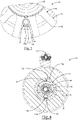
- a conduit may be formed through any area of the lamination stack 46 depending on design parameters of the system including, but not limited to, adjacent an opening 50 between the lamination stack teeth 48 on opposing ends, a variation of which is illustrated in phantom in FIG. 5 , or at an end portion 120 of a lamination stack tooth 48 on opposing ends, a variation of which is also illustrated in phantom in FIG. 5 .
- a conduit 108, 110 may be inserted into a tooth bore 130 created through the tooth 48 of the lamination stack 46.
- the retention fastener 102 may be attached to the conduit 108, 110 on a first side 132 of the tooth bore 130 to lock the retention device 184, 194 in place as shown in similar variations illustrated in FIG. 1 .
- the product 10 including any of its components (including the lubrication system 74, shaft 36, retention components 184, 194, compressor wheel 34, turbine wheel 32, housing 54, 56, or may be another component) may be made of aluminum, cast iron, molded plastic, carbon fiber, other die cast metal, or other suitable material.
- the components of the product 10 may be secured in the orientations illustrated by staking, casting it in position, machining, assembly, or other suitable means.
- a method which includes providing a turbomachinery device 10 comprising a rotational shaft 36, a first bearing 38, a second bearing 40 and an electric motor 42 comprising a stator 44 comprising a at least one retention component 184, 194 wherein the retention component 184, 194 is constructed and arranged to lock the stator 44 in an axial direction while locking rotation of the stator 44 about a rotational axis 16, wherein the retention component 184, 194 further comprises at least one conduit 84, 94 constructed and arranged to pass fluid 74 through the electric motor 42 to a second bearing 40, and wherein the at least one conduit 84, 94 includes at least one bore 85, 95 in a longitudinal side of the at least one conduit 84, 94.
- the method may further include feeding fluid 74 to one end of a housing 54, 56 so that fluid 74 is supplied to a first bearing 38 and through the at least one conduit 84, 94 so that fluid 74 is supplied to a second bearing 40.
- the retention component 184, 194 is constructed and arranged to prevent or substantially lessen an axial movement, a rotational movement, and optionally a radial movement of the stator 44 in relation to the shaft 36 or housing 54, 56.
- the retention component 184, 194 may be constructed and arranged to provide additional packing space within the product 10 due to its design and application.
- the retention component 184, 194 may be constructed and arranged to allow for avoidance of certain assembly and disassembly methods such as, but not limited to, press fits or shrink fits of the stator 44 into the housing 54, 56.
Landscapes
- Engineering & Computer Science (AREA)
- Mechanical Engineering (AREA)
- General Engineering & Computer Science (AREA)
- Power Engineering (AREA)
- Chemical & Material Sciences (AREA)
- Combustion & Propulsion (AREA)
- Structures Of Non-Positive Displacement Pumps (AREA)
- Supercharger (AREA)
Claims (20)
- Produit (10), comprenant :
un dispositif de turbo-machinerie (10) comprenant :un moteur électrique (42) entourant une partie d'un arbre (36), construit et agencé pour sélectivement entraîner l'arbre (36) en rotation autour d'un axe de rotation (16), dans lequel le moteur électrique (42) comprend en outre un stator (44) comprenant un empilement de feuilles (46) ;un carter (54, 56) entourant le moteur électrique (42), dans lequel le carter (54, 56) inclut une pluralité de canaux construits et agencés pour lubrifier un premier palier (38) ;caractérisé en ce que l'empilement de feuilles (46) inclut au moins un composant de retenue (184, 194), dans lequel le composant de retenue (184, 194) est construit et agencé pour bloquer le stator (44) dans une direction axiale tout en bloquant la rotation du stator (44) autour de l'axe de rotation (16), et dans lequel le composant de retenue (184, 194) comprend en outre au moins un conduit (84, 94) construit et agencé pour fournir un fluide, à travers le moteur électrique (42), à un second palier (40), eten ce que l'au moins un conduit (84, 94) inclut au moins un alésage (85, 95) dans un côté longitudinal de l'au moins un conduit (84, 94). - Produit selon la revendication 1, dans lequel l'empilement de feuilles (46) comprend en outre une pluralité de dents (48), et dans lequel l'au moins un conduit (84, 94) comprend une pluralité de conduits qui s'étendent chacun à travers des ouvertures (50) entre la pluralité de dents (48).
- Produit selon la revendication 1, dans lequel le composant de retenue (184, 194) comprend au moins une attache de retenue (106) construite et agencée pour fixer le stator (44) au carter (54, 56).
- Produit selon la revendication 3, dans lequel l'attache de composant de retenue (106) comprend un écrou attaché à une première extrémité (102) de l'au moins un conduit (84, 94) pour fournir une précharge pour le blocage du stator (44) dans un emplacement prédéterminé.
- Produit selon la revendication 4, dans lequel une seconde extrémité (104) de l'au moins un conduit (84, 94) atteint son point le plus bas dans la seconde partie de carter (46).
- Produit selon la revendication 4, dans lequel une première partie de carter (54) est glissée sur l'écrou pour former un dispositif d'étanchéité.
- Produit selon la revendication 1, comprenant en outre une roue de turbine de turbocompresseur (32) et dans lequel l'arbre (36) est fonctionnellement raccordé à la roue de turbine de turbocompresseur (32), et dans lequel la roue de turbine de turbocompresseur (32) entraîne l'arbre (36).
- Produit selon la revendication 1, comprenant en outre une roue de compresseur de turbocompresseur (34) et dans lequel l'arbre (36) est fonctionnement raccordé à la roue de compresseur de turbocompresseur (34) pour entraîner la roue de compresseur de turbocompresseur (34).
- Produit selon la revendication 1, comprenant en outre une première partie de carter (54) construite et agencée pour loger le premier palier (38) et ayant une première pluralité de canaux de fluide (76, 78, 80, 82, 92) ; une seconde partie de carter (56) construite et agencée pour loger le second palier (40) et ayant une seconde pluralité de canaux de fluide (88, 98) ; un tube d'alimentation en fluide (60) attaché à la première partie de carter (54), et dans lequel la première pluralité de canaux de fluide (76, 78, 80, 82, 92) et la seconde pluralité de canaux de fluide (88, 98) sont raccordées de façon fluidique à l'au moins un conduit (84, 94).
- Produit selon la revendication 9, dans lequel la première partie de carter (54) inclut en outre un alésage fileté (58) défini par une surface filetée intérieure et dans lequel le tube d'alimentation en fluide (60) est au moins partiellement fileté et est vissé dans l'alésage fileté (58).
- Produit selon la revendication 10, dans lequel le tube d'alimentation en fluide (60) inclut un dispositif pilote pour empêcher l'arrachement de filetage entre l'alésage fileté (58) et le tube d'alimentation en fluide (60).
- Produit selon la revendication 1, dans lequel l'au moins un conduit (84, 94) est d'une première longueur et le stator (44) est d'une seconde longueur, et dans lequel la première longueur de l'au moins un conduit (84, 94) est supérieure à la seconde longueur du stator (44).
- Produit selon la revendication 1, dans lequel l'au moins un conduit (84, 94) comprend au moins un trou débouchant dans l'empilement de feuilles (46) défini par une surface cylindrique intérieure.
- Produit selon la revendication 13, dans lequel l'au moins un conduit s'étend à travers une dent (48) de l'empilement de feuilles (46).
- Procédé, comprenant : la fourniture d'un dispositif de turbo-machinerie (10) comprenant un arbre rotatif (36), un premier palier (38), un second palier (40) et un moteur électrique (42) comprenant un stator (44) comprenant au moins un composant de retenue (184, 194), dans lequel le composant de retenue (184, 194) est construit et agencé pour bloquer le stator (44) dans une direction axiale tout en bloquant la rotation du stator (44) autour d'un axe de rotation (16), et dans lequel le composant de retenue (184, 194) comprend en outre au moins un conduit (84, 94) construit et agencé pour fournir un fluide, à travers le moteur électrique (42), à un second palier (409) ; et
l'alimentation en un fluide (74) à une extrémité d'un carter (54, 56) pour que le fluide soit fourni à un premier palier (38) et à travers l'au moins un conduit (84, 94) pour que le fluide soit fourni à un second palier (40), dans lequel l'au moins un conduit (84, 94) inclut au moins un alésage (85, 95) dans un côté longitudinal de l'au moins un conduit (84, 94). - Procédé selon la revendication 15, comprenant en outre la mise en rotation de l'arbre (36) autour de l'axe de rotation (16) tout en bloquant le stator (44) en place, dans la direction axiale et autour de l'axe de rotation, avec le composant de retenue (184, 194).
- Procédé selon la revendication 15, dans lequel le composant de retenue comprend au moins une attache de retenue (106) construite et agencée pour fixer le stator (44) au carter (54, 56).
- Procédé selon la revendication 17, dans lequel une première extrémité (102) du conduit (84, 94) est filetée pour accepter l'au moins une attache de retenue (106).
- Procédé selon la revendication 17, dans lequel l'au moins un conduit (84, 94) s'étend à travers une dent du stator (44).
- Procédé selon la revendication 15, dans lequel l'au moins un conduit (84, 94) est d'une première longueur et le stator (44) est d'une seconde longueur, et dans lequel la première longueur de l'au moins un conduit (84, 94) est supérieure à la seconde longueur du stator (44).
Applications Claiming Priority (1)
| Application Number | Priority Date | Filing Date | Title |
|---|---|---|---|
| PCT/US2016/031251 WO2017192149A1 (fr) | 2016-05-06 | 2016-05-06 | Composant de rétention pour dispositif de turbomachines |
Publications (3)
| Publication Number | Publication Date |
|---|---|
| EP3452708A1 EP3452708A1 (fr) | 2019-03-13 |
| EP3452708A4 EP3452708A4 (fr) | 2019-12-11 |
| EP3452708B1 true EP3452708B1 (fr) | 2022-06-22 |
Family
ID=60203179
Family Applications (1)
| Application Number | Title | Priority Date | Filing Date |
|---|---|---|---|
| EP16901146.7A Active EP3452708B1 (fr) | 2016-05-06 | 2016-05-06 | Composant de rétention pour dispositif de turbomachines |
Country Status (3)
| Country | Link |
|---|---|
| US (1) | US10502222B2 (fr) |
| EP (1) | EP3452708B1 (fr) |
| WO (1) | WO2017192149A1 (fr) |
Family Cites Families (15)
| Publication number | Priority date | Publication date | Assignee | Title |
|---|---|---|---|---|
| US2381122A (en) * | 1944-04-27 | 1945-08-07 | Carl J Fechheimer | Cooling means for dynamoelectric machines |
| DE1959280A1 (de) * | 1969-11-26 | 1971-06-03 | Blocher Motor Kg | Gleichstrommotor mit Hohllaeufer |
| US4241269A (en) * | 1978-06-28 | 1980-12-23 | Antonov Jury F | Directly liquid cooled rotor for electrical machine |
| US4577128A (en) | 1980-12-11 | 1986-03-18 | Northern Engineering Industries, Plc | Induction motors |
| US4514652A (en) | 1983-07-13 | 1985-04-30 | Sundstrand Corporation | Liquid cooled high speed synchronous machine |
| US5034638A (en) * | 1990-03-14 | 1991-07-23 | Westinghouse Electric Corp. | Generator auxiliary mode lubrication system and method |
| US5605045A (en) * | 1995-09-18 | 1997-02-25 | Turbodyne Systems, Inc. | Turbocharging system with integral assisting electric motor and cooling system therefor |
| US8820286B2 (en) * | 2003-08-28 | 2014-09-02 | Mainstream Engineering Corporation | Lightweight portable electric generator with integrated starter/alternator |
| JP4372511B2 (ja) * | 2003-10-17 | 2009-11-25 | トヨタ自動車株式会社 | 軸受間に延在する筒部材を有する回転電機付き過給機 |
| JP2006090274A (ja) | 2004-09-27 | 2006-04-06 | Toyota Motor Corp | 電動機付ターボチャージャ |
| CN102269056B (zh) | 2006-06-26 | 2013-10-23 | 福博科技术公司 | 无级变速器 |
| US8344576B2 (en) | 2009-06-03 | 2013-01-01 | EcoMotors International | Electric motor rotor |
| WO2011163226A2 (fr) * | 2010-06-21 | 2011-12-29 | Nidec Motor Corporation | Ensembles moteurs électriques comprenant un refroidissement de stator et/ou de rotor |
| US10119459B2 (en) * | 2015-10-20 | 2018-11-06 | Borgwarner Inc. | Oil supply conduit through stator lamination stack for electrified turbocharger |
| US9970450B1 (en) * | 2017-01-26 | 2018-05-15 | Borgwarner Inc. | Vented bearing retainer for turbomachines |
-
2016
- 2016-05-06 WO PCT/US2016/031251 patent/WO2017192149A1/fr not_active Ceased
- 2016-05-06 EP EP16901146.7A patent/EP3452708B1/fr active Active
- 2016-05-06 US US16/099,348 patent/US10502222B2/en active Active
Also Published As
| Publication number | Publication date |
|---|---|
| WO2017192149A1 (fr) | 2017-11-09 |
| US20190154049A1 (en) | 2019-05-23 |
| EP3452708A4 (fr) | 2019-12-11 |
| EP3452708A1 (fr) | 2019-03-13 |
| US10502222B2 (en) | 2019-12-10 |
Similar Documents
| Publication | Publication Date | Title |
|---|---|---|
| US6204577B1 (en) | Method and apparatus for space-saving installation of a starter-alternator | |
| EP3755907B1 (fr) | Pompe à liquide de refroidissement pourvue d'un dispositif palier optimisé et à bilan thermique amélioré | |
| US8096043B2 (en) | Method of assembling a pump motor and preloading bearings of the motor | |
| US20200295628A1 (en) | Electric Machine Having A Cooling Device | |
| US9356492B2 (en) | Electric machine with liquid cooled housing | |
| US6373155B1 (en) | Propulsion unit of vehicle | |
| US20140219777A1 (en) | Turbocharger | |
| KR101644287B1 (ko) | 과급기의 제조방법 및 과급기 | |
| US20140354090A1 (en) | Electric machine with liquid cooled housing and end cap | |
| DE112019000673T5 (de) | Schmier- und kühlsystem für eine elektrische maschine, elektrische maschine, die an einen turbolader gekoppelt ist, und entsprechender turbolader | |
| US20180278117A1 (en) | Electric motor | |
| EP2977615A1 (fr) | Pompe electrique | |
| KR20110134388A (ko) | 전기 기계용 액체 냉각 장치 | |
| KR102792937B1 (ko) | 전기 기계 조립체 및 회전자를 고정자에 록킹하기 위한 방법 | |
| US9641040B2 (en) | Rotating electric machine | |
| EP3358195A1 (fr) | Compresseur centrifuge | |
| JP2009284718A (ja) | 回転電機のコイルエンド冷却装置および冷却方法 | |
| CN111828822A (zh) | 车辆用电动机的轴承的润滑机构 | |
| EP3159507B1 (fr) | Conduit d'alimentation en huile à travers un empilement stratifié de stator pour turbocompresseur électrifié | |
| US4824324A (en) | Water pump | |
| EP3452708B1 (fr) | Composant de rétention pour dispositif de turbomachines | |
| WO2017207210A1 (fr) | Refroidissement d'une machine électrique | |
| US9611858B2 (en) | Water pump with reinforcement rib | |
| US7759838B2 (en) | Coil support for rotating electrical machine | |
| US20180328371A1 (en) | Backplate and method of making and using the same |
Legal Events
| Date | Code | Title | Description |
|---|---|---|---|
| STAA | Information on the status of an ep patent application or granted ep patent |
Free format text: STATUS: THE INTERNATIONAL PUBLICATION HAS BEEN MADE |
|
| PUAI | Public reference made under article 153(3) epc to a published international application that has entered the european phase |
Free format text: ORIGINAL CODE: 0009012 |
|
| STAA | Information on the status of an ep patent application or granted ep patent |
Free format text: STATUS: REQUEST FOR EXAMINATION WAS MADE |
|
| 17P | Request for examination filed |
Effective date: 20181205 |
|
| AK | Designated contracting states |
Kind code of ref document: A1 Designated state(s): AL AT BE BG CH CY CZ DE DK EE ES FI FR GB GR HR HU IE IS IT LI LT LU LV MC MK MT NL NO PL PT RO RS SE SI SK SM TR |
|
| AX | Request for extension of the european patent |
Extension state: BA ME |
|
| DAV | Request for validation of the european patent (deleted) | ||
| DAX | Request for extension of the european patent (deleted) | ||
| A4 | Supplementary search report drawn up and despatched |
Effective date: 20191107 |
|
| RIC1 | Information provided on ipc code assigned before grant |
Ipc: F02B 33/40 20060101ALI20191101BHEP Ipc: F04D 29/056 20060101ALI20191101BHEP Ipc: H02K 5/16 20060101ALI20191101BHEP Ipc: F02B 39/10 20060101AFI20191101BHEP Ipc: F04D 29/40 20060101ALI20191101BHEP Ipc: H02K 9/19 20060101ALI20191101BHEP Ipc: F02B 39/14 20060101ALI20191101BHEP Ipc: F04D 29/063 20060101ALI20191101BHEP Ipc: F04D 25/06 20060101ALI20191101BHEP |
|
| REG | Reference to a national code |
Ref country code: DE Ref legal event code: R079 Ref document number: 602016073080 Country of ref document: DE Free format text: PREVIOUS MAIN CLASS: F02B0039100000 Ipc: F04D0025060000 |
|
| GRAP | Despatch of communication of intention to grant a patent |
Free format text: ORIGINAL CODE: EPIDOSNIGR1 |
|
| STAA | Information on the status of an ep patent application or granted ep patent |
Free format text: STATUS: GRANT OF PATENT IS INTENDED |
|
| RIC1 | Information provided on ipc code assigned before grant |
Ipc: H02K 9/19 20060101ALI20210917BHEP Ipc: H02K 5/16 20060101ALI20210917BHEP Ipc: F02B 39/14 20060101ALI20210917BHEP Ipc: F02B 39/10 20060101ALI20210917BHEP Ipc: F02B 33/40 20060101ALI20210917BHEP Ipc: F04D 29/056 20060101ALI20210917BHEP Ipc: F04D 29/063 20060101ALI20210917BHEP Ipc: F04D 25/06 20060101AFI20210917BHEP |
|
| INTG | Intention to grant announced |
Effective date: 20211022 |
|
| GRAJ | Information related to disapproval of communication of intention to grant by the applicant or resumption of examination proceedings by the epo deleted |
Free format text: ORIGINAL CODE: EPIDOSDIGR1 |
|
| STAA | Information on the status of an ep patent application or granted ep patent |
Free format text: STATUS: REQUEST FOR EXAMINATION WAS MADE |
|
| GRAS | Grant fee paid |
Free format text: ORIGINAL CODE: EPIDOSNIGR3 |
|
| STAA | Information on the status of an ep patent application or granted ep patent |
Free format text: STATUS: GRANT OF PATENT IS INTENDED |
|
| GRAP | Despatch of communication of intention to grant a patent |
Free format text: ORIGINAL CODE: EPIDOSNIGR1 |
|
| INTC | Intention to grant announced (deleted) | ||
| INTG | Intention to grant announced |
Effective date: 20220307 |
|
| GRAA | (expected) grant |
Free format text: ORIGINAL CODE: 0009210 |
|
| STAA | Information on the status of an ep patent application or granted ep patent |
Free format text: STATUS: THE PATENT HAS BEEN GRANTED |
|
| AK | Designated contracting states |
Kind code of ref document: B1 Designated state(s): AL AT BE BG CH CY CZ DE DK EE ES FI FR GB GR HR HU IE IS IT LI LT LU LV MC MK MT NL NO PL PT RO RS SE SI SK SM TR |
|
| REG | Reference to a national code |
Ref country code: GB Ref legal event code: FG4D |
|
| REG | Reference to a national code |
Ref country code: CH Ref legal event code: EP |
|
| REG | Reference to a national code |
Ref country code: DE Ref legal event code: R096 Ref document number: 602016073080 Country of ref document: DE |
|
| REG | Reference to a national code |
Ref country code: AT Ref legal event code: REF Ref document number: 1499939 Country of ref document: AT Kind code of ref document: T Effective date: 20220715 |
|
| REG | Reference to a national code |
Ref country code: IE Ref legal event code: FG4D |
|
| REG | Reference to a national code |
Ref country code: LT Ref legal event code: MG9D |
|
| REG | Reference to a national code |
Ref country code: NL Ref legal event code: MP Effective date: 20220622 |
|
| PG25 | Lapsed in a contracting state [announced via postgrant information from national office to epo] |
Ref country code: SE Free format text: LAPSE BECAUSE OF FAILURE TO SUBMIT A TRANSLATION OF THE DESCRIPTION OR TO PAY THE FEE WITHIN THE PRESCRIBED TIME-LIMIT Effective date: 20220622 Ref country code: NO Free format text: LAPSE BECAUSE OF FAILURE TO SUBMIT A TRANSLATION OF THE DESCRIPTION OR TO PAY THE FEE WITHIN THE PRESCRIBED TIME-LIMIT Effective date: 20220922 Ref country code: LT Free format text: LAPSE BECAUSE OF FAILURE TO SUBMIT A TRANSLATION OF THE DESCRIPTION OR TO PAY THE FEE WITHIN THE PRESCRIBED TIME-LIMIT Effective date: 20220622 Ref country code: HR Free format text: LAPSE BECAUSE OF FAILURE TO SUBMIT A TRANSLATION OF THE DESCRIPTION OR TO PAY THE FEE WITHIN THE PRESCRIBED TIME-LIMIT Effective date: 20220622 Ref country code: GR Free format text: LAPSE BECAUSE OF FAILURE TO SUBMIT A TRANSLATION OF THE DESCRIPTION OR TO PAY THE FEE WITHIN THE PRESCRIBED TIME-LIMIT Effective date: 20220923 Ref country code: FI Free format text: LAPSE BECAUSE OF FAILURE TO SUBMIT A TRANSLATION OF THE DESCRIPTION OR TO PAY THE FEE WITHIN THE PRESCRIBED TIME-LIMIT Effective date: 20220622 Ref country code: BG Free format text: LAPSE BECAUSE OF FAILURE TO SUBMIT A TRANSLATION OF THE DESCRIPTION OR TO PAY THE FEE WITHIN THE PRESCRIBED TIME-LIMIT Effective date: 20220922 |
|
| REG | Reference to a national code |
Ref country code: AT Ref legal event code: MK05 Ref document number: 1499939 Country of ref document: AT Kind code of ref document: T Effective date: 20220622 |
|
| PG25 | Lapsed in a contracting state [announced via postgrant information from national office to epo] |
Ref country code: RS Free format text: LAPSE BECAUSE OF FAILURE TO SUBMIT A TRANSLATION OF THE DESCRIPTION OR TO PAY THE FEE WITHIN THE PRESCRIBED TIME-LIMIT Effective date: 20220622 Ref country code: LV Free format text: LAPSE BECAUSE OF FAILURE TO SUBMIT A TRANSLATION OF THE DESCRIPTION OR TO PAY THE FEE WITHIN THE PRESCRIBED TIME-LIMIT Effective date: 20220622 |
|
| PG25 | Lapsed in a contracting state [announced via postgrant information from national office to epo] |
Ref country code: NL Free format text: LAPSE BECAUSE OF FAILURE TO SUBMIT A TRANSLATION OF THE DESCRIPTION OR TO PAY THE FEE WITHIN THE PRESCRIBED TIME-LIMIT Effective date: 20220622 |
|
| PG25 | Lapsed in a contracting state [announced via postgrant information from national office to epo] |
Ref country code: SM Free format text: LAPSE BECAUSE OF FAILURE TO SUBMIT A TRANSLATION OF THE DESCRIPTION OR TO PAY THE FEE WITHIN THE PRESCRIBED TIME-LIMIT Effective date: 20220622 Ref country code: SK Free format text: LAPSE BECAUSE OF FAILURE TO SUBMIT A TRANSLATION OF THE DESCRIPTION OR TO PAY THE FEE WITHIN THE PRESCRIBED TIME-LIMIT Effective date: 20220622 Ref country code: RO Free format text: LAPSE BECAUSE OF FAILURE TO SUBMIT A TRANSLATION OF THE DESCRIPTION OR TO PAY THE FEE WITHIN THE PRESCRIBED TIME-LIMIT Effective date: 20220622 Ref country code: PT Free format text: LAPSE BECAUSE OF FAILURE TO SUBMIT A TRANSLATION OF THE DESCRIPTION OR TO PAY THE FEE WITHIN THE PRESCRIBED TIME-LIMIT Effective date: 20221024 Ref country code: ES Free format text: LAPSE BECAUSE OF FAILURE TO SUBMIT A TRANSLATION OF THE DESCRIPTION OR TO PAY THE FEE WITHIN THE PRESCRIBED TIME-LIMIT Effective date: 20220622 Ref country code: EE Free format text: LAPSE BECAUSE OF FAILURE TO SUBMIT A TRANSLATION OF THE DESCRIPTION OR TO PAY THE FEE WITHIN THE PRESCRIBED TIME-LIMIT Effective date: 20220622 Ref country code: CZ Free format text: LAPSE BECAUSE OF FAILURE TO SUBMIT A TRANSLATION OF THE DESCRIPTION OR TO PAY THE FEE WITHIN THE PRESCRIBED TIME-LIMIT Effective date: 20220622 Ref country code: AT Free format text: LAPSE BECAUSE OF FAILURE TO SUBMIT A TRANSLATION OF THE DESCRIPTION OR TO PAY THE FEE WITHIN THE PRESCRIBED TIME-LIMIT Effective date: 20220622 |
|
| PG25 | Lapsed in a contracting state [announced via postgrant information from national office to epo] |
Ref country code: PL Free format text: LAPSE BECAUSE OF FAILURE TO SUBMIT A TRANSLATION OF THE DESCRIPTION OR TO PAY THE FEE WITHIN THE PRESCRIBED TIME-LIMIT Effective date: 20220622 Ref country code: IS Free format text: LAPSE BECAUSE OF FAILURE TO SUBMIT A TRANSLATION OF THE DESCRIPTION OR TO PAY THE FEE WITHIN THE PRESCRIBED TIME-LIMIT Effective date: 20221022 |
|
| REG | Reference to a national code |
Ref country code: DE Ref legal event code: R097 Ref document number: 602016073080 Country of ref document: DE |
|
| PG25 | Lapsed in a contracting state [announced via postgrant information from national office to epo] |
Ref country code: AL Free format text: LAPSE BECAUSE OF FAILURE TO SUBMIT A TRANSLATION OF THE DESCRIPTION OR TO PAY THE FEE WITHIN THE PRESCRIBED TIME-LIMIT Effective date: 20220622 |
|
| PG25 | Lapsed in a contracting state [announced via postgrant information from national office to epo] |
Ref country code: DK Free format text: LAPSE BECAUSE OF FAILURE TO SUBMIT A TRANSLATION OF THE DESCRIPTION OR TO PAY THE FEE WITHIN THE PRESCRIBED TIME-LIMIT Effective date: 20220622 |
|
| PLBE | No opposition filed within time limit |
Free format text: ORIGINAL CODE: 0009261 |
|
| STAA | Information on the status of an ep patent application or granted ep patent |
Free format text: STATUS: NO OPPOSITION FILED WITHIN TIME LIMIT |
|
| 26N | No opposition filed |
Effective date: 20230323 |
|
| P01 | Opt-out of the competence of the unified patent court (upc) registered |
Effective date: 20230327 |
|
| PG25 | Lapsed in a contracting state [announced via postgrant information from national office to epo] |
Ref country code: SI Free format text: LAPSE BECAUSE OF FAILURE TO SUBMIT A TRANSLATION OF THE DESCRIPTION OR TO PAY THE FEE WITHIN THE PRESCRIBED TIME-LIMIT Effective date: 20220622 |
|
| REG | Reference to a national code |
Ref country code: CH Ref legal event code: PL |
|
| PG25 | Lapsed in a contracting state [announced via postgrant information from national office to epo] |
Ref country code: MC Free format text: LAPSE BECAUSE OF FAILURE TO SUBMIT A TRANSLATION OF THE DESCRIPTION OR TO PAY THE FEE WITHIN THE PRESCRIBED TIME-LIMIT Effective date: 20220622 |
|
| GBPC | Gb: european patent ceased through non-payment of renewal fee |
Effective date: 20230506 |
|
| REG | Reference to a national code |
Ref country code: BE Ref legal event code: MM Effective date: 20230531 |
|
| PG25 | Lapsed in a contracting state [announced via postgrant information from national office to epo] |
Ref country code: MC Free format text: LAPSE BECAUSE OF FAILURE TO SUBMIT A TRANSLATION OF THE DESCRIPTION OR TO PAY THE FEE WITHIN THE PRESCRIBED TIME-LIMIT Effective date: 20220622 Ref country code: LU Free format text: LAPSE BECAUSE OF NON-PAYMENT OF DUE FEES Effective date: 20230506 Ref country code: LI Free format text: LAPSE BECAUSE OF NON-PAYMENT OF DUE FEES Effective date: 20230531 Ref country code: IT Free format text: LAPSE BECAUSE OF FAILURE TO SUBMIT A TRANSLATION OF THE DESCRIPTION OR TO PAY THE FEE WITHIN THE PRESCRIBED TIME-LIMIT Effective date: 20220622 Ref country code: CH Free format text: LAPSE BECAUSE OF NON-PAYMENT OF DUE FEES Effective date: 20230531 |
|
| REG | Reference to a national code |
Ref country code: IE Ref legal event code: MM4A |
|
| PG25 | Lapsed in a contracting state [announced via postgrant information from national office to epo] |
Ref country code: IE Free format text: LAPSE BECAUSE OF NON-PAYMENT OF DUE FEES Effective date: 20230506 |
|
| PG25 | Lapsed in a contracting state [announced via postgrant information from national office to epo] |
Ref country code: IE Free format text: LAPSE BECAUSE OF NON-PAYMENT OF DUE FEES Effective date: 20230506 Ref country code: GB Free format text: LAPSE BECAUSE OF NON-PAYMENT OF DUE FEES Effective date: 20230506 |
|
| PG25 | Lapsed in a contracting state [announced via postgrant information from national office to epo] |
Ref country code: FR Free format text: LAPSE BECAUSE OF NON-PAYMENT OF DUE FEES Effective date: 20230531 Ref country code: BE Free format text: LAPSE BECAUSE OF NON-PAYMENT OF DUE FEES Effective date: 20230531 |
|
| PG25 | Lapsed in a contracting state [announced via postgrant information from national office to epo] |
Ref country code: BG Free format text: LAPSE BECAUSE OF FAILURE TO SUBMIT A TRANSLATION OF THE DESCRIPTION OR TO PAY THE FEE WITHIN THE PRESCRIBED TIME-LIMIT Effective date: 20220622 |
|
| PG25 | Lapsed in a contracting state [announced via postgrant information from national office to epo] |
Ref country code: BG Free format text: LAPSE BECAUSE OF FAILURE TO SUBMIT A TRANSLATION OF THE DESCRIPTION OR TO PAY THE FEE WITHIN THE PRESCRIBED TIME-LIMIT Effective date: 20220622 |
|
| PGFP | Annual fee paid to national office [announced via postgrant information from national office to epo] |
Ref country code: DE Payment date: 20250409 Year of fee payment: 10 |
|
| PG25 | Lapsed in a contracting state [announced via postgrant information from national office to epo] |
Ref country code: CY Free format text: LAPSE BECAUSE OF FAILURE TO SUBMIT A TRANSLATION OF THE DESCRIPTION OR TO PAY THE FEE WITHIN THE PRESCRIBED TIME-LIMIT; INVALID AB INITIO Effective date: 20160506 |
|
| PG25 | Lapsed in a contracting state [announced via postgrant information from national office to epo] |
Ref country code: HU Free format text: LAPSE BECAUSE OF FAILURE TO SUBMIT A TRANSLATION OF THE DESCRIPTION OR TO PAY THE FEE WITHIN THE PRESCRIBED TIME-LIMIT; INVALID AB INITIO Effective date: 20160506 |
|
| PG25 | Lapsed in a contracting state [announced via postgrant information from national office to epo] |
Ref country code: TR Free format text: LAPSE BECAUSE OF FAILURE TO SUBMIT A TRANSLATION OF THE DESCRIPTION OR TO PAY THE FEE WITHIN THE PRESCRIBED TIME-LIMIT Effective date: 20220622 |