EP3453174B1 - Verfahren und system für decodiererseitige intra-modus ableitung zur blockbasierten videocodierung - Google Patents
Verfahren und system für decodiererseitige intra-modus ableitung zur blockbasierten videocodierung Download PDFInfo
- Publication number
- EP3453174B1 EP3453174B1 EP17724201.3A EP17724201A EP3453174B1 EP 3453174 B1 EP3453174 B1 EP 3453174B1 EP 17724201 A EP17724201 A EP 17724201A EP 3453174 B1 EP3453174 B1 EP 3453174B1
- Authority
- EP
- European Patent Office
- Prior art keywords
- modes
- mode
- candidate
- intra prediction
- intra
- Prior art date
- Legal status (The legal status is an assumption and is not a legal conclusion. Google has not performed a legal analysis and makes no representation as to the accuracy of the status listed.)
- Active
Links
Images











Classifications
-
- H—ELECTRICITY
- H04—ELECTRIC COMMUNICATION TECHNIQUE
- H04N—PICTORIAL COMMUNICATION, e.g. TELEVISION
- H04N19/00—Methods or arrangements for coding, decoding, compressing or decompressing digital video signals
- H04N19/10—Methods or arrangements for coding, decoding, compressing or decompressing digital video signals using adaptive coding
- H04N19/134—Methods or arrangements for coding, decoding, compressing or decompressing digital video signals using adaptive coding characterised by the element, parameter or criterion affecting or controlling the adaptive coding
- H04N19/154—Measured or subjectively estimated visual quality after decoding, e.g. measurement of distortion
-
- H—ELECTRICITY
- H04—ELECTRIC COMMUNICATION TECHNIQUE
- H04N—PICTORIAL COMMUNICATION, e.g. TELEVISION
- H04N19/00—Methods or arrangements for coding, decoding, compressing or decompressing digital video signals
- H04N19/10—Methods or arrangements for coding, decoding, compressing or decompressing digital video signals using adaptive coding
- H04N19/102—Methods or arrangements for coding, decoding, compressing or decompressing digital video signals using adaptive coding characterised by the element, parameter or selection affected or controlled by the adaptive coding
- H04N19/103—Selection of coding mode or of prediction mode
- H04N19/11—Selection of coding mode or of prediction mode among a plurality of spatial predictive coding modes
-
- H—ELECTRICITY
- H04—ELECTRIC COMMUNICATION TECHNIQUE
- H04N—PICTORIAL COMMUNICATION, e.g. TELEVISION
- H04N19/00—Methods or arrangements for coding, decoding, compressing or decompressing digital video signals
- H04N19/10—Methods or arrangements for coding, decoding, compressing or decompressing digital video signals using adaptive coding
- H04N19/134—Methods or arrangements for coding, decoding, compressing or decompressing digital video signals using adaptive coding characterised by the element, parameter or criterion affecting or controlling the adaptive coding
- H04N19/146—Data rate or code amount at the encoder output
- H04N19/147—Data rate or code amount at the encoder output according to rate distortion criteria
-
- H—ELECTRICITY
- H04—ELECTRIC COMMUNICATION TECHNIQUE
- H04N—PICTORIAL COMMUNICATION, e.g. TELEVISION
- H04N19/00—Methods or arrangements for coding, decoding, compressing or decompressing digital video signals
- H04N19/10—Methods or arrangements for coding, decoding, compressing or decompressing digital video signals using adaptive coding
- H04N19/169—Methods or arrangements for coding, decoding, compressing or decompressing digital video signals using adaptive coding characterised by the coding unit, i.e. the structural portion or semantic portion of the video signal being the object or the subject of the adaptive coding
- H04N19/17—Methods or arrangements for coding, decoding, compressing or decompressing digital video signals using adaptive coding characterised by the coding unit, i.e. the structural portion or semantic portion of the video signal being the object or the subject of the adaptive coding the unit being an image region, e.g. an object
- H04N19/176—Methods or arrangements for coding, decoding, compressing or decompressing digital video signals using adaptive coding characterised by the coding unit, i.e. the structural portion or semantic portion of the video signal being the object or the subject of the adaptive coding the unit being an image region, e.g. an object the region being a block, e.g. a macroblock
Definitions
- Video coding systems are widely used to compress digital video signals to reduce the storage need and/or transmission bandwidth of such signals.
- block-based hybrid video coding systems are the most widely used and deployed.
- block-based video coding systems include international video coding standards such as the MPEG1/2/4 part 2, H.264/MPEG-4 part 10 AVC, VC-1, and the latest video coding standard called High Efficiency Video Coding (HEVC), which was developed by JCT-VC (Joint Collaborative Team on Video Coding) of ITU-T/SG16/Q.6/VCEG and ISO/IEC/MPEG.
- JCT-VC Joint Collaborative Team on Video Coding
- JEM Joint Exploration Model
- JEM reference software was based on HEVC Test Model (HM) that was developed by JCT-VC for HEVC. Any additional proposed coding tools need to be integrated into the JEM software, and tested using JVET common test conditions (CTCs).
- HM HEVC Test Model
- CTCs JVET common test conditions
- intra prediction modes are determined using a template-based algorithm at both the encoder and decoder.
- a flag may be signaled to indicate the usage of DIMD. In case the DIMD mode is selected, no intra mode needs to be signaled. The DIMD is also useful for error concealment with the intra prediction method.
- a template based algorithm may reduce intra mode signaling overhead, while also enabling derivation of the intra mode at any block level.
- the DIMD methods may increase the granularity of angular intra prediction, increasing the number of angular intra directions and capturing the directional edges in natural video accurately.
- DIMD searching algorithms may reduce encoder or decoder searching complexity while ensuring the majority of the DIMD gain.
- the video comprises a plurality of frames, each frame comprising blocks of samples.
- a plurality of candidate intra coding modes are tested by determining a cost of using each respective candidate mode to predict samples in a template region adjacent to the current block. Based on the cost, a derived intra coding mode is selected from the plurality of candidate intra coding modes. The samples in the current block are predicted with intra prediction using the derived intra coding mode.
- the cost is a measure of distortion between the template region and a prediction of the template region using the respective candidate intra coding mode.
- determining the cost of a candidate intra coding mode is performed as follows.
- the respective candidate intra coding mode is used to generate a prediction of the template region from a set of reconstructed reference samples, and distortion is measured between the template region and the prediction of the template region.
- the template region may include reconstructed samples adjacent to the current block.
- a flag is signaled on a block-by-block basis indicating whether decoder-side intra mode derivation is used for the current block.
- the level at which the flag is signaled may be different for different embodiments.
- the candidate intra coding modes include candidate modes selected from among modes used for intra coding of blocks neighboring the current blocks (spatial neighboring blocks and/or temporal neighboring blocks). In some embodiments, the candidate intra coding modes further include modes within a predetermined range of at least one of the modes used for intra coding of neighboring blocks.
- At least some blocks in the video are predicted using a predetermined set of explicitly-signaled intra modes.
- the candidate intra modes used for DIMD prediction may have a finer granularity than the predetermined set of explicitly-signaled intra modes, such that there is a smaller angle between adjacent prediction directions used for DIMD prediction than for explicitly-signaled intra modes.
- determining the cost of using each of a plurality of candidate intra coding modes may be performed using a multi-stage search.
- the multi-stage includes an initial stage in which the cost is determined for each of an initial set of candidate modes. The modes in the initial set are separated by an initial interval. In at least one subsequent stage, a subsequent set of candidate modes is selected based on the candidate mode in the previous stage having the lowest cost. The modes in the subsequent set are separated by a subsequent interval smaller than the interval used in the previous stage.
- the selected derived mode is included in a list of most probable modes.
- An index may be coded in the bitstream identifying the selected derived mode from the list of most probable modes.
- prediction residuals for the samples in the current block are coded in the bitstream using a transform coefficient scanning order, and the transform coefficient scanning order is independent of the selected derived mode.
- the transform coefficient scanning order may be a predetermined scanning order or the transform coefficient scanning order may be based on intra modes of spatial neighbors of the current block.
- Video encoders and decoders configured to perform DIMD are also described.
- Systems and methods herein provide novel techniques for prediction of sample values. Such techniques can be used by both encoders and decoders. Prediction of a sample results in a sample value that, in an encoding method, can be subtracted from an original sample input value to determine a residual that is encoded in the bitstream. In a decoding method, a residual can be decoded from the bitstream and added to the predicted sample value to obtain a reconstructed sample that is identical to or approximates the original input pixel. Prediction methods as described herein thus improve the operation of video encoders and decoders by decreasing, in at least some implementations, the number of bits required to encode and decode video. Further benefits of exemplary prediction methods to the operation of video encoders and decoders are provided in the Detailed Description.
- modules that carry out (e.g., perform, execute, and the like) various functions that are described herein in connection with the respective modules.
- a module includes hardware (e.g., one or more processors, one or more microprocessors, one or more microcontrollers, one or more microchips, one or more application-specific integrated circuits (ASICs), one or more field programmable gate arrays (FPGAs), one or more memory devices) deemed suitable by those of skill in the relevant art for a given implementation.
- ASICs application-specific integrated circuits
- FPGAs field programmable gate arrays
- Each described module may also include instructions executable for carrying out the one or more functions described as being carried out by the respective module, and it is noted that those instructions could take the form of or include hardware (i.e., hardwired) instructions, firmware instructions, software instructions, and/or the like, and may be stored in any suitable non-transitory computer-readable medium or media, such as commonly referred to as RAM, ROM, etc.
- Embodiments disclosed herein like the HEVC and JEM software, are built upon a block-based hybrid video coding framework.
- FIG. 1 is a functional block diagram of a block-based hybrid video encoding system.
- the input video signal 102 is processed block by block.
- extended block sizes called a "coding unit” or CU
- a CU can be up to 64x64 pixels, and bigger block size up to 256x256 is allowed in JEM.
- a CU can be further partitioned into prediction units (PU), for which separate prediction methods are applied.
- PU prediction units
- Spatial prediction uses pixels from the already coded neighboring blocks in the same video picture/slice to predict the current video block.
- Temporal prediction (also referred to as “inter prediction” or “motion compensated prediction”) uses reconstructed pixels from the already coded video pictures to predict the current video block. Temporal prediction reduces temporal redundancy inherent in the video signal.
- Temporal prediction signal for a given video block is usually signaled by one or more motion vectors which indicate the amount and the direction of motion between the current block and its reference block. Also, if multiple reference pictures are supported (as is the case for the recent video coding standards such as H.264/AVC or HEVC), then for each video block, its reference picture index is sent additionally; and the reference index is used to identify from which reference picture in the reference picture store (164) the temporal prediction signal comes.
- the mode decision block (180) in the encoder chooses the best prediction mode, for example based on the rate-distortion optimization method.
- the prediction block is then subtracted from the current video block (116); and the prediction residual is de-correlated using transform (104) and quantized (106) to achieve the target bit-rate.
- the quantized residual coefficients are inverse quantized (110) and inverse transformed (112) to form the reconstructed residual, which is then added back to the prediction block (126) to form the reconstructed video block.
- Further in-loop filtering such as de-blocking filter and Adaptive Loop Filters may be applied (166) on the reconstructed video block before it is put in the reference picture store (164) and used to code future video blocks.
- coding mode inter or intra
- prediction mode information, motion information, and quantized residual coefficients are all sent to the entropy coding unit (108) to be further compressed and packed to form the bit-stream.
- FIG. 2 is a functional block diagram of a block-based video decoder.
- the video bit-stream 202 is first unpacked and entropy decoded at entropy decoding unit 208.
- the coding mode and prediction information are sent to either the spatial prediction unit 260 (if intra coded) or the temporal prediction unit 262 (if inter coded) to form the prediction block.
- the residual transform coefficients are sent to inverse quantization unit 210 and inverse transform unit 212 to reconstruct the residual block.
- the prediction block and the residual block are then added together at 226.
- the reconstructed block may further go through in-loop filtering before it is stored in reference picture store 264.
- the reconstructed video 220 is sent out to drive a display device, as well as used to predict future video blocks.
- HEVC incorporates several coding tools that improve the efficiency of intra prediction over preceding video coding standards. Those intra coding tools can more accurately model different directional texture as well as smooth regions with gradually changing sample values. Moreover, additional efforts were also made during the design to avoid the introduction of artificial edges with potential blocking artifacts by doing adaptive smoothing of reference samples and the boundary samples of the generated intra prediction for DC and directly horizontal and vertical directions.
- the coding structure utilized for intra coding of HEVC closely follows the overall structure of the codec. Specifically, one picture is split into a number of CUs which represent the basic quad-tree splitting regions that are used to conduct intra coding. Inside one CU, multiple non-overlapping prediction units (PUs) can be defined, each of which specifies a region with individual intra prediction mode.
- PUs non-overlapping prediction units
- one intra-coded CU may have two types of PU partitions, namely, PART_2Nx2N and PART_NxN.
- PART_2Nx2N indicates that all the samples in the CU are predicted by the same intra prediction mode
- PART NxN indicates that the CU is split into four equal size PUs each of which is predicted by its own intra prediction mode.
- a given PU can be further split into quad-tree of transform units (TUs), each of which is the basic operational unit of applying residual coding with a transform with the size of the TU.
- TUs quad-tree of transform units
- the prediction operations of all intra prediction modes in HEVC are defined on the TU basis to minimize the distance between predicted samples and reference samples used in prediction for improved efficiency of intra prediction.
- HEVC Due to the number of possible intra prediction modes, HEVC considers five Most Probable Modes (MPMs) when coding luma intra prediction modes.
- MPMs Most Probable Modes
- the first two are derived by detecting the intra prediction modes of the above and left neighboring blocks and the remaining three MPMs are defined as Planar, DC and vertical direction (26). Additionally, in cases where both above and left blocks have the same angular mode, two neighboring angular directions closest to that direction will also be included in the MPM list.
- Intra prediction modes For all intra prediction modes in HEVC, the same set of previously decoded boundary samples from above and to the left of the current TU (as shown in FIG. 3 ) are used for prediction. Directional prediction with 33 different angular orientations are defined for various TU sizes ranging from 4x4 to 32x32. In addition to angular directions, planar prediction (which assumes a gradual changing surface with horizontal and vertical slope derived from boundaries) and DC prediction (which assumes a flat surface) can also be used. Table 1 specifies the mode index and intra prediction modes associated with each mode index.
- FIG. 4 illustrates the existing intra prediction modes as defined in HEVC.
- the horizontal, vertical, planar and DC modes can be explicitly signaled in bitstream; additionally, chroma prediction mode can be indicated to be the same as luma prediction mode through DM mode.
- Reference sample smoothing In HEVC, reference samples used for intra prediction are sometimes filtered by a 3-tap smoothing filter [1, 2, 1]/4, depending on TU size and the directionality of intra prediction. For 32x32 TUs, all angular modes except for direct horizontal and vertical use filtered reference samples. For 16x16 TUs, the intra modes that do not use filtered reference samples are extended to four modes (9, 11, 25 and 27) closest to horizontal and vertical. For 8x8 and smaller TUs, only diagonal modes (2, 18 and 34) use filtered reference for prediction. Additionally, reference smoothing is also applied to planar mode when the TU size is 8x8 or larger.
- Boundary smoothing To remove the discontinuities along TU boundaries, for three intra modes (DC, horizontal and vertical), the boundary samples along the intra prediction block are replaced by filtered samples from a 2-tap smoothing filter [3, 1]/4. Specifically, the prediction samples in the first row and the first column are filtered when DC mode is applied. The first prediction column for direct vertical mode and the first prediction row for direct horizontal mode are filtered.
- Intra coding tools in JEM In general, the basic structure of HEVC intra coding remains unchanged in JEM with several modules associated with intra predictions being further extended and/or improved, including extended intra prediction directions, 4-tap intra interpolation, extended boundary smoothing, position-dependent intra prediction combination, mode-dependent non-separable secondary transform and adaptive reference filtering. In the following, several intra coding tools in JEM are briefly reviewed.
- FIG. 5 illustrates the intra prediction modes as defined in JEM where the new directional modes over HEVC are highlighted as dotted lines and the Planar and DC modes remain the same.
- the extended directional intra prediction modes apply for all TU sizes and both luma and chroma intra predictions.
- an improved intra mode coding method uses six MPMs.
- the intra modes of the left and above neighboring blocks are checked. Instead of using the intra modes from top and left neighboring blocks directly as in HEVC, the most frequently used intra mode along the top neighboring row and along the left neighboring column are computed, and then used as the left and above neighboring modes, respectively.
- the same rule used in HEVC is firstly applied to obtain 3 MPMs; then, the remaining 3 MPMs are defined as the 3 intra modes closest to (in terms of prediction direction) the angular modes which have already been included in the list of MPMs.
- Table 2 specifies the MPM derivation method currently used in JEM, where L and A specify the most frequently used intra prediction mode of the left and above neighboring blocks, respectively, and Max and Min specify the maximum and the minimum of the intra prediction modes of the left and the above neighboring blocks, respectively. Table 2. Derivation of 6 MPMs in JEM.
- a low-pass filter [1, 2, 1]/4 is used to smooth reference samples for some intra prediction modes.
- the number of the intra prediction modes to which smooth filtering is applied depends on the block size and prediction mode. Specifically, for 32 ⁇ 32 blocks, all angular modes except horizontal and vertical use a filtered reference; for 16 ⁇ 16 blocks, the modes not using a filtered reference are extended to the four modes (9, 11, 25, 27) closest to horizontal and vertical; for 8 ⁇ 8 blocks, only the diagonal modes (2, 18, 34) use a filtered reference. Smoothing is also applied where the planar mode is used, for block sizes 8 ⁇ 8 and larger.
- RASF reference sample adaptive filtering
- Data hiding is a technique mainly used for watermarking.
- this method is applied to hide the signs of the most significant coefficients of TU's coefficients groups (CGs) into the parity of absolute values of CG's coefficients, which is referred to as sign bits hiding (SBH).
- SBH sign bits hiding
- data hiding is used to hide the flag that indicates whether the reference filtering is enabled for a given TU into the transform coefficients of that TU.
- SBH which uses all the coefficient in a given TU
- RSAF only uses those transform coefficients located at odd positions within the TU to hide a value of the filtering flag.
- Position dependent intra prediction combination In HEVC, intra prediction is computed from either a nonfiltered or a filtered set of reference border pixels, depending on the predictor mode and block size.
- the position dependent intra prediction combination extends this method by employing weighted combinations of filtered references and prediction samples calculated from unfiltered references, where the weights depend on prediction mode and pixel position.
- r and s Based on the notation used to define the intra predictors as shown in FIG. 6 , r and s represent the unfiltered and filtered reference samples, respectively.
- q [ x, y ] is the directional prediction derived from the filtered reference s as defined in HEVC but disabling boundary filters for DC, and direct horizontal and vertical intra directions.
- the values x and y are the horizontal and vertical distance from the block boundary.
- the filtered reference is derived by using binomial lowpass filters, since they can be easily adjusted for integer computations, and approximate Gaussian filters.
- the prediction parameters ( c 1 v , c 2 v , c 1 h , c 2 h ) and lowpass filter parameters are defined per prediction direction (neighboring prediction directions are grouped into 35 pairs) and block size. For each of 35 prediction direction pairs for a given block, 3 sets of prediction parameters and lowpass filters are predefined. The selected one from these 3 sets is signaled on the CU level.
- Mode-dependent non-separable secondary transform Due to the fact that the correlation between spatial neighboring samples is much less than that in temporal domain, there are usually strong correlation within the residual samples generated from intra prediction.
- mode-dependent non-separable secondary transform (NSST) is applied in the current JEM.
- NSST applies non-separable transforms to each 4x4 transform coefficient block of intra prediction.
- a CU-level index valued from 0 to 3 is explicitly signaled to identify which pre-defined secondary transform is applied. If the index is zero, secondary transform is not used; otherwise, one of the three pre-defined 4x4 non-separable transforms is used.
- the 4x4 non-separable transform identified by the CU-level index is applied. Additionally, the CU-level NSST flag is signaled only when there is at least one non-zero transform coefficient in the current CU.
- the 16x1 coefficient vector F ⁇ is subsequently re-organized as 4x4 block using the scanning order for that block (horizontal, vertical or diagonal).
- the scaling factor ⁇ is derived in the same way as the derivation of parameters ⁇ and ⁇ described above. The only difference is an addition of a regression cost relative to a default ⁇ value in the error function so that derived scaling factor is biased towards the default value (-0.5).
- intra prediction parameters are determined by the video encoder and explicitly transmitted in video bit-stream. Therefore, for intra-coded blocks, a significant amount of bit-rate is spent on the coding of the intra prediction parameters.
- the encoder In contrast to the video decoder, the encoder has access to the original video signal and therefore is able to quantify the distortion associated with the specific intra prediction parameter. This enables the encoder to optimize the intra prediction parameters such that the overall distortion is minimized at a given bit-rate constraint.
- This process of rate-distortion (R-D) optimization which typically involves the calculation of prediction distortion and signaling overhead of all possible intra prediction modes, is typically a computation intensive work. Due to the rapidly increasing computational resources in modern devices, even battery-powered devices are able to implement sophisticated algorithms at the decoder. For example, recent studies have shown that motion estimation at the decoder can provide significant coding gain. Since motion estimation is conducted at the decoder, transmission of motion vectors (MVs) can be omitted.
- MVs motion vectors
- DIMD decoder-side intra mode derivation
- DIMD may reduces the signaling overhead of the intra prediction mode. Instead of signaling the intra prediction mode explicitly, the mode is derived implicitly at the decoder side. If the derivation is accurate, no intra prediction direction information needs to be coded into bit-stream and compression efficiency is improved. However, the derived intra mode may not always be accurate enough. To avoid large prediction errors and to improve the coding performance, the DIMD mode may be adaptively selected at certain block level by performing an R-D optimization decision in a way similar to the Lagrangian optimization method which is used in HM and JEM.
- an additional flag derive_intra_prediction_mode flag may be used to transmit the encoder decision to the decoder, indicating whether the current block is predicted using an intra prediction mode derived from DIMD or using an intra prediction mode explicitly signaled in the bit-stream.
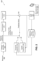
- FIG. 7 shows an exemplary diagram of a hybrid video encoder with a decoder-side intra mode derivation (DIMD) module 702.
- the encoder estimates the intra prediction mode by either conventional R-D based intra mode estimation methods (block 704) or the DIMD methods.
- the intra (or spatial) prediction module 706 generates the intra prediction signal by predicting the samples of the current block from its adjacent reconstructed samples belonging to neighboring block.
- the original signal is subtracted from the intra prediction signal (at 708) to remove spatial redundancy and produce the corresponding residual signal.
- the transform and quantization are applied to the residual signal which are then entropy-coded and output to the bit-stream.
- the reconstructed residual signal is made available by inverse quantization and inverse transform. Then, the reconstructed residual is added to the prediction signal.
- in-loop filtering processes e.g., de-blocking, ALF and SAO, are applied to the reconstructed video signal for output.
- a flag such as exemplary derive_intra_prediction_mode_flag may be signaled at a given block level (e.g., CU, PU, or TU level) to indicate whether the DIMD algorithm is applied to derive the intra prediction mode of the current block (e.g., indicating no need to transmit the intra prediction mode, reducing overhead).
- a given block level e.g., CU, PU, or TU level
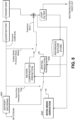
- FIG. 8 is an exemplary diagram of a hybrid video decoder with a DIMD module 802 that may receive a bit-stream produced by the exemplary encoder shown in FIG. 7 .
- the bit-stream may be first parsed by the entropy decoder 804.
- the residual coefficients are then inverse quantized and inverse transformed to obtain the reconstructed residual.
- the coding mode and prediction information are used to obtain the prediction signal using either spatial prediction or temporal prediction.
- the intra prediction mode is derived at the decoder by module 802; otherwise, the intra prediction mode is explicitly decoded from the bit-stream.
- a prediction signal is generated by module 806 by predicting the samples of the current block from its adjacent samples.
- the prediction signal and the reconstructed residual are then added together to get the reconstructed video.
- the reconstructed video may additionally go through loop filtering before being stored in the reference picture store to be displayed and/or to be used to decode future video signal.
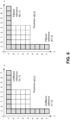
- FIG. 9 depicts an exemplary embodiment of the relationship between target samples, template samples and the reference samples of template used in an exemplary DIMD method.
- the target is denoted as the current block (of block size N) for which the intra prediction mode is to be estimated.
- the template (indicated by diagonally-hatched region in FIG. 9 ) specifies a set of already reconstructed samples that are used to derive the aforementioned intra prediction mode.
- the template size is denoted as the number of samples within L-shaped region that extends to the top and the left of the target block by distance L.
- the reference of the template (indicated by the cross-hatched region in FIG.
- DIMD may use the same set of reference samples as defined by HEVC intra prediction.
- the reference samples of template may not be reconstructed yet when encoding/decoding the target block.
- the reference samples substitution algorithm of HEVC may be utilized to substitute the unavailable reference samples with the neighboring available reference samples of the template.
- template size refers to the number of samples that the template region extends to the left and the top of the target block, the number represented by L in FIG. 9 .
- FIG. 9 shows the top and left template region to have the same size of extension, as indicated by the value L, in another embodiment of a DIMD method, different values of L, e.g. L1 and L2, may be used for the top and left template region.
- Choosing a large template size has the drawback that the samples of the template tend to be farther away from the target block. Therefore, the correlation between the template and the target block may be insufficient. Additionally, large template size also leads to increased encoding/decoding complexity, given that there are more template samples to be predicted during the DIMD process. On the other hand, large template size may also be advantageous in the sense that it can yield a more reliable estimation in the presence of noise (e.g., the video capture noise and the noise caused by the coding process). Therefore, it is beneficial to select the optimal template region for different block sizes, which should be large enough to be robust against noise while not exceeding a reasonable size limit to ensure sufficient correlation between template and the target block and reasonable complexity.
- noise e.g., the video capture noise and the noise caused by the coding process
- DIMD intra prediction mode
- coding using the DIMD mode is expected to permit accurate intra prediction with smaller block sizes since the intra direction does not need to be signaled in the bitstream for each block.
- DIMD allows selection from among a greater number of different intra directions without incurring the overhead of signaling a greater number of directions.
- the smaller block sizes and finer granularity of intra prediction directions i.e. a smaller angle between adjacent prediction directions) permits capturing directional edges in natural video more efficiently.
- the template size may be adaptively selected based on analyzing the signal contained in the template. For example, initially a small template may be selected. Analysis is done to decide the noise level in the small template. If the noise level is high (e.g., above a threshold), then a larger template may be selected to perform DIMD.
- different template layout may also be applied to the DIMD method.
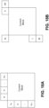
- FIGS. 10A-10D depict examples of different template layouts that may be applied for the DIMD method to estimate the intra prediction mode of the target block.
- the template layout may comprise: an L-shape template ( FIG. 10A ); a template using above neighboring samples ( FIG. 10B ); a template using left neighboring samples ( FIG. 10C ); and/or a template using both above and left neighboring samples ( FIG. 10D ).
- a DIMD method includes calculation for each intra prediction mode of the cost measured between the reconstructed template signal and the prediction signal obtained from the reference samples of the template.
- the template cost may be measured as the distortion between the two. Similar to other block-based matching schemes, different template cost measurements may be applied by the DIMD method, such as sum of absolute difference (SAD), sum of square difference (SSD) and sum of absolute transformed difference (SATD).
- SAD sum of absolute difference
- SSD sum of square difference
- SATD sum of absolute transformed difference
- the cost may also be measured as the sum of small sub-block unit (e.g., 2x2 or 4x4) contained in the template.
- the intra prediction mode that yields the minimum template cost will be selected as the optimal DIMD intra prediction mode of the target block.
- the optimal DIMD mode is then compared with the optimal mode from normal intra prediction (with explicitly signaled prediction mode), for example, using rate distortion optimization criterion or another criterion of the encoder's choice. If there is strong correlation between the target block and its template, the optimal DIMD mode is likely to provide a good estimate of the intra prediction mode of the adjacent target block.
- the intra mode derived by DIMD is used not only to improve the efficiency of intra coding by saving the overhead of signaling intra modes but also (or alternatively) to enhance the error concealment of the coding blocks coded with intra mode.
- the proposed DIMD method may be applied to provide an estimate of the original intra mode and ensure acceptable reconstruction quality of the intra-coded blocks for clients.
- the number of the angular intra modes is 65.
- the number of 65 is selected in order to provide an increased intra prediction granularity without overwhelmingly increasing the signaling overhead of intra prediction mode which may neutralize the coding gain obtained from the increased intra prediction accuracy.
- the intra prediction mode is estimated at the decoder for the DIMD method, no intra prediction information needs to be coded into bit-stream. Therefore, when the DIMD mode is enabled, the number of directional intra prediction modes can be increased with no signaling cost.
- the granularity of angular intra prediction modes is increased (but without increased signaling cost).
- bilinear interpolation is applied to obtain intra predicted samples when the target samples are predicted from one reference sample at fractional position. Specifically, each predicted sample P(x,y) at location (x,y) is obtained by projecting its location onto a reference row of pixels based on the selected prediction direction and interpolating a value for the sample at 1/32 sample accuracy, where bilinear interpolation is performed linearly utilizing two closest reference samples at integer position.
- p x y 32 ⁇ w y ⁇ R i + w y ⁇ R i + 1 + 16 ⁇ 5
- w y is the weighting parameter between two integer reference samples R i and R i +1 which specifies the segment covering the projected fractional location and » denotes a right bit-shift operation.
- Table 3 specifies the values of the projection displacement d for different intra prediction directions. Table 3 Mapping between intra prediction direction preModeIntra and projection displacement d for the 33 angular intra prediction directions in HEVC predModeIntra 1 2 3 4 5 6 7 8 9 10 11 12 13 14 15 16 17 d - 32 26 21 17 13 9 5 2 0 -2 -5 -9 -13 -17 -21 -26 predModeIntra 18 19 20 21 22 23 24 25 26 27 28 29 30 31 32 33 34 d -32 -26 -21 -17 -13 -9 -5 -2 0 2 5 9 13 17 21 26 32
- the accuracy of the intra interpolation filtering is increased when the DIMD mode is enabled for the current video block.
- 2 B the number of defined fractional samples for the finer granularity intra prediction
- the dynamic range of the projection displacement d may also be enlarged in order to represent the tangent values of the increased intra prediction granularity.
- Table 4 shows the projection displacement values d associated with the 129 angular intra prediction directions.
- a DIMD method with increased angular direction granularity may be used in combination with other interpolation methods.
- H is the number of bits for representing filter coefficients.
- the derived intra prediction mode may be used as one of the MPM candidates to predict the intra prediction modes of neighboring intra blocks.
- the high-accuracy intra prediction directions of the DIMD-coded blocks may be rounded to the intra prediction accuracy of normal intra mode in order to ensure the intra prediction mode of the neighboring intra blocks to be predicted and the MPM candidate from the DIMD mode have the same precision.
- the high-accuracy intra prediction mode of the current DIMD block may be rounded to the nearest intra prediction mode in the coarse granularity (e.g., 65 angular directions) before it is stored and used as MPM candidate for predicting the intra prediction mode of its neighboring intra blocks.
- the coarse granularity e.g. 65 angular directions
- one fixed rule e.g., always rounding to the coarse-accuracy intra direction with smaller intra direction index, or always rounding to the coarse-accuracy intra direction which is closer to 45 degrees
- one fixed rule e.g., always rounding to the coarse-accuracy intra direction with smaller intra direction index, or always rounding to the coarse-accuracy intra direction which is closer to 45 degrees
- the DIMD mode is enabled/disabled (as indicated by the flag derive_intra_prediction_mode_flag) at the CU level.
- the adaptation of the derived intra prediction mode can be conducted at various coding levels, such as CU level, PU level and TU level. Each adaptation level provides different trade-offs between coding efficiency and encoding/decoding complexity. For example, if the derived intra prediction mode is adapted at the TU level, the encoder/decoder derives an intra prediction mode for each individual TU.
- the encoder/decoder derives one intra prediction mode for each individual PU and all the TUs inside that PU will use the same derived intra mode for their own intra prediction. If the derived intra prediction mode is adapted at the CU level, encoder/decoder only derives one intra prediction mode for the whole CU, and all the TUs inside that CU will use the same derived intra mode for their intra prediction.
- the flag derive_intra_prediction_mode_flag may be only signaled when the CU only has one PU (e.g. 2Nx2N).
- the level to enable/disable the DIMD mode does not have to be the same as the adaptation level of deriving the intra prediction mode.
- the DIMD mode may be enabled at the CU level while the corresponding intra prediction mode derivation may be done at either CU level, PU level or TU level.
- the level to enable/disable the DIMD mode is kept to be the same as that of intra prediction mode derivation.
- the level to enable/disable the DIMD mode is different from the level of intra prediction mode derivation, and the level of intra prediction mode derivation can be lower than the level of DIMD mode signaling.
- each PU or TU in that CU can still apply the DIMD method to derive their own intra prediction mode separately.
- the CU level flag, derive_intra_prediction_mode_flag is turned on, that is, DIMD is enabled for the current CU, an additional flag may be signaled to indicate the level (e.g., PU level or TU level) at which DIMD is performed in the current CU.
- the level e.g., PU level or TU level
- RQT Recursive Quad Tree
- the PU When the RQT depth is equal to 0, the PU is not further split, and there is only one TU in the PU with the same size.
- the additional flag is not signaled, and DIMD is performed at PU level (which is the same as TU level).
- the PU When the RQT depth is larger than 0, the PU may be further split into more than one TU.
- the additional flag is signaled (after RQT depth is signaled), and its value may be used to determine the level at which DIMD is performed (TU or PU level) in the current CU.
- the intra prediction modes of DIMD-coded blocks are estimated at the decoder side.
- the searching method used to find the intra prediction mode that yields the best template distortion has a significant impact on the complexity and overall performance of the DIMD method, as the same searching process is performed at both the encoder and the decoder in order to ensure that the reconstructed video at the decoder matches that at the encoder.
- different searching methods are disclosed which can result in various trade-offs between coding performance and encoding/decoding complexity.
- Full search for DIMD One method of searching for the optimal intra prediction mode for DIMD is full search, where the template cost measurement (as discussed above) is calculated for all available intra prediction modes and the one having the minimal template cost will be selected as the intra prediction mode of the target block.
- the full search method can estimate the intra prediction mode in the most accurate way, it introduces a high amount of complexity increase (especially at the decoder) and therefore may not be preferable for practical codec design. This method is thus only included for illustration purposes and not covered by the claims.
- Multi-stage search for DIMD when the DIMD mode is selected, the number of supported directional intra prediction modes is sufficient to cover the edge directions in natural video, especially when the high-accuracy intra prediction (e.g. fine granularity intra prediction) is enabled for DIMD. Therefore, the template costs of those neighboring intra prediction modes may not deviate substantially. Therefore, in order to reduce the searching complexity, in one embodiment a multi-stage search method is used to identify the optimal intra prediction mode.
- Such multi-stage searching process compares at each stage the template cost measurement for a subset of intra prediction mode candidates within an initial searching interval and maintain the intra prediction mode that minimizes the cost; the selected intra prediction mode from the last stage will be used as the searching center for the current stage with a reduced searching interval (e.g., the search interval may be reduced by half).
- This multi-stage method is thus included in the appended claims. Specifically, the above searching method can be summarized by the following procedures:
- FIG. 11A is a flow chart of an exemplary DIMD multi-stage searching method as set forth above.
- a different number of candidates e.g., more than three candidates may be tested at each stage to select the optimal mode at that stage.
- the search starting point has an effect on the overall DIMD performance, which determines whether the whole searching process could converge to the actual intra direction of the local area.
- FIG. 11A only three intra modes (e.g., one center intra mode and two boundary intra modes) are served as the candidates to determine the starting search point at the initial stage, which may not be good enough to estimate the local intra prediction direction. Therefore, to further improve the DIMD performance while maintaining an acceptable encoding/decoding complexity, an initial estimation process is used in the disclosed multi-stage DIMD searching method to provide a better initial search point.
- a candidate list S init is firstly created by selecting N fixed modes from the allowed intra modes and then the template costs are measured for the candidate intra modes in S init and the one that minimizes the cost is selected as the starting search direction. Based on the starting direction determined by the above estimate process, the multi-stage searching process is then applied to find the best estimate of local intra direction through iteratively updating the searching center and the search interval in the same way as shown in FIG. 11A .
- this searching process can be described by the following procedures:
- FIG. 11B-11C is a flowchart of an exemplary embodiment of the DIMD multi-stage searching method using the disclosed improved estimation of the initial search direction.
- DC and Planar modes may, in some embodiments, always be included in the initial candidate list S init to determine the starting search mode.
- the multi-stage search process may be directly skipped in case the starting search mode is either DC or Planar.
- DC and Planar modes may be adaptively added into the initial candidate list based on the local characteristic of the current coding block (e.g., referring to the intra modes of neighboring blocks).
- DC and Planar modes may be considered as the candidates to find the optimal starting search mode (e.g., being included in the initial candidate list); otherwise, DC and Planar may not be considered (e.g., being excluded from the initial candidate list).
- different intra modes may be used to generate the initial candidate list for determining the optimal starting search intra mode.
- the default 35 intra modes as defined by HEVC e.g., 33 angular directions plus DC and Planar modes, may be used to form the initial candidate list for determining the initial search.
- other selection method of initial candidate intra modes may also be applied at the initial stage of the disclosed fast searching method.
- a number of angular intra modes are always included in the initial search candidate list S init . This may increase the complexity of the initial search process.
- the template costs of up to three candidate intra modes are calculated at each stage.
- the increased granularity of intra modes for the DIMD mode provides a more accurate description of the fine edges in natural video.
- the template cost of close neighboring intra modes may not deviate a lot, and therefore may not have a significant coding performance difference when they are used as the intra mode of DIMD block.
- an early termination method is proposed to simplify the complexity of the multi-stage search process. Specifically, at one given stage, the template costs of the N candidate intra modes, i.e., TC 0 , TC 1 , ..., TC N-1 , are calculated at the current stage.
- FIGS. 19A and 19B are a flowchart of one embodiment of the proposed multi-stage DIMD searching method with the early termination conditions on the intra modes of spatial neighbors and the variation of the template costs of the searching candidates at each stage.
- Candidate-based DIMD search To speed-up the DIMD searching process, in one embodiment, a candidate-based searching algorithm may be used.
- the principle of the candidate-based searching method is to select a set of unique intra prediction modes for which the template cost measurement needs to be calculated.
- the number of the intra prediction mode candidates in the set should be relatively small in order to significantly reduce the searching complexity of DIMD.
- several intra prediction mode candidates as discussed below may be evaluated due to their suitability. This method is included for illustration purposes only.
- the modes of the temporal neighbors may also be used. For example, if the collocated blocks in a neighboring picture are coded using intra prediction, then the prediction modes of those temporal neighboring blocks may be included in the candidate list as well.
- DIMD for chroma DIMD for chroma
- a video coding system usually devotes more bits to the luma component than chroma components, e.g., by adjusting the QP delta value between luma component and chroma components. Therefore, the chroma components contain much less detail information (e.g., edges and textures) than the luma component. Based on this observation, there is no need to check as many intra prediction modes for chroma DIMD as for luma DIMD. On the other hand, given the strong correlation between luma plane and chroma planes, it is highly possible that chroma prediction uses the same intra prediction mode as the luma prediction. Therefore, in one embodiment of the disclosure, when the DIMD mode is enabled for one video block, the chroma component will reuse the same intra prediction mode as that derived for the luma component.
- the linear model (LM) mode as specified in current JEM may also be considered when DIMD mode is enabled for the current block in order to improve the chroma coding efficiency and thus the overall R-D performance of the DIMD mode. Therefore, in one embodiment of the disclosure, when DIMD mode is enabled for one video block, both the derived intra prediction mode of luma component and the LM mode will be tested for the template samples; then, the one with smaller template cost will be selected as the intra prediction mode of the chroma components.
- the DIMD method can provide a good estimate of the optimal intra prediction mode for the target block.
- This estimated intra prediction mode can be used not only to avoid the signaling of intra prediction parameters (e.g., intra prediction modes) of the DIMD-coded blocks, but also to predict the intra prediction modes of non-DIMD-coded neighboring blocks due to the strong spatial correlation of natural video content.
- the derived intra prediction direction from DIMD may be added as one candidate into the MPM list for intra mode prediction of the current block which is coded by normal intra mode (that is, its intra prediction mode is explicitly signaled).
- the intra mode derived by DIMD may be added as one additional candidate of the MPM list and increase the size of the MPM list by 1.
- one embodiment of the method may replace one existing MPM candidate (e.g., the last MPM candidate) by the DIMD derived prediction mode and the size of the MPM list may be kept unchanged.
- one embodiment of the method may always place the DIMD derived prediction mode at the first place in the MPM list. Also, one embodiment may include a pruning operation such that the DIMD derived mode will not be added into the MPM list if it is redundant (i.e., if the DIMD derived mode is exactly the same as one existing MPM candidate in the list).
- Some embodiments combine the DIMD method with the existing intra coding tools of JEM.
- NST non-separable secondary transform
- PDPC position dependent intra prediction combination
- RAF reference sample adaptive filtering
- the CU-level NSST flag is signaled only when there is at least one non-zero transform coefficient in the current CU, e.g., rqt_root_cbf is equal to 1.
- the DIMD mode is applied below CU level, that is, at TU-level or PU-level, the corresponding parsing and decoding processes are carried over at the TU-level or PU-level, given the reconstructed samples of the current TU or PU may be used as the template for the samples of its neighboring TU or PU.
- one embodiment of the disclosure may postpone the signaling of NSST flag until the transform coefficients of the first non-all-zero TU in CU are signaled.
- the decoder always starts with setting the NSST flag as 0, and parse and decode the TUs in the CU according to the decoding order; after the decoder parses the transform coefficients of the first TU in the CU that has at least one non-zero coefficient, the decoder will continue to parse the NSST flag value from the bit-stream and use it for the decoding process of the current and the following TUs.
- Table 5 illustrates an embodiment of the NSST flag signaling when DIMD and NSST are jointly enabled. The location of the NSST flag is marked by *.
- the DIMD mode is enabled by deriving the intra prediction mode using template samples in the manner of HEVC intra prediction, where an intra prediction signal is computed from either a nonfiltered or a filtered set of reference border pixels, depending on the predictor mode and block size.
- an intra prediction signal is computed from either a nonfiltered or a filtered set of reference border pixels, depending on the predictor mode and block size.
- PDPC when PDPC is enabled, it generates the intra prediction signal by employing weighted combinations of filtered references and predictions from unfiltered references.
- the intra prediction mode derived in the HEVC intra prediction manner cannot provide a good estimate of the optimal intra prediction mode of one PDPC-coded block because PDPC is not considered in the intra prediction mode derivation process. Therefore, in order to improve the coding efficiency of DIMD, one embodiment of the disclosure may estimate the intra prediction mode of the target block by predicting template samples based on PDPC intra prediction when PDPC mode is enabled for the target block.
- the PDPC intra prediction (as specified in Equations (1) and (2)) is firstly applied to the reference samples of the template to generate the corresponding intra prediction signal of the template for each intra prediction mode (as shown FIG. 6 ). Then, the encoder/decoder will calculate the template cost measurements between the reconstructed template signal and each prediction signal of the template. The intra prediction mode that has the smallest cost will be considered as the intra prediction mode of the target block.
- the transform coefficient parsing process is dependent on the intra prediction mode of the TU (because the intra prediction mode is used to infer the scanning order of the transform coefficients), it is impossible to know which low-pass filter is selected (the RSAF flag) when deriving the intra prediction mode of the DIMD-coded TUs.
- one embodiment of the present disclosure may remove the parsing dependency of coefficient scanning order on intra prediction direction for DIMD-coded TUs.
- one fixed scanning order e.g., diagonal scan order
- the decoder is able to parse the transform coefficients of one DIMD-coded TU without knowing the specific intra prediction mode of the TU and therefore identify the value of the RSAF flag of the TU.
- the low-pass filter indication is inferred after all transform coefficients within TU are parsed.
- the corresponding low-pass filter (as indicated by the RSAF flag) will be used to derive the intra prediction mode based on the template which is then used to do the intra prediction of the current block.
- one fixed reference sample low-pass filter may be used for DIMD; this low-pass filter may be different from the low-pass filter indicated by the RSAF flag which is used for target block coding.
- mode dependent coefficient scanning is used to improve the efficiency of transform coefficient coding.
- the scanning order of certain block sizes (4x4 and 8x8 TUs in HEVC, and BTs which have either width or height smaller or equal to 8) is determined by the intra prediction mode.
- Each intra prediction mode can use one of three possible scanning orders: diagonal, horizontal and vertical.
- a look-up table is used to map each intra prediction mode into a corresponding scanning order. Based on this design, there are three issues that make the transform coefficient scanning order not be able to be directly derived during the parsing stage after the DIMD is introduced.
- the intra modes of DIMD coded blocks are derived from the reconstructed neighboring samples. Therefore, the scanning order of DIMD coded blocks can only be known after all the corresponding neighboring samples are fully reconstructed, e.g., at the decoding/reconstruction stage. This means that the transform coefficients of DIMD coded blocks cannot be parsed until all their top and left neighboring samples are fully reconstructed.
- both HEVC and JEM define a set of MPM candidates when coding intra prediction mode predictively.
- some are obtained from the intra prediction modes of the spatial neighbors of the current block.
- the scanning order of the current block can only be obtained after the neighboring block is fully reconstructed at the decoding/reconstruction stage. This means that the transform coefficients of normal intra blocks which refers to one or more DIMD blocks as MPM candidates cannot be parsed until the reference DIMD blocks are fully reconstructed.
- both HEVC and JEM allow selection of one of five modes: planar, DC, horizontal, vertical and DM (note that in addition to the five modes, JEM allows another cross-component linear mode (LM) where chroma components are predicted from the reconstructed luma component using a linear mode).
- the DM mode specifies that the chroma components use the same intra prediction mode of the luma component.
- angular intra mode 34) is used to replace the duplicated intra mode.
- chroma intra prediction mode depends on the intra prediction mode of the corresponding luma component.
- QTBT quadtree plus binary tree
- such luma-chroma intra mode parsing dependency can make chroma intra mode not be able to be derived during the parsing stage.
- the intra mode of the current chroma block is DM and the luma block that the chroma block refers to is coded by DIMD mode
- the actual intra mode of the chroma block can only be obtained after the neighboring samples of the corresponding DIMD luma block are full reconstructed.
- truncated binary code (TBC) is used to code the NSST index, for which the number of transform candidates (e.g., the size of the transform set) needs to be known for binarization. Therefore, it can be seen that the NSST index cannot be parsed without knowing whether the intra mode of the current block is angular or not. In a case where the current block is coded by DIMD, such information cannot be obtained until the neighboring samples of the current block is reconstructed (e.g., at the decoding/reconstruction stage).
- Parsing dependency related with RSAF Parsing dependency related with RSAF.
- adaptive reference filtering is only applied to intra blocks which are not coded by DC mode. Therefore, the decision whether the reference filtering is applied to the current block (which is done during the transform coefficient parsing stage through data hiding) is dependent on the intra mode of the current block. In a case where the current block is coded by DIMD, such information cannot be obtained before the decoding/reconstruction process.
- the intra mode derived by DIMD can also be used as an MPM candidate for predicting the intra mode of the spatial neighbors of the current block; also, when different QTBT (of which one exemplary embodiment is illustrated in FIG. 16 ) structures are used to code luma and chroma components separately, the DIMD intra mode derived for the luma component can also be referred to determine the scanning order of chroma transform coefficients when the chroma block selects DM mode. Therefore, in order to remove those parsing dependencies, the fixed intra mode is not only used for the parsing the transform coefficients of DIMD coded blocks but also used for the MPM-based intra mode prediction and chroma DM mode.
- FIGS. 17A and 17B illustrate two examples of using the intra modes of DIMD coded blocks (highlighted by shadow blocks) for MPM-based intra mode prediction and chroma DM mode, respectively, by assuming planar mode is always used for DIMD coded blocks.
- a fixed intra mode is always used for each DIMD coded block at the parsing stage.
- the selected intra mode is not only used for scanning the transform coefficients of the block but also used as MPM candidate for predicting the intra modes of its spatial neighbors. In case the selected intra mode significantly deviates from the actual intra mode of the DIMD block, this may severely reduce the efficiency of intra mode prediction for its neighboring blocks and therefore lower the overall coding efficiency.
- an intra mode propagation method is disclosed to propagate the intra modes of normal intra blocks (e.g., explicitly signaled intra modes) into the DIMD blocks.
- this embodiment derives the intra mode of each DIMD block that is used to determine the coefficient scanning order at the parsing stage from the intra modes of its spatial neighbors, such that the decoder is capable of parsing the transform coefficients without access to the decoded intra mode of the DIMD block. Additionally, due to the strong correlation between the intra modes of spatial neighboring blocks, this embodiment can usually provide a good estimate of the decoded intra mode of DIMD block, therefore minimize the coding efficiency loss incurred from transform coefficients scanning. Additionally, given that the propagated intra mode can be used as MPM candidate to predict the intra mode of neighboring normal intra blocks, this method may enhance the correlation between intra modes of spatial adj acent blocks, which may be beneficial to improve the signaling efficiency of explicit intra mode.
- Different sets of spatial neighbors may be used in the intra mode propagation method to derive the intra mode of each DIMD coded block.
- the set of the spatial neighbors consists of the blocks at the top neighboring row and the left neighboring column of the current DIMD block; and the intra mode that is most frequently used among the spatial neighbors is selected as the propagated intra mode of the DIMD block.
- the five spatial neighbor candidates as defined in the merge mode e.g., left (L), above (A), below-left (BL), above-right (AR) and above-left (AL), are used; and the intra mode that is most frequently used among the five spatial neighbors is selected as the propagated intra mode the DIMD block.
- FIGS. 18A and 18B illustrate the positions of the spatial neighbors used by the intra mode propagation method. Additionally, in each of the above two spatial neighbor selection methods, if any candidate neighboring block is not intra-coded or outside the current slice/tile, it is considered as unavailable. In another embodiment, if any spatial neighbor is not intra-coded or outside the current slice/tile, it is always considered as being coded by a fixed intra mode (e.g., planar).
- a fixed intra mode e.g., planar
- the fixed intra mode (as described in embodiment one) and the propagated intra mode (as described in embodiment two) are only used at the parsing stage.
- the intra mode of each DIMD coded block may be adjusted based on the template-based intra mode derivation method using the reconstructed samples of neighboring blocks, as described previously.
- Remove syntax parsing dependency of NSST and RSAF on decoded DIMD intra mode As disclosed above, different number of secondary transform candidates are defined for angular intra modes (4 transform candidates) and non-angular intra modes (3 transform candidates) in the current NSST design. And, as the TBC is used to code the NSST index, the number of available transform candidates may be specified for the binarization process. Additionally, the reference sample filtering is not enabled for DC mode. These designs could lead to syntax parsing dependency when being jointly applied with DIMD, as the intra mode of each DIMD block is not obtained until its neighboring samples are fully reconstructed.
- a method may assume DIMD blocks to be coded by a fixed intra mode (e.g., planar mode) when parsing the NSST and RSAF related syntax elements.
- a method may use the propagated intra mode (as described above) to parse the NSST and RSAF related syntax elements.
- a method may remove the syntax signaling conditions of NSST and RSAF on intra mode when one block is coded by the DIMD mode, such that the NSST and RSAF syntax elements can be parsed without knowing the corresponding intra mode.
- a method may always use 4 transform candidates or 3 transform candidates for DIMD coded blocks; additionally, a method may always enable or disable RSAF for DIMD coded blocks.
- Exemplary embodiments disclosed herein are implemented using one or more wired and/or wireless network nodes, such as a wireless transmit/receive unit (WTRU) or other network entity.
- WTRU wireless transmit/receive unit
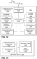
- FIG. 12 is a system diagram of an exemplary WTRU 1202, which may be employed as an encoder and/or decoder in embodiments described herein.
- the WTRU 1202 may include a processor 1218, a communication interface 1219 including a transceiver 1220, a transmit/receive element 1222, a speaker/microphone 1224, a keypad 1226, a display/touchpad 1228, a non-removable memory 1230, a removable memory 1232, a power source 1234, a global positioning system (GPS) chipset 1236, and sensors 1238.
- GPS global positioning system
- the processor 1218 may be a general purpose processor, a special purpose processor, a conventional processor, a digital signal processor (DSP), a plurality of microprocessors, one or more microprocessors in association with a DSP core, a controller, a microcontroller, Application Specific Integrated Circuits (ASICs), Field Programmable Gate Array (FPGAs) circuits, any other type of integrated circuit (IC), a state machine, and the like.
- the processor 1218 may perform signal coding, data processing, power control, input/output processing, and/or any other functionality that enables the WTRU 1202 to operate in a wireless environment.
- the processor 1218 may be coupled to the transceiver 1220, which may be coupled to the transmit/receive element 1222. While FIG. 6 depicts the processor 1218 and the transceiver 1220 as separate components, it will be appreciated that the processor 1218 and the transceiver 1220 may be integrated together in an electronic package or chip.
- the transmit/receive element 1222 may be configured to transmit signals to, or receive signals from, a base station over the air interface 1216.
- the transmit/receive element 1222 may be an antenna configured to transmit and/or receive RF signals.
- the transmit/receive element 1222 may be an emitter/detector configured to transmit and/or receive IR, UV, or visible light signals, as examples.
- the transmit/receive element 1222 may be configured to transmit and receive both RF and light signals. It will be appreciated that the transmit/receive element 1222 may be configured to transmit and/or receive any combination of wireless signals.
- the WTRU 1202 may include any number of transmit/receive elements 1222. More specifically, the WTRU 1202 may employ MIMO technology. Thus, in one embodiment, the WTRU 1202 may include two or more transmit/receive elements 1222 (e.g., multiple antennas) for transmitting and receiving wireless signals over the air interface 1216.
- the transceiver 1220 may be configured to modulate the signals that are to be transmitted by the transmit/receive element 1222 and to demodulate the signals that are received by the transmit/receive element 1222.
- the WTRU 1202 may have multi-mode capabilities.
- the transceiver 1220 may include multiple transceivers for enabling the WTRU 1202 to communicate via multiple RATs, such as UTRA and IEEE 802.11, as examples.
- the processor 1218 of the WTRU 1202 may be coupled to, and may receive user input data from, the speaker/microphone 1224, the keypad 1226, and/or the display/touchpad 1228 (e.g., a liquid crystal display (LCD) display unit or organic light-emitting diode (OLED) display unit).
- the processor 1218 may also output user data to the speaker/microphone 1224, the keypad 1226, and/or the display/touchpad 1228.
- the processor 1218 may access information from, and store data in, any type of suitable memory, such as the non-removable memory 1230 and/or the removable memory 1232.
- the non-removable memory 1230 may include random-access memory (RAM), read-only memory (ROM), a hard disk, or any other type of memory storage device.
- the removable memory 1232 may include a subscriber identity module (SIM) card, a memory stick, a secure digital (SD) memory card, and the like.
- SIM subscriber identity module
- SD secure digital
- the processor 1218 may access information from, and store data in, memory that is not physically located on the WTRU 1202, such as on a server or a home computer (not shown).
- the processor 1218 may receive power from the power source 1234, and may be configured to distribute and/or control the power to the other components in the WTRU 1202.
- the power source 1234 may be any suitable device for powering the WTRU 1202.
- the power source 1234 may include one or more dry cell batteries (e.g., nickel-cadmium (NiCd), nickel-zinc (NiZn), nickel metal hydride (NiMH), lithium-ion (Li-ion), and the like), solar cells, fuel cells, and the like.
- the processor 1218 may also be coupled to the GPS chipset 1236, which may be configured to provide location information (e.g., longitude and latitude) regarding the current location of the WTRU 1202.
- location information e.g., longitude and latitude
- the WTRU 1202 may receive location information over the air interface 1216 from a base station and/or determine its location based on the timing of the signals being received from two or more nearby base stations. It will be appreciated that the WTRU 1202 may acquire location information by way of any suitable location-determination method while remaining consistent with an embodiment.
- the processor 1218 may further be coupled to other peripherals 1238, which may include one or more software and/or hardware modules that provide additional features, functionality and/or wired or wireless connectivity.
- the peripherals 1238 may include sensors such as an accelerometer, an e-compass, a satellite transceiver, a digital camera (for photographs or video), a universal serial bus (USB) port, a vibration device, a television transceiver, a hands free headset, a Bluetooth ® module, a frequency modulated (FM) radio unit, a digital music player, a media player, a video game player module, an Internet browser, and the like.
- sensors such as an accelerometer, an e-compass, a satellite transceiver, a digital camera (for photographs or video), a universal serial bus (USB) port, a vibration device, a television transceiver, a hands free headset, a Bluetooth ® module, a frequency modulated (FM) radio unit, a digital music player, a media player, a video game
- FIG. 13 depicts an exemplary network entity 1390 that may be used in embodiments of the present disclosure.
- network entity 1390 includes a communication interface 1392, a processor 1394, and non-transitory data storage 1396, all of which are communicatively linked by a bus, network, or other communication path 1398.
- Communication interface 1392 may include one or more wired communication interfaces and/or one or more wireless-communication interfaces. With respect to wired communication, communication interface 1392 may include one or more interfaces such as Ethernet interfaces, as an example. With respect to wireless communication, communication interface 1392 may include components such as one or more antennae, one or more transceivers/chipsets designed and configured for one or more types of wireless (e.g., LTE) communication, and/or any other components deemed suitable by those of skill in the relevant art. And further with respect to wireless communication, communication interface 1392 may be equipped at a scale and with a configuration appropriate for acting on the network side-as opposed to the client side-of wireless communications (e.g., LTE communications, Wi-Fi communications, and the like). Thus, communication interface 1392 may include the appropriate equipment and circuitry (perhaps including multiple transceivers) for serving multiple mobile stations, UEs, or other access terminals in a coverage area.
- wireless communication interface 1392 may include the appropriate equipment and circuitry (perhaps including multiple transceivers
- Processor 1394 may include one or more processors of any type deemed suitable by those of skill in the relevant art, some examples including a general-purpose microprocessor and a dedicated DSP.
- Data storage 1396 may take the form of any non-transitory computer-readable medium or combination of such media, some examples including flash memory, read-only memory (ROM), and random-access memory (RAM) to name but a few, as any one or more types of non-transitory data storage deemed suitable by those of skill in the relevant art could be used.
- data storage 1396 contains program instructions 1397 executable by processor 1394 for carrying out various combinations of the various network-entity functions described herein.
- FIG. 14 is a schematic diagram illustrating an example of a coded bitstream structure.
- a coded bitstream 1400 consists of a number of NAL (Network Abstraction layer) units 1401.
- a NAL unit may contain coded sample data such as coded slice 1406, or high level syntax metadata such as parameter set data, slice header data 1405 or supplemental enhancement information data 1407 (which may be referred to as an SEI message).
- Parameter sets are high level syntax structures containing essential syntax elements that may apply to multiple bitstream layers (e.g., video parameter set 1402 (VPS)), or may apply to a coded video sequence within one layer (e.g., sequence parameter set 1403 (SPS)), or may apply to a number of coded pictures within one coded video sequence (e.g., picture parameter set 1404 (PPS)).
- the parameter sets can be either sent together with the coded pictures of the video bit stream, or sent through other means (including out-of-band transmission using reliable channels, hard coding, etc.).
- Slice header 1405 is also a high level syntax structure that may contain some picture-related information that is relatively small or relevant only for certain slice or picture types.
- SEI messages 1407 carry the information that may not be needed by the decoding process but can be used for various other purposes such as picture output timing or display as well as loss detection and concealment.
- FIG. 15 is a schematic diagram illustrating an example of a communication system.
- the communication system 1500 may comprise an encoder 1502, a communication network 1504, and a decoder 1506.
- the encoder 1502 may be in communication with the network 1504 via a connection 1508, which may be a wireline connection or a wireless connection.
- the encoder 1502 may be similar to the block-based video encoder of FIG. 1 .
- the encoder 1502 may include a single layer codec or a multilayer codec.
- the encoder 1502 may be a multi-layer (e.g., two-layer) scalable coding system with picture-level ILP support.
- the decoder 1506 may be in communication with the network 1504 via a connection 1510, which may be a wireline connection or a wireless connection.
- the decoder 1506 may be similar to the block-based video decoder of FIG. 2 .
- the decoder 1506 may include a single layer codec or a multilayer codec.
- the decoder 1506 may be a multi-layer (e.g., two-layer) scalable decoding system with picture-level ILP support.
- the encoder 1502 and/or the decoder 1506 may be incorporated into a wide variety of wired communication devices and/or wireless transmit/receive units (WTRUs), such as, but not limited to, digital televisions, wireless broadcast systems, a network element/terminal, servers, such as content or web servers (e.g., such as a Hypertext Transfer Protocol (HTTP) server), personal digital assistants (PDAs), laptop or desktop computers, tablet computers, digital cameras, digital recording devices, video gaming devices, video game consoles, cellular or satellite radio telephones, digital media players, and/or the like.
- WTRUs wireless transmit/receive units
- the communications network 1504 may be a suitable type of communication network.
- the communications network 1504 may be a multiple access system that provides content, such as voice, data, video, messaging, broadcast, etc., to multiple wireless users.
- the communications network 1504 may enable multiple wireless users to access such content through the sharing of system resources, including wireless bandwidth.
- the communications network 1504 may employ one or more channel access methods, such as code division multiple access (CDMA), time division multiple access (TDMA), frequency division multiple access (FDMA), orthogonal FDMA (OFDMA), single-carrier FDMA (SC-FDMA), and/or the like.
- the communication network 1504 may include multiple connected communication networks.
- the communication network 1504 may include the Internet and/or one or more private commercial networks such as cellular networks, WiFi hotspots, Internet Service Provider (ISP) networks, and/or the like.
- ISP Internet Service Provider
- ROM read only memory
- RAM random access memory
- register cache memory
- semiconductor memory devices magnetic media such as internal hard disks and removable disks, magneto-optical media, and optical media such as CD-ROM disks, and digital versatile disks (DVDs).
- a processor in association with software may be used to implement a radio frequency transceiver for use in a WTRU, UE, terminal, base station, RNC, or any host computer.
Landscapes
- Engineering & Computer Science (AREA)
- Multimedia (AREA)
- Signal Processing (AREA)
- Compression Or Coding Systems Of Tv Signals (AREA)
Claims (14)
- Verfahren zum Codieren eines Videos in einen Bitstrom unter Verwendung decodiererseitiger Intramodusderivation, wobei das Video mehrere Frames umfasst, wobei jeder Frame Blöcke von Abtastungen umfasst, wobei das Verfahren umfasst:Bestimmen von Kosten des Verwendens jeweiliger in Frage kommender Intravorhersagemodi zum Vorhersagen von Abtastungen in einer Schablonenregion neben einem momentanen Block eines Videoframes, wobei das Bestimmen der Kosten umfasst:auf einer anfänglichen Stufe, Bestimmen von Kosten des Verwendens jeweiliger Intravorhersagemodi anhand eines anfänglichen Satzes in Frage kommender Modi, wobei Indexnummern, die jeweils mit den in Frage kommenden Modi in dem anfänglichen Satz verknüpft sind, durch ein anfängliches Intervall getrennt werden, undauf mindestens einer anschließenden Stufe, Bestimmen von Kosten des Verwendens jeweiliger Intravorhersagemodi anhand eines anschließenden Satzes in Frage kommender Modi, wobei der anschließende Satz in Frage kommender Modi auf der Grundlage des in Frage kommenden Modus in der vorherigen Stufe, der die niedrigsten Kosten hat, ausgewählt wird, wobei Indexnummern, die jeweils mit den in Frage kommenden Modi in dem anschließenden Satz verknüpft sind, durch ein anschließendes Intervall getrennt werden, das kleiner ist als das in der vorherigen Stufe verwendete Intervall;Ableiten eines Intravorhersagemodus, der die niedrigsten Kosten hat, unter den in Frage kommenden Intravorhersagemodi, wobei der abgeleitete Modus in einer Liste der wahrscheinlichsten Modi enthalten ist, und wobei ein Index in den Bitstrom codiert wird, der den abgeleiteten Modus aus der Liste der wahrscheinlichsten Modi identifiziert; undVorhersagen der Abtastungen in dem momentanen Block unter Verwendung des abgeleiteten Intravorhersagemodus, wobei der anschließende Satz in Frage kommender Modi auf den in Frage kommenden Modus in der vorherigen Stufe, der die niedrigsten Kosten hat, zentriert ist.
- Vorrichtung zum Codieren eines Videos in einen Bitstrom unter Verwendung decodiererseitiger Intramodusderivation, wobei das Video mehrere Frames umfasst, wobei jeder Frame Blöcke von Abtastungen umfasst, wobei die Vorrichtung mindestens einen Prozessor umfasst, der zum Durchführen von Folgendem eingerichtet ist:Bestimmen von Kosten des Verwendens jeweiliger in Frage kommender Intravorhersagemodi zum Vorhersagen von Abtastungen in einer Schablonenregion neben einem momentanen Block eines Videoframes, wobei das Bestimmen der Kosten umfasst:auf einer anfänglichen Stufe, Bestimmen von Kosten des Verwendens jeweiliger Intravorhersagemodi anhand eines anfänglichen Satzes in Frage kommender Modi, wobei Indexnummern, die jeweils mit den in Frage kommenden Modi in dem anfänglichen Satz verknüpft sind, durch ein anfängliches Intervall getrennt werden, undauf mindestens einer anschließenden Stufe, Bestimmen von Kosten des Verwendens jeweiliger Intravorhersagemodi anhand eines anschließenden Satzes in Frage kommender Modi, wobei der anschließende Satz in Frage kommender Modi auf der Grundlage des in Frage kommenden Modus in der vorherigen Stufe, der die niedrigsten Kosten hat, ausgewählt wird, wobei Indexnummern, die jeweils mit den in Frage kommenden Modi in dem anschließenden Satz verknüpft sind, durch ein anschließendes Intervall getrennt werden, das kleiner ist als das in der vorherigen Stufe verwendete Intervall;Ableiten eines Intravorhersagemodus, der die niedrigsten Kosten hat, unter den in Frage kommenden Intravorhersagemodi, wobei der abgeleitete Modus in einer Liste der wahrscheinlichsten Modi enthalten ist, und wobei ein Index in den Bitstrom codiert wird, der den abgeleiteten Modus aus der Liste der wahrscheinlichsten Modi identifiziert; undVorhersagen der Abtastungen in dem momentanen Block unter Verwendung des abgeleiteten Intravorhersagemodus, wobei der anschließende Satz in Frage kommender Modi auf den in Frage kommenden Modus in der vorherigen Stufe, der die niedrigsten Kosten hat, zentriert ist.
- Computerlesbares Medium, das Instruktionen speichert, um mindestens einen Prozessor zu veranlassen, ein Verfahren zum Codieren eines Videos in einen Bitstrom unter Verwendung decodiererseitiger Intramodusderivation durchzuführen, wobei das Video mehrere Frames umfasst, wobei jeder Frame Blöcke von Abtastungen umfasst, wobei das Verfahren umfasst:Bestimmen von Kosten des Verwendens jeweiliger in Frage kommender Intravorhersagemodi zum Vorhersagen von Abtastungen in einer Schablonenregion neben einem momentanen Block eines Videoframes, wobei das Bestimmen der Kosten umfasst:auf einer anfänglichen Stufe, Bestimmen von Kosten des Verwendens jeweiliger Intravorhersagemodi anhand eines anfänglichen Satzes in Frage kommender Modi, wobei Indexnummern, die jeweils mit den in Frage kommenden Modi in dem anfänglichen Satz verknüpft sind, durch ein anfängliches Intervall getrennt werden, undauf mindestens einer anschließenden Stufe, Bestimmen von Kosten des Verwendens jeweiliger Intravorhersagemodi anhand eines anschließenden Satzes in Frage kommender Modi, wobei der anschließende Satz in Frage kommender Modi auf der Grundlage des in Frage kommenden Modus in der vorherigen Stufe, der die niedrigsten Kosten hat, ausgewählt wird, wobei Indexnummern, die jeweils mit den in Frage kommenden Modi in dem anschließenden Satz verknüpft sind, durch ein anschließendes Intervall getrennt werden, das kleiner ist als das in der vorherigen Stufe verwendete Intervall;Ableiten eines Intravorhersagemodus, der die niedrigsten Kosten hat, unter den in Frage kommenden Intravorhersagemodi, wobei der abgeleitete Modus in einer Liste der wahrscheinlichsten Modi enthalten ist, und wobei ein Index in den Bitstrom codiert wird, der den abgeleiteten Modus aus der Liste der wahrscheinlichsten Modi identifiziert; undVorhersagen der Abtastungen in dem momentanen Block unter Verwendung des abgeleiteten Intravorhersagemodus, wobei der anschließende Satz in Frage kommender Modi auf den in Frage kommenden Modus in der vorherigen Stufe, der die niedrigsten Kosten hat, zentriert ist.
- Verfahren nach Anspruch 1, Vorrichtung nach Anspruch 2 oder Medium nach Anspruch 3, wobei jede der ermittelten Kosten ein Maß der Verzerrung zwischen der Schablonenregion und einer Vorhersage der Schablonenregion unter Verwendung eines jeweiligen in Frage kommenden Intravorhersagemodus ist.
- Verfahren nach Anspruch 1, Vorrichtung nach Anspruch 2 oder Medium nach Anspruch 3, wobei die Schablonenregion rekonstruierte Abtastungen umfasst und die Vorhersage der Schablonenregion auf einem Satz rekonstruierter Referenzabtastungen basiert.
- Verfahren nach Anspruch 1, Vorrichtung nach Anspruch 2 oder Medium nach Anspruch 3, wobei Vorhersagereste für die Abtastungen in dem momentanen Block unter Verwendung einer Transformationskoeffizienten-Abtastreihenfolge in den Bitstrom codiert werden, und wobei die Transformationskoeffizienten-Abtastreihenfolge unabhängig von dem abgeleiteten Modus ist.
- Verfahren nach Anspruch 6, soweit abhängig von Anspruch 1, Vorrichtung nach Anspruch 6, soweit abhängig von Anspruch 2, oder Medium nach Anspruch 6, soweit abhängig von Anspruch 3, wobei die Transformationskoeffizienten-Abtastreihenfolge eine zuvor festgelegte Abtastreihenfolge ist.
- Verfahren zum Decodieren eines Videos aus einem Bitstrom unter Verwendung decodiererseitiger Intramodusderivation, wobei das Video mehrere Frames umfasst, wobei jeder Frame Blöcke von Abtastungen umfasst, wobei das Verfahren umfasst:Bestimmen von Kosten des Verwendens jeweiliger in Frage kommender Intravorhersagemodi zum Vorhersagen von Abtastungen in einer Schablonenregion neben einem momentanen Block eines Videoframes, wobei das Bestimmen der Kosten umfasst:auf einer anfänglichen Stufe, Bestimmen von Kosten des Verwendens jeweiliger Intravorhersagemodi anhand eines anfänglichen Satzes in Frage kommender Modi, wobei Indexnummern, die jeweils mit den in Frage kommenden Modi in dem anfänglichen Satz verknüpft sind, durch ein anfängliches Intervall getrennt werden, undauf mindestens einer anschließenden Stufe, Bestimmen von Kosten des Verwendens jeweiliger Intravorhersagemodi anhand eines anschließenden Satzes in Frage kommender Modi, wobei der anschließende Satz in Frage kommender Modi auf der Grundlage des in Frage kommenden Modus in der vorherigen Stufe, der die niedrigsten Kosten hat, ausgewählt wird, wobei Indexnummern, die jeweils mit den in Frage kommenden Modi in dem anschließenden Satz verknüpft sind, durch ein anschließendes Intervall getrennt werden, das kleiner ist als das in der vorherigen Stufe verwendete Intervall;Ableiten eines Intravorhersagemodus, der die niedrigsten Kosten hat, unter den in Frage kommenden Intravorhersagemodi, wobei der abgeleitete Modus in einer Liste der wahrscheinlichsten Modi enthalten ist, und wobei ein Index aus dem Bitstrom decodiert wird, der den abgeleiteten Modus aus der Liste der wahrscheinlichsten Modi identifiziert; undVorhersagen der Abtastungen in dem momentanen Block unter Verwendung des abgeleiteten Intravorhersagemodus, wobei der anschließende Satz in Frage kommender Modi auf den in Frage kommenden Modus in der vorherigen Stufe, der die niedrigsten Kosten hat, zentriert ist.
- Vorrichtung zum Decodieren eines Videos aus einem Bitstrom unter Verwendung decodiererseitiger Intramodusderivation, wobei das Video mehrere Frames umfasst, wobei jeder Frame Blöcke von Abtastungen umfasst, wobei die Vorrichtung mindestens einen Prozessor umfasst, der zum Durchführen von Folgendem eingerichtet ist:Bestimmen von Kosten des Verwendens jeweiliger in Frage kommender Intravorhersagemodi zum Vorhersagen von Abtastungen in einer Schablonenregion neben einem momentanen Block eines Videoframes, wobei das Bestimmen der Kosten umfasst:auf einer anfänglichen Stufe, Bestimmen von Kosten des Verwendens jeweiliger Intravorhersagemodi anhand eines anfänglichen Satzes in Frage kommender Modi, wobei Indexnummern, die jeweils mit den in Frage kommenden Modi in dem anfänglichen Satz verknüpft sind, durch ein anfängliches Intervall getrennt werden, undauf mindestens einer anschließenden Stufe, Bestimmen von Kosten des Verwendens jeweiliger Intravorhersagemodi anhand eines anschließenden Satzes in Frage kommender Modi, wobei der anschließende Satz in Frage kommender Modi auf der Grundlage des in Frage kommenden Modus in der vorherigen Stufe, der die niedrigsten Kosten hat, ausgewählt wird, wobei Indexnummern, die jeweils mit den in Frage kommenden Modi in dem anschließenden Satz verknüpft sind, durch ein anschließendes Intervall getrennt werden, das kleiner ist als das in der vorherigen Stufe verwendete Intervall;Ableiten eines Intravorhersagemodus, der die niedrigsten Kosten hat, unter den in Frage kommenden Intravorhersagemodi, wobei der abgeleitete Modus in einer Liste der wahrscheinlichsten Modi enthalten ist, und wobei ein Index aus dem Bitstrom decodiert wird, der den abgeleiteten Modus aus der Liste der wahrscheinlichsten Modi identifiziert; undVorhersagen der Abtastungen in dem momentanen Block unter Verwendung des abgeleiteten Intravorhersagemodus, wobei der anschließende Satz in Frage kommender Modi auf den in Frage kommenden Modus in der vorherigen Stufe, der die niedrigsten Kosten hat, zentriert ist.
- Computerlesbares Medium, das Instruktionen speichert, um mindestens einen Prozessor zu veranlassen, ein Verfahren zum Decodieren eines Videos aus einem Bitstrom unter Verwendung decodiererseitiger Intramodusderivation durchzuführen, wobei das Video mehrere Frames umfasst, wobei jeder Frame Blöcke von Abtastungen umfasst, wobei das Verfahren umfasst:Bestimmen von Kosten des Verwendens jeweiliger in Frage kommender Intravorhersagemodi zum Vorhersagen von Abtastungen in einer Schablonenregion neben einem momentanen Block eines Videoframes, wobei das Bestimmen der Kosten umfasst:auf einer anfänglichen Stufe, Bestimmen von Kosten des Verwendens jeweiliger Intravorhersagemodi anhand eines anfänglichen Satzes in Frage kommender Modi, wobei Indexnummern, die jeweils mit den in Frage kommenden Modi in dem anfänglichen Satz verknüpft sind, durch ein anfängliches Intervall getrennt werden, undauf mindestens einer anschließenden Stufe, Bestimmen von Kosten des Verwendens jeweiliger Intravorhersagemodi anhand eines anschließenden Satzes in Frage kommender Modi, wobei der anschließende Satz in Frage kommender Modi auf der Grundlage des in Frage kommenden Modus in der vorherigen Stufe, der die niedrigsten Kosten hat, ausgewählt wird, wobei Indexnummern, die jeweils mit den in Frage kommenden Modi in dem anschließenden Satz verknüpft sind, durch ein anschließendes Intervall getrennt werden, das kleiner ist als das in der vorherigen Stufe verwendete Intervall;Ableiten eines Intravorhersagemodus, der die niedrigsten Kosten hat, unter den in Frage kommenden Intravorhersagemodi, wobei der abgeleitete Modus in einer Liste der wahrscheinlichsten Modi enthalten ist, und wobei ein Index aus dem Bitstrom decodiert wird, der den abgeleiteten Modus aus der Liste der wahrscheinlichsten Modi identifiziert; undVorhersagen der Abtastungen in dem momentanen Block unter Verwendung des abgeleiteten Intravorhersagemodus, wobei der anschließende Satz in Frage kommender Modi auf den in Frage kommenden Modus in der vorherigen Stufe, der die niedrigsten Kosten hat, zentriert ist.
- Verfahren nach Anspruch 8, Vorrichtung nach Anspruch 9 oder Medium nach Anspruch 10, wobei jede der ermittelten Kosten ein Maß der Verzerrung zwischen der Schablonenregion und einer Vorhersage der Schablonenregion unter Verwendung eines jeweiligen in Frage kommenden Intravorhersagemodus ist.
- Verfahren nach Anspruch 8, Vorrichtung nach Anspruch 9 oder Medium nach Anspruch 10, wobei die Schablonenregion rekonstruierte Abtastungen umfasst und die Vorhersage der Schablonenregion auf einem Satz rekonstruierter Referenzabtastungen basiert.
- Verfahren nach Anspruch 8, Vorrichtung nach Anspruch 9 oder Medium nach Anspruch 10, wobei Vorhersagereste für die Abtastungen in dem momentanen Block unter Verwendung einer Transformationskoeffizienten-Abtastreihenfolge aus dem Bitstrom decodiert werden, und wobei die Transformationskoeffizienten-Abtastreihenfolge unabhängig von dem abgeleiteten Modus ist.
- Verfahren nach Anspruch 13, soweit abhängig von Anspruch 8, Vorrichtung nach Anspruch 13, soweit abhängig von Anspruch 9, oder Medium nach Anspruch 13, soweit abhängig von Anspruch 10, wobei die Transformationskoeffizienten-Abtastreihenfolge eine zuvor festgelegte Abtastreihenfolge ist.
Priority Applications (1)
| Application Number | Priority Date | Filing Date | Title |
|---|---|---|---|
| EP24209942.2A EP4518317A1 (de) | 2016-05-06 | 2017-05-05 | Verfahren und system für decodiererseitige intra-modus ableitung zur blockbasierten videocodierung |
Applications Claiming Priority (4)
| Application Number | Priority Date | Filing Date | Title |
|---|---|---|---|
| US201662332871P | 2016-05-06 | 2016-05-06 | |
| US201662335512P | 2016-05-12 | 2016-05-12 | |
| US201662367414P | 2016-07-27 | 2016-07-27 | |
| PCT/US2017/031303 WO2017192995A1 (en) | 2016-05-06 | 2017-05-05 | Method and system for decoder-side intra mode derivation for block-based video coding |
Related Child Applications (1)
| Application Number | Title | Priority Date | Filing Date |
|---|---|---|---|
| EP24209942.2A Division EP4518317A1 (de) | 2016-05-06 | 2017-05-05 | Verfahren und system für decodiererseitige intra-modus ableitung zur blockbasierten videocodierung |
Publications (2)
| Publication Number | Publication Date |
|---|---|
| EP3453174A1 EP3453174A1 (de) | 2019-03-13 |
| EP3453174B1 true EP3453174B1 (de) | 2024-11-27 |
Family
ID=58710110
Family Applications (2)
| Application Number | Title | Priority Date | Filing Date |
|---|---|---|---|
| EP17724201.3A Active EP3453174B1 (de) | 2016-05-06 | 2017-05-05 | Verfahren und system für decodiererseitige intra-modus ableitung zur blockbasierten videocodierung |
| EP24209942.2A Pending EP4518317A1 (de) | 2016-05-06 | 2017-05-05 | Verfahren und system für decodiererseitige intra-modus ableitung zur blockbasierten videocodierung |
Family Applications After (1)
| Application Number | Title | Priority Date | Filing Date |
|---|---|---|---|
| EP24209942.2A Pending EP4518317A1 (de) | 2016-05-06 | 2017-05-05 | Verfahren und system für decodiererseitige intra-modus ableitung zur blockbasierten videocodierung |
Country Status (3)
| Country | Link |
|---|---|
| US (3) | US11722677B2 (de) |
| EP (2) | EP3453174B1 (de) |
| WO (1) | WO2017192995A1 (de) |
Families Citing this family (136)
| Publication number | Priority date | Publication date | Assignee | Title |
|---|---|---|---|---|
| JP2019519972A (ja) | 2016-05-05 | 2019-07-11 | ヴィド スケール インコーポレイテッド | イントラコーディングのための制御点ベースのイントラ方向表現 |
| EP3453174B1 (de) * | 2016-05-06 | 2024-11-27 | InterDigital Madison Patent Holdings, SAS | Verfahren und system für decodiererseitige intra-modus ableitung zur blockbasierten videocodierung |
| FR3053555A1 (fr) * | 2016-06-29 | 2018-01-05 | B<>Com | Procede de codage d'une image numerique, procede de decodage, dispositifs, terminal et programmes d'ordinateurs associes |
| US10368107B2 (en) | 2016-08-15 | 2019-07-30 | Qualcomm Incorporated | Intra video coding using a decoupled tree structure |
| EP3910954A1 (de) * | 2016-08-26 | 2021-11-17 | SHARP Kabushiki Kaisha | Bilddecodierungsvorrichtung, bildcodierungsvorrichtung |
| US10951912B2 (en) | 2016-10-05 | 2021-03-16 | Qualcomm Incorporated | Systems and methods for adaptive selection of weights for video coding |
| KR102719084B1 (ko) * | 2017-01-02 | 2024-10-16 | 한양대학교 산학협력단 | 참조 화소에 대하여 적응적 필터링을 수행하기 위한 화면 내 예측 방법 및 장치 |
| US12184846B2 (en) | 2017-01-02 | 2024-12-31 | Industry-University Cooperation Foundation Hanyang University | Intra prediction method and apparatus for performing adaptive filtering on reference pixel |
| JPWO2018173798A1 (ja) * | 2017-03-23 | 2020-01-23 | ソニー株式会社 | 画像処理装置および方法 |
| US20180288439A1 (en) * | 2017-03-31 | 2018-10-04 | Mediatek Inc. | Multiple Transform Prediction |
| WO2019007490A1 (en) * | 2017-07-04 | 2019-01-10 | Huawei Technologies Co., Ltd. | DECODER INTEGRATED MODE (DIMD) INTEGRATED DEVICE TOOL CALCULATION COMPLEXITY REDUCTION |
| WO2019007492A1 (en) * | 2017-07-04 | 2019-01-10 | Huawei Technologies Co., Ltd. | INTRAMODE BYPASS LINE MEMORY HARMONIZATION DECODER SIDE WITH UNBLOCKING FILTER |
| US10757442B2 (en) * | 2017-07-05 | 2020-08-25 | Qualcomm Incorporated | Partial reconstruction based template matching for motion vector derivation |
| US10628165B2 (en) * | 2017-08-17 | 2020-04-21 | Agora Lab, Inc. | Gain control for multiple description coding |
| EP3709642A4 (de) * | 2017-11-09 | 2020-09-16 | Sony Corporation | Bildverarbeitungsvorrichtung und bildverarbeitungsverfahren |
| WO2019117634A1 (ko) * | 2017-12-15 | 2019-06-20 | 엘지전자 주식회사 | 2차 변환에 기반한 영상 코딩 방법 및 그 장치 |
| US10715810B2 (en) * | 2018-02-20 | 2020-07-14 | Qualcomm Incorporated | Simplified local illumination compensation |
| GB2571311B (en) * | 2018-02-23 | 2021-08-18 | Canon Kk | Methods and devices for improvement in obtaining linear component sample prediction parameters |
| US10771781B2 (en) * | 2018-03-12 | 2020-09-08 | Electronics And Telecommunications Research Institute | Method and apparatus for deriving intra prediction mode |
| US11611757B2 (en) | 2018-04-02 | 2023-03-21 | Qualcomm Incorproated | Position dependent intra prediction combination extended with angular modes |
| WO2019194440A1 (ko) * | 2018-04-02 | 2019-10-10 | 엘지전자 주식회사 | 인트라 예측 모드에 대한 룩업 테이블을 이용한 영상 코딩 방법 및 그 장치 |
| CN110213576B (zh) * | 2018-05-03 | 2023-02-28 | 腾讯科技(深圳)有限公司 | 视频编码方法、视频编码装置、电子设备及存储介质 |
| US11451773B2 (en) | 2018-06-01 | 2022-09-20 | Qualcomm Incorporated | Block-based adaptive loop filter (ALF) design and signaling |
| JP2019213096A (ja) * | 2018-06-06 | 2019-12-12 | Kddi株式会社 | 画像復号装置、画像符号化装置、画像処理システム、画像復号方法及びプログラム |
| US11128872B2 (en) | 2018-07-16 | 2021-09-21 | Qualcomm Incorporated | Position dependent intra prediction combination with wide angle intra prediction |
| US10630979B2 (en) * | 2018-07-16 | 2020-04-21 | Tencent America LLC | Reference sample padding and filtering for intra prediction in video compression |
| US10911765B2 (en) * | 2018-08-01 | 2021-02-02 | Tencent America LLC | Method and apparatus for video coding |
| US11284075B2 (en) | 2018-09-12 | 2022-03-22 | Qualcomm Incorporated | Prediction of adaptive loop filter parameters with reduced memory consumption for video coding |
| TWI863927B (zh) * | 2018-09-19 | 2024-12-01 | 大陸商北京字節跳動網絡技術有限公司 | 用於幀內編解碼的鄰近的相鄰塊的選擇 |
| US10469845B1 (en) * | 2018-09-21 | 2019-11-05 | Tencent America, Llc | Method and apparatus for intra mode coding |
| EP3709644A1 (de) * | 2019-03-12 | 2020-09-16 | Ateme | Verfahren zur bildverarbeitung und vorrichtung zur implementierung davon |
| EP3629579A1 (de) * | 2018-09-27 | 2020-04-01 | Ateme | Verfahren zur bildverarbeitung und vorrichtung zur implementierung des verfahrens |
| JP6874804B2 (ja) * | 2018-09-28 | 2021-05-19 | 株式会社Jvcケンウッド | 画像復号装置、画像復号方法、及び画像復号プログラム |
| US11671589B2 (en) | 2020-12-22 | 2023-06-06 | Qualcomm Incorporated | Decoder side intra mode derivation for most probable mode list construction in video coding |
| US11051017B2 (en) * | 2018-12-20 | 2021-06-29 | Qualcomm Incorporated | Adaptive loop filter (ALF) index signaling |
| CN116456083B (zh) * | 2018-12-25 | 2026-04-07 | Oppo广东移动通信有限公司 | 解码预测方法、装置及计算机存储介质 |
| US11102490B2 (en) * | 2018-12-31 | 2021-08-24 | Tencent America LLC | Coefficient scanning methods on adaptive angle mode |
| KR20250108746A (ko) | 2019-01-02 | 2025-07-15 | 광동 오포 모바일 텔레커뮤니케이션즈 코포레이션 리미티드 | 예측 방향 결정 방법, 디코더 및 컴퓨터 저장 매체 |
| KR20210114386A (ko) | 2019-02-08 | 2021-09-23 | 주식회사 윌러스표준기술연구소 | 이차 변환을 이용하는 비디오 신호 처리 방법 및 장치 |
| US10778972B1 (en) * | 2019-02-27 | 2020-09-15 | Google Llc | Adaptive filter intra prediction modes in image/video compression |
| CN118694972A (zh) | 2019-02-28 | 2024-09-24 | 数码士有限公司 | 基于帧内预测的视频信号处理方法和装置 |
| AU2019201649A1 (en) * | 2019-03-11 | 2020-10-01 | Canon Kabushiki Kaisha | Method, apparatus and system for encoding and decoding a tree of blocks of video samples |
| AU2019201653A1 (en) | 2019-03-11 | 2020-10-01 | Canon Kabushiki Kaisha | Method, apparatus and system for encoding and decoding a tree of blocks of video samples |
| CN114040205B (zh) * | 2019-03-12 | 2025-06-24 | 浙江大华技术股份有限公司 | 帧内色度预测模式的选择方法、图像处理设备及存储设备 |
| WO2020182167A1 (en) * | 2019-03-12 | 2020-09-17 | Zhejiang Dahua Technology Co., Ltd. | Systems and methods for image coding |
| JP7410168B2 (ja) * | 2019-03-14 | 2024-01-09 | エルジー エレクトロニクス インコーポレイティド | イントラ予測を行う画像符号化/復号方法、装置、およびビットストリームを伝送する方法 |
| US11405638B2 (en) * | 2019-03-17 | 2022-08-02 | Tencent America LLC | Method and apparatus for video coding by determining intra prediction direction based on coded information of neighboring blocks |
| WO2020197038A1 (ko) | 2019-03-22 | 2020-10-01 | 엘지전자 주식회사 | 영상 코딩 시스템에서 인트라 서브 파티션 기반의 인트라 예측 방법 및 장치 |
| CN113728640B (zh) | 2019-04-23 | 2024-08-02 | 北京字节跳动网络技术有限公司 | 帧内预测和残差编解码 |
| KR20220002904A (ko) | 2019-05-02 | 2022-01-07 | 베이징 바이트댄스 네트워크 테크놀로지 컴퍼니, 리미티드 | 다중 레퍼런스 필터를 사용한 인트라 비디오 코딩 |
| CN113841409B (zh) | 2019-05-10 | 2023-12-19 | 北京字节跳动网络技术有限公司 | 用于视频处理的简化二次变换的有条件使用 |
| EP3949403A4 (de) | 2019-05-11 | 2022-06-22 | Beijing Bytedance Network Technology Co., Ltd. | Wechselwirkungen zwischen mehreren intracodierenden verfahren |
| US11375236B2 (en) * | 2019-05-22 | 2022-06-28 | Tencent America LLC | Method and apparatus for video coding |
| KR20250040743A (ko) | 2019-05-31 | 2025-03-24 | 바이트댄스 아이엔씨 | 인트라 블록 복사 예측을 갖는 팔레트 모드 |
| CN112019841A (zh) * | 2019-05-31 | 2020-12-01 | 富士通株式会社 | 视频编码方法及装置、电子设备 |
| CN113950828B (zh) | 2019-06-07 | 2024-07-05 | 北京字节跳动网络技术有限公司 | 视频比特流中的简化二次变换的有条件信令 |
| GB2585030A (en) * | 2019-06-25 | 2020-12-30 | British Broadcasting Corp | Method of signalling in a video codec |
| WO2020264457A1 (en) | 2019-06-28 | 2020-12-30 | Bytedance Inc. | Techniques for modifying quantization parameter in transform skip mode |
| CN114072849B (zh) | 2019-06-28 | 2023-12-15 | 字节跳动有限公司 | 屏幕内容编解码中的色度帧内模式推导 |
| EP3817390A4 (de) | 2019-07-10 | 2021-09-29 | Guangdong Oppo Mobile Telecommunications Corp., Ltd. | Bildkomponentenvorhersageverfahren, codierer, decodierer und speichermedium |
| WO2021023151A1 (en) | 2019-08-03 | 2021-02-11 | Beijing Bytedance Network Technology Co., Ltd. | Position based mode derivation in reduced secondary transforms for video |
| CN114287133B (zh) * | 2019-08-14 | 2024-09-10 | 北京字节跳动网络技术有限公司 | 帧内模式中的预测样点滤波的加权因子 |
| CN117376556A (zh) | 2019-08-14 | 2024-01-09 | 北京字节跳动网络技术有限公司 | 位置相关帧内预测样点滤波 |
| CN118632034A (zh) | 2019-08-17 | 2024-09-10 | 北京字节跳动网络技术有限公司 | 为视频中的缩减二次变换的边信息的上下文建模 |
| CN114270825B (zh) | 2019-08-19 | 2024-06-28 | 北京字节跳动网络技术有限公司 | 基于计数器的帧内预测模式的初始化 |
| CN114342408B (zh) * | 2019-08-26 | 2024-11-19 | 北京字节跳动网络技术有限公司 | 视频编码中帧内编码模式的扩展 |
| WO2021037258A1 (en) | 2019-08-30 | 2021-03-04 | Beijing Bytedance Network Technology Co., Ltd. | Sub-partitioning in intra coding |
| CN117615155A (zh) | 2019-09-19 | 2024-02-27 | 北京字节跳动网络技术有限公司 | 视频编解码中的参考样点位置推导 |
| WO2021055114A1 (en) * | 2019-09-20 | 2021-03-25 | Alibaba Group Holding Limited | Method and system for signaling chroma quantization parameter offset |
| CN114731434B (zh) | 2019-09-21 | 2023-06-30 | Lg电子株式会社 | 基于变换的图像编码方法及其装置 |
| CN117376557A (zh) | 2019-10-13 | 2024-01-09 | 北京字节跳动网络技术有限公司 | 参考图片重采样与视频编解码工具之间的相互作用 |
| JP7425204B2 (ja) | 2019-12-26 | 2024-01-30 | バイトダンス インコーポレイテッド | ビデオビットストリームにおける仮想参照デコーダパラメータのシグナリングに対する制約 |
| CN114902656B (zh) | 2019-12-26 | 2025-03-21 | 字节跳动有限公司 | 对编解码比特流中的视频层的信令的约束 |
| EP4066386A4 (de) | 2019-12-27 | 2023-01-25 | ByteDance Inc. | Unterbildsignalisierung in videocodierung |
| KR102922307B1 (ko) | 2019-12-27 | 2026-02-05 | 두인 비전 컴퍼니 리미티드 | 비디오 픽처 헤더의 슬라이스 유형의 시그널링 |
| CN119788855B (zh) * | 2019-12-31 | 2025-12-26 | Oppo广东移动通信有限公司 | 变换方法、编码器、解码器以及存储介质 |
| EP4074024A4 (de) | 2020-01-09 | 2023-04-05 | ByteDance Inc. | Signalisierung des vorhandenseins von zwischenschicht-referenzbildern |
| US11197001B2 (en) * | 2020-02-05 | 2021-12-07 | Tencent America LLC | Method and apparatus for interactions between decoder-side intra mode derivation and adaptive intra prediction modes |
| PH12022552344A1 (en) * | 2020-03-31 | 2023-11-29 | Ericsson Telefon Ab L M | Video processing using syntax elements |
| US12143620B2 (en) * | 2020-08-21 | 2024-11-12 | Alibaba Group Holding Limited | Filtering methods for angular intra prediction |
| CN116636209A (zh) * | 2020-12-22 | 2023-08-22 | 高通股份有限公司 | 视频译码中用于最可能模式列表构建的解码器侧帧内模式推导 |
| JP7819194B2 (ja) * | 2020-12-22 | 2026-02-24 | クゥアルコム・インコーポレイテッド | ビデオコーディングにおける最確モードリスト構築のためのデコーダ側イントラモード導出 |
| US12096030B2 (en) * | 2020-12-23 | 2024-09-17 | Tencent America LLC | Method and apparatus for video coding |
| US11388421B1 (en) * | 2021-01-13 | 2022-07-12 | Lemon Inc. | Usage of templates for decoder-side intra mode derivation |
| WO2022182174A1 (ko) * | 2021-02-24 | 2022-09-01 | 엘지전자 주식회사 | 인트라 예측 모드 도출 기반 인트라 예측 방법 및 장치 |
| CN113038179A (zh) * | 2021-02-26 | 2021-06-25 | 维沃移动通信有限公司 | 视频编码方法、视频解码方法、装置及电子设备 |
| KR20230169986A (ko) | 2021-04-11 | 2023-12-18 | 엘지전자 주식회사 | 복수의 dimd 모드 기반 인트라 예측 방법 및 장치 |
| US11943432B2 (en) * | 2021-04-26 | 2024-03-26 | Tencent America LLC | Decoder side intra mode derivation |
| WO2022242651A1 (en) * | 2021-05-17 | 2022-11-24 | Beijing Bytedance Network Technology Co., Ltd. | Method, device, and medium for video processing |
| US12537946B2 (en) | 2021-05-19 | 2026-01-27 | Beijing Bytedance Network Technology Co., Ltd. | Method, device, and medium for video processing |
| CN117581536A (zh) * | 2021-05-19 | 2024-02-20 | 抖音视界有限公司 | 用于视频处理的方法、设备和介质 |
| US12192469B2 (en) * | 2021-06-03 | 2025-01-07 | Qualcomm Incorporated | Derived intra prediction modes and most probable modes in video coding |
| WO2022260341A1 (ko) | 2021-06-11 | 2022-12-15 | 현대자동차주식회사 | 비디오 부호화/복호화 방법 및 장치 |
| US12375663B2 (en) * | 2021-06-27 | 2025-07-29 | Alibaba Innovation Private Limited | Methods and systems for performing combined inter and intra prediction |
| WO2023277535A1 (ko) * | 2021-06-28 | 2023-01-05 | 주식회사 윌러스표준기술연구소 | 인트라 예측을 이용한 비디오 신호 처리 방법 및 이를 위한 장치 |
| WO2023277577A1 (ko) * | 2021-06-30 | 2023-01-05 | 엘지전자 주식회사 | Mpm 리스트를 이용하는 인트라 예측 방법 및 장치 |
| US12160561B2 (en) | 2021-08-02 | 2024-12-03 | Tencent America LLC | Method and apparatus for improved intra prediction |
| CN116711309B (zh) * | 2021-08-02 | 2024-06-21 | 腾讯美国有限责任公司 | 用于改进的帧内预测的视频编解码方法和装置及电子设备 |
| EP4397036A4 (de) * | 2021-08-30 | 2025-07-09 | Beijing Dajia Internet Information Tech Co Ltd | Verfahren und vorrichtungen zur decodiererseitigen intramodusableitung |
| WO2023034629A1 (en) * | 2021-09-05 | 2023-03-09 | Beijing Dajia Internet Information Technology Co., Ltd. | Intra prediction modes signaling |
| WO2023036341A1 (en) * | 2021-09-13 | 2023-03-16 | FG Innovation Company Limited | Device and method for intra predictions in video coding |
| CN115866263A (zh) * | 2021-09-24 | 2023-03-28 | 维沃移动通信有限公司 | 视频解码方法、视频编码方法及相关设备 |
| CN117981300A (zh) * | 2021-09-27 | 2024-05-03 | Oppo广东移动通信有限公司 | 编解码方法、码流、编码器、解码器以及存储介质 |
| EP4383714A4 (de) * | 2021-09-27 | 2025-05-28 | Guangdong Oppo Mobile Telecommunications Corp., Ltd. | Intraprädiktionsverfahren, codierer, decodierer und codierungs-/decodierungssystem |
| CN117981299A (zh) | 2021-09-27 | 2024-05-03 | Oppo广东移动通信有限公司 | 帧内预测的方法、编码器、解码器和编解码系统 |
| EP4409885A1 (de) * | 2021-09-28 | 2024-08-07 | Ofinno, LLC | Decodiererseitige ableitung des intraprädiktionsmodus mit erweiterten winkelmodi |
| CN115883833B (zh) * | 2021-09-28 | 2025-07-22 | 维沃移动通信有限公司 | 帧内预测方法及装置 |
| JP7837402B2 (ja) * | 2021-09-29 | 2026-03-30 | ベイジン、ターチア、インターネット、インフォメーション、テクノロジー、カンパニー、リミテッド | 復号器側イントラ・モード導出のための方法およびデバイス |
| US12010316B2 (en) * | 2021-10-05 | 2024-06-11 | Tencent America LLC | Modification on fusion of intra prediction |
| CN118160306A (zh) * | 2021-10-29 | 2024-06-07 | Oppo广东移动通信有限公司 | 帧内预测方法、解码器、编码器及编解码系统 |
| EP4449714A4 (de) | 2021-12-13 | 2025-12-10 | Beijing Dajia Internet Information Tech Co Ltd | Verfahren und vorrichtungen zur decodiererseitigen intramodusableitung |
| CN118476218A (zh) * | 2021-12-29 | 2024-08-09 | Lg电子株式会社 | 图像编码/解码方法和装置及存储比特流的记录介质 |
| CN118575475A (zh) * | 2021-12-30 | 2024-08-30 | Lg 电子株式会社 | 基于帧内预测模式推导的帧内预测方法和装置 |
| WO2023132508A1 (ko) * | 2022-01-04 | 2023-07-13 | 현대자동차주식회사 | 크로마 성분을 위한 템플릿 기반 인트라 모드 유도를 위한 방법 |
| US20250150583A1 (en) * | 2022-02-08 | 2025-05-08 | Lg Electronics Inc. | Image encoding/decoding method and apparatus, and recording medium having bitstream stored therein |
| CN118786663A (zh) * | 2022-02-28 | 2024-10-15 | 北京达佳互联信息技术有限公司 | 用于解码器侧帧内模式推导的方法和设备 |
| CN118975253A (zh) * | 2022-03-28 | 2024-11-15 | 北京达佳互联信息技术有限公司 | 用于高精度帧内预测的方法和设备 |
| EP4258670A1 (de) * | 2022-04-07 | 2023-10-11 | Beijing Xiaomi Mobile Software Co., Ltd. | Verfahren und vorrichtung zum dimd-positionsabhängigen mischung und codierer/decodierer damit |
| CN118985131A (zh) * | 2022-04-08 | 2024-11-19 | Oppo广东移动通信有限公司 | 解码方法、编码方法、解码器以及编码器 |
| US20250343945A1 (en) * | 2022-04-15 | 2025-11-06 | Mediatek Inc. | Methods and Apparatus of Improvement for Intra Mode Derivation and Prediction Using Gradient and Template |
| WO2023198187A1 (en) * | 2022-04-15 | 2023-10-19 | Mediatek Inc. | Template-based intra mode derivation and prediction |
| JP7850012B2 (ja) * | 2022-06-02 | 2026-04-22 | シャープ株式会社 | 動画像復号装置および動画像符号化装置 |
| WO2024005480A1 (ko) * | 2022-06-29 | 2024-01-04 | 엘지전자 주식회사 | 다중 참조 라인에 기반한 영상 부호화/복호화 방법, 비트스트림을 전송하는 방법 및 비트스트림을 저장한 기록 매체 |
| WO2024007116A1 (zh) * | 2022-07-04 | 2024-01-11 | Oppo广东移动通信有限公司 | 解码方法、编码方法、解码器以及编码器 |
| US12120346B2 (en) * | 2022-07-13 | 2024-10-15 | Tencent America LLC | Method and apparatus for boundary filtering for intrabc and intraTMP modes |
| KR20250043416A (ko) * | 2022-07-27 | 2025-03-28 | 엘지전자 주식회사 | 영상 인코딩/디코딩 방법 및 장치, 그리고 비트스트림을 저장한 기록 매체 |
| WO2024050099A1 (en) * | 2022-09-02 | 2024-03-07 | Beijing Dajia Internet Information Technology Co., Ltd. | Methods and devices for intra block copy |
| JP2024047922A (ja) * | 2022-09-27 | 2024-04-08 | シャープ株式会社 | 画像復号装置および画像符号化装置 |
| JP2024047921A (ja) * | 2022-09-27 | 2024-04-08 | シャープ株式会社 | 画像復号装置 |
| US20260107001A1 (en) * | 2022-10-10 | 2026-04-16 | Interdigital Ce Patent Holdings, Sas | Template type selection for video coding and decoding |
| JP2024056375A (ja) * | 2022-10-11 | 2024-04-23 | シャープ株式会社 | 画像復号装置および画像符号化装置 |
| CN117956164A (zh) * | 2022-10-21 | 2024-04-30 | 腾讯科技(深圳)有限公司 | 视频编解码方法、装置、计算机可读介质及电子设备 |
| WO2024116691A1 (ja) * | 2022-11-28 | 2024-06-06 | シャープ株式会社 | 動画像復号装置および動画像符号化装置 |
| WO2024253427A1 (ko) * | 2023-06-08 | 2024-12-12 | 현대자동차주식회사 | 영상 부호화/복호화 방법, 장치 및 비트스트림을 저장한 기록 매체 |
| US20250254334A1 (en) * | 2024-02-07 | 2025-08-07 | Tencent America LLC | Intra mode coding based on template |
| EP4614968A1 (de) * | 2024-03-07 | 2025-09-10 | InterDigital CE Patent Holdings, SAS | Decodiererseitige intramodus-ableitungszusammenführung auf basis eines kolokalisierten blocks |
Citations (3)
| Publication number | Priority date | Publication date | Assignee | Title |
|---|---|---|---|---|
| EP2394437A1 (de) * | 2009-02-06 | 2011-12-14 | Thomson Licensing | Verfahren und vorrichtungen zur impliziten und semiimplizieten intra-modus-signalisierung für videocodierer und decodierer |
| EP2735151A1 (de) * | 2011-07-19 | 2014-05-28 | Qualcomm Incorporated | Koeffizientenabtastung in einer videokodierung |
| EP2951996A1 (de) * | 2013-02-01 | 2015-12-09 | Qualcomm Incorporated | Modusentscheidungsvereinfachung zur intraprädiktion |
Family Cites Families (15)
| Publication number | Priority date | Publication date | Assignee | Title |
|---|---|---|---|---|
| US5606627A (en) * | 1995-01-24 | 1997-02-25 | Eotek Inc. | Automated analytic stereo comparator |
| JP4090862B2 (ja) * | 2002-04-26 | 2008-05-28 | 松下電器産業株式会社 | 可変長符号化方法および可変長復号化方法 |
| MX2013005754A (es) * | 2010-11-25 | 2013-08-01 | Lg Electronics Inc | Metodo para señalizar informacion de imagen, y metodo para decodificar informacion de imagen utilizando el mismo. |
| US9049444B2 (en) * | 2010-12-22 | 2015-06-02 | Qualcomm Incorporated | Mode dependent scanning of coefficients of a block of video data |
| JP2012147332A (ja) * | 2011-01-13 | 2012-08-02 | Sony Corp | 符号化装置および符号化方法、並びに復号装置および復号方法 |
| JP5785732B2 (ja) * | 2011-02-24 | 2015-09-30 | 任天堂株式会社 | 情報処理プログラム、撮像装置、撮像方法及び撮像システム |
| US10397577B2 (en) * | 2011-03-08 | 2019-08-27 | Velos Media, Llc | Inverse scan order for significance map coding of transform coefficients in video coding |
| RU2011131824A (ru) | 2011-07-28 | 2013-02-10 | ЭлЭсАй Корпорейшн | Поиск интра-режима для кодирования видеоинформации |
| US9264710B2 (en) * | 2012-07-06 | 2016-02-16 | Texas Instruments Incorporated | Method and system for video picture intra-prediction estimation |
| US20170264904A1 (en) * | 2014-09-23 | 2017-09-14 | Intel Corporation | Intra-prediction complexity reduction using limited angular modes and refinement |
| US10405000B2 (en) * | 2014-11-21 | 2019-09-03 | Vid Scale, Inc. | One-dimensional transform modes and coefficient scan order |
| EP3453174B1 (de) * | 2016-05-06 | 2024-11-27 | InterDigital Madison Patent Holdings, SAS | Verfahren und system für decodiererseitige intra-modus ableitung zur blockbasierten videocodierung |
| US11070763B2 (en) * | 2018-06-27 | 2021-07-20 | Snap-On Incorporated | Method and system for displaying images captured by a computing device including a visible light camera and a thermal camera |
| US10623668B2 (en) * | 2018-06-27 | 2020-04-14 | Snap-On Incorporated | Method and system for displaying images captured by a computing device including a visible light camera and a thermal camera |
| US11563957B2 (en) * | 2021-01-13 | 2023-01-24 | Lemon Inc. | Signaling for decoder-side intra mode derivation |
-
2017
- 2017-05-05 EP EP17724201.3A patent/EP3453174B1/de active Active
- 2017-05-05 US US16/096,236 patent/US11722677B2/en active Active
- 2017-05-05 WO PCT/US2017/031303 patent/WO2017192995A1/en not_active Ceased
- 2017-05-05 EP EP24209942.2A patent/EP4518317A1/de active Pending
-
2023
- 2023-06-07 US US18/206,918 patent/US12149703B2/en active Active
-
2024
- 2024-10-14 US US18/914,428 patent/US20250039402A1/en active Pending
Patent Citations (3)
| Publication number | Priority date | Publication date | Assignee | Title |
|---|---|---|---|---|
| EP2394437A1 (de) * | 2009-02-06 | 2011-12-14 | Thomson Licensing | Verfahren und vorrichtungen zur impliziten und semiimplizieten intra-modus-signalisierung für videocodierer und decodierer |
| EP2735151A1 (de) * | 2011-07-19 | 2014-05-28 | Qualcomm Incorporated | Koeffizientenabtastung in einer videokodierung |
| EP2951996A1 (de) * | 2013-02-01 | 2015-12-09 | Qualcomm Incorporated | Modusentscheidungsvereinfachung zur intraprädiktion |
Non-Patent Citations (2)
| Title |
|---|
| "Advances in Databases and Information Systems", vol. 7674, 1 January 2012, SPRINGER INTERNATIONAL PUBLISHING, Cham, ISBN: 978-3-319-10403-4, article HAO ZHANG ET AL: "Fast Intra Prediction for High Efficiency Video Coding", pages: 568 - 577, XP055546684, 032682, DOI: 10.1007/978-3-642-34778-8_53 * |
| SHARABAYKO MAXIM P ET AL: "Iterative intra prediction search for H.265/HEVC", 2013 INTERNATIONAL SIBERIAN CONFERENCE ON CONTROL AND COMMUNICATIONS (SIBCON), IEEE, 12 September 2013 (2013-09-12), pages 1 - 4, XP032546362, DOI: 10.1109/SIBCON.2013.6693615 * |
Also Published As
| Publication number | Publication date |
|---|---|
| US20230319289A1 (en) | 2023-10-05 |
| EP4518317A1 (de) | 2025-03-05 |
| US20190166370A1 (en) | 2019-05-30 |
| US20250039402A1 (en) | 2025-01-30 |
| WO2017192995A1 (en) | 2017-11-09 |
| EP3453174A1 (de) | 2019-03-13 |
| US11722677B2 (en) | 2023-08-08 |
| US12149703B2 (en) | 2024-11-19 |
Similar Documents
| Publication | Publication Date | Title |
|---|---|---|
| US12149703B2 (en) | Method and system for decoder-side intra mode derivation for block-based video coding | |
| EP3453173B1 (de) | Kontrollpunktbasierte darstellung der intraprädiktionsrichtung zur intracodierung | |
| EP3446480B1 (de) | Vorhersagesysteme und -verfahren zur videocodierung auf basis der filterung der nächsten benachbarten pixel | |
| US10694204B2 (en) | Systems and methods for motion compensated residual prediction | |
| EP3744102B1 (de) | Generalisierte bi-vorhersage für videocodierung mit verringerter codierkomplexität | |
| AU2019212951B2 (en) | Frame-rate up conversion with low complexity | |
| CN121713476A (zh) | 基于外推滤波器的预测模式的方法和设备 | |
| US20250142063A1 (en) | Methods and apparatus on chroma motion compensation using adaptive cross-component filtering | |
| WO2025103344A1 (en) | Methods and devices of extrapolation filter-based prediction mode | |
| US20250294166A1 (en) | Methods and Devices on Intra Template Matching Prediction | |
| WO2025038845A1 (en) | Methods and devices of extrapolation filter-based prediction mode | |
| WO2022146215A1 (en) | Temporal filter | |
| WO2024238567A1 (en) | Methods and apparatus on chroma motion compensation using adaptive cross-component filtering | |
| WO2025076066A1 (en) | Methods and devices of extrapolation filter-based prediction mode | |
| WO2024010832A9 (en) | Methods and apparatus on chroma motion compensation using adaptive cross-component filtering |
Legal Events
| Date | Code | Title | Description |
|---|---|---|---|
| STAA | Information on the status of an ep patent application or granted ep patent |
Free format text: STATUS: UNKNOWN |
|
| STAA | Information on the status of an ep patent application or granted ep patent |
Free format text: STATUS: THE INTERNATIONAL PUBLICATION HAS BEEN MADE |
|
| PUAI | Public reference made under article 153(3) epc to a published international application that has entered the european phase |
Free format text: ORIGINAL CODE: 0009012 |
|
| STAA | Information on the status of an ep patent application or granted ep patent |
Free format text: STATUS: REQUEST FOR EXAMINATION WAS MADE |
|
| 17P | Request for examination filed |
Effective date: 20181102 |
|
| AK | Designated contracting states |
Kind code of ref document: A1 Designated state(s): AL AT BE BG CH CY CZ DE DK EE ES FI FR GB GR HR HU IE IS IT LI LT LU LV MC MK MT NL NO PL PT RO RS SE SI SK SM TR |
|
| AX | Request for extension of the european patent |
Extension state: BA ME |
|
| STAA | Information on the status of an ep patent application or granted ep patent |
Free format text: STATUS: EXAMINATION IS IN PROGRESS |
|
| DAV | Request for validation of the european patent (deleted) | ||
| DAX | Request for extension of the european patent (deleted) | ||
| 17Q | First examination report despatched |
Effective date: 20190806 |
|
| RAP1 | Party data changed (applicant data changed or rights of an application transferred) |
Owner name: INTERDIGITAL MADISON PATENT HOLDINGS, SAS |
|
| PUAG | Search results despatched under rule 164(2) epc together with communication from examining division |
Free format text: ORIGINAL CODE: 0009017 |
|
| B565 | Issuance of search results under rule 164(2) epc |
Effective date: 20211005 |
|
| RIC1 | Information provided on ipc code assigned before grant |
Ipc: H04N 19/147 20140101ALI20210930BHEP Ipc: H04N 19/154 20140101ALI20210930BHEP Ipc: H04N 19/11 20140101ALI20210930BHEP Ipc: H04N 19/176 20140101AFI20210930BHEP |
|
| RAP3 | Party data changed (applicant data changed or rights of an application transferred) |
Owner name: INTERDIGITAL MADISON PATENT HOLDINGS, SAS |
|
| GRAP | Despatch of communication of intention to grant a patent |
Free format text: ORIGINAL CODE: EPIDOSNIGR1 |
|
| STAA | Information on the status of an ep patent application or granted ep patent |
Free format text: STATUS: GRANT OF PATENT IS INTENDED |
|
| INTG | Intention to grant announced |
Effective date: 20240624 |
|
| GRAS | Grant fee paid |
Free format text: ORIGINAL CODE: EPIDOSNIGR3 |
|
| GRAA | (expected) grant |
Free format text: ORIGINAL CODE: 0009210 |
|
| STAA | Information on the status of an ep patent application or granted ep patent |
Free format text: STATUS: THE PATENT HAS BEEN GRANTED |
|
| P01 | Opt-out of the competence of the unified patent court (upc) registered |
Free format text: CASE NUMBER: APP_55426/2024 Effective date: 20241009 |
|
| AK | Designated contracting states |
Kind code of ref document: B1 Designated state(s): AL AT BE BG CH CY CZ DE DK EE ES FI FR GB GR HR HU IE IS IT LI LT LU LV MC MK MT NL NO PL PT RO RS SE SI SK SM TR |
|
| REG | Reference to a national code |
Ref country code: GB Ref legal event code: FG4D |
|
| REG | Reference to a national code |
Ref country code: CH Ref legal event code: EP |
|
| REG | Reference to a national code |
Ref country code: NL Ref legal event code: FP Ref country code: IE Ref legal event code: FG4D |
|
| REG | Reference to a national code |
Ref country code: DE Ref legal event code: R096 Ref document number: 602017086364 Country of ref document: DE |
|
| REG | Reference to a national code |
Ref country code: LT Ref legal event code: MG9D |
|
| PG25 | Lapsed in a contracting state [announced via postgrant information from national office to epo] |
Ref country code: HR Free format text: LAPSE BECAUSE OF FAILURE TO SUBMIT A TRANSLATION OF THE DESCRIPTION OR TO PAY THE FEE WITHIN THE PRESCRIBED TIME-LIMIT Effective date: 20241127 Ref country code: PT Free format text: LAPSE BECAUSE OF FAILURE TO SUBMIT A TRANSLATION OF THE DESCRIPTION OR TO PAY THE FEE WITHIN THE PRESCRIBED TIME-LIMIT Effective date: 20250327 Ref country code: IS Free format text: LAPSE BECAUSE OF FAILURE TO SUBMIT A TRANSLATION OF THE DESCRIPTION OR TO PAY THE FEE WITHIN THE PRESCRIBED TIME-LIMIT Effective date: 20250327 |
|
| PG25 | Lapsed in a contracting state [announced via postgrant information from national office to epo] |
Ref country code: FI Free format text: LAPSE BECAUSE OF FAILURE TO SUBMIT A TRANSLATION OF THE DESCRIPTION OR TO PAY THE FEE WITHIN THE PRESCRIBED TIME-LIMIT Effective date: 20241127 |
|
| REG | Reference to a national code |
Ref country code: AT Ref legal event code: MK05 Ref document number: 1746875 Country of ref document: AT Kind code of ref document: T Effective date: 20241127 |
|
| PG25 | Lapsed in a contracting state [announced via postgrant information from national office to epo] |
Ref country code: BG Free format text: LAPSE BECAUSE OF FAILURE TO SUBMIT A TRANSLATION OF THE DESCRIPTION OR TO PAY THE FEE WITHIN THE PRESCRIBED TIME-LIMIT Effective date: 20241127 |
|
| PG25 | Lapsed in a contracting state [announced via postgrant information from national office to epo] |
Ref country code: ES Free format text: LAPSE BECAUSE OF FAILURE TO SUBMIT A TRANSLATION OF THE DESCRIPTION OR TO PAY THE FEE WITHIN THE PRESCRIBED TIME-LIMIT Effective date: 20241127 |
|
| PG25 | Lapsed in a contracting state [announced via postgrant information from national office to epo] |
Ref country code: NO Free format text: LAPSE BECAUSE OF FAILURE TO SUBMIT A TRANSLATION OF THE DESCRIPTION OR TO PAY THE FEE WITHIN THE PRESCRIBED TIME-LIMIT Effective date: 20250227 |
|
| PG25 | Lapsed in a contracting state [announced via postgrant information from national office to epo] |
Ref country code: LV Free format text: LAPSE BECAUSE OF FAILURE TO SUBMIT A TRANSLATION OF THE DESCRIPTION OR TO PAY THE FEE WITHIN THE PRESCRIBED TIME-LIMIT Effective date: 20241127 Ref country code: GR Free format text: LAPSE BECAUSE OF FAILURE TO SUBMIT A TRANSLATION OF THE DESCRIPTION OR TO PAY THE FEE WITHIN THE PRESCRIBED TIME-LIMIT Effective date: 20250228 Ref country code: AT Free format text: LAPSE BECAUSE OF FAILURE TO SUBMIT A TRANSLATION OF THE DESCRIPTION OR TO PAY THE FEE WITHIN THE PRESCRIBED TIME-LIMIT Effective date: 20241127 |
|
| PG25 | Lapsed in a contracting state [announced via postgrant information from national office to epo] |
Ref country code: PL Free format text: LAPSE BECAUSE OF FAILURE TO SUBMIT A TRANSLATION OF THE DESCRIPTION OR TO PAY THE FEE WITHIN THE PRESCRIBED TIME-LIMIT Effective date: 20241127 |
|
| PG25 | Lapsed in a contracting state [announced via postgrant information from national office to epo] |
Ref country code: RS Free format text: LAPSE BECAUSE OF FAILURE TO SUBMIT A TRANSLATION OF THE DESCRIPTION OR TO PAY THE FEE WITHIN THE PRESCRIBED TIME-LIMIT Effective date: 20250227 |
|
| PGFP | Annual fee paid to national office [announced via postgrant information from national office to epo] |
Ref country code: NL Payment date: 20250526 Year of fee payment: 9 |
|
| PG25 | Lapsed in a contracting state [announced via postgrant information from national office to epo] |
Ref country code: SM Free format text: LAPSE BECAUSE OF FAILURE TO SUBMIT A TRANSLATION OF THE DESCRIPTION OR TO PAY THE FEE WITHIN THE PRESCRIBED TIME-LIMIT Effective date: 20241127 |
|
| PGFP | Annual fee paid to national office [announced via postgrant information from national office to epo] |
Ref country code: DE Payment date: 20250528 Year of fee payment: 9 |
|
| PG25 | Lapsed in a contracting state [announced via postgrant information from national office to epo] |
Ref country code: DK Free format text: LAPSE BECAUSE OF FAILURE TO SUBMIT A TRANSLATION OF THE DESCRIPTION OR TO PAY THE FEE WITHIN THE PRESCRIBED TIME-LIMIT Effective date: 20241127 |
|
| PGFP | Annual fee paid to national office [announced via postgrant information from national office to epo] |
Ref country code: GB Payment date: 20250520 Year of fee payment: 9 |
|
| PG25 | Lapsed in a contracting state [announced via postgrant information from national office to epo] |
Ref country code: EE Free format text: LAPSE BECAUSE OF FAILURE TO SUBMIT A TRANSLATION OF THE DESCRIPTION OR TO PAY THE FEE WITHIN THE PRESCRIBED TIME-LIMIT Effective date: 20241127 |
|
| PGFP | Annual fee paid to national office [announced via postgrant information from national office to epo] |
Ref country code: FR Payment date: 20250526 Year of fee payment: 9 |
|
| PG25 | Lapsed in a contracting state [announced via postgrant information from national office to epo] |
Ref country code: RO Free format text: LAPSE BECAUSE OF FAILURE TO SUBMIT A TRANSLATION OF THE DESCRIPTION OR TO PAY THE FEE WITHIN THE PRESCRIBED TIME-LIMIT Effective date: 20241127 |
|
| PG25 | Lapsed in a contracting state [announced via postgrant information from national office to epo] |
Ref country code: SK Free format text: LAPSE BECAUSE OF FAILURE TO SUBMIT A TRANSLATION OF THE DESCRIPTION OR TO PAY THE FEE WITHIN THE PRESCRIBED TIME-LIMIT Effective date: 20241127 |
|
| PG25 | Lapsed in a contracting state [announced via postgrant information from national office to epo] |
Ref country code: CZ Free format text: LAPSE BECAUSE OF FAILURE TO SUBMIT A TRANSLATION OF THE DESCRIPTION OR TO PAY THE FEE WITHIN THE PRESCRIBED TIME-LIMIT Effective date: 20241127 |
|
| PG25 | Lapsed in a contracting state [announced via postgrant information from national office to epo] |
Ref country code: IT Free format text: LAPSE BECAUSE OF FAILURE TO SUBMIT A TRANSLATION OF THE DESCRIPTION OR TO PAY THE FEE WITHIN THE PRESCRIBED TIME-LIMIT Effective date: 20241127 |
|
| REG | Reference to a national code |
Ref country code: DE Ref legal event code: R097 Ref document number: 602017086364 Country of ref document: DE |
|
| PG25 | Lapsed in a contracting state [announced via postgrant information from national office to epo] |
Ref country code: SE Free format text: LAPSE BECAUSE OF FAILURE TO SUBMIT A TRANSLATION OF THE DESCRIPTION OR TO PAY THE FEE WITHIN THE PRESCRIBED TIME-LIMIT Effective date: 20241127 |
|
| PLBE | No opposition filed within time limit |
Free format text: ORIGINAL CODE: 0009261 |
|
| STAA | Information on the status of an ep patent application or granted ep patent |
Free format text: STATUS: NO OPPOSITION FILED WITHIN TIME LIMIT |
|
| REG | Reference to a national code |
Ref country code: CH Ref legal event code: L10 Free format text: ST27 STATUS EVENT CODE: U-0-0-L10-L00 (AS PROVIDED BY THE NATIONAL OFFICE) Effective date: 20251008 |
|
| 26N | No opposition filed |
Effective date: 20250828 |
|
| REG | Reference to a national code |
Ref country code: CH Ref legal event code: H13 Free format text: ST27 STATUS EVENT CODE: U-0-0-H10-H13 (AS PROVIDED BY THE NATIONAL OFFICE) Effective date: 20251223 |
|
| PG25 | Lapsed in a contracting state [announced via postgrant information from national office to epo] |
Ref country code: LU Free format text: LAPSE BECAUSE OF NON-PAYMENT OF DUE FEES Effective date: 20250505 |
|
| PG25 | Lapsed in a contracting state [announced via postgrant information from national office to epo] |
Ref country code: CH Free format text: LAPSE BECAUSE OF NON-PAYMENT OF DUE FEES Effective date: 20250531 |
|
| REG | Reference to a national code |
Ref country code: BE Ref legal event code: MM Effective date: 20250531 |
|
| PG25 | Lapsed in a contracting state [announced via postgrant information from national office to epo] |
Ref country code: MC Free format text: LAPSE BECAUSE OF FAILURE TO SUBMIT A TRANSLATION OF THE DESCRIPTION OR TO PAY THE FEE WITHIN THE PRESCRIBED TIME-LIMIT Effective date: 20241127 |
|
| PG25 | Lapsed in a contracting state [announced via postgrant information from national office to epo] |
Ref country code: IE Free format text: LAPSE BECAUSE OF NON-PAYMENT OF DUE FEES Effective date: 20250505 |
|
| PG25 | Lapsed in a contracting state [announced via postgrant information from national office to epo] |
Ref country code: BE Free format text: LAPSE BECAUSE OF NON-PAYMENT OF DUE FEES Effective date: 20250531 |