EP3453830B1 - Turbinenleitschaufelanordnung mit variablem bereich - Google Patents
Turbinenleitschaufelanordnung mit variablem bereich Download PDFInfo
- Publication number
- EP3453830B1 EP3453830B1 EP18193858.0A EP18193858A EP3453830B1 EP 3453830 B1 EP3453830 B1 EP 3453830B1 EP 18193858 A EP18193858 A EP 18193858A EP 3453830 B1 EP3453830 B1 EP 3453830B1
- Authority
- EP
- European Patent Office
- Prior art keywords
- vane
- primary
- vane body
- trailing edge
- platform
- Prior art date
- Legal status (The legal status is an assumption and is not a legal conclusion. Google has not performed a legal analysis and makes no representation as to the accuracy of the status listed.)
- Active
Links
Images



Classifications
-
- F—MECHANICAL ENGINEERING; LIGHTING; HEATING; WEAPONS; BLASTING
- F01—MACHINES OR ENGINES IN GENERAL; ENGINE PLANTS IN GENERAL; STEAM ENGINES
- F01D—NON-POSITIVE DISPLACEMENT MACHINES OR ENGINES, e.g. STEAM TURBINES
- F01D5/00—Blades; Blade-carrying members; Heating, heat-insulating, cooling or antivibration means on the blades or the members
- F01D5/12—Blades
- F01D5/14—Form or construction
- F01D5/148—Blades with variable camber, e.g. by ejection of fluid
-
- F—MECHANICAL ENGINEERING; LIGHTING; HEATING; WEAPONS; BLASTING
- F01—MACHINES OR ENGINES IN GENERAL; ENGINE PLANTS IN GENERAL; STEAM ENGINES
- F01D—NON-POSITIVE DISPLACEMENT MACHINES OR ENGINES, e.g. STEAM TURBINES
- F01D17/00—Regulating or controlling by varying flow
- F01D17/10—Final actuators
- F01D17/12—Final actuators arranged in stator parts
- F01D17/14—Final actuators arranged in stator parts varying effective cross-sectional area of nozzles or guide conduits
- F01D17/148—Final actuators arranged in stator parts varying effective cross-sectional area of nozzles or guide conduits by means of rotatable members, e.g. butterfly valves
-
- F—MECHANICAL ENGINEERING; LIGHTING; HEATING; WEAPONS; BLASTING
- F01—MACHINES OR ENGINES IN GENERAL; ENGINE PLANTS IN GENERAL; STEAM ENGINES
- F01D—NON-POSITIVE DISPLACEMENT MACHINES OR ENGINES, e.g. STEAM TURBINES
- F01D17/00—Regulating or controlling by varying flow
- F01D17/10—Final actuators
- F01D17/12—Final actuators arranged in stator parts
- F01D17/14—Final actuators arranged in stator parts varying effective cross-sectional area of nozzles or guide conduits
- F01D17/16—Final actuators arranged in stator parts varying effective cross-sectional area of nozzles or guide conduits by means of nozzle vanes
-
- F—MECHANICAL ENGINEERING; LIGHTING; HEATING; WEAPONS; BLASTING
- F01—MACHINES OR ENGINES IN GENERAL; ENGINE PLANTS IN GENERAL; STEAM ENGINES
- F01D—NON-POSITIVE DISPLACEMENT MACHINES OR ENGINES, e.g. STEAM TURBINES
- F01D17/00—Regulating or controlling by varying flow
- F01D17/10—Final actuators
- F01D17/12—Final actuators arranged in stator parts
- F01D17/14—Final actuators arranged in stator parts varying effective cross-sectional area of nozzles or guide conduits
- F01D17/16—Final actuators arranged in stator parts varying effective cross-sectional area of nozzles or guide conduits by means of nozzle vanes
- F01D17/162—Final actuators arranged in stator parts varying effective cross-sectional area of nozzles or guide conduits by means of nozzle vanes for axial flow, i.e. the vanes turning around axes which are essentially perpendicular to the rotor centre line
-
- F—MECHANICAL ENGINEERING; LIGHTING; HEATING; WEAPONS; BLASTING
- F01—MACHINES OR ENGINES IN GENERAL; ENGINE PLANTS IN GENERAL; STEAM ENGINES
- F01D—NON-POSITIVE DISPLACEMENT MACHINES OR ENGINES, e.g. STEAM TURBINES
- F01D5/00—Blades; Blade-carrying members; Heating, heat-insulating, cooling or antivibration means on the blades or the members
- F01D5/12—Blades
- F01D5/14—Form or construction
- F01D5/141—Shape, i.e. outer, aerodynamic form
- F01D5/142—Shape, i.e. outer, aerodynamic form of the blades of successive rotor or stator blade-rows
-
- F—MECHANICAL ENGINEERING; LIGHTING; HEATING; WEAPONS; BLASTING
- F01—MACHINES OR ENGINES IN GENERAL; ENGINE PLANTS IN GENERAL; STEAM ENGINES
- F01D—NON-POSITIVE DISPLACEMENT MACHINES OR ENGINES, e.g. STEAM TURBINES
- F01D5/00—Blades; Blade-carrying members; Heating, heat-insulating, cooling or antivibration means on the blades or the members
- F01D5/12—Blades
- F01D5/14—Form or construction
- F01D5/141—Shape, i.e. outer, aerodynamic form
- F01D5/145—Means for influencing boundary layers or secondary circulations
-
- F—MECHANICAL ENGINEERING; LIGHTING; HEATING; WEAPONS; BLASTING
- F01—MACHINES OR ENGINES IN GENERAL; ENGINE PLANTS IN GENERAL; STEAM ENGINES
- F01D—NON-POSITIVE DISPLACEMENT MACHINES OR ENGINES, e.g. STEAM TURBINES
- F01D5/00—Blades; Blade-carrying members; Heating, heat-insulating, cooling or antivibration means on the blades or the members
- F01D5/12—Blades
- F01D5/14—Form or construction
- F01D5/18—Hollow blades, i.e. blades with cooling or heating channels or cavities; Heating, heat-insulating or cooling means on blades
- F01D5/186—Film cooling
-
- F—MECHANICAL ENGINEERING; LIGHTING; HEATING; WEAPONS; BLASTING
- F01—MACHINES OR ENGINES IN GENERAL; ENGINE PLANTS IN GENERAL; STEAM ENGINES
- F01D—NON-POSITIVE DISPLACEMENT MACHINES OR ENGINES, e.g. STEAM TURBINES
- F01D9/00—Stators
- F01D9/02—Nozzles; Nozzle boxes; Stator blades; Guide conduits, e.g. individual nozzles
- F01D9/04—Nozzles; Nozzle boxes; Stator blades; Guide conduits, e.g. individual nozzles forming ring or sector
- F01D9/041—Nozzles; Nozzle boxes; Stator blades; Guide conduits, e.g. individual nozzles forming ring or sector using blades
-
- F—MECHANICAL ENGINEERING; LIGHTING; HEATING; WEAPONS; BLASTING
- F04—POSITIVE - DISPLACEMENT MACHINES FOR LIQUIDS; PUMPS FOR LIQUIDS OR ELASTIC FLUIDS
- F04D—NON-POSITIVE-DISPLACEMENT PUMPS
- F04D29/00—Details, component parts, or accessories
- F04D29/40—Casings; Connections of working fluid
- F04D29/52—Casings; Connections of working fluid for axial pumps
- F04D29/54—Fluid-guiding means, e.g. diffusers
- F04D29/541—Specially adapted for elastic fluid pumps
- F04D29/542—Bladed diffusers
- F04D29/544—Blade shapes
-
- F—MECHANICAL ENGINEERING; LIGHTING; HEATING; WEAPONS; BLASTING
- F05—INDEXING SCHEMES RELATING TO ENGINES OR PUMPS IN VARIOUS SUBCLASSES OF CLASSES F01-F04
- F05D—INDEXING SCHEME FOR ASPECTS RELATING TO NON-POSITIVE-DISPLACEMENT MACHINES OR ENGINES, GAS-TURBINES OR JET-PROPULSION PLANTS
- F05D2240/00—Components
- F05D2240/10—Stators
- F05D2240/12—Fluid guiding means, e.g. vanes
- F05D2240/122—Fluid guiding means, e.g. vanes related to the trailing edge of a stator vane
-
- F—MECHANICAL ENGINEERING; LIGHTING; HEATING; WEAPONS; BLASTING
- F05—INDEXING SCHEMES RELATING TO ENGINES OR PUMPS IN VARIOUS SUBCLASSES OF CLASSES F01-F04
- F05D—INDEXING SCHEME FOR ASPECTS RELATING TO NON-POSITIVE-DISPLACEMENT MACHINES OR ENGINES, GAS-TURBINES OR JET-PROPULSION PLANTS
- F05D2240/00—Components
- F05D2240/20—Rotors
- F05D2240/30—Characteristics of rotor blades, i.e. of any element transforming dynamic fluid energy to or from rotational energy and being attached to a rotor
- F05D2240/304—Characteristics of rotor blades, i.e. of any element transforming dynamic fluid energy to or from rotational energy and being attached to a rotor related to the trailing edge of a rotor blade
-
- F—MECHANICAL ENGINEERING; LIGHTING; HEATING; WEAPONS; BLASTING
- F05—INDEXING SCHEMES RELATING TO ENGINES OR PUMPS IN VARIOUS SUBCLASSES OF CLASSES F01-F04
- F05D—INDEXING SCHEME FOR ASPECTS RELATING TO NON-POSITIVE-DISPLACEMENT MACHINES OR ENGINES, GAS-TURBINES OR JET-PROPULSION PLANTS
- F05D2260/00—Function
- F05D2260/20—Heat transfer, e.g. cooling
- F05D2260/202—Heat transfer, e.g. cooling by film cooling
-
- Y—GENERAL TAGGING OF NEW TECHNOLOGICAL DEVELOPMENTS; GENERAL TAGGING OF CROSS-SECTIONAL TECHNOLOGIES SPANNING OVER SEVERAL SECTIONS OF THE IPC; TECHNICAL SUBJECTS COVERED BY FORMER USPC CROSS-REFERENCE ART COLLECTIONS [XRACs] AND DIGESTS
- Y02—TECHNOLOGIES OR APPLICATIONS FOR MITIGATION OR ADAPTATION AGAINST CLIMATE CHANGE
- Y02T—CLIMATE CHANGE MITIGATION TECHNOLOGIES RELATED TO TRANSPORTATION
- Y02T50/00—Aeronautics or air transport
- Y02T50/60—Efficient propulsion technologies, e.g. for aircraft
Definitions
- Exemplary embodiments pertain to gas turbine engines and more specifically to variable area turbines.
- VAT Variable-Area-Turbine
- US 5683225 A and US 3563669 A disclose variable area turbine nozzles.
- US 5683225 A discloses in one embodiment a pivotable flap which is movable between a stowed position at the pressure side of a vane and a deployed position.
- the present invention provides a vane stage for a variable area turbine according to claim 1.
- a vane stage for a variable area turbine comprising: a plurality of vane platforms comprising a first vane platform and a second vane platform, one of the plurality of vane platforms being a radial inner vane platform and another of the plurality of vane platforms being a radial outer vane platform, and a space therebetween defining an air flowpath; a primary vane body secured at opposing radial ends to the first vane platform and the second vane platform, the primary vane body having a primary leading edge, a primary trailing edge, a primary pressure side and a primary suction side, a secondary vane body movably secured at the first vane platform, the secondary vane body having secondary leading edge, a secondary trailing edge, a secondary pressure side and a secondary suction side, and the secondary vane body being movable between a stowed position, wherein the secondary vane body is outside of the air flow path, and a deployed position, wherein the secondary vane body is extended between the plurality
- the secondary vane body includes a plurality of radially spaced tabs that support the secondary pressure side and secondary suction side of the secondary body, the plurality of tabs defining the leading edge of the secondary vane body and the tabs forming a first boss for positioning the secondary vane body at the trailing edge of the primary vane body.
- a trailing edge of the plurality of tabs is tapered to form an air convergence cavity within the secondary vane body, wherein the air convergence cavity receives air flowing from the trailing edge of the primary vane body when the secondary vane body is in the deployed position.
- further embodiments may include that in the stowed position a first radial end surface of the secondary vane body is flush with the first vane platform.
- further embodiments may include that the radial end of surface of the secondary vane body includes a plurality of protrusions forming a second boss for positioning secondary vane body against the second vane platform.
- further embodiments may include that the trailing edge of the primary body includes a cooling air slot.
- further embodiments may include that the secondary vane body includes a plurality of cooling holes in one or both of the secondary pressure side surface and secondary suction side surface proximate the air convergence cavity.
- further embodiments may include that the secondary vane body includes a cooling slot extending from the leading edge to the trailing edge of the secondary body.
- further embodiments may include that the trailing edge of the primary vane body includes a radially extending cutback slot along which the secondary leading edge of the secondary vane body is positioned in the deployed position.
- a gas turbine engine comprising a variable area turbine that includes a vane stage, the vane stage comprising one or more of the above features.
- a method for decreasing a gage distance between at least two vanes in a plurality of vanes on a first stage of a variable area turbine comprising extending a stowed vane body from beneath a vane platform of at least one of the at least two vanes, the plurality of vanes including one or more of the above disclosed features.
- the present invention provides a method for decreasing a gage distance between at least two vanes in a plurality of vanes on a first stage of a variable area turbine according to claim 11.
- FIG. 1 schematically illustrates a gas turbine engine 20.
- the gas turbine engine 20 is disclosed herein as a two-spool turbofan that generally incorporates a fan section 22, a compressor section 24, a combustor section 26 and a turbine section 28.
- Alternative engines might include an augmentor section (not shown) among other systems or features.
- the fan section 22 drives air along a bypass flow path B in a bypass duct, while the compressor section 24 drives air along a core flow path C for compression and communication into the combustor section 26 then expansion through the turbine section 28.
- the exemplary engine 20 generally includes a low speed spool 30 and a high speed spool 32 mounted for rotation about an engine central longitudinal axis A relative to an engine static structure 36 via several bearing systems 38. It should be understood that various bearing systems 38 at various locations may alternatively or additionally be provided, and the location of bearing systems 38 may be varied as appropriate to the application.
- the low speed spool 30 generally includes an inner shaft 40 that interconnects a fan 42, a low pressure compressor 44 and a low pressure turbine 46.
- the inner shaft 40 is connected to the fan 42 through a speed change mechanism, which in exemplary gas turbine engine 20 is illustrated as a geared architecture 48 to drive the fan 42 at a lower speed than the low speed spool 30.
- the high speed spool 32 includes an outer shaft 50 that interconnects a high pressure compressor 52 and high pressure turbine 54.
- a combustor 56 is arranged in exemplary gas turbine 20 between the high pressure compressor 52 and the high pressure turbine 54.
- An engine static structure 36 is arranged generally between the high pressure turbine 54 and the low pressure turbine 46.
- the engine static structure 36 further supports bearing systems 38 in the turbine section 28.
- the inner shaft 40 and the outer shaft 50 are concentric and rotate via bearing systems 38 about the engine central longitudinal axis A which is collinear with their longitudinal axes.
- each of the positions of the fan section 22, compressor section 24, combustor section 26, turbine section 28, and fan drive gear system 48 may be varied.
- gear system 48 may be located aft of combustor section 26 or even aft of turbine section 28, and fan section 22 may be positioned forward or aft of the location of gear system 48.
- the engine 20 in one example is a high-bypass geared aircraft engine.
- the engine 20 bypass ratio is greater than about six (6), with an example embodiment being greater than about ten (10)
- the geared architecture 48 is an epicyclic gear train, such as a planetary gear system or other gear system, with a gear reduction ratio of greater than about 2.3
- the low pressure turbine 46 has a pressure ratio that is greater than about five.
- the engine 20 bypass ratio is greater than about ten (10:1)
- the fan diameter is significantly larger than that of the low pressure compressor 44
- the low pressure turbine 46 has a pressure ratio that is greater than about five 5:1.
- Low pressure turbine 46 pressure ratio is pressure measured prior to inlet of low pressure turbine 46 as related to the pressure at the outlet of the low pressure turbine 46 prior to an exhaust nozzle.
- the geared architecture 48 may be an epicycle gear train, such as a planetary gear system or other gear system, with a gear reduction ratio of greater than about 2.3:1. It should be understood, however, that the above parameters are only exemplary of one embodiment of a geared architecture engine and that the present disclosure is applicable to other gas turbine engines including direct drive turbofans.
- the fan section 22 of the engine 20 is designed for a particular flight condition--typically cruise at about 0.8Mach and about 35,000 feet (10,688 meters).
- 'TSFC' Thrust Specific Fuel Consumption
- Low fan pressure ratio is the pressure ratio across the fan blade alone, without a Fan Exit Guide Vane (“FEGV”) system.
- the low fan pressure ratio as disclosed herein according to one non-limiting embodiment is less than about 1.45.
- Low corrected fan tip speed is the actual fan tip speed in ft/sec divided by an industry standard temperature correction of [(Tram °R)/(518.7 °R)] ⁇ 0.5.
- the "Low corrected fan tip speed” as disclosed herein according to one non-limiting embodiment is less than about 1150 ft/second (350.5 m/sec).
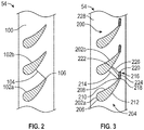
- a segment of a high pressure turbine 54 and in particular a first stage 100 which may have a plurality or cascade of similarly configured vanes, including a first vane 102a and a second vane 102b.
- a gage distance 104 is the shortest distance between a trailing edge 106 of the first vane 102a and the second vane 102b. Decreasing the gage distance 104 may provide a smaller effective flow area between the vanes 102a, 102b and may therefore provide desirable aerodynamic properties during cruise where lower turbine output is required.
- the plurality of vanes which may include a first vane 202a and a second vane 202b.
- the second vane 202b is circumferentially adjacent to a pressure side of the first vane 202a.
- the first vane 202a may have a primary vane body 204.
- the primary body 204 may have a primary airfoil.
- the primary airfoil may include a primary leading edge 206, a primary trailing edge 208, a primary pressure side 210 and a primary suction side 212.
- a primary gage distance 214 may be the shortest distance between the primary trailing edge 208 and the second vane 202b.
- a secondary vane body 216 may have a secondary leading edge 218, a secondary trailing edge 220, a secondary pressure side 222 and a secondary suction side 224.
- the secondary leading edge 218 of the secondary body 216 may be provided without an airfoil leading edge shape because the secondary leading edge 218 may be disposed internally within the primary body 204 throughout its operating life.
- a secondary gage distance 226 may be the shortest distance between the secondary trailing edge 220 and the second vane 202b.
- the span of the secondary body 216 between the stage inner diameter platform 228 and the stage outer diameter platform may be the same as for the primary body 204.
- the primary body 204 may be fixedly disposed on the turbine stage 200.
- the secondary body 216 may be in a first position which is a stowed position, wherein the radially outer surface 229 of the secondary body 216 is disposed radially flush with the platform 228.
- the secondary body 216 may also be in a second position illustrated in FIG. 6 which is the deployed configuration, wherein the secondary body extends from the inner platform to the outer platform to form a vane trailing edge extension.
- FIG. 5 illustrates a semi-deployed position of the secondary body 216.
- the secondary gage distance 226 is obtained, which is used, for example, with cruise conditions.
- the secondary gage distance 226 may be smaller than the primary gage distance 214 illustrated in FIG. 4 which is used, for example, with takeoff flow conditions.
- Typical mechanisms such as solenoids or linkages (not illustrated) may be suitable for sliding deployment of the secondary body 216. It is within the scope of the disclosure to extend secondary bodies of different vanes in a cascade on one or a plurality of stages at mutually different rates and to mutually different lengths depending on decisions made by a Full Array Digital Engine Controller, or FADEC 80 ( FIG. 1 ).
- a primary vane trailing edge slot or cutback 230 is illustrated for receiving the secondary leading edge 218 of the secondary body 216.
- the cutback 230 can have a leading edge 232 with a profile that is complementary to the secondary leading edge 218 of the secondary body 216.
- the profile of the cutback 230 has a squared leading edge 232.
- the secondary leading edge 218 of the secondary body 216 functions as a first mechanical boss for maintaining proper positioning of the secondary body 216 and to provide for smooth aerodynamic flow over the suction and pressure side surfaces of the vane.
- cooling of the secondary body 216 may be accomplished by utilizing a primary trailing edge flow 240 emerging from the cutback 230 in the primary body 204.
- Such flow 240 may be generated by the primary vane cooling air supply which is fed to the vane from either or both vane platforms (not shown) and which exits from an interior cooling passage 260 ( FIG. 9 ) incorporated in the primary vane 204 which terminates in a radially-oriented slot 262 ( FIG. 12 ) extending across most of the span of the trailing edge 208.
- film cooling holes 242 on the primary suction side 212 and/or the primary pressure side may be another outlet for cooling air fed to the vane.
- the tabs 248 Downstream of the radial slot 232 in the cutback 230 air passes around and between a plurality of aerodynamic tabs 248. Illustrated in FIG. 6 , the tabs 248 have a teardrop shape, with a bulbous side at the leading edge 249 of the tabs and a tapered side 251 at the trailing edge of the tabs 248.
- the tabs 248 may be radially spaced in the secondary body 216 and form structural supports for pressure side 222 and suction side 224 surfaces of the secondary body 216.
- the tabs extend forward of the pressure and suction side surfaces of the secondary body 216 and fit into the cutback 230.
- the plurality of tabs 248 serve as a first mechanical boss for positioning the secondary body 216 against the primary body 204. Downstream of the trailing edge of the tabs 248 airflow inside the secondary body 216 converges into a trailing edge cavity 254 in the secondary body 216 and exits via a plurality of film cooling holes 244.
- the film cooling holes may be on either or both of the suction side 222 or pressure side 224 of the secondary body 216.
- the plurality of tabs 248 form radially inner 250 and outer 229 surfaces of the secondary body 216.
- a plurality of radially extending hemispherical protrusions or bumps 252 as illustrated in FIG. 8 extend and fit into radial film cooling holes or, alternatively, into surface depressions which conform to the shape of the hemispherical protrusions on the second platform end wall (not show).
- the protrusions 252 function as second mechanical boss for locking the secondary body 216 against the second platform.
- pin type heat transfer fins 246 may be disposed within the interior cooling passage 260 ( FIG. 9 ) incorporated in the primary vane 204. Such pin fins 246 may also be incorporated between the secondary pressure side surface 222 and secondary suction side surface 224 (not shown). Such fins 246 may assist in cooling of the secondary body 216 and may provide structural support to the secondary body.
- FIGS. 9-11 illustrate additional arrangements for cooling the secondary vane body 216.
- the mating configuration between the primary trailing edge 208 and the secondary leading edge 218 are schematically illustrated. It is to be appreciated that a cutback may be utilized as with the prior embodiment, but other structural mating configurations are envisaged.
- FIG. 9 illustrates a thru passage 264 in the secondary body 216 through which cooling air exits the vane 202a.
- FIG. 12 illustrates a perspective view of the same configuration, where the trailing edge slot 262 is illustrated and the secondary body 216 is stowed.
- FIG. 13 the same configuration is illustrated in which the secondary vane body 216 is deployed.
- Trailing edge flow 240 is illustrating exiting the secondary trailing edge 218 via the thru slot 264.
- FIG. 10 illustrates a thru passage 266 that extends partially thru the secondary body 216. Cooling holes 268 may be provided in the pressure side of the secondary body 216 as well as cooling holes 270 in the suction side of the secondary body 216.
- FIG. 11 illustrates a cutback 230 where the secondary vane body 216 does not have an internal cooling channel but rather cooling air flows over the secondary pressure side surface 222 for cooling purposes.
- variable vane technology disclosed herein is not intended to limit the application of the variable vane technology disclosed herein to a high pressure turbine.
- variable vane technology disclosed herein is also applicable to, for example a low pressure turbine inlet vane.
Landscapes
- Engineering & Computer Science (AREA)
- Mechanical Engineering (AREA)
- General Engineering & Computer Science (AREA)
- Physics & Mathematics (AREA)
- Fluid Mechanics (AREA)
- Geometry (AREA)
- Turbine Rotor Nozzle Sealing (AREA)
Claims (11)
- Schaufelstufe (200) für eine Turbine (54) mit variablem Bereich, umfassend:eine Vielzahl von Schaufelplattformen, umfassend eine erste Schaufelplattform (228) und eine zweite Schaufelplattform, wobei eine der Vielzahl von Schaufelplattformen eine radial innere Schaufelplattform (228) ist und eine andere der Vielzahl von Schaufelplattformen eine radial äußere Schaufelplattform ist, und einen Raum dazwischen, der einen Luftströmungsweg definiert;einen primären Schaufelkörper (204), der an gegenüberliegenden radialen Enden der ersten Schaufelplattform (228) und der zweiten Schaufelplattform gesichert ist, wobei der primäre Schaufelkörper (204) eine primäre Vorderkante (206), eine primäre Hinterkante (208), eine primäre Druckseite (210) und eine primäre Ansaugseite (212) aufweist,einen sekundären Schaufelkörper (216), der beweglich an der ersten Schaufelplattform (228) gesichert ist, wobei der sekundäre Schaufelkörper (216) eine sekundäre Vorderkante (218), eine sekundäre Hinterkante (220), eine sekundäre Druckseite (222) und eine sekundäre Ansaugseite (224) aufweist, undwobei der sekundäre Schaufelkörper (216) zwischen einer verstauten Position, wobei sich der sekundäre Schaufelkörper außerhalb des Luftströmungswegs befindet, und einer ausgefahrenen Position bewegt werden kann, wobei sich der sekundäre Schaufelkörper zwischen der Vielzahl von Schaufelplattformen erstreckt, um eine Verlängerung einer Schaufelhinterkante auszubilden;dadurch gekennzeichnet, dass:der sekundäre Schaufelkörper (216) eine Vielzahl von radial beabstandeten Laschen (248) beinhaltet, welche die sekundäre Druckseite (222) und die sekundäre Ansaugseite (224) des sekundären Körpers (216) stützt, wobei die Vielzahl von Laschen (248) die Vorderkante (218) des sekundären Schaufelkörpers (216) definiert und die Laschen (248) eine erste Auswölbung zum Positionieren des sekundären Schaufelkörpers (216) an der Hinterkante (208) des primären Schaufelkörpers (204) ausbilden; undeine Hinterkante (251) der Vielzahl von Laschen (248) konisch ist, um einen Luftkonvergenzhohlraum (254) innerhalb des sekundären Schaufelkörpers (216) auszubilden, und wobei der Luftkonvergenzhohlraum (254) Luft (240) aufnimmt, die von der Hinterkante (208) des primären Schaufelkörpers (204) strömt, wenn sich der sekundäre Schaufelkörper (216) in der ausgefahrenen Position befindet.
- Schaufelstufe (200) nach Anspruch 1, wobei in der verstauten Position eine erste radiale Endfläche (229) des sekundären Schaufelkörpers (216) bündig mit der ersten Schaufelplattform (228) ist.
- Schaufelstufe (200) nach Anspruch 1, wobei die radiale Endfläche (229) des sekundären Schaufelkörpers (216) eine Vielzahl von Vorsprüngen (252) beinhaltet, die eine zweite Auswölbung zum Positionieren des sekundären Schaufelkörpers (216) gegen die zweite Schaufelplattform ausbildet.
- Schaufelstufe (200) nach Anspruch 1 oder 3, wobei die Hinterkante (208) des primären Körpers (204) einen Kühlluftschlitz (262) beinhaltet.
- Schaufelstufe (200) nach Anspruch 1, wobei der sekundäre Schaufelkörper (216) eine Vielzahl von Kühllöchern (244; 268, 270) in einer oder beiden der sekundären Druckseitenfläche (222) und der sekundären Ansaugseitenfläche (224) in der Nähe des Luftkonvergenzhohlraums (254) beinhaltet.
- Schaufelstufe (200) nach einem beliebigen vorhergehenden Anspruch, wobei der sekundäre Schaufelkörper (216) einen Kühlschlitz beinhaltet, der sich von der Vorderkante (218) zu der Hinterkante (220) des sekundären Körpers (216) erstreckt.
- Schaufelstufe (200) nach einem beliebigen vorhergehenden Anspruch, wobei die Hinterkante (208) des primären Schaufelkörpers (204) einen sich radial erstreckenden zurückgeschnittenen Schlitz (230) beinhaltet, entlang von welchem die sekundäre Vorderkante (218) des sekundären Schaufelkörpers (216) in der ausgefahrenen Position positioniert ist.
- Gasturbinentriebwerk (20), umfassend:
eine Turbine (54) mit variablem Bereich, die eine Schaufelstufe (200) nach einem beliebigen vorhergehenden Anspruch beinhaltet. - Triebwerk nach Anspruch 8, wobei der sekundäre Schaufelkörper (216) eine Vielzahl von radial beabstandeten Laschen (248) beinhaltet, welche die sekundäre Druckseite (222) und die sekundäre Ansaugseite (224) des sekundären Körpers (216) stützt, wobei die Vielzahl von Laschen (248) die Vorderkante (218) des sekundären Schaufelkörpers (216) definiert und die Laschen (248) eine erste Auswölbung zum Positionieren des sekundären Schaufelkörpers (216) an der Hinterkante (208) des primären Schaufelkörpers (204) ausbilden, und wobei eine Hinterkante der Vielzahl von Laschen (248) konisch ist, um einen Luftkonvergenzhohlraum (254) innerhalb der Hinterkante (220) des sekundären Schaufelkörpers (216) auszubilden, und wobei der Luftkonvergenzhohlraum (254) Luft aufnimmt, die von einer Vielzahl von Folienkühllöchern strömt, wenn sich der sekundäre Schaufelkörper (216) in der ausgefahrenen Position befindet.
- Triebwerk nach Anspruch 9, wobei der sekundäre Schaufelkörper (216) eine Vielzahl von Kühllöchern (244; 268, 270) in einer oder beiden der sekundären Druckseitenfläche (222) und der sekundären Ansaugseitenfläche (224) in der Nähe des Luftkonvergenzhohlraums (254) beinhaltet.
- Verfahren zum Verringern eines Maßabstands zwischen mindestens zwei Schaufeln (202a, 202b) in einer Vielzahl von Schaufeln an einer ersten Stufe (200) einer Turbine mit variablem Bereich, wobei die mindestens zwei Schaufeln (202a, 202b) eine erste Schaufel (202a) und eine zweite Schaufel (202b) sind, wobei:die erste Stufe eine Vielzahl von Schaufelplattformen beinhaltet, umfassend eine erste Schaufelplattform (228) und eine zweite Schaufelplattform, wobei eine der Vielzahl von Schaufelplattformen eine radial innere Schaufelplattform (228) ist und eine andere der Vielzahl von Schaufelplattformen eine radial äußere Schaufelplattform ist, und einen Raum dazwischen, der einen Luftströmungsweg definiert;die erste Schaufel (202a) einen primären Schaufelkörper (204) beinhaltet, der an gegenüberliegenden radialen Enden der ersten Schaufelplattform (228) und der zweiten Schaufelplattform gesichert ist, wobei der primäre Schaufelkörper (204) eine primäre Vorderkante (206), eine primäre Hinterkante (208), eine primäre Druckseite (210) und eine primäre Ansaugseite (212) aufweist,die zweite Schaufel (202b) einen sekundären Schaufelkörper (216) beinhaltet, der beweglich an der ersten Schaufelplattform (228) gesichert ist, wobei der sekundäre Schaufelkörper (216) eine sekundäre Vorderkante (218), eine sekundäre Hinterkante (220), eine sekundäre Druckseite (222) und eine sekundäre Ansaugseite (224) aufweist, undwobei der sekundäre Schaufelkörper (216) zwischen einer verstauten Position, wobei sich der sekundäre Schaufelkörper außerhalb des Luftströmungswegs befindet, und einer ausgefahrenen Position bewegt werden kann, wobei sich der sekundäre Schaufelkörper zwischen der Vielzahl von Schaufelplattformen erstreckt, um eine Verlängerung einer Schaufelhinterkante auszubilden;
wobei:der sekundäre Schaufelkörper (216) eine Vielzahl von radial beabstandeten Laschen (248) beinhaltet, welche die sekundäre Druckseite (222) und die sekundäre Ansaugseite (224) des sekundären Körpers (216) stützt, wobei die Vielzahl von Laschen (248) die Vorderkante (218) des sekundären Schaufelkörpers (216) definiert und die Laschen (248) eine erste Auswölbung zum Positionieren des sekundären Schaufelkörpers (216) an der Hinterkante (208) des primären Schaufelkörpers (204) ausbilden; undeine Hinterkante (251) der Vielzahl von Laschen (248) konisch ist, um einen Luftkonvergenzhohlraum (254) innerhalb des sekundären Schaufelkörpers (216) auszubilden, und wobei der Luftkonvergenzhohlraum (254) Luft (240) aufnimmt, die von der Hinterkante (208) des primären Schaufelkörpers (204) strömt, wenn sich der sekundäre Schaufelkörper (216) in der ausgefahrenen Position befindet;wobei das Verfahren Ausfahren des verstauten Schaufelkörpers (216) von unterhalb der Schaufelplattform (228) von mindestens einer der mindestens zwei Schaufeln (202a, 202b) umfasst.
Applications Claiming Priority (1)
| Application Number | Priority Date | Filing Date | Title |
|---|---|---|---|
| US15/701,008 US10480326B2 (en) | 2017-09-11 | 2017-09-11 | Vane for variable area turbine |
Publications (2)
| Publication Number | Publication Date |
|---|---|
| EP3453830A1 EP3453830A1 (de) | 2019-03-13 |
| EP3453830B1 true EP3453830B1 (de) | 2020-05-13 |
Family
ID=63557367
Family Applications (1)
| Application Number | Title | Priority Date | Filing Date |
|---|---|---|---|
| EP18193858.0A Active EP3453830B1 (de) | 2017-09-11 | 2018-09-11 | Turbinenleitschaufelanordnung mit variablem bereich |
Country Status (2)
| Country | Link |
|---|---|
| US (1) | US10480326B2 (de) |
| EP (1) | EP3453830B1 (de) |
Families Citing this family (3)
| Publication number | Priority date | Publication date | Assignee | Title |
|---|---|---|---|---|
| US20180216527A1 (en) * | 2017-01-27 | 2018-08-02 | General Electric Company | Radial variable inlet guide vane for axial or axi-centrifugal compressors |
| US10934883B2 (en) * | 2018-09-12 | 2021-03-02 | Raytheon Technologies | Cover for airfoil assembly for a gas turbine engine |
| CN113819487B (zh) * | 2021-08-17 | 2024-09-20 | 南京航空航天大学 | 进气余旋角度和温度分布耦合的瞬态可调畸变发生装置 |
Family Cites Families (19)
| Publication number | Priority date | Publication date | Assignee | Title |
|---|---|---|---|---|
| US3563669A (en) | 1969-07-10 | 1971-02-16 | Gen Motors Corp | Variable area nozzle |
| FR2586268B1 (fr) * | 1985-08-14 | 1989-06-09 | Snecma | Dispositif de variation de la section de passage d'un distributeur de turbine |
| GB2218746B (en) * | 1988-05-17 | 1992-06-17 | Rolls Royce Plc | A nozzle guide vane for a gas turbine engine |
| US5683225A (en) | 1991-10-28 | 1997-11-04 | General Electric Company | Jet engine variable area turbine nozzle |
| GB9203168D0 (en) * | 1992-02-13 | 1992-04-01 | Rolls Royce Plc | Guide vanes for gas turbine engines |
| FR2714109B1 (fr) * | 1993-12-22 | 1996-01-19 | Snecma | Aube de turbomachine à cambrure variable. |
| US5931636A (en) * | 1997-08-28 | 1999-08-03 | General Electric Company | Variable area turbine nozzle |
| US6139268A (en) * | 1999-03-19 | 2000-10-31 | The United States Of America As Represented By The Secretary Of The Air Force | Turbine blade having an extensible tail |
| US6419464B1 (en) * | 2001-01-16 | 2002-07-16 | Honeywell International Inc. | Vane for variable nozzle turbocharger |
| US6681558B2 (en) * | 2001-03-26 | 2004-01-27 | General Electric Company | Method of increasing engine temperature limit margins |
| US6966755B2 (en) * | 2004-02-09 | 2005-11-22 | Siemens Westinghouse Power Corporation | Compressor airfoils with movable tips |
| US7828523B2 (en) * | 2007-03-27 | 2010-11-09 | General Electric Company | Rotor blade for a wind turbine having a variable dimension |
| US8459035B2 (en) | 2007-07-27 | 2013-06-11 | United Technologies Corporation | Gas turbine engine with low fan pressure ratio |
| US8052388B2 (en) * | 2007-11-29 | 2011-11-08 | United Technologies Corporation | Gas turbine engine systems involving mechanically alterable vane throat areas |
| US9328617B2 (en) * | 2012-03-20 | 2016-05-03 | United Technologies Corporation | Trailing edge or tip flag antiflow separation |
| US9109452B2 (en) * | 2012-06-05 | 2015-08-18 | United Technologies Corporation | Vortex generators for improved film effectiveness |
| US9840934B2 (en) | 2013-12-11 | 2017-12-12 | United Technologies Corporation | Aero-actuated vanes |
| EP2905425B1 (de) | 2014-02-06 | 2019-07-10 | United Technologies Corporation | Verstellbare schaufel und dichtungsanordnung |
| US10253648B2 (en) * | 2016-03-04 | 2019-04-09 | General Electric Company | Modulated hybrid variable area turbine nozzle for gas turbine engine |
-
2017
- 2017-09-11 US US15/701,008 patent/US10480326B2/en active Active
-
2018
- 2018-09-11 EP EP18193858.0A patent/EP3453830B1/de active Active
Non-Patent Citations (1)
| Title |
|---|
| None * |
Also Published As
| Publication number | Publication date |
|---|---|
| US20190078440A1 (en) | 2019-03-14 |
| US10480326B2 (en) | 2019-11-19 |
| EP3453830A1 (de) | 2019-03-13 |
Similar Documents
| Publication | Publication Date | Title |
|---|---|---|
| EP2977555B1 (de) | Schaufelplattform mit kühlkanäle | |
| EP3091186B1 (de) | Turbinenmotorkomponente mit einem durch einen absatz unterbrochenen axial ausgerichteten verkleidungskernkanal | |
| US11085305B2 (en) | Lost core structural frame | |
| US20180023407A1 (en) | Gas turbine engine turbine vane baffle and serpentine cooling passage | |
| EP3453830B1 (de) | Turbinenleitschaufelanordnung mit variablem bereich | |
| EP3266983A1 (de) | Kühlsystem für eine schaufel einer gasbetriebenen turbine | |
| EP3112596A1 (de) | Gasturbinenmotorschaufel mit biaxialem wandkühlkanal und zugehöriger gasturbinenmotor | |
| EP3045666B1 (de) | Tragflächenplattform mit kühlungseinspeisungsöffnungen | |
| US10968753B1 (en) | Airfoil having impingement leading edge | |
| US10801333B2 (en) | Airfoils, cores, and methods of manufacture for forming airfoils having fluidly connected platform cooling circuits | |
| US11028700B2 (en) | Airfoil with cooling passage circuit through platforms and airfoil section | |
| US20160326909A1 (en) | Gas turbine engine component with separation rib for cooling passages | |
| EP3693544A1 (de) | Tangentialeinspritzdüse einer gasturbine mit durchgehender umlenkdüse | |
| EP3907373B1 (de) | Kühllochkombination für turbinenschaufel | |
| EP3667030B1 (de) | Modulare variable leitschaufelanordnung für einen verdichterabschnitt eines gasturbinentriebwerks | |
| EP3581762B1 (de) | Kühlkanalanordnung für gasturbinendeckband | |
| EP3453833B1 (de) | Turbinenschaufel und zugehöriges gasturbinentriebwerk | |
| EP3502417B1 (de) | Ströumungsumlenkelemente einer plattform für gasturbinenmotorkomponenten |
Legal Events
| Date | Code | Title | Description |
|---|---|---|---|
| PUAI | Public reference made under article 153(3) epc to a published international application that has entered the european phase |
Free format text: ORIGINAL CODE: 0009012 |
|
| STAA | Information on the status of an ep patent application or granted ep patent |
Free format text: STATUS: THE APPLICATION HAS BEEN PUBLISHED |
|
| AK | Designated contracting states |
Kind code of ref document: A1 Designated state(s): AL AT BE BG CH CY CZ DE DK EE ES FI FR GB GR HR HU IE IS IT LI LT LU LV MC MK MT NL NO PL PT RO RS SE SI SK SM TR |
|
| AX | Request for extension of the european patent |
Extension state: BA ME |
|
| STAA | Information on the status of an ep patent application or granted ep patent |
Free format text: STATUS: REQUEST FOR EXAMINATION WAS MADE |
|
| 17P | Request for examination filed |
Effective date: 20190913 |
|
| RBV | Designated contracting states (corrected) |
Designated state(s): AL AT BE BG CH CY CZ DE DK EE ES FI FR GB GR HR HU IE IS IT LI LT LU LV MC MK MT NL NO PL PT RO RS SE SI SK SM TR |
|
| GRAP | Despatch of communication of intention to grant a patent |
Free format text: ORIGINAL CODE: EPIDOSNIGR1 |
|
| STAA | Information on the status of an ep patent application or granted ep patent |
Free format text: STATUS: GRANT OF PATENT IS INTENDED |
|
| INTG | Intention to grant announced |
Effective date: 20191127 |
|
| GRAS | Grant fee paid |
Free format text: ORIGINAL CODE: EPIDOSNIGR3 |
|
| GRAA | (expected) grant |
Free format text: ORIGINAL CODE: 0009210 |
|
| STAA | Information on the status of an ep patent application or granted ep patent |
Free format text: STATUS: THE PATENT HAS BEEN GRANTED |
|
| AK | Designated contracting states |
Kind code of ref document: B1 Designated state(s): AL AT BE BG CH CY CZ DE DK EE ES FI FR GB GR HR HU IE IS IT LI LT LU LV MC MK MT NL NO PL PT RO RS SE SI SK SM TR |
|
| REG | Reference to a national code |
Ref country code: GB Ref legal event code: FG4D |
|
| REG | Reference to a national code |
Ref country code: CH Ref legal event code: EP |
|
| REG | Reference to a national code |
Ref country code: DE Ref legal event code: R096 Ref document number: 602018004527 Country of ref document: DE |
|
| REG | Reference to a national code |
Ref country code: AT Ref legal event code: REF Ref document number: 1270533 Country of ref document: AT Kind code of ref document: T Effective date: 20200615 |
|
| REG | Reference to a national code |
Ref country code: LT Ref legal event code: MG4D |
|
| REG | Reference to a national code |
Ref country code: NL Ref legal event code: MP Effective date: 20200513 |
|
| PG25 | Lapsed in a contracting state [announced via postgrant information from national office to epo] |
Ref country code: SE Free format text: LAPSE BECAUSE OF FAILURE TO SUBMIT A TRANSLATION OF THE DESCRIPTION OR TO PAY THE FEE WITHIN THE PRESCRIBED TIME-LIMIT Effective date: 20200513 Ref country code: LT Free format text: LAPSE BECAUSE OF FAILURE TO SUBMIT A TRANSLATION OF THE DESCRIPTION OR TO PAY THE FEE WITHIN THE PRESCRIBED TIME-LIMIT Effective date: 20200513 Ref country code: PT Free format text: LAPSE BECAUSE OF FAILURE TO SUBMIT A TRANSLATION OF THE DESCRIPTION OR TO PAY THE FEE WITHIN THE PRESCRIBED TIME-LIMIT Effective date: 20200914 Ref country code: IS Free format text: LAPSE BECAUSE OF FAILURE TO SUBMIT A TRANSLATION OF THE DESCRIPTION OR TO PAY THE FEE WITHIN THE PRESCRIBED TIME-LIMIT Effective date: 20200913 Ref country code: GR Free format text: LAPSE BECAUSE OF FAILURE TO SUBMIT A TRANSLATION OF THE DESCRIPTION OR TO PAY THE FEE WITHIN THE PRESCRIBED TIME-LIMIT Effective date: 20200814 Ref country code: NO Free format text: LAPSE BECAUSE OF FAILURE TO SUBMIT A TRANSLATION OF THE DESCRIPTION OR TO PAY THE FEE WITHIN THE PRESCRIBED TIME-LIMIT Effective date: 20200813 Ref country code: FI Free format text: LAPSE BECAUSE OF FAILURE TO SUBMIT A TRANSLATION OF THE DESCRIPTION OR TO PAY THE FEE WITHIN THE PRESCRIBED TIME-LIMIT Effective date: 20200513 |
|
| PG25 | Lapsed in a contracting state [announced via postgrant information from national office to epo] |
Ref country code: LV Free format text: LAPSE BECAUSE OF FAILURE TO SUBMIT A TRANSLATION OF THE DESCRIPTION OR TO PAY THE FEE WITHIN THE PRESCRIBED TIME-LIMIT Effective date: 20200513 Ref country code: HR Free format text: LAPSE BECAUSE OF FAILURE TO SUBMIT A TRANSLATION OF THE DESCRIPTION OR TO PAY THE FEE WITHIN THE PRESCRIBED TIME-LIMIT Effective date: 20200513 Ref country code: BG Free format text: LAPSE BECAUSE OF FAILURE TO SUBMIT A TRANSLATION OF THE DESCRIPTION OR TO PAY THE FEE WITHIN THE PRESCRIBED TIME-LIMIT Effective date: 20200813 Ref country code: RS Free format text: LAPSE BECAUSE OF FAILURE TO SUBMIT A TRANSLATION OF THE DESCRIPTION OR TO PAY THE FEE WITHIN THE PRESCRIBED TIME-LIMIT Effective date: 20200513 |
|
| REG | Reference to a national code |
Ref country code: AT Ref legal event code: MK05 Ref document number: 1270533 Country of ref document: AT Kind code of ref document: T Effective date: 20200513 |
|
| PG25 | Lapsed in a contracting state [announced via postgrant information from national office to epo] |
Ref country code: NL Free format text: LAPSE BECAUSE OF FAILURE TO SUBMIT A TRANSLATION OF THE DESCRIPTION OR TO PAY THE FEE WITHIN THE PRESCRIBED TIME-LIMIT Effective date: 20200513 Ref country code: AL Free format text: LAPSE BECAUSE OF FAILURE TO SUBMIT A TRANSLATION OF THE DESCRIPTION OR TO PAY THE FEE WITHIN THE PRESCRIBED TIME-LIMIT Effective date: 20200513 |
|
| PG25 | Lapsed in a contracting state [announced via postgrant information from national office to epo] |
Ref country code: RO Free format text: LAPSE BECAUSE OF FAILURE TO SUBMIT A TRANSLATION OF THE DESCRIPTION OR TO PAY THE FEE WITHIN THE PRESCRIBED TIME-LIMIT Effective date: 20200513 Ref country code: IT Free format text: LAPSE BECAUSE OF FAILURE TO SUBMIT A TRANSLATION OF THE DESCRIPTION OR TO PAY THE FEE WITHIN THE PRESCRIBED TIME-LIMIT Effective date: 20200513 Ref country code: CZ Free format text: LAPSE BECAUSE OF FAILURE TO SUBMIT A TRANSLATION OF THE DESCRIPTION OR TO PAY THE FEE WITHIN THE PRESCRIBED TIME-LIMIT Effective date: 20200513 Ref country code: ES Free format text: LAPSE BECAUSE OF FAILURE TO SUBMIT A TRANSLATION OF THE DESCRIPTION OR TO PAY THE FEE WITHIN THE PRESCRIBED TIME-LIMIT Effective date: 20200513 Ref country code: AT Free format text: LAPSE BECAUSE OF FAILURE TO SUBMIT A TRANSLATION OF THE DESCRIPTION OR TO PAY THE FEE WITHIN THE PRESCRIBED TIME-LIMIT Effective date: 20200513 Ref country code: SM Free format text: LAPSE BECAUSE OF FAILURE TO SUBMIT A TRANSLATION OF THE DESCRIPTION OR TO PAY THE FEE WITHIN THE PRESCRIBED TIME-LIMIT Effective date: 20200513 Ref country code: EE Free format text: LAPSE BECAUSE OF FAILURE TO SUBMIT A TRANSLATION OF THE DESCRIPTION OR TO PAY THE FEE WITHIN THE PRESCRIBED TIME-LIMIT Effective date: 20200513 Ref country code: DK Free format text: LAPSE BECAUSE OF FAILURE TO SUBMIT A TRANSLATION OF THE DESCRIPTION OR TO PAY THE FEE WITHIN THE PRESCRIBED TIME-LIMIT Effective date: 20200513 |
|
| REG | Reference to a national code |
Ref country code: DE Ref legal event code: R097 Ref document number: 602018004527 Country of ref document: DE |
|
| PG25 | Lapsed in a contracting state [announced via postgrant information from national office to epo] |
Ref country code: SK Free format text: LAPSE BECAUSE OF FAILURE TO SUBMIT A TRANSLATION OF THE DESCRIPTION OR TO PAY THE FEE WITHIN THE PRESCRIBED TIME-LIMIT Effective date: 20200513 Ref country code: PL Free format text: LAPSE BECAUSE OF FAILURE TO SUBMIT A TRANSLATION OF THE DESCRIPTION OR TO PAY THE FEE WITHIN THE PRESCRIBED TIME-LIMIT Effective date: 20200513 |
|
| PLBE | No opposition filed within time limit |
Free format text: ORIGINAL CODE: 0009261 |
|
| STAA | Information on the status of an ep patent application or granted ep patent |
Free format text: STATUS: NO OPPOSITION FILED WITHIN TIME LIMIT |
|
| RAP2 | Party data changed (patent owner data changed or rights of a patent transferred) |
Owner name: RAYTHEON TECHNOLOGIES CORPORATION |
|
| 26N | No opposition filed |
Effective date: 20210216 |
|
| PG25 | Lapsed in a contracting state [announced via postgrant information from national office to epo] |
Ref country code: SI Free format text: LAPSE BECAUSE OF FAILURE TO SUBMIT A TRANSLATION OF THE DESCRIPTION OR TO PAY THE FEE WITHIN THE PRESCRIBED TIME-LIMIT Effective date: 20200513 |
|
| REG | Reference to a national code |
Ref country code: BE Ref legal event code: MM Effective date: 20200930 |
|
| PG25 | Lapsed in a contracting state [announced via postgrant information from national office to epo] |
Ref country code: LU Free format text: LAPSE BECAUSE OF NON-PAYMENT OF DUE FEES Effective date: 20200911 |
|
| PG25 | Lapsed in a contracting state [announced via postgrant information from national office to epo] |
Ref country code: BE Free format text: LAPSE BECAUSE OF NON-PAYMENT OF DUE FEES Effective date: 20200930 Ref country code: IE Free format text: LAPSE BECAUSE OF NON-PAYMENT OF DUE FEES Effective date: 20200911 |
|
| REG | Reference to a national code |
Ref country code: CH Ref legal event code: PL |
|
| PG25 | Lapsed in a contracting state [announced via postgrant information from national office to epo] |
Ref country code: TR Free format text: LAPSE BECAUSE OF FAILURE TO SUBMIT A TRANSLATION OF THE DESCRIPTION OR TO PAY THE FEE WITHIN THE PRESCRIBED TIME-LIMIT Effective date: 20200513 Ref country code: MT Free format text: LAPSE BECAUSE OF FAILURE TO SUBMIT A TRANSLATION OF THE DESCRIPTION OR TO PAY THE FEE WITHIN THE PRESCRIBED TIME-LIMIT Effective date: 20200513 Ref country code: CY Free format text: LAPSE BECAUSE OF FAILURE TO SUBMIT A TRANSLATION OF THE DESCRIPTION OR TO PAY THE FEE WITHIN THE PRESCRIBED TIME-LIMIT Effective date: 20200513 |
|
| PG25 | Lapsed in a contracting state [announced via postgrant information from national office to epo] |
Ref country code: MK Free format text: LAPSE BECAUSE OF FAILURE TO SUBMIT A TRANSLATION OF THE DESCRIPTION OR TO PAY THE FEE WITHIN THE PRESCRIBED TIME-LIMIT Effective date: 20200513 Ref country code: MC Free format text: LAPSE BECAUSE OF FAILURE TO SUBMIT A TRANSLATION OF THE DESCRIPTION OR TO PAY THE FEE WITHIN THE PRESCRIBED TIME-LIMIT Effective date: 20200513 |
|
| PG25 | Lapsed in a contracting state [announced via postgrant information from national office to epo] |
Ref country code: LI Free format text: LAPSE BECAUSE OF NON-PAYMENT OF DUE FEES Effective date: 20210930 Ref country code: CH Free format text: LAPSE BECAUSE OF NON-PAYMENT OF DUE FEES Effective date: 20210930 |
|
| P01 | Opt-out of the competence of the unified patent court (upc) registered |
Effective date: 20230521 |
|
| REG | Reference to a national code |
Ref country code: DE Ref legal event code: R081 Ref document number: 602018004527 Country of ref document: DE Owner name: RTX CORPORATION (N.D.GES.D. STAATES DELAWARE),, US Free format text: FORMER OWNER: UNITED TECHNOLOGIES CORPORATION, FARMINGTON, CONN., US |
|
| PGFP | Annual fee paid to national office [announced via postgrant information from national office to epo] |
Ref country code: DE Payment date: 20250820 Year of fee payment: 8 |
|
| PGFP | Annual fee paid to national office [announced via postgrant information from national office to epo] |
Ref country code: GB Payment date: 20250822 Year of fee payment: 8 |
|
| PGFP | Annual fee paid to national office [announced via postgrant information from national office to epo] |
Ref country code: FR Payment date: 20250821 Year of fee payment: 8 |