EP3454043A1 - Dispositif de traitement d'informations, procédé de traitement d'informations, programme, et système de traitement d'informations - Google Patents
Dispositif de traitement d'informations, procédé de traitement d'informations, programme, et système de traitement d'informations Download PDFInfo
- Publication number
- EP3454043A1 EP3454043A1 EP17792632.6A EP17792632A EP3454043A1 EP 3454043 A1 EP3454043 A1 EP 3454043A1 EP 17792632 A EP17792632 A EP 17792632A EP 3454043 A1 EP3454043 A1 EP 3454043A1
- Authority
- EP
- European Patent Office
- Prior art keywords
- spectra
- group
- spectrum
- reference spectrum
- outlier
- Prior art date
- Legal status (The legal status is an assumption and is not a legal conclusion. Google has not performed a legal analysis and makes no representation as to the accuracy of the status listed.)
- Granted
Links
Images








Classifications
-
- G—PHYSICS
- G01—MEASURING; TESTING
- G01N—INVESTIGATING OR ANALYSING MATERIALS BY DETERMINING THEIR CHEMICAL OR PHYSICAL PROPERTIES
- G01N21/00—Investigating or analysing materials by the use of optical means, i.e. using sub-millimetre waves, infrared, visible or ultraviolet light
- G01N21/17—Systems in which incident light is modified in accordance with the properties of the material investigated
- G01N21/25—Colour; Spectral properties, i.e. comparison of effect of material on the light at two or more different wavelengths or wavelength bands
- G01N21/27—Colour; Spectral properties, i.e. comparison of effect of material on the light at two or more different wavelengths or wavelength bands using photo-electric detection ; circuits for computing concentration
-
- G—PHYSICS
- G01—MEASURING; TESTING
- G01N—INVESTIGATING OR ANALYSING MATERIALS BY DETERMINING THEIR CHEMICAL OR PHYSICAL PROPERTIES
- G01N15/00—Investigating characteristics of particles; Investigating permeability, pore-volume or surface-area of porous materials
- G01N15/10—Investigating individual particles
- G01N15/14—Optical investigation techniques, e.g. flow cytometry
- G01N15/1456—Optical investigation techniques, e.g. flow cytometry without spatial resolution of the texture or inner structure of the particle, e.g. processing of pulse signals
- G01N15/1459—Optical investigation techniques, e.g. flow cytometry without spatial resolution of the texture or inner structure of the particle, e.g. processing of pulse signals the analysis being performed on a sample stream
-
- G—PHYSICS
- G01—MEASURING; TESTING
- G01N—INVESTIGATING OR ANALYSING MATERIALS BY DETERMINING THEIR CHEMICAL OR PHYSICAL PROPERTIES
- G01N15/00—Investigating characteristics of particles; Investigating permeability, pore-volume or surface-area of porous materials
- G01N15/10—Investigating individual particles
- G01N15/1012—Calibrating particle analysers; References therefor
-
- G—PHYSICS
- G01—MEASURING; TESTING
- G01N—INVESTIGATING OR ANALYSING MATERIALS BY DETERMINING THEIR CHEMICAL OR PHYSICAL PROPERTIES
- G01N15/00—Investigating characteristics of particles; Investigating permeability, pore-volume or surface-area of porous materials
- G01N15/10—Investigating individual particles
- G01N15/14—Optical investigation techniques, e.g. flow cytometry
- G01N15/1429—Signal processing
-
- G—PHYSICS
- G01—MEASURING; TESTING
- G01N—INVESTIGATING OR ANALYSING MATERIALS BY DETERMINING THEIR CHEMICAL OR PHYSICAL PROPERTIES
- G01N21/00—Investigating or analysing materials by the use of optical means, i.e. using sub-millimetre waves, infrared, visible or ultraviolet light
- G01N21/17—Systems in which incident light is modified in accordance with the properties of the material investigated
-
- G—PHYSICS
- G01—MEASURING; TESTING
- G01N—INVESTIGATING OR ANALYSING MATERIALS BY DETERMINING THEIR CHEMICAL OR PHYSICAL PROPERTIES
- G01N21/00—Investigating or analysing materials by the use of optical means, i.e. using sub-millimetre waves, infrared, visible or ultraviolet light
- G01N21/62—Systems in which the material investigated is excited whereby it emits light or causes a change in wavelength of the incident light
- G01N21/63—Systems in which the material investigated is excited whereby it emits light or causes a change in wavelength of the incident light optically excited
- G01N21/64—Fluorescence; Phosphorescence
-
- G—PHYSICS
- G16—INFORMATION AND COMMUNICATION TECHNOLOGY [ICT] SPECIALLY ADAPTED FOR SPECIFIC APPLICATION FIELDS
- G16C—COMPUTATIONAL CHEMISTRY; CHEMOINFORMATICS; COMPUTATIONAL MATERIALS SCIENCE
- G16C20/00—Chemoinformatics, i.e. ICT specially adapted for the handling of physicochemical or structural data of chemical particles, elements, compounds or mixtures
- G16C20/30—Prediction of properties of chemical compounds, compositions or mixtures
-
- G—PHYSICS
- G01—MEASURING; TESTING
- G01N—INVESTIGATING OR ANALYSING MATERIALS BY DETERMINING THEIR CHEMICAL OR PHYSICAL PROPERTIES
- G01N15/00—Investigating characteristics of particles; Investigating permeability, pore-volume or surface-area of porous materials
- G01N15/10—Investigating individual particles
- G01N2015/1006—Investigating individual particles for cytology
Definitions
- the present disclosure relates to an information processing device, an information processing method, a program, and an information processing system.
- an analysis approach by means of an apparatus (such as a flow cytometer, for example) that measures the intensity, spectrum, and the like of fluorescence or scattered light emitted from the microparticles is used.
- an apparatus such as a flow cytometer, for example
- excitation light such as laser light is applied to microparticles flowing in a channel
- fluorescence, scattered light, or the like emitted from the microparticles is detected by photodetectors such as a plurality of photo multiplier tubes (PMTs).
- PMTs photo multiplier tubes
- Patent Literature 1 discloses a technology of deconvoluting spectra obtained by applying laser light to microparticles labeled using a plurality of fluorochromes by a spectrum (reference spectrum) per fluorochrome to analyze the fluorescence intensity per light-emitting element such as a fluorochrome that labels the microparticles.
- the measured spectrum can be expressed by a linear sum obtained by multiplying the reference spectrum per light-emitting element by a predetermined coefficient. Accordingly, the fluorescence intensity of each fluorochrome that labels the microparticles can be calculated.
- Patent Literature 1 JP 2013-24792A
- the accuracy of the reference spectrum for use in the above-described deconvolution is sufficiently high. Since the shape of fluorescence spectra acquired from microparticles affects a measurement environment, the above-described reference spectrum is usually generated on the basis of spectra obtained from microparticles simply stained with one fluorochrome (or unstained) in an environment identical to the measurement environment. However, depending on the measurement environment or microparticles, many noises or abnormal values may be included in the generated reference spectrum. When noises or abnormal values are included in the reference spectrum, the accuracy of the reference spectrum is reduced, and thus, the calculation accuracy of the fluorescence intensity per light-emitting element calculated using the reference spectrum can be reduced.
- the present disclosure proposes an information processing device, an information processing method, a program, and an information processing system being novel and improved that can increase the accuracy of a reference spectrum.
- an information processing device including: a statistical processing unit configured to perform statistical processing for a group of spectra obtained by applying light to a group of microparticles that exhibit one response property with respect to light, and on a basis of a result of the statistical processing, exclude a spectrum indicating an outlier from the group of spectra; and a reference spectrum calculation unit configured to calculate a reference spectrum using the group of spectra from which the spectrum indicating the outlier has been excluded.
- an information processing method including, by a processor: performing statistical processing for a group of spectra obtained by applying light to a group of microparticles that exhibit one response property with respect to light, and on a basis of a result of the statistical processing, excluding a spectrum indicating an outlier from the group of spectra; and calculating a reference spectrum using at least one group of spectra from which the spectrum indicating the outlier has been excluded.
- an information processing system including: a measurement device including a measurement unit configured to apply light to a measurement target to measure a spectrum related to light emission of the measurement target; and an information processing device including an information processing device including a statistical processing unit configured to perform statistical processing for a group of spectra related to a group of microparticles that exhibit one response property with respect to light, obtained from the measurement unit, and on a basis of a result of the statistical processing, exclude a spectrum indicating an outlier from the group of spectra, and a reference spectrum calculation unit configured to calculate a reference spectrum using at least one group of spectra from which the spectrum indicating the outlier has been excluded.
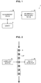
- FIG. 1 is a diagram showing a schematic configuration of an information processing system 1 according to one embodiment of the present disclosure.
- the information processing system 1 includes an information processing device 10 and a measurement device 20 that measures a spectrum corresponding to a sample S.
- the information processing device 10 and the measurement device 20 are connected with wired or wireless various networks.
- a bio-related microparticle such as a cell, a microorganism, or a liposome, a synthetic particle such as a latex particle, a gel particle, an industrial particle, or a microbead, or the like, for example, can be utilized.
- the bio-related microparticle includes chromosomes, liposomes, mitochondria, organelles, and the like included in various cells.
- the cell includes animal cells (such as haematopoietic cells) and plant cells.
- the microorganism includes bacteria such as Escherichia coli, viruses such as tobacco mosaic virus, fungi such as yeast cells, and the like.
- the bio-related microparticle may include bio-related polymers such as nucleic acid, proteins such as enzyme, their composites, and the like.
- the industrial particle may be an organic polymer material, an inorganic polymer material, metal, or the like, for example.
- the organic polymer material includes polystyrene, styrene-divinylbenzene, polymethylmethacrylate, and the like.
- the inorganic polymer material includes glass, silica, magnetic substance materials, and the like.
- the metal includes noble metal colloid, aluminum, and the like.
- the shape of these microparticles is mainly spherical, but may be non-spherical.
- the size, mass, and the like of the microparticles are not particularly limited.
- the information processing device 10 acquires measured data of the sample S measured by the measurement device 20, separates (deconvolutes) a spectrum which is the acquired measured data into a plurality of spectra, and analyzes the intensity of each of the separated spectra. For example, the information processing device 10 separates an acquired fluorescence spectrum of the sample S into fluorescence spectra derived from a plurality of fluorochromes that label the sample S, and analyzes the amount of fluorescence of each of the separated fluorescence spectra. On the basis of this amount of fluorescence, properties that labeled microparticles have can be analyzed.
- FIG. 1 illustrates the case where the information processing device 10 according to the present embodiment is provided as a device different from the measurement device 20, whilst the functions of the information processing device 10 according to the present embodiment may be mounted on a computer that controls the operation of the measurement device 20, or may be mounted on any computer provided within an enclosure of the measurement device 20. Note that a detailed configuration of the information processing device 10 will be described in detail in a later stage.
- the measurement device 20 applies laser light to the sample S, detects fluorescence, phosphorescence, or scattered light from the sample S, and measures a spectrum corresponding to the sample S from the result of detection of these types of light. That is, the measurement device 20 has the function as a measurement unit.
- the measurement device 20 may measure an emission spectrum, a scattering spectrum, or an absorption spectrum of the sample S, or may measure at least two or more of the emission spectrum, scattering spectrum, and absorption spectrum.
- the measurement device 20 is a flow cytometer that measures a fluorescence spectrum of the sample S.
- microparticle which is a measurement sample in the information processing system 1 according to the present embodiment
- the microparticle according to the present embodiment may be labeled with one or more fluorochromes prior to measurement of the fluorescence spectrum, for example. Labeling the microparticle with a plurality of fluorochromes will also be referred to as multiple staining. Labeling the microparticle with fluorochromes can be performed by any publicly-known approach. In the case where the microparticle is a cell, for example, by mixing a fluorescence-labeled antibody against a cell surface molecule and the cell, the antibody is bound to the cell surface molecule.
- the fluorescence-labeled antibody may be obtained by directly binding a fluorochrome to the antibody, or may be obtained by binding a fluorochrome bound with avidin to a biotin-labeled antibody through an avidin-biotin reaction.
- the antibody may be a monoclonal antibody or polyclonal antibody.
- fluorochromes for multiple labeling of the microparticle, two or more publicly-known substances can be used in combination.
- fluorochromes for example, phycoerythrin (PE), FITC, PE-Cy5, PE-Cy7, PE-Texas red, allophycocyanin (APC), APC-Cy7, Ethidium bromide, Propidium iodide, Hoechst 33258/33342, DAPI, Acridine orange, Chromomycin, Mithramycin, Olivomycin, Pyronin Y, Thiazole orange, Rhodamine 101 isothiocyanate, BCECF, BCECF-AM, C.SNARF-1, C.SNARF-1-AMA, Aequorin, Indo-1, Indo-1-AM, Fluo-3, Fluo-3-AM, Fura-2, Fura-2-AM, Oxonol, Texas red, Rhodamine 123, 10-N-nonyl-Acridine orange, Fluor
- FIG. 2 is a diagram showing a schematic configuration of a flow cytometer which is an example of the measurement device.
- FIG. 3 is a diagram showing an example of a detailed configuration of the flow cytometer.
- the flow cytometer shown in FIG. 2 and FIG. 3 includes a laser light source 21, a microchannel 22, and a photodetector 23.
- laser light having a wavelength that can excite fluorochromes that may be utilized for staining of the microparticles S is output from the laser light source 21 to the simply-stained, multi-stained, or unstained microparticles S flowing through the microchannel 22.
- the photodetector 23 detects fluorescence, scattered light, or the like emitted from the microparticles S to which the laser light has been applied.
- an optical system such as a lens for guiding the laser light to the microparticles S and an optical system for guiding fluorescence, scattered light, or the like emitted from the microparticles S to the photodetector 23 are provided in the flow cytometer.
- a plurality of laser light sources may be provided.
- the microchannel 22 is provided to cause the microparticles S to flow in line in a flow direction.
- a publicly-known microchannel chip or the like is used as the microchannel 22.
- the photodetector 23 includes a detector 230, a photomultiplier (PMT) 231, and a dichroic mirror 232 (an example of an optical filter).
- PMT photomultiplier
- dichroic mirror 232 an example of an optical filter
- the detector 230 is a device for detecting scattered light SL emitted from the microparticle S.
- the detector 230 is implemented by, for example, a charge coupled device (CCD), complementary metal oxide semiconductor (CMOS), photodiode, or the like. Measured data of the scattered light SL detected by the detector 230 may be output to the information processing device 10 according to the present embodiment.
- CCD charge coupled device
- CMOS complementary metal oxide semiconductor
- Measured data of the scattered light SL detected by the detector 230 may be output to the information processing device 10 according to the present embodiment.
- the PMT 231 is a device for detecting fluorescence FL emitted from the microparticle S.
- a plurality of the PMTs 231 are provided as shown in FIG. 3 .
- the fluorescence FL emitted from the microparticles S resulting from the laser light output from the laser light source 21 is dispersed by the dichroic mirrors 232 provided between the microchannel 22 and the PMTs 231, and guided to the respective PMTs 231.
- the number of the PMTs 231 installed is set as appropriate in accordance with the distribution of response properties (for example, fluorescence spectra corresponding to fluorochromes) or the like with respect to light that fluorochromes or microparticles which will be described later have.
- response properties for example, fluorescence spectra corresponding to fluorochromes
- the PMTs 231 output measured data indicating the result of detection of the fluorescence FL of a corresponding wavelength band to the information processing device 10 according to the present embodiment.
- the information processing device 10 obtains fluorescence spectra obtained by continuously observing fluorescence from the microparticles S.
- the flow cytometer shown in FIG. 3 is provided with a series of optical systems for sensing scattered light from the microparticles S, whilst such optical systems may not be provided.
- the flow cytometer shown in FIG. 3 disperses the fluorescence FL discharged from the microparticles S by the dichroic mirrors 232 for guide to the PMTs 231, whilst the fluorescence FL discharged from the microparticles S may be separated into fluorescence having wavelengths included in a plurality of specific wavelength bands by a plurality of wavelength selection filters such as bandpass filters.
- the above-described flow cytometer may disperse the fluorescence FL discharged from the microparticles S using a spectrometer such as a prism. That is, some structural elements may be deformed in any manner as long as it is configured such that fluorescence spectra obtained by exciting the microparticles S with laser light can be selectively measured per predetermined wavelength band, and the result of measurement can be input to the information processing device 10.
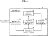
- FIG. 4 is a functional block diagram showing an example of a functional configuration of the information processing device 10 according to one embodiment of the present disclosure.
- the information processing device 10 includes a measured data acquisition unit 101, an amount-of-fluorescence analysis unit 102, a reference spectrum generation unit 103, a storage unit 110, and a display control unit 120.
- the measured data acquisition unit 101 acquires measured data generated by the measurement device 20 from the measurement device 20.
- measured data of the microparticles S acquired from the measurement device 20 is, for example, data representing the intensity of a spectrum generated by applying laser light to one or more microparticles S.
- a time slot exists although being minute.
- the accumulation intensity, maximum intensity, average intensity, or the like in the minute time slot is used for measured data according to the present embodiment.
- the measured data acquisition unit 101 stores the acquired measured data in the storage unit 110.
- the measured data acquisition unit 101 may store the acquired measured data in the storage unit 110 in association with time information such as the date and time when the measured data is acquired, information related to a measurement condition of the measurement device 20, or the like.
- the measured data acquisition unit 101 may output the measured data directly to the amount-of-fluorescence analysis unit 102 for real-time analysis.
- the amount-of-fluorescence analysis unit 102 separates the fluorescence spectrum related to measured data acquired from the measured data acquisition unit 101 or the storage unit 110 into spectra of respective fluorochromes that label the microparticles S (and autofluorescence spectra derived from the microparticles S), and analyzes the amount of fluorescence from the intensity per separated spectrum.
- a reference spectrum is used for separating the fluorescence spectrum.
- the reference spectrum is a spectrum obtained by measuring and standardizing a simply-stained sample simply stained with each fluorochrome. This reference spectrum is generated by the reference spectrum generation unit 103.
- the amount-of-fluorescence analysis unit 102 analyzes the amount of fluorescence of each fluorochrome by fitting the reference spectrum of each fluorochrome used for multiple staining of the microparticles S into fluorescence spectra related to measured data of the microparticles S. Fitting of the reference spectrum is performed by any publicly-known approach such as the least squares method.
- FIG. 5 is a diagram for describing the amount-of-fluorescence analysis processing performed by the amount-of-fluorescence analysis unit 102 according to the present embodiment.
- the amount-of-fluorescence analysis unit 102 first selects a fluorochrome that labels the microparticle S by a user operation or the like, and acquires the reference spectrum of the fluorochrome from the storage unit 110.
- a fluorochrome that labels the microparticle S by a user operation or the like
- the reference spectrum of the fluorochrome from the storage unit 110.
- FIG. 5 reference spectra of five types of fluorochromes: FITC; PE; ECD; PC5; and PC7 are shown.
- the amount-of-fluorescence analysis unit 102 acquires measured data of the microparticles S labeled with the above-described fluorochromes and the reference spectrum corresponding to each fluorochrome from the storage unit 110, and separates fluorescence spectra related to the measured data per fluorochrome.
- the fluorescence spectra shown in FIG. 5 are superimposed reference spectra of the fluorochromes used for labeling. That is, the amount-of-fluorescence analysis unit 102 analyzes the fluorescence intensity of each reference spectrum by fitting each reference spectrum into the fluorescence spectra. Fluorescence spectra resulting from the respective fluorochromes obtained by fitting are as shown in FIG. 5 .
- the reference spectrum and the fluorescence spectrum of each fluorochrome after fitting are identical in shape, whilst the intensity of the fluorescence spectrum is changed by weighting in fitting. The intensity corresponds to the amount of fluorescence of each fluorochrome.
- the amount-of-fluorescence analysis unit 102 analyzes the amount of fluorescence of each fluorochrome from the intensity of each fluorescence spectrum. Accordingly, the degree of the amount of fluorescence of the fluorochromes included in the microparticles S can be learned.
- the amount-of-fluorescence analysis unit 102 may separate the fluorescence spectra related to the measured data using the approach disclosed in Patent Literature 1 above ( JP 2013-24792A1 ), for example, and analyze the amount of fluorescence of each fluorochrome.
- the amount-of-fluorescence analysis unit 102 is also capable of analyzing the amount of fluorescence of autofluorescence spectra obtained from unstained microparticles.
- the amount-of-fluorescence analysis unit 102 stores data related to the analysis result in the storage unit 110. On this occasion, the amount-of-fluorescence analysis unit 102 may store the data related to the analysis result in the storage unit 110 in association with time information such as the date and time when the data is generated, information related to measured data, or the like. In addition, the amount-of-fluorescence analysis unit 102 may output the analysis result to the display control unit 120. A screen related to the analysis result is presented to a user by the display control unit 120.
- the amount-of-fluorescence analysis unit 102 may present the analysis result to the user as a printed material via an output device such as a printer, or may output data related to the analysis result to various recording media such as a CD, a DVD, a Blu-ray (registered trademark) disc, a USB memory, or an external HDD (Hard Disk Drive), and the like.
- the amount-of-fluorescence analysis unit 102 may output data related to the analysis result to an external device with which the information processing device 10 according to the present embodiment is capable of communicating via various communication networks.
- the reference spectrum generation unit 103 generates a reference spectrum on the basis of the fluorescence spectra related to measured data of unstained microparticles or microparticles labeled with at least one fluorochrome, acquired from the storage unit 110.
- the reference spectrum is a spectrum for reference for analyzing the amount of fluorescence of fluorochromes used for labeling the microparticles from one fluorescence spectrum by the amount-of-fluorescence analysis unit 102, as described above.
- the reference spectrum generation unit 103 performs the following processing when calculating the reference spectrum of one fluorochrome. Specifically, the reference spectrum generation unit 103 first acquires measured data of microparticles labeled only with one fluorochrome and measured data of unstained microparticles from the storage unit 110. By performing statistical processing for these pieces of measured data, the reference spectrum generation unit 103 calculates the reference spectrum of the one fluorochrome. In addition, by performing statistical processing only for the measured data of unstained microparticles, the reference spectrum generation unit 103 may calculate the reference spectrum related to autofluorescence spectra of the microparticles.
- the reference spectrum generation unit 103 stores data related to the reference spectrum in the storage unit 110.
- the reference spectrum generation unit 103 may store the data related to the reference spectrum in the storage unit 110 in association with time information such as the date and time when the data is generated, information related to measured data, or the like.
- the reference spectrum generation unit 103 may output the data related to the reference spectrum to the display control unit 120.
- the data related to the reference spectrum is presented to the user by the display control unit 120.
- the storage unit 110 is storage means that the information processing device 10 includes, and stores information obtained by each functional unit that the information processing device 10 has, and the like. In addition, the storage unit 110 outputs stored information as appropriate in accordance with a request from each functional unit that the information processing device 10 has. Measured data acquired by the measured data acquisition unit 101, data related to the analysis result analyzed by the amount-of-fluorescence analysis unit 102, data related to the reference spectrum calculated by the reference spectrum generation unit 103, and the like, for example, may be stored in the storage unit 110. In addition, execution data such as programs corresponding to various applications that the display control unit 120 utilizes for displaying various types of information on a display screen may be stored in the storage unit 110.
- various parameters, temporary data, or the like that may occur during processing performed by the information processing device 10 may be stored in the storage unit 110 as appropriate.
- the storage unit 110 may be provided with various databases.
- the various databases may include, for example, a database that stores the above-described measured data, data related to the analysis result, or data related to the reference spectrum.
- the storage unit 110 is provided so as to allow each functional unit that the information processing device 10 according to the present embodiment has to freely perform reading and writing.
- the display control unit 120 performs display control of a display screen in a display device not shown such as a display that the information processing device 10 includes or a display device such as a display provided external to the information processing device 10.
- the display control unit 120 may perform display control of the display screen on the basis of data related to the analysis result obtained by the amount-of-fluorescence analysis unit 102.
- the display control unit 120 may perform display control of the display screen on the basis of data related to the reference spectrum generated by the reference spectrum generation unit 103.
- the display control allows the user of the information processing device 10 to learn information about the analysis result or reference spectrum.
- the reference spectrum is a spectrum used for analyzing the amount of fluorescence of each fluorochrome in the amount-of-fluorescence analysis unit 102, as described above. In order to analyze the amount of fluorescence of each fluorochrome with high accuracy, the correctness of the shape of the reference spectrum is required.
- the reference spectrum generation unit 103 performs processing of generating the reference spectrum of one fluorochrome (or autofluorescence of microparticles) in the following procedure, for example. First, the reference spectrum generation unit 103 acquires measured data of microparticles labeled only with the one fluorochrome and measured data of unstained microparticles from the storage unit 110. Next, the reference spectrum generation unit 103 performs statistical processing (for example, averaging processing) for measured data related to autofluorescence, and obtains a spectrum related to autofluorescence having been averaged (an averaged autofluorescence spectrum).
- statistical processing for example, averaging processing
- the reference spectrum generation unit 103 subtracts the above-described averaged autofluorescence spectrum from each of a plurality of fluorescence spectra related to measured data of microparticles labeled only with the above-described one fluorochrome.
- the reference spectrum generation unit 103 normalizes a spectrum total sum for each of the plurality of fluorescence spectra. Then, the reference spectrum generation unit 103 averages the normalized spectrum. A spectrum obtained by the averaging will be referred to as an averaged fluorescence spectrum.
- the reference spectrum generation unit 103 normalizes the intensity of the averaged fluorescence spectrum. Accordingly, the reference spectrum of the above-described one fluorochrome is generated.
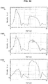
- FIG. 6 is a diagram showing an example of the reference spectrum generated by the reference spectrum generation unit 103.
- a graph G61 in FIG. 6 shows an example of a plurality of fluorescence spectra related to measured data used for calculation of the reference spectrum
- a graph G62 in FIG. 6 shows an example of the reference spectrum generated by the reference spectrum generation unit 103 on the basis of the plurality of fluorescence spectra shown in the graph G61.
- the horizontal axis of the graphs representing the spectra shown in the graph G61 and the graph G62 indicates the PMT channel (that is, equivalent to the wavelength), and the vertical axis indicates the intensity of the spectra.
- peaks observed at 5 ch to 20 ch and peaks observed in the vicinity of 30 ch to 55 ch mainly exist.
- the peaks observed at 5 ch to 20 ch are peaks resulting from a fluorochrome A that labels microparticles
- the peaks observed in the vicinity of 30 to 55 ch are peaks resulting from auto fluorescence of microparticles.
- the reference spectrum generation unit 103 By subtracting the averaged autofluorescence spectrum calculated separately from each of the fluorescence spectra shown in the graph G61 and averaging and normalizing fluorescence spectra after subtraction, the reference spectrum generation unit 103 generates the reference spectrum shown in the graph G62. If variations in measured data used when generating the reference spectrum are variations of the degree as shown in the graph G61, it is possible to obtain a reference spectrum showing a peak resulting from the fluorochrome A, as shown in the graph G62.
- the accuracy of the generated reference spectrum is reduced. For example, (1) in the case where an abnormal value is included in a spectrum related to measured data, or (2) in the case where fluorescence is weak, and a noise included in a spectrum becomes relatively large, it is considered that the accuracy of the generated reference spectrum may be reduced.
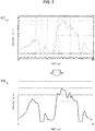
- FIG. 7 is a diagram showing an example of a reference spectrum generated by the reference spectrum generation unit 103 in the case where an abnormal value is included in measured data.
- a graph G71 in FIG. 7 shows an example of a plurality of fluorescence spectra related to measured data used for generation of the reference spectrum
- a graph G72 in FIG. 7 shows an example of a reference spectrum generated on the basis of the plurality of fluorescence spectra shown in the graph G71.
- a fluorochrome that labels microparticles used for generation of the reference spectrum shown in FIG. 7 is the fluorochrome A similarly to the case of FIG. 6 .
- a spectrum (referred to as an abnormal spectrum) mainly shown in the graph G71 is an imaginary spectrum obtained by multiplying a spectrum related to one piece of measured data by 100. That is, the abnormal spectrum indicates approximately 100 times the intensity of spectra related to other pieces of measured data.
- the peak resulting from autofluorescence particularly at 30 ch to 55 ch will be left even after subtraction of the averaged autofluorescence spectrum. Then, the peak resulting from autofluorescence may be left as it is in the reference spectrum, as shown in the graph G72. If the reference spectrum generated in this manner is used for analyzing the amount of fluorescence as the reference spectrum of the fluorochrome A, an incorrect analysis result may be obtained.
- FIG. 8 is a diagram showing an example of a flow of reference spectrum generation processing.
- the averaged autofluorescence spectrum is subtracted from the plurality of fluorescence spectra i.
- the intensities of some wavelength bands of the fluorescence spectrum n may become lower than the intensities of the wavelength bands of the averaged autofluorescence spectrum. This is because the signal intensities obtained in the wavelength bands of the fluorescence spectrum n are low, and are strongly affected by a negatively acting noise.
- the intensities of some wavelength bands of the spectrum after subtraction indicate negative values.
- a schematic spectrum F83 in FIG. 8 in the processing of normalizing the total sum of the spectra after subtraction, the negative values are excessively weighted in the normalization. Accordingly, in the processing of averaging the spectra after normalization, a negatively affected averaged fluorescence spectrum is obtained as shown in a schematic spectrum F84 in FIG. 8 , and thus, it is possible that the shape of the reference spectrum normalized by the spectrum intensity is significantly deviated from the shape of an actual fluorescence spectrum obtained from one fluorochrome, as shown in a schematic spectrum F85 in FIG. 8 . In addition, it is possible in some cases that a negative intensity is included in the reference spectrum.
- the amount of fluorescence of other fluorochromes that may indicate intensities in the wavelength band may be analyzed erroneously.
- the event indicated in (1) in which an abnormal value is included in measured data may be caused by the state of a flow of microparticles in the microchannel, the size or mass of the microparticles, adhesion between the microparticles, or the like when generating measured data in the measurement device 20, for example. For example, light detected at a previous time may be detected again because of turbulence of the microparticles (carry-over). Accordingly, an abnormal value is included in the measured data.
- the event indicated in (2) in which fluorescence becomes weak may occur, for example, in the case where the amount of fluorescence that labels the microparticles is small, in the case where the intensity of light emitted from the fluorochrome or microparticles is low, or the like.
- the event indicted in (1) is an event that may occur accidentally in the measurement device 20.
- the event indicted in (2) is an event that may occur unavoidably depending on properties that microparticles as targets of measurement may inherently have or the amount of fluorescence of the fluorochrome used for analysis that may be included in the microparticles. Therefore, even if measured data including an abnormal spectrum or measured data including a weak spectrum is acquired when generating the reference spectrum, it is required to avoid using these pieces of measured data.
- an information processing device when generating the reference spectrum, first extracts a spectrum indicating an outlier among a plurality of spectra (a group of spectra) obtained from microparticles that exhibit one fluorescent property through statistical processing, and excludes the extracted spectrum indicating an outlier from the above-described group of spectra. Then, the information processing device calculates the reference spectrum using the group of spectra from which the spectrum indicating an outlier has been excluded.
- the information processing device when generating the reference spectrum of one fluorochrome, performs the above-described statistical processing for each of a plurality of spectra (a first spectra group) obtained from microparticles labeled with one fluorochrome and a plurality of spectra (a second spectra group) obtained from microparticles not labeled with the one fluorochrome. Then, the information processing device excludes a spectrum indicating an outlier from each of the first spectra group and the second spectra group. Further, the information processing device averages each of the first spectra group and the second spectra group after exclusion of outliers, and subtracts the average spectrum of the second spectra group from the average spectrum of the first spectra group to calculate the reference spectrum.
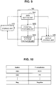
- FIG. 9 is a functional block diagram showing an example of a functional configuration of the reference spectrum generation unit 103 according to the first embodiment of the present disclosure.
- the reference spectrum generation unit 103 includes a data setting unit 1031, a statistical processing unit 1032, and a reference spectrum calculation unit 1033.
- the data setting unit 1031 acquires measured data to be used for generation of the reference spectrum from the storage unit 110, and performs setting and the like of data to be used for subsequent processing. For example, the data setting unit 1031 may perform (a) selection of a light-emitting element, (b) acquisition of measured data, and (c) correction of measured data.
- the data setting unit 1031 selects a light-emitting element related to the reference spectrum which is a target of generation.
- the light-emitting element in the present specification includes one substance, microparticle, and the like that exhibits one response property with respect to light.
- the substance means a fluorochrome, for example.
- the data setting unit 1031 selects a light-emitting element related to the reference spectrum which is a target of generation through user's selection.
- FIG. 10 is a diagram for describing fluorochrome selection processing performed by the data setting unit 1031 according to the present embodiment.
- identification symbols CD1, CD2, ..., Neg
- types FITC, PE, ..., Negative
- fluorochromes shown in the table of FIG. 10 may be fluorochromes corresponding to measured data stored in the storage unit 110, or may be all or part of fluorochromes whose spectra can be measured by the measurement device 20.
- the display control unit 120 may cause a display device or the like to display the table shown in FIG. 10 .
- the data setting unit 1031 may select a light-emitting element related to the reference spectrum which is a target of generation through an operation performed by a user having viewed the table.
- the data setting unit 1031 may select a light-emitting element related to the reference spectrum which is a target of generation among the light-emitting elements shown in the table through a user operation.
- the data setting unit 1031 may perform processing of adding the fluorochrome to the table through an input operation or the like by the user.
- the data setting unit 1031 acquires measured data corresponding to the selected light-emitting element from the storage unit 110.
- the acquired measured data may be, for example, measured data acquired by the measurement device 20 for fluorescence emitted from microparticles labeled with the selected fluorochrome, or measured data acquired by the measurement device 20 for autofluorescence of microparticles.
- the measured data includes spectra obtained from the microparticles.
- the spectra include, for example, fluorescence spectra or autofluorescence spectra related to fluorescence or autofluorescence emitted from the microparticles. Measurement of fluorescence or autofluorescence may be previously performed prior to the reference spectrum generation processing, or may be performed in parallel to the reference spectrum generation processing.
- the measurement device 20 acquires measured data of microparticles labeled only with the one fluorochrome.
- microparticles to be used for generation of the reference spectrum are unified by the same type of particles that may exhibit the same autofluorescence spectrum.
- the data setting unit 1031 acquires measured data corresponding to the selected light-emitting element from the storage unit 110 through user's selection.
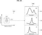
- FIG. 11 to FIG. 13 are diagrams for describing measured data acquisition processing in the case where FITC, PE, and Negative (unstained) are selected, and are diagrams showing examples of the distribution of fluorescence spectra related to the acquired measured data.
- a graph G111 and a graph G112 in FIG. 11 are a diagram showing the distribution of fluorescence intensities in specific wavelengths of the fluorescence spectrum of FITC and a diagram showing integrated data of the fluorescence spectrum of FITC.
- FIG. 12 are a diagram showing the distribution of fluorescence intensities in specific wavelengths of the fluorescence spectrum of PE and a diagram showing integrated data of the fluorescence spectrum of PE.
- a graph G131 and a graph G132 in FIG. 13 are a diagram showing the distribution of fluorescence intensities in specific wavelengths of the fluorescence spectrum of Negative and a diagram showing integrated data of the fluorescence spectrum of Negative. Note that the horizontal axis and the vertical axis in the graph G111, the graph G121, and the graph G131 in FIG. 11 to FIG. 13 indicate fluorescence intensities detected in an X channel and a Y channel of PMT (that is, fluorescence intensities in first and second wavelength bands corresponding to the X channel and the Y channel).
- the horizontal axis in the graph G112, the graph G122, and the graph G132 in FIG. 11 to FIG. 13 indicates the wavelength.
- the fluorescence spectrum obtained for each microparticle is a spectrum including fluorescence intensities detected in a plurality of PMTs.
- contour colors shown in the graph G112, the graph G122, and the graph G132 correspond to integrated data of a plurality of fluorescence spectra related to measured data.
- the data setting unit 1031 first acquires measured data about microparticles labeled with FITC from the storage unit 110. Then, the data setting unit 1031 may cause an intensity distribution chart as shown in the graph G111 to be displayed on a display device or the like by the display control unit 120. For example, as shown in the graph G111, fluorescence intensities in the first wavelength band and the second wavelength band of the fluorescence spectrum related to the acquired measured data may be plotted. A plot 1001 corresponds to measured data related to a group of microparticles labeled with FITC.
- the data setting unit 1031 selects the plot 1001 by a user operation or the like.
- the data setting unit 1031 may set a frame 1011 so as to enclose the plot 1001 through an input operation or the like by the user. Accordingly, measured data corresponding to the plot enclosed by the frame 1011 is acquired.
- the shape and size of the frame 1011, and the method of setting the frame 1011 are not particularly limited.
- the graph G112 indicates integrated data of fluorescence spectra related to the measured data shown in the graph G111.
- the integrated data may be displayed on the display device or the like by the display control unit 120. Accordingly, the user can check the validity of the acquired measured data.
- measured data corresponding to a plot 1002 enclosed by a frame 1012 and a plot 1003 enclosed by a frame 1013 are acquired by the data setting unit 1031, similarly to the example shown in FIG. 11 .
- the data setting unit 1031 may acquire all pieces of measured data related to the fluorochrome selected in the light-emitting element selection processing from the storage unit 110. That is, the data setting unit 1031 may acquire all pieces of measured data related to the fluorochrome at the time point when a light-emitting element is selected, without performing measured data selection and acquisition processing as shown in FIG. 11 to FIG. 13 .
- the data setting unit 1031 may perform processing of correcting the acquired measured data. Correction as stated herein is, for example, correction for non-uniformity of photoelectric conversion properties in PMTs or variations in flowing position of microparticles within the microchannel. These corrections may be performed on the basis of a technology described in JP2013-61244A or WO2013/183345 , for example.
- correction processing may be performed previously by the measurement device 20, or may be performed by the measured data acquisition unit 101 or the like shown in FIG. 4 .
- the data setting unit 1031 may not perform correction processing again.
- the correction processing may not necessarily be performed.
- the function related to the correction processing may not necessarily be included in the reference spectrum generation unit 103.
- the function related to the correction processing may be executed by the measured data acquisition unit 101, or may be executed as a function that the information processing device 10 has.
- the correction processing may also be performed in the above-described amount-of-fluorescence analysis unit 102.
- the data setting unit 1031 sets measured data concerning a light-emitting element related to the reference spectrum which is a target of generation by performing the above processing.
- the set measured data is output to the statistical processing unit 1032.
- the set measured data may be stored in the storage unit 110.
- the statistical processing unit 1032 performs statistical processing for a group of spectra obtained by applying light to a group of microparticles that exhibit one response property with respect to light, and on the basis of the result of the statistical processing, excludes a spectrum indicating an outlier from the group of spectra.
- the statistical processing unit 1032 performs statistical processing for a plurality of spectra (a group of spectra) related to measured data, and on the basis of the result of the statistical processing, excludes a spectrum indicating an outlier from the group of spectra.
- one response property with respect to light indicates a fluorescent property, for example.
- the fluorescent property means a property related to fluorescence derived from a fluorochrome that labels microparticles, or a property related to autofluorescence derived from unstained microparticles.
- a group of microparticles that exhibit one response property with respect to light means that each of the group of microparticles exhibits a similar response property.
- one response property with respect to light exhibited by the group of microparticles may be a similar fluorescent property obtained from simply-stained or multi-stained microparticles, or may be a fluorescent property related to autofluorescence obtained from unstained microparticles.
- the group of spectra corresponding to these response properties may have spectra of a similar shape as a whole although some shifts exist among microparticles.
- the outlier is an outlier for the intensities of a plurality of spectra.
- the one spectrum may be a spectrum indicating an outlier.
- the one spectrum may be a spectrum indicating an outlier. The degree (threshold value) of deviation in the intensity or shape of the above-described spectrum is determined in accordance with the above-described statistical processing.
- the statistical processing unit 1032 performs reference spectrum setting processing through use of RANdom SAmple Consensus (RANSAC) as an example of statistical processing for excluding a spectrum indicating an outlier.
- RANSAC RANdom SAmple Consensus
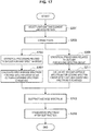
- FIG. 14 is a flow chart related to an example of reference spectrum setting processing through use of RANSAC performed by the statistical processing unit 1032 according to the present embodiment.
- FIG. 15 is a diagram for describing an example of reference spectrum setting processing performed by the statistical processing unit 1032 according to the present embodiment.
- N pieces of measured data related to one fluorochrome (assumed as the fluorochrome A) have been set by the data setting unit 1031.
- the number N of pieces of measured data to be used for the setting processing is not particularly limited, but is preferably more than or equal to a predetermined number in order to exclude a spectrum indicating an outlier.
- the predetermined number may be, for example, twice the number n of pieces of data to be extracted in step S101 below.
- the statistical processing unit 1032 calculates parameters related to Gr.m from measured data included in the data set of Gr.m (S103).
- the statistical processing unit 1032 calculates an average value ave I (m, l) and a standard deviation ⁇ I (m, l) of the intensity of the PMT channel l for each PMT channel.
- the average value ave I (m, l) and the standard deviation ⁇ I (m, l) become parameters related to Gr.m.
- the statistical processing unit 1032 compares measured data other than the data set of Gr.m and parameters related to Gr.m (S105). Specifically, the statistical processing unit 1032 may calculate an error err (m, p, k, l) between the intensity I (p, k, l) of the PMT channel 1 included in each piece of measured data D (p, k) (p ⁇ m) and the average value ave I (m, l), respectively.
- the statistical processing unit 1032 may calculate a correlation coefficient R 2 (m, p, k) between a spectrum S D (p,k) expressed by the intensity I (p, k, l) of the measured data D (p, k) and a spectrum S ave (m) expressed by the average value ave I (m, l), respectively.
- the spectrum S D (p, k) is a spectrum including the intensity I in all the PMT channels
- the spectrum S ave (m) is a spectrum including the average value ave I (m, l) related to all the PMT channels.
- the statistical processing unit 1032 verifies whether or not the error and correlation coefficient obtained in step S105 are included in predetermined ranges for each piece of measured data except the data set of Gr.m, and calculates the number of pieces of measured data (outlier-containing measured data) in which the error and the correlation coefficient are not included in the predetermined ranges (S107). Specifically, in the case of calculating the number of pieces of outlier-containing measured data on the basis of the error, the statistical processing unit 1032 may first verify whether or not the error err (m, p, k, l) falls below a first predetermined threshold value th1 per PMT channel of each piece of measured data.
- the statistical processing unit 1032 may count the measured data as outlier-containing measured data.
- the first predetermined threshold value th1 may be set on the basis of the standard deviation ⁇ I (m, l) related to the data set of Gr.m.
- the statistical processing unit 1032 may verify whether or not the correlation coefficient R 2 (m, p, k) falls below a second predetermined threshold value th2 for each piece of measured data.
- the second predetermined threshold value th2 may be set as appropriate on the basis of the number of pieces of calculated outlier-containing measured data, the accuracy of a reference spectrum to be obtained subsequently, or the like.
- the statistical processing unit 1032 performs processing related to step S105 and step S107 for all pieces of measured data except the data set of Gr.m (S109).
- the statistical processing unit 1032 calculates at least either of the number N err (m) of pieces of outlier-containing measured data related to the error about the data set of Gr.m and the number N cor (m) of pieces of outlier-containing measured data related to the correlation coefficient, from the above-described processing result.
- the statistical processing unit 1032 repeatedly performs processing related to the above-described steps S101 to S107 for all the data sets (Gr.1 to Gr.M). Accordingly, as shown in a schematic view F152 and a table F153 in FIG. 15 , parameters (the average value ave I (m, l) and the standard deviation ⁇ I (m, l)) are calculated for all the data sets, and in addition, at least either of the number N err (m) of pieces of outlier-containing measured data related to the error and the number N cor (m) of pieces of outlier-containing measured data related to the correlation coefficient is calculated for all the data sets.
- parameters the average value ave I (m, l) and the standard deviation ⁇ I (m, l)
- the statistical processing unit 1032 specifies a data set Gr.m 1 in which the number of pieces of outlier-containing measured data is the smallest (Sill). Specifically, as shown in the table F153, the statistical processing unit 1032 specifies, as Gr.m 1 , a data set in which at least either of the number N err (m) of pieces of outlier-containing measured data related to the error (Error) and the number N cor (m) of pieces of outlier-containing measured data related to the correlation coefficient (CC) is the smallest.
- a data set in which the number N err (m) of pieces of outlier-containing measured data related to the error is the smallest is Gr.1.
- a data set in which the number N cor (m) of pieces of outlier-containing measured data related to the correlation coefficient is the smallest is Gr.M-1.
- Measured data included in the data set of Gr.m 1 specified here is a measured data group having the fewest variations.
- the data set becomes the most appropriate data set for setting the reference spectrum to be used as a reference for specifying a spectrum indicating an outlier. Note that, for specification of Gr.m 1 , whether to use either the number N err (m) of pieces of outlier-containing measured data related to the error or the number N cor (m) of pieces of outlier-containing measured data related to the correlation coefficient will be described later.
- the statistical processing unit 1032 sets the reference spectrum on the basis of the data set of Gr.m 1 .
- the statistical processing unit 1032 may set a spectrum indicated by the average value ave I (m 1 , l) which is a parameter related to the data set of Gr.m 1 as the reference spectrum.
- the statistical processing unit 1032 calculates an error and a correlation coefficient between spectra related to all pieces of measured data and the reference spectrum, respectively (S113 in FIG. 14 ). Specifically, in the case of calculating the error, the statistical processing unit 1032 may calculate an error err (m 1 , m, k, l) between the intensity I (m, k, l) included in the measured data (m, k) and the average value ave I (m 1 , l) per PMT channel of all pieces of measured data, respectively.
- the statistical processing unit 1032 may calculate the correlation coefficient R 2 (m 1 , m, k) between a spectrum S D (m, k) expressed by the intensity I (m, k, l) and the spectrum S ave (m 1 ) expressed by the average value ave I (m 1 , l) for all pieces of measured data, respectively.
- These types of calculation processing may be similar to the processing related to step S105.
- the statistical processing unit 1032 verifies whether or not the error and correlation coefficient obtained in step S113 are included in predetermined ranges for each of all pieces of measured data, and sets measured data in which the error and the correlation coefficient are not included in the predetermined ranges as measured data (outlier-containing measured data) including a spectrum indicating an outlier (S115).
- the statistical processing unit 1032 may first verify whether or not the error err (m 1 , m, k, l) falls below a third predetermined threshold value th3 per PMT channel of each piece of measured data. At this time, for example, if even one of the 1 errors err (m 1 , m, k, l) included in the measured data (m, k) falls below outside the above-described third predetermined threshold value th3, the statistical processing unit 1032 may specify that the measured data is outlier-containing measured data.
- the third predetermined threshold value th3 may be set on the basis of the standard deviation ⁇ I (m 1 , l) related to the data set of Gr.m 1 .
- the third predetermined threshold value th3 may be identical to the above-described first predetermined threshold value th1.
- the statistical processing unit 1032 may verify whether or not the correlation coefficient R 2 (m 1 , m, k) falls below a fourth predetermined threshold value th4 for each piece of measured data.
- the fourth predetermined threshold value th4 may be set as appropriate on the basis of the number of pieces of calculated outlier-containing measured data, the accuracy of the reference spectrum to be obtained subsequently, or the like.
- the fourth predetermined threshold value th4 may be identical to the above-described second predetermined threshold value th2.
- the statistical processing unit 1032 can specify measured data including an outlier in accordance with a flow chart shown in FIG. 14 .
- the statistical processing unit 1032 excludes the specified measured data from a group of measured data corresponding to a group of spectra. That is, the statistical processing unit 1032 excludes a spectrum indicating an outlier from a group of spectra.
- the group of measured data after measured data including an outlier is excluded is output to the reference spectrum calculation unit 1033 which will be described later. Note that the situation of processing performed by the statistical processing unit 1032 and the result of processing may be stored in the storage unit 110 as appropriate, or may be displayed on a display device or the like as appropriate by the display control unit 120.
- the statistical processing unit 1032 specifies outlier-containing measured data on the basis of an excluding condition of at least either the error or correlation coefficient.
- the tendencies of shapes of spectra related to outlier-containing measured data specified for respective excluding conditions are different from each other.
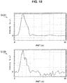
- FIG. 16 is a diagram showing average spectra of spectra related to measured data including or not including an outlier.
- a graph G161 in FIG. 16 is an average spectrum (effective average spectrum) of spectra related to measured data not including an outlier.
- a graph G162 in FIG. 16 is an average spectrum (error-induced outlier-containing average spectrum) of spectra related to outlier-containing measured data specified on the basis of the error.
- a graph G163 in FIG. 16 is an average spectrum (correlation coefficient-induced outlier-containing average spectrum) of spectra related to outlier-containing measured data specified on the basis of the correlation coefficient.
- a spectrum including an abnormal value or a strong noise is excluded under an excluding condition related to the error, while a spectrum whose shape of the spectrum is different from the shapes of a large number of other spectra is excluded under an excluding condition related to the correlation coefficient.
- Such excluding conditions may be changed in accordance with the type of spectra obtained from microparticles, used in calculation of the reference spectrum.
- the reference spectrum calculation unit 1033 in the case of generating the reference spectrum of the fluorochrome A, for example, fluorescence spectra (the first spectra group) obtained from microparticles labeled only with the fluorochrome A and fluorescence spectra (the second spectra group) of unstained microparticles are used.
- the statistical processing unit 1032 excludes a spectrum indicating an outlier from each of the first spectra group and the second spectra group prior to calculation of the reference spectrum of the fluorochrome A.
- the statistical processing unit 1032 may use the excluding condition related to the correlation coefficient as an excluding condition for excluding a spectrum indicating an outlier from the first spectra group.
- the excluding condition related to the correlation coefficient As described above, for analyzing the amount of fluorescence by deconvolution of fluorescence spectra derived from a plurality of fluorochromes, high accuracy of the shape of the generated reference spectrum is required. Thus, by excluding a spectrum indicating an outlier on the basis of the correlation coefficient related to the spectrum shape, only spectra having similar shapes can be obtained as the first spectra group. Therefore, the accuracy of the reference spectrum to be calculated in subsequent processing can be increased.
- the statistical processing unit 1032 may use the excluding condition related to the error as an excluding condition for excluding a spectrum indicating an outlier from the second spectra group. Since spectra included in the second spectra group are autofluorescence spectra, it is highly likely that the spectra are not necessarily uniform in shape in accordance with the shape, size, property, or the like of microparticles. Thus, in the case of using the excluding condition related to the correlation coefficient, the number of spectra specified as spectra indicating outliers will be increased. Then, the accuracy of the reference spectrum to be calculated in subsequent processing can be reduced since the denominator of spectra is reduced. Therefore, in the case of excluding a spectrum indicating an outlier from the second spectra group, the spectrum indicating an outlier may be excluded only using the excluding condition related to the error.
- excluding conditions different between the first spectra group and the second spectra group may be used. That is, appropriate excluding conditions may be used in accordance with the shape uniformity of spectra included in each of the spectra group, or the like. Accordingly, the accuracy of the generated reference spectrum can be improved.
- the statistical processing unit 1032 may further use the excluding condition related to the error as an excluding condition for excluding a spectrum indicating an outlier from the first spectra group. Accordingly, a spectrum having high correlation of spectrum shape but including an abnormal value or the like can be excluded from the first spectra group.
- the statistical processing unit 1032 may evaluate the uniformity of a group of spectra (measured data) used for generation of the reference spectrum, using the result of statistical processing for specifying and excluding a spectrum indicating an outlier from the group of spectra.
- the result of statistical processing may be, for example, the number of pieces of measured data in which the error or correlation coefficient falls outside the predetermined range, calculated in step S107 of FIG. 14 . If this number of pieces of outlier-containing measured data is large as a whole, it is understood that measured data used for generation of the reference spectrum is not high. In addition, if the number of pieces of outlier-containing measured data calculated using an average value or the like related to some data sets is large, it is understood that the uniformity of measured data included in the some data sets is not high.
- the result of statistical processing may be the correlation coefficient calculated in step S113 of FIG. 14 , for example. It is understood that, if the correlation coefficient is high, the uniformity of measured data is high, and if the correlation coefficient is low, the uniformity of measured data is not high.
- Information related to such an evaluation of the uniformity of measured data may be displayed on the display device by the display control unit 120. Accordingly, the user can learn the uniformity of measured data used for generation of the reference spectrum.
- the statistical processing unit 1032 performs processing of excluding measured data including an outlier (a spectrum indicating an outlier) through statistical processing by means of robust estimation such as RANSAC, whilst the present technology is not limited to such an example.
- the statistical processing may be statistical processing by means of a publicly-known algorithm concerning outlier removal. More specifically, the statistical processing may be statistical processing by means of an algorithm related to outlier removal through the least median of squares method (LMedS), M estimation method, least squares method (LMS), or Bayesian Filter.
- LMedS least median of squares method
- M estimation method least squares method
- LMS least squares method
- Bayesian Filter Bayesian Filter
- the outlier excluding condition may be provided similarly to RANSAC.
- the statistical processing unit 1032 may use an excluding condition based on the shapes of obtained spectra. Accordingly, a spectrum having a shape of low similarity can be excluded.
- the statistical processing unit 1032 may use an excluding condition based on the intensities of obtained spectra. Accordingly, a spectrum including an abnormal value or a strong noise can be excluded.
- the statistical processing unit 1032 may further use the excluding condition based on the intensities of obtained spectra. Accordingly, a spectrum having high correlation of spectrum shape but including an abnormal value or the like can be excluded.
- the functions of the statistical processing unit 1032 have been described above. Data related to the group of spectra after a spectrum indicating an outlier is excluded by the statistical processing unit 1032 is output to the reference spectrum calculation unit 1033.
- the statistical processing unit 1032 may store the data in the storage unit 110. On this occasion, the statistical processing unit 1032 may store the data in the storage unit 110 in association with time information such as the date and time when the data is generated, information related to measured data corresponding to the group of spectra, or the like.
- the statistical processing unit 1032 may output the data to the display control unit 120. A screen related to the data is presented to the user by the display control unit 120.
- the reference spectrum calculation unit 1033 calculates the reference spectrum using the group of spectra from which a spectrum indicating an outlier has been excluded. For example, in the case of calculating the reference spectrum of the fluorochrome A, first, in the statistical processing unit 1032, spectra indicating outliers are excluded from fluorescence spectra (the first spectra group) obtained from microparticles labeled only with the fluorochrome A and autofluorescence spectra (the second spectra group) obtained from unstained microparticles.
- the reference spectrum calculation unit 1033 calculates the reference spectrum of the fluorochrome A using the first spectra group (the first spectra group after statistical processing) and the second spectra group (the second spectra group after statistical processing) from which spectra indicating outliers have been excluded.
- the reference spectrum calculation unit 1033 does not perform processing of subtracting a second average spectrum (equivalent to the averaged autofluorescence spectrum) from spectra included in the first spectra group and processing related to normalization of the total sum of the spectra after subtraction as shown in the schematic spectrum F82 and the schematic spectrum F83 in FIG. 8 .
- a second average spectrum equivalent to the averaged autofluorescence spectrum
- the spectrum intensity after subtraction will be negative depending on noises included in the spectra.
- the total sum of spectra including negative intensities is normalized, the negative intensities will be further amplified. Accordingly, the accuracy of the reference spectrum obtained by averaging the respective spectra after normalization will be reduced.
- the present inventors have studied about a method for improving the problem related to reduction in accuracy as described above. As a result, the present inventors have arrived at reference spectrum calculation processing which will be indicated below.
- the reference spectrum calculation unit 1033 first calculates the first average spectrum obtained by averaging spectra included in the first spectra group after statistical processing and the second average spectrum obtained by averaging spectra included in the second spectra group after statistical processing. Then, the reference spectrum calculation unit 1033 calculates the reference spectrum by subtracting the second average spectrum from the first average spectrum.
- averaging stated herein means a simple average of all or part of spectra included in the first spectra group or the second spectra group.
- the reference spectrum calculation unit 1033 may standardize a spectrum obtained by subtraction to acquire the reference spectrum. Standardization stated herein means normalizing the peak intensity exhibited by the spectrum obtained by subtraction.
- the reference spectrum calculation unit 1033 calculates the reference spectrum by subtracting the second average spectrum from the first average spectrum after calculating the first average spectrum and the second average spectrum, whilst the present technology is not limited to such an example.
- the reference spectrum calculation unit 1033 may calculate the reference spectrum by subtracting the second average spectrum from each of the spectra included in the first spectra group and averaging the subtracted respective spectra.
- the reference spectrum calculation unit 1033 may calculate the second average spectrum obtained by averaging autofluorescence spectra obtained from unstained microparticles included in the second spectra group as the reference spectrum (autofluorescence reference spectrum) related to autofluorescence of microparticles.
- a spectrum indicating an outlier has already been excluded from the second spectra group by the statistical processing unit 1032. Therefore, the accuracy of the obtained autofluorescence reference spectrum becomes higher than the accuracy of spectra obtained from the second spectra group from which a spectrum indicating an outlier has not been excluded.
- the reference spectrum calculation unit 1033 may store data related to the calculated reference spectrum in the storage unit 110. On this occasion, the reference spectrum calculation unit 1033 may store the data in the storage unit 110 in association with time information such as the date and time when the data is generated, information related to measured data used for generation of the reference spectrum, or the like. In addition, the reference spectrum calculation unit 1033 may output the data to the display control unit 120. A screen related to the data is presented to the user by the display control unit 120.
- the reference spectrum of the fluorochrome A stored in the storage unit 110 is used for analyzing the amount of fluorescence of the fluorochrome A from fluorescence spectra obtained from microparticles labeled with at least one fluorochrome including the fluorochrome A in the amount-of-fluorescence analysis unit 102.
- the amount-of-fluorescence analysis unit 102 acquires data related to the reference spectrum of the fluorochrome A stored in the storage unit 110, and uses the reference spectrum for deconvolution of the fluorescence spectra. Accordingly, the amount of fluorescence of the fluorochrome A is analyzed.
- FIG. 17 is a flowchart showing an example of the processing performed by the reference spectrum generation unit 103 according to the first embodiment of the present disclosure.
- FIG. 17 is a flowchart showing an example of the processing performed by the reference spectrum generation unit 103 according to the first embodiment of the present disclosure.
- an example of processing of generating the reference spectrum of the fluorochrome A will be described.
- the data setting unit 1031 selects a light-emitting element to be a target of generation of the reference spectrum (here, selects the fluorochrome A) (S201).
- the data setting unit 1031 acquires measured data related to the fluorescence spectrum obtained from microparticles labeled with the fluorochrome A and an autofluorescence spectrum obtained from unstained microparticles from the storage unit 110.
- correction as stated herein may be, for example, correction based on the flowing position of microparticles within the microchannel or correction corresponding to non-uniformity of photoelectric conversion properties in the PMTs.
- processing (S205, S207) related to a spectra group (the first spectra group) including spectra related to the fluorochrome A and processing (S209, S211) related to a spectra group (the second spectra group) including autofluorescence spectra, corresponding to the measured data, are performed in parallel.
- the statistical processing unit 1032 first performs statistical processing related to an outlier for the first spectra group, and excludes a spectrum indicating an outlier from the first spectra group (S205).
- the reference spectrum calculation unit 1033 calculates a simple average spectrum (the first average spectrum) from the first spectra group after the spectrum indicating an outlier is excluded (S207).
- the statistical processing unit 1032 performs statistical processing related to an outlier for the second spectra group, and excludes a spectrum indicating an outlier from the second spectra group (S209). Then, the reference spectrum calculation unit 1033 calculates a simple average spectrum (the second average spectrum) from the second spectra group after the spectrum indicating an outlier is excluded (S211).
- the reference spectrum calculation unit 1033 subtracts the second average spectrum from the first average spectrum, and calculates the reference spectrum before standardization (S213). Then, the reference spectrum calculation unit 1033 standardizes the obtained reference spectrum before the standard (S215). Accordingly, the reference spectrum of the fluorochrome A is generated.
- the reference spectrum generation unit 103 An example of processing performed by the reference spectrum generation unit 103 according to the present embodiment has been described above. Note that, in an example of the processing performed by the above-described reference spectrum generation unit 103, the reference spectrum of the fluorochrome A is generated using measured data related to each of microparticles labeled with the fluorochrome A and unstained microparticles, whilst the present technology is not limited to such an example.
- the reference spectrum generation unit 103 may generate the reference spectrum of the fluorochrome A using measured data related to each of microparticles labeled with a plurality of fluorochromes (for example, the fluorochromes A, B, and C) and microparticles labeled with fluorochromes (for example, the fluorochromes B and C) other than the fluorochrome A.
- a plurality of fluorochromes for example, the fluorochromes A, B, and C
- microparticles labeled with fluorochromes for example, the fluorochromes B and C
- the statistical processing unit 1032 may exclude a spectrum indicating an outlier from each of the first spectra group including fluorescence spectra obtained from microparticles labeled with the fluorochromes A, B, and C and the second spectra group including fluorescence spectra obtained from microparticles labeled with the fluorochromes B and C.
- the reference spectrum calculation unit 1033 may subtract the average spectrum (the second average spectrum) of the second spectra group after excluding an outlier-containing spectrum from the average spectrum (the first average spectrum) of the first spectra group after excluding an outlier-containing spectrum, and may standardize the spectrum after subtraction. Accordingly, it is possible to obtain the reference spectrum of the fluorochrome A.
- FIG. 18 shows examples of a reference spectrum generated by processing performed by the reference spectrum generation unit 103 according to the first embodiment of the present disclosure and a reference spectrum generated by the reference spectrum generation processing shown in FIG. 8 .
- a graph G181 in FIG. 18 is an example of the reference spectrum generated by the processing performed by the reference spectrum generation unit 103 according to the present embodiment.
- a graph G182 in FIG. 18 is an example of the reference spectrum generated by the reference spectrum generation processing shown in FIG. 8 .
- the reference spectra shown in FIG. 18 were generated using measured data obtained by performing measurements by the measurement device 20 on lymphocytes labeled with a fluorochrome called AlexaFlour532.
- the reference spectrum generated by the reference spectrum generation unit 103 has less noises. This is because a spectrum indicating an outlier has been excluded from a group of spectra in the statistical processing unit 1032.
- standardization by means of the total sum of spectra is not performed in the reference spectrum calculation unit 1033, but standardization is performed after averaging the spectra, wavelength bands having negative intensities hardly exist.
- a spectrum indicating an outlier can be excluded from a group of spectra. Accordingly, it is possible to prevent measured data indicating an abnormal value, a noise, or the like from being used for the reference spectrum generation processing by means of a measurement condition or the like. Therefore, even if measured data including an abnormal value that occurs irregularly is used in measurements, the accuracy of the reference spectrum generated can be maintained.
- the reference spectrum generation unit 103 after averaging the group of spectra from which a spectrum indicating an outlier has been excluded, averaged spectra are standardized. Accordingly, many noises that may be included in spectra obtained by weak signals are smoothed. Since spectra standardization processing is performed after this averaging processing, the reference spectrum is less likely to include negative intensities. Therefore, even if signals related to fluorescence or autofluorescence obtained from microparticles are weak, the reference spectrum can be generated with high accuracy.
- processing of generating the reference spectrum of one fluorochrome has been specifically described using measured data related to fluorescence spectra obtained from microparticles labeled with one fluorochrome and autofluorescence spectra obtained from unstained microparticles, whilst the reference spectrum generation processing according to the present embodiment is not limited to such an example. That is, the above-described generation processing is also applicable to spectra other than fluorescence spectra.
- the above-described generation processing can be applied to the case of generating the reference spectrum of the compounds using measured data related to emission spectra, absorption spectra, or scattering spectra of the compounds.
- the above-described information processing device 10 can perform a quantitative analysis of the compounds included in the mixture using the reference spectra of the compounds generated by the reference spectrum generation unit 103.
- the reference spectrum generation unit 103 generates a reference spectrum (autofluorescence reference spectrum) related to autofluorescence obtained from unstained microparticles. That is, the reference spectrum generation unit 103 according to the present embodiment not only calculates the reference spectrum of a fluorochrome that labels microparticles, but also can calculate the autofluorescence reference spectrum related to autofluorescence of microparticles.
- a reference spectrum autofluorescence reference spectrum
- the configuration of the reference spectrum generation unit 103 and the functional configuration of the information processing device 10 including the reference spectrum generation unit 103 are identical to the functional configuration of the reference spectrum generation unit 103 and the information processing device 10 according to the first embodiment of the present disclosure as shown in FIG. 4 and FIG. 9 . Thus, description of the functional configuration about the reference spectrum generation unit 103 will be omitted.
- FIG. 19 is a flowchart showing an example of the processing performed by the reference spectrum generation unit 103 according to the second embodiment of the present disclosure.
- FIG. 19 is a flowchart showing an example of the processing performed by the reference spectrum generation unit 103 according to the second embodiment of the present disclosure.
- an example of processing of generating an autofluorescence reference spectrum of one type of microparticles will be described.
- the data setting unit 1031 selects autofluorescence (for example, Negative in FIG. 10 ) as a target of generation of the reference spectrum (S301). In addition, the data setting unit 1031 acquires measured data related to autofluorescence spectra obtained from microparticles from the storage unit 110.
- autofluorescence for example, Negative in FIG. 10
- the data setting unit 1031 acquires measured data related to autofluorescence spectra obtained from microparticles from the storage unit 110.
- correction as stated herein may be, for example, correction based on the flowing position of microparticles within the microchannel, or correction corresponding to non-uniformity of photoelectric conversion properties in the PMTs.
- the statistical processing unit 1032 performs statistical processing related to outliers for a group of autofluorescence spectra related to measured data after correction, and excludes a spectrum indicating an outlier from the autofluorescence spectra (S305).
- the reference spectrum calculation unit 1033 calculates a simple average spectrum from the group of autofluorescence spectra after the spectrum indicating an outlier is excluded (S307).
- the reference spectrum calculation unit 1033 standardizes the above-described simple average spectrum (S309). Accordingly, the autofluorescence reference spectrum is generated.
- the autofluorescence reference spectrum related to autofluorescence obtained from one type of microparticles can be generated.
- the autofluorescence reference spectrum obtained here is used when sorting a plurality of types of microparticles, for example. Specifically, when sorting a plurality of types of microparticles by flow cytometry, microparticles indicating a spectrum similar to one autofluorescence reference spectrum corresponding to one type of microparticles can be sorted as the one type of microparticles.
- the reference spectrum generation unit 103 it is also possible to perform a cluster analysis for a plurality of pieces of measured data related to a group of unstained microparticles to evaluate the uniformity of the group of microparticles.
- a cluster analysis for a plurality of pieces of measured data related to a group of unstained microparticles to evaluate the uniformity of the group of microparticles.
- FIG. 20 is a diagram for describing an example of evaluation processing performed by the statistical processing unit 1032 according to the application example of the present embodiment.
- a schematic view F201 in FIG. 20 is a diagram showing the distribution of fluorescence intensities in specific wavelengths of autofluorescence spectra.
- a plot 1101 is a plot related to the fluorescence intensities in specific wavelengths of the fluorescence spectra obtained from a group of microparticles.
- the data setting unit 1031 selects the plot 1101 by a user operation or the like. The selection may be made by setting a frame 1111 so as to enclose the plot 1101 as shown in the schematic view F201, for example. Accordingly, measured data corresponding to the plot enclosed by the frame 1111 is acquired.
- a schematic view F202 of FIG. 20 is a diagram showing an example of the result of the cluster analysis for a plurality of pieces of measured data.
- measured data indicating three types of spectra is included in the measured data having been subjected to the cluster analysis.
- the plurality of pieces of measured data indicate a spectrum 1121 (97%), a spectrum 1122 (2%), and a spectrum 1123 (1%).
- These spectra may be average spectra or the like of spectra clustered by the cluster analysis.
- a numeric value shown in each spectrum in the schematic view F202 indicates the proportion occupied by a spectrum similar to any of the spectra 1121 to 1123 among spectra corresponding to the measured data.
- the proportion shown here is an example of evaluation of uniformity of a group of microparticles.
- a group of microparticles measured by the measurement device 20 may include mutants, contamination, or the like.
- the statistical processing unit 1032 may exclude a spectrum indicating an outlier from a group of autofluorescence spectra using the result of the cluster analysis as shown in the schematic view F202.
- the statistical processing unit 1032 may exclude spectra clustered into the spectrum 1122 and the spectrum 1123 in the schematic view F202 as spectra indicating outliers. Accordingly, autofluorescence spectra related to microparticles of a type definitely different from one type of microparticles can be prevented from being used for generation of the autofluorescence reference spectrum. Therefore, the accuracy of the autofluorescence spectrum is improved.
- the statistical processing unit 1032 may cluster a plurality of types of autofluorescence spectra by the cluster analysis, and may generate the autofluorescence reference spectrum for each cluster.
- the statistical processing unit 1032 may cluster a plurality of types of autofluorescence spectra by the cluster analysis, and may generate the autofluorescence reference spectrum for each cluster.
- by analyzing the amount of fluorescence of autofluorescence of a plurality of types of microparticles again using a plurality of generated autofluorescence reference spectra it is possible to sort the plurality of types of microparticles.
- the cluster analysis shown in the present application example may be a cluster analysis based on a publicly-known algorithm.
- the cluster analysis may be a cluster analysis based on hierarchical clustering or division optimization clustering such as the k-means method.
- processing related to the cluster analysis performed by the above-described statistical processing unit 1032 may be performed by the statistical processing unit 1032 according to the above-described first embodiment.
- the statistical processing unit 1032 may perform the above-described processing related to the cluster analysis for both of the first spectra group and the second spectra group.
- FIG. 21 is a block diagram showing a hardware configuration example of the information processing device according to the embodiment of the present disclosure.
- An illustrated information processing device 900 can realize the information processing device 10 in the above described embodiment.
- the information processing device 900 includes a CPU 901, read only memory (ROM) 903, and random access memory (RAM) 905.
- the information processing device 900 may include a host bus 907, a bridge 909, an external bus 911, an interface 913, an input device 915, an output device 917, a storage device 919, a drive 921, a connection port 925, and a communication device 929.
- the information processing device 900 may include a processing circuit such as a digital signal processor (DSP) or an application-specific integrated circuit (ASIC), instead of or in addition to the CPU 901.
- DSP digital signal processor
- ASIC application-specific integrated circuit
- the CPU 901 functions as an arithmetic processing device and a control device, and controls the overall operation or a part of the operation of the information processing device 900 according to various programs recorded in the ROM 903, the RAM 905, the storage device 919, or a removable recording medium 923.
- the CPU 901 controls overall operations of respective function units included in the information processing device 10 of the above-described embodiment.
- the ROM 903 stores programs, operation parameters, and the like used by the CPU 901.
- the RAM 905 transiently stores programs used when the CPU 901 is executed, and parameters that change as appropriate when executing such programs.
- the CPU 901, the ROM 903, and the RAM 905 are connected with each other via the host bus 907 configured from an internal bus such as a CPU bus or the like.
- the host bus 907 is connected to the external bus 911 such as a Peripheral Component Interconnect/Interface (PCI) bus via the bridge 909.
- PCI Peripheral Component Interconnect/Interface
- the input device 915 is a device operated by a user such as a mouse, a keyboard, a touchscreen, a button, a switch, and a lever.
- the input device 915 may be a remote control device that uses, for example, infrared radiation and another type of radio waves.
- the input device 915 may be an external connection device 927 such as a mobile phone that corresponds to an operation of the information processing device 900.
- the input device 915 includes an input control circuit that generates input signals on the basis of information which is input by a user to output the generated input signals to the CPU 901. The user inputs various types of data and indicates a processing operation to the information processing device 900 by operating the input device 915.
- the output device 917 includes a device that can visually or audibly report acquired information to a user.
- the output device 917 may be, for example, a display device such as an LCD, a PDP, and an OELD, an audio output device such as a speaker and a headphone, and a printer.
- the output device 917 outputs a result obtained through a process performed by the information processing device 900, in the form of text or video such as an image, or sounds such as audio sounds.
- the storage device 919 is a device for data storage that is an example of a storage unit of the information processing device 900.
- the storage device 919 includes, for example, a magnetic storage device such as a hard disk drive (HDD), a semiconductor storage device, an optical storage device, or a magneto-optical storage device.
- the storage device 919 stores therein the programs and various data executed by the CPU 901, and various data acquired from an outside. Further, the storage device 919 can realize the function of the storage unit 110 according to the above embodiments.
- the drive 921 is a reader/writer for the removable recording medium 923 such as a magnetic disk, an optical disc, a magneto-optical disk, and a semiconductor memory, and built in or externally attached to the information processing device 900.
- the drive 921 reads out information recorded on the mounted removable recording medium 923, and outputs the information to the RAM 905.
- the drive 921 writes the record into the mounted removable recording medium 923.
- the connection port 925 is a port used to directly connect devices to the information processing device 900.
- the connection port 925 may be a Universal Serial Bus (USB) port, an IEEE1394 port, or a Small Computer System Interface (SCSI) port, for example.
- the connection port 925 may also be an RS-232C port, an optical audio terminal, a High-Definition Multimedia Interface (HDMI (registered trademark)) port, and so on.
- HDMI High-Definition Multimedia Interface
- the communication device 929 is a communication interface including, for example, a communication device for connection to a communication network NW.
- the communication device 929 may be, for example, a wired or wireless local area network (LAN), Bluetooth (registered trademark), or a communication card for a wireless USB (WUSB).
- the communication device 929 may also be, for example, a router for optical communication, a router for asymmetric digital subscriber line (ADSL), or a modem for various types of communication.
- the communication device 929 transmits and receives signals in the Internet or transits signals to and receives signals from another communication device by using a predetermined protocol such as TCP/IP.
- the communication network NW to which the communication device 929 connects is a network established through wired or wireless connection.
- the communication network NW is, for example, the Internet, a home LAN, infrared communication, radio wave communication, or satellite communication.
- the information processing system 1 includes the information processing device 10 and the measurement device 20, whilst the present technology is not limited to such an example.
- the information processing device 10 may include a function (measuring function) that the measurement device 20 has.
- the information processing system 1 is implemented by the information processing device 10.
- the measurement device 20 may include functions (data acquiring function, amount-of-fluorescence analyzing function, reference spectrum generating function, and display control function) that the information processing device 10 has.
- the information processing system 1 is implemented by the measurement device 20.
- the measurement device 20 may have part of the functions that the information processing device 10 has, and the information processing device 10 may have part of the functions that the measurement device 20 has.
- the information processing device 10 may only have the function of the reference spectrum generation unit 103.
- the other functions such as the amount-of-fluorescence analyzing function may be implemented by another information processing device or the like.
- the steps in the processes performed by the information processing device in the present specification may not necessarily be processed chronologically in the orders described in the flowcharts.
- the steps in the processes performed by the information processing device may be processed in different orders from the orders described in the flowcharts or may be processed in parallel.
- a computer program causing hardware such as the CPU, the ROM, and the RAM included in the information processing device to carry out the equivalent functions as the above-described configuration of the information processing device can be generated.
- a storage medium having the computer program stored therein can be provided.
- present technology may also be configured as below.
Landscapes
- Chemical & Material Sciences (AREA)
- Physics & Mathematics (AREA)
- Health & Medical Sciences (AREA)
- Life Sciences & Earth Sciences (AREA)
- Pathology (AREA)
- Analytical Chemistry (AREA)
- Biochemistry (AREA)
- General Health & Medical Sciences (AREA)
- General Physics & Mathematics (AREA)
- Immunology (AREA)
- Dispersion Chemistry (AREA)
- Engineering & Computer Science (AREA)
- Theoretical Computer Science (AREA)
- Mathematical Physics (AREA)
- Spectroscopy & Molecular Physics (AREA)
- Nuclear Medicine, Radiotherapy & Molecular Imaging (AREA)
- Signal Processing (AREA)
- Crystallography & Structural Chemistry (AREA)
- Bioinformatics & Cheminformatics (AREA)
- Bioinformatics & Computational Biology (AREA)
- Computing Systems (AREA)
- Investigating, Analyzing Materials By Fluorescence Or Luminescence (AREA)
- Investigating Or Analysing Materials By Optical Means (AREA)
Applications Claiming Priority (2)
| Application Number | Priority Date | Filing Date | Title |
|---|---|---|---|
| JP2016093353 | 2016-05-06 | ||
| PCT/JP2017/004913 WO2017191699A1 (fr) | 2016-05-06 | 2017-02-10 | Dispositif de traitement d'informations, procédé de traitement d'informations, programme, et système de traitement d'informations |
Publications (3)
| Publication Number | Publication Date |
|---|---|
| EP3454043A1 true EP3454043A1 (fr) | 2019-03-13 |
| EP3454043A4 EP3454043A4 (fr) | 2019-05-15 |
| EP3454043B1 EP3454043B1 (fr) | 2020-11-25 |
Family
ID=60202838
Family Applications (1)
| Application Number | Title | Priority Date | Filing Date |
|---|---|---|---|
| EP17792632.6A Active EP3454043B1 (fr) | 2016-05-06 | 2017-02-10 | Dispositif de traitement d'informations, procédé de traitement d'informations, programme, et système de traitement d'informations |
Country Status (5)
| Country | Link |
|---|---|
| US (1) | US11131622B2 (fr) |
| EP (1) | EP3454043B1 (fr) |
| JP (1) | JP6825622B2 (fr) |
| CN (1) | CN109073536B (fr) |
| WO (1) | WO2017191699A1 (fr) |
Cited By (2)
| Publication number | Priority date | Publication date | Assignee | Title |
|---|---|---|---|---|
| WO2020262215A1 (fr) * | 2019-06-24 | 2020-12-30 | Sony Corporation | Système d'analyse de particules possédant une correction de spectre d'autofluorescence |
| WO2021255088A1 (fr) * | 2020-06-18 | 2021-12-23 | Robert Bosch Gmbh | Procédé et appareil de commande permettant d'évaluer un signal de luminescence dans un appareil d'analyse servant à analyser un échantillon de matériel biologique et appareil d'analyse servant à analyser un échantillon de matériel biologique |
Families Citing this family (17)
| Publication number | Priority date | Publication date | Assignee | Title |
|---|---|---|---|---|
| JP2020020791A (ja) * | 2018-07-24 | 2020-02-06 | ソニー株式会社 | 情報処理装置、情報処理方法、情報処理システム、およびプログラム |
| WO2020022394A1 (fr) * | 2018-07-24 | 2020-01-30 | Sony Corporation | Appareil de traitement d'informations et microscope pour séparer la fluorescence d'un réactif fluorescent de l'auto-fluorescence d'un échantillon |
| WO2020100667A1 (fr) * | 2018-11-16 | 2020-05-22 | ソニー株式会社 | Dispositif de traitement d'informations, procédé de traitement d'informations et programme informatique |
| EP3924722B1 (fr) * | 2019-02-13 | 2025-09-17 | Ventana Medical Systems, Inc. | Systèmes et méthodes de calcul des contributions de l'autofluorescence dans les images multicanales |
| KR102530704B1 (ko) * | 2019-05-30 | 2023-05-10 | 현대모비스 주식회사 | 차량의 센서 장치 및 그 감도 조정 방법 |
| US12298220B2 (en) | 2020-01-31 | 2025-05-13 | Sony Group Corporation | Information processing apparatus, particle analysis apparatus, information processing method, and program |
| JP2021143988A (ja) * | 2020-03-13 | 2021-09-24 | ソニーグループ株式会社 | 粒子解析システムおよび粒子解析方法 |
| JP2021162393A (ja) * | 2020-03-31 | 2021-10-11 | ソニーグループ株式会社 | 情報処理装置、情報処理方法、プログラム及び光学測定システム |
| CN112285075B (zh) * | 2020-09-25 | 2022-07-19 | 中国科学院苏州生物医学工程技术研究所 | 多散射体系自适应荧光检测系统及检测方法 |
| CN116261657B (zh) * | 2020-10-12 | 2026-03-24 | 索尼集团公司 | 服务器系统、信息处理系统、数据获取客户终端、数据分析客户终端以及信息处理方法 |
| US12360035B2 (en) | 2020-10-12 | 2025-07-15 | Sony Group Corporation | Information processing apparatus, particle analysis apparatus, particle fractionation apparatus, and information processing method |
| JP7558868B2 (ja) * | 2021-03-26 | 2024-10-01 | 住鉱テクノリサーチ株式会社 | Icp発光分光分析測定の結果の解析方法及びicp発光分光分析測定の結果の解析システム |
| EP4372365A4 (fr) * | 2021-07-30 | 2025-04-23 | Canon Kabushiki Kaisha | Procédé de classification de cellules à l'aide d'une image d'autofluorescence cellulaire, et dispositif d'analyse |
| JP2023092286A (ja) * | 2021-12-21 | 2023-07-03 | アズビル株式会社 | 濃度測定装置、濃度測定システム及び濃度測定方法 |
| JP7836246B2 (ja) * | 2022-08-19 | 2026-03-26 | 株式会社豊田中央研究所 | 土壌成分推定装置、土壌成分推定方法、および、コンピュータプログラム |
| WO2025253632A1 (fr) * | 2024-06-07 | 2025-12-11 | Ntt株式会社 | Système d'analyse |
| WO2026004349A1 (fr) * | 2024-06-24 | 2026-01-02 | ソニーグループ株式会社 | Procédé de traitement d'informations, dispositif de traitement d'informations et système de traitement d'informations |
Family Cites Families (15)
| Publication number | Priority date | Publication date | Assignee | Title |
|---|---|---|---|---|
| JP2786104B2 (ja) | 1994-02-28 | 1998-08-13 | 日本電気株式会社 | 半導体装置 |
| JPH08145891A (ja) * | 1994-11-21 | 1996-06-07 | Shimadzu Corp | 発光分光分析装置 |
| US7010336B2 (en) * | 1997-08-14 | 2006-03-07 | Sensys Medical, Inc. | Measurement site dependent data preprocessing method for robust calibration and prediction |
| JP2003098077A (ja) * | 2001-09-27 | 2003-04-03 | Kubota Corp | 分光分析装置用のデータ処理装置 |
| JP4365380B2 (ja) * | 2006-03-10 | 2009-11-18 | 三井造船株式会社 | Fret検出方法および装置 |
| GB2464183A (en) | 2008-09-19 | 2010-04-14 | Singulex Inc | Sandwich assay |
| JP5313636B2 (ja) * | 2008-11-10 | 2013-10-09 | 株式会社日立メディコ | 磁気共鳴イメージング装置 |
| WO2011051166A1 (fr) * | 2009-11-02 | 2011-05-05 | Universität Für Bodenkultur Wien | Procédé de détermination d'une concentration de contaminant hydrocarboné aromatique polycyclique |
| JP5834584B2 (ja) | 2011-07-25 | 2015-12-24 | ソニー株式会社 | 情報処理装置、情報処理方法、プログラム及び蛍光スペクトルの強度補正方法 |
| JP5772425B2 (ja) | 2011-09-13 | 2015-09-02 | ソニー株式会社 | 微小粒子測定装置 |
| JP5870851B2 (ja) * | 2012-05-29 | 2016-03-01 | ソニー株式会社 | 情報処理装置、情報処理方法、及びプログラム |
| WO2013183345A1 (fr) | 2012-06-06 | 2013-12-12 | ソニー株式会社 | Procédé de correction de données dans un dispositif de mesure de particules fines et dispositif de mesure de particules fines |
| GB2513343A (en) * | 2013-04-23 | 2014-10-29 | Univ Singapore | Methods related to instrument-independent measurements for quantitative analysis of fiber-optic Raman spectroscopy |
| WO2014196363A1 (fr) * | 2013-06-07 | 2014-12-11 | コニカミノルタ株式会社 | Système et procédé spectroscopiques |
| KR102231784B1 (ko) * | 2015-08-24 | 2021-03-23 | 삼성전자주식회사 | 시료 분석을 위한 레퍼런스 스펙트럼 측정 장치 및 방법, 시료 분석 장치 및 방법 |
-
2017
- 2017-02-10 US US16/097,297 patent/US11131622B2/en active Active
- 2017-02-10 JP JP2018515392A patent/JP6825622B2/ja active Active
- 2017-02-10 EP EP17792632.6A patent/EP3454043B1/fr active Active
- 2017-02-10 CN CN201780026469.4A patent/CN109073536B/zh active Active
- 2017-02-10 WO PCT/JP2017/004913 patent/WO2017191699A1/fr not_active Ceased
Cited By (3)
| Publication number | Priority date | Publication date | Assignee | Title |
|---|---|---|---|---|
| WO2020262215A1 (fr) * | 2019-06-24 | 2020-12-30 | Sony Corporation | Système d'analyse de particules possédant une correction de spectre d'autofluorescence |
| US12461012B2 (en) | 2019-06-24 | 2025-11-04 | Sony Group Corporation | Particle analysis system having autofluorescence spectrum correction |
| WO2021255088A1 (fr) * | 2020-06-18 | 2021-12-23 | Robert Bosch Gmbh | Procédé et appareil de commande permettant d'évaluer un signal de luminescence dans un appareil d'analyse servant à analyser un échantillon de matériel biologique et appareil d'analyse servant à analyser un échantillon de matériel biologique |
Also Published As
| Publication number | Publication date |
|---|---|
| CN109073536A (zh) | 2018-12-21 |
| EP3454043B1 (fr) | 2020-11-25 |
| US11131622B2 (en) | 2021-09-28 |
| US20190137383A1 (en) | 2019-05-09 |
| WO2017191699A1 (fr) | 2017-11-09 |
| CN109073536B (zh) | 2021-08-06 |
| JPWO2017191699A1 (ja) | 2019-03-07 |
| EP3454043A4 (fr) | 2019-05-15 |
| JP6825622B2 (ja) | 2021-02-03 |
Similar Documents
| Publication | Publication Date | Title |
|---|---|---|
| EP3454043B1 (fr) | Dispositif de traitement d'informations, procédé de traitement d'informations, programme, et système de traitement d'informations | |
| US8077960B2 (en) | Methods for altering one or more parameters of a measurement system | |
| Nolan et al. | Spectral flow cytometry | |
| US9128055B2 (en) | Information processing apparatus, information processing method, program, and method of correcting intensity of fluorescence spectrum | |
| JP5870851B2 (ja) | 情報処理装置、情報処理方法、及びプログラム | |
| WO2019049442A1 (fr) | Dispositif de mesure de microparticules, dispositif de traitement d'informations et procédé de traitement d'informations | |
| JP7516870B2 (ja) | 情報処理装置、情報処理方法、プログラム及び情報処理システム | |
| WO2021154561A1 (fr) | Procédés et systèmes de classification des données de cytomètre en flux fluorescent | |
| US8060316B2 (en) | Methods, data structures, and systems for classifying microparticles | |
| US20260056113A1 (en) | Particle analysis system having autofluorescence spectrum correction |
Legal Events
| Date | Code | Title | Description |
|---|---|---|---|
| STAA | Information on the status of an ep patent application or granted ep patent |
Free format text: STATUS: THE INTERNATIONAL PUBLICATION HAS BEEN MADE |
|
| PUAI | Public reference made under article 153(3) epc to a published international application that has entered the european phase |
Free format text: ORIGINAL CODE: 0009012 |
|
| STAA | Information on the status of an ep patent application or granted ep patent |
Free format text: STATUS: REQUEST FOR EXAMINATION WAS MADE |
|
| 17P | Request for examination filed |
Effective date: 20181030 |
|
| AK | Designated contracting states |
Kind code of ref document: A1 Designated state(s): AL AT BE BG CH CY CZ DE DK EE ES FI FR GB GR HR HU IE IS IT LI LT LU LV MC MK MT NL NO PL PT RO RS SE SI SK SM TR |
|
| AX | Request for extension of the european patent |
Extension state: BA ME |
|
| A4 | Supplementary search report drawn up and despatched |
Effective date: 20190416 |
|
| RIC1 | Information provided on ipc code assigned before grant |
Ipc: G01N 15/10 20060101ALI20190410BHEP Ipc: G01N 15/14 20060101ALI20190410BHEP Ipc: G01N 21/27 20060101ALI20190410BHEP Ipc: G01N 21/64 20060101ALI20190410BHEP Ipc: G01N 21/17 20060101AFI20190410BHEP |
|
| DAV | Request for validation of the european patent (deleted) | ||
| DAX | Request for extension of the european patent (deleted) | ||
| GRAP | Despatch of communication of intention to grant a patent |
Free format text: ORIGINAL CODE: EPIDOSNIGR1 |
|
| STAA | Information on the status of an ep patent application or granted ep patent |
Free format text: STATUS: GRANT OF PATENT IS INTENDED |
|
| INTG | Intention to grant announced |
Effective date: 20200624 |
|
| GRAS | Grant fee paid |
Free format text: ORIGINAL CODE: EPIDOSNIGR3 |
|
| GRAA | (expected) grant |
Free format text: ORIGINAL CODE: 0009210 |
|
| STAA | Information on the status of an ep patent application or granted ep patent |
Free format text: STATUS: THE PATENT HAS BEEN GRANTED |
|
| AK | Designated contracting states |
Kind code of ref document: B1 Designated state(s): AL AT BE BG CH CY CZ DE DK EE ES FI FR GB GR HR HU IE IS IT LI LT LU LV MC MK MT NL NO PL PT RO RS SE SI SK SM TR |
|
| REG | Reference to a national code |
Ref country code: GB Ref legal event code: FG4D |
|
| REG | Reference to a national code |
Ref country code: CH Ref legal event code: EP |
|
| REG | Reference to a national code |
Ref country code: AT Ref legal event code: REF Ref document number: 1338891 Country of ref document: AT Kind code of ref document: T Effective date: 20201215 |
|
| REG | Reference to a national code |
Ref country code: DE Ref legal event code: R096 Ref document number: 602017028441 Country of ref document: DE |
|
| REG | Reference to a national code |
Ref country code: IE Ref legal event code: FG4D |
|
| REG | Reference to a national code |
Ref country code: AT Ref legal event code: MK05 Ref document number: 1338891 Country of ref document: AT Kind code of ref document: T Effective date: 20201125 |
|
| REG | Reference to a national code |
Ref country code: NL Ref legal event code: MP Effective date: 20201125 |
|
| PG25 | Lapsed in a contracting state [announced via postgrant information from national office to epo] |
Ref country code: PT Free format text: LAPSE BECAUSE OF FAILURE TO SUBMIT A TRANSLATION OF THE DESCRIPTION OR TO PAY THE FEE WITHIN THE PRESCRIBED TIME-LIMIT Effective date: 20210325 Ref country code: RS Free format text: LAPSE BECAUSE OF FAILURE TO SUBMIT A TRANSLATION OF THE DESCRIPTION OR TO PAY THE FEE WITHIN THE PRESCRIBED TIME-LIMIT Effective date: 20201125 Ref country code: FI Free format text: LAPSE BECAUSE OF FAILURE TO SUBMIT A TRANSLATION OF THE DESCRIPTION OR TO PAY THE FEE WITHIN THE PRESCRIBED TIME-LIMIT Effective date: 20201125 Ref country code: GR Free format text: LAPSE BECAUSE OF FAILURE TO SUBMIT A TRANSLATION OF THE DESCRIPTION OR TO PAY THE FEE WITHIN THE PRESCRIBED TIME-LIMIT Effective date: 20210226 Ref country code: NO Free format text: LAPSE BECAUSE OF FAILURE TO SUBMIT A TRANSLATION OF THE DESCRIPTION OR TO PAY THE FEE WITHIN THE PRESCRIBED TIME-LIMIT Effective date: 20210225 |
|
| PG25 | Lapsed in a contracting state [announced via postgrant information from national office to epo] |
Ref country code: BG Free format text: LAPSE BECAUSE OF FAILURE TO SUBMIT A TRANSLATION OF THE DESCRIPTION OR TO PAY THE FEE WITHIN THE PRESCRIBED TIME-LIMIT Effective date: 20210225 Ref country code: SE Free format text: LAPSE BECAUSE OF FAILURE TO SUBMIT A TRANSLATION OF THE DESCRIPTION OR TO PAY THE FEE WITHIN THE PRESCRIBED TIME-LIMIT Effective date: 20201125 Ref country code: PL Free format text: LAPSE BECAUSE OF FAILURE TO SUBMIT A TRANSLATION OF THE DESCRIPTION OR TO PAY THE FEE WITHIN THE PRESCRIBED TIME-LIMIT Effective date: 20201125 Ref country code: LV Free format text: LAPSE BECAUSE OF FAILURE TO SUBMIT A TRANSLATION OF THE DESCRIPTION OR TO PAY THE FEE WITHIN THE PRESCRIBED TIME-LIMIT Effective date: 20201125 Ref country code: IS Free format text: LAPSE BECAUSE OF FAILURE TO SUBMIT A TRANSLATION OF THE DESCRIPTION OR TO PAY THE FEE WITHIN THE PRESCRIBED TIME-LIMIT Effective date: 20210325 Ref country code: AT Free format text: LAPSE BECAUSE OF FAILURE TO SUBMIT A TRANSLATION OF THE DESCRIPTION OR TO PAY THE FEE WITHIN THE PRESCRIBED TIME-LIMIT Effective date: 20201125 |
|
| REG | Reference to a national code |
Ref country code: LT Ref legal event code: MG9D |
|
| PG25 | Lapsed in a contracting state [announced via postgrant information from national office to epo] |
Ref country code: HR Free format text: LAPSE BECAUSE OF FAILURE TO SUBMIT A TRANSLATION OF THE DESCRIPTION OR TO PAY THE FEE WITHIN THE PRESCRIBED TIME-LIMIT Effective date: 20201125 |
|
| RAP4 | Party data changed (patent owner data changed or rights of a patent transferred) |
Owner name: SONY GROUP CORPORATION |
|
| PG25 | Lapsed in a contracting state [announced via postgrant information from national office to epo] |
Ref country code: SK Free format text: LAPSE BECAUSE OF FAILURE TO SUBMIT A TRANSLATION OF THE DESCRIPTION OR TO PAY THE FEE WITHIN THE PRESCRIBED TIME-LIMIT Effective date: 20201125 Ref country code: RO Free format text: LAPSE BECAUSE OF FAILURE TO SUBMIT A TRANSLATION OF THE DESCRIPTION OR TO PAY THE FEE WITHIN THE PRESCRIBED TIME-LIMIT Effective date: 20201125 Ref country code: CZ Free format text: LAPSE BECAUSE OF FAILURE TO SUBMIT A TRANSLATION OF THE DESCRIPTION OR TO PAY THE FEE WITHIN THE PRESCRIBED TIME-LIMIT Effective date: 20201125 Ref country code: EE Free format text: LAPSE BECAUSE OF FAILURE TO SUBMIT A TRANSLATION OF THE DESCRIPTION OR TO PAY THE FEE WITHIN THE PRESCRIBED TIME-LIMIT Effective date: 20201125 Ref country code: LT Free format text: LAPSE BECAUSE OF FAILURE TO SUBMIT A TRANSLATION OF THE DESCRIPTION OR TO PAY THE FEE WITHIN THE PRESCRIBED TIME-LIMIT Effective date: 20201125 Ref country code: SM Free format text: LAPSE BECAUSE OF FAILURE TO SUBMIT A TRANSLATION OF THE DESCRIPTION OR TO PAY THE FEE WITHIN THE PRESCRIBED TIME-LIMIT Effective date: 20201125 |
|
| REG | Reference to a national code |
Ref country code: DE Ref legal event code: R097 Ref document number: 602017028441 Country of ref document: DE |
|
| PG25 | Lapsed in a contracting state [announced via postgrant information from national office to epo] |
Ref country code: DK Free format text: LAPSE BECAUSE OF FAILURE TO SUBMIT A TRANSLATION OF THE DESCRIPTION OR TO PAY THE FEE WITHIN THE PRESCRIBED TIME-LIMIT Effective date: 20201125 |
|
| PG25 | Lapsed in a contracting state [announced via postgrant information from national office to epo] |
Ref country code: MC Free format text: LAPSE BECAUSE OF FAILURE TO SUBMIT A TRANSLATION OF THE DESCRIPTION OR TO PAY THE FEE WITHIN THE PRESCRIBED TIME-LIMIT Effective date: 20201125 |
|
| PLBE | No opposition filed within time limit |
Free format text: ORIGINAL CODE: 0009261 |
|
| STAA | Information on the status of an ep patent application or granted ep patent |
Free format text: STATUS: NO OPPOSITION FILED WITHIN TIME LIMIT |
|
| GBPC | Gb: european patent ceased through non-payment of renewal fee |
Effective date: 20210225 |
|
| REG | Reference to a national code |
Ref country code: BE Ref legal event code: MM Effective date: 20210228 |
|
| PG25 | Lapsed in a contracting state [announced via postgrant information from national office to epo] |
Ref country code: LU Free format text: LAPSE BECAUSE OF NON-PAYMENT OF DUE FEES Effective date: 20210210 Ref country code: LI Free format text: LAPSE BECAUSE OF NON-PAYMENT OF DUE FEES Effective date: 20210228 Ref country code: IT Free format text: LAPSE BECAUSE OF FAILURE TO SUBMIT A TRANSLATION OF THE DESCRIPTION OR TO PAY THE FEE WITHIN THE PRESCRIBED TIME-LIMIT Effective date: 20201125 Ref country code: AL Free format text: LAPSE BECAUSE OF FAILURE TO SUBMIT A TRANSLATION OF THE DESCRIPTION OR TO PAY THE FEE WITHIN THE PRESCRIBED TIME-LIMIT Effective date: 20201125 Ref country code: CH Free format text: LAPSE BECAUSE OF NON-PAYMENT OF DUE FEES Effective date: 20210228 Ref country code: NL Free format text: LAPSE BECAUSE OF FAILURE TO SUBMIT A TRANSLATION OF THE DESCRIPTION OR TO PAY THE FEE WITHIN THE PRESCRIBED TIME-LIMIT Effective date: 20201125 |
|
| 26N | No opposition filed |
Effective date: 20210826 |
|
| PG25 | Lapsed in a contracting state [announced via postgrant information from national office to epo] |
Ref country code: SI Free format text: LAPSE BECAUSE OF FAILURE TO SUBMIT A TRANSLATION OF THE DESCRIPTION OR TO PAY THE FEE WITHIN THE PRESCRIBED TIME-LIMIT Effective date: 20201125 |
|
| PG25 | Lapsed in a contracting state [announced via postgrant information from national office to epo] |
Ref country code: FR Free format text: LAPSE BECAUSE OF NON-PAYMENT OF DUE FEES Effective date: 20210228 Ref country code: IE Free format text: LAPSE BECAUSE OF NON-PAYMENT OF DUE FEES Effective date: 20210210 Ref country code: GB Free format text: LAPSE BECAUSE OF NON-PAYMENT OF DUE FEES Effective date: 20210225 Ref country code: ES Free format text: LAPSE BECAUSE OF FAILURE TO SUBMIT A TRANSLATION OF THE DESCRIPTION OR TO PAY THE FEE WITHIN THE PRESCRIBED TIME-LIMIT Effective date: 20201125 |
|
| PG25 | Lapsed in a contracting state [announced via postgrant information from national office to epo] |
Ref country code: IS Free format text: LAPSE BECAUSE OF FAILURE TO SUBMIT A TRANSLATION OF THE DESCRIPTION OR TO PAY THE FEE WITHIN THE PRESCRIBED TIME-LIMIT Effective date: 20210325 |
|
| PG25 | Lapsed in a contracting state [announced via postgrant information from national office to epo] |
Ref country code: BE Free format text: LAPSE BECAUSE OF NON-PAYMENT OF DUE FEES Effective date: 20210228 |
|
| PG25 | Lapsed in a contracting state [announced via postgrant information from national office to epo] |
Ref country code: CY Free format text: LAPSE BECAUSE OF FAILURE TO SUBMIT A TRANSLATION OF THE DESCRIPTION OR TO PAY THE FEE WITHIN THE PRESCRIBED TIME-LIMIT Effective date: 20201125 |
|
| P01 | Opt-out of the competence of the unified patent court (upc) registered |
Effective date: 20230528 |
|
| PG25 | Lapsed in a contracting state [announced via postgrant information from national office to epo] |
Ref country code: HU Free format text: LAPSE BECAUSE OF FAILURE TO SUBMIT A TRANSLATION OF THE DESCRIPTION OR TO PAY THE FEE WITHIN THE PRESCRIBED TIME-LIMIT; INVALID AB INITIO Effective date: 20170210 |
|
| PG25 | Lapsed in a contracting state [announced via postgrant information from national office to epo] |
Ref country code: MK Free format text: LAPSE BECAUSE OF FAILURE TO SUBMIT A TRANSLATION OF THE DESCRIPTION OR TO PAY THE FEE WITHIN THE PRESCRIBED TIME-LIMIT Effective date: 20201125 |
|
| PG25 | Lapsed in a contracting state [announced via postgrant information from national office to epo] |
Ref country code: TR Free format text: LAPSE BECAUSE OF FAILURE TO SUBMIT A TRANSLATION OF THE DESCRIPTION OR TO PAY THE FEE WITHIN THE PRESCRIBED TIME-LIMIT Effective date: 20201125 |
|
| PG25 | Lapsed in a contracting state [announced via postgrant information from national office to epo] |
Ref country code: MT Free format text: LAPSE BECAUSE OF FAILURE TO SUBMIT A TRANSLATION OF THE DESCRIPTION OR TO PAY THE FEE WITHIN THE PRESCRIBED TIME-LIMIT Effective date: 20201125 |
|
| PGFP | Annual fee paid to national office [announced via postgrant information from national office to epo] |
Ref country code: DE Payment date: 20260121 Year of fee payment: 10 |