EP3454098A1 - System mit halbtransparentem reflektor für gemischte/erweiterte realität - Google Patents
System mit halbtransparentem reflektor für gemischte/erweiterte realität Download PDFInfo
- Publication number
- EP3454098A1 EP3454098A1 EP17200303.0A EP17200303A EP3454098A1 EP 3454098 A1 EP3454098 A1 EP 3454098A1 EP 17200303 A EP17200303 A EP 17200303A EP 3454098 A1 EP3454098 A1 EP 3454098A1
- Authority
- EP
- European Patent Office
- Prior art keywords
- user
- semi
- image
- transparent reflector
- transparent
- Prior art date
- Legal status (The legal status is an assumption and is not a legal conclusion. Google has not performed a legal analysis and makes no representation as to the accuracy of the status listed.)
- Withdrawn
Links
- 230000003190 augmentative effect Effects 0.000 title description 11
- 230000033001 locomotion Effects 0.000 claims description 33
- 230000003667 anti-reflective effect Effects 0.000 claims description 6
- 230000003993 interaction Effects 0.000 claims description 5
- 238000005259 measurement Methods 0.000 claims description 5
- 230000002708 enhancing effect Effects 0.000 claims description 3
- 230000001419 dependent effect Effects 0.000 claims 1
- 230000008901 benefit Effects 0.000 description 6
- 238000005286 illumination Methods 0.000 description 5
- 230000003287 optical effect Effects 0.000 description 5
- 238000000034 method Methods 0.000 description 4
- 230000008447 perception Effects 0.000 description 4
- 239000000758 substrate Substances 0.000 description 3
- 239000006117 anti-reflective coating Substances 0.000 description 2
- 230000002452 interceptive effect Effects 0.000 description 2
- 238000012986 modification Methods 0.000 description 2
- 230000004048 modification Effects 0.000 description 2
- 230000001953 sensory effect Effects 0.000 description 2
- 230000003416 augmentation Effects 0.000 description 1
- 230000009286 beneficial effect Effects 0.000 description 1
- 230000005540 biological transmission Effects 0.000 description 1
- 239000011248 coating agent Substances 0.000 description 1
- 238000000576 coating method Methods 0.000 description 1
- 238000010276 construction Methods 0.000 description 1
- 239000003989 dielectric material Substances 0.000 description 1
- 238000005516 engineering process Methods 0.000 description 1
- 230000007613 environmental effect Effects 0.000 description 1
- 230000006872 improvement Effects 0.000 description 1
- 230000001404 mediated effect Effects 0.000 description 1
- 230000004044 response Effects 0.000 description 1
- 230000000153 supplemental effect Effects 0.000 description 1
- 239000012780 transparent material Substances 0.000 description 1
Images



Classifications
-
- G—PHYSICS
- G02—OPTICS
- G02B—OPTICAL ELEMENTS, SYSTEMS OR APPARATUS
- G02B27/00—Optical systems or apparatus not provided for by any of the groups G02B1/00 - G02B26/00, G02B30/00
- G02B27/02—Viewing or reading apparatus
- G02B27/022—Viewing apparatus
- G02B27/024—Viewing apparatus comprising a light source, e.g. for viewing photographic slides, X-ray transparancies
- G02B27/026—Viewing apparatus comprising a light source, e.g. for viewing photographic slides, X-ray transparancies and a display device, e.g. CRT, LCD, for adding markings or signs or to enhance the contrast of the viewed object
-
- G—PHYSICS
- G02—OPTICS
- G02B—OPTICAL ELEMENTS, SYSTEMS OR APPARATUS
- G02B27/00—Optical systems or apparatus not provided for by any of the groups G02B1/00 - G02B26/00, G02B30/00
- G02B27/10—Beam splitting or combining systems
- G02B27/14—Beam splitting or combining systems operating by reflection only
- G02B27/144—Beam splitting or combining systems operating by reflection only using partially transparent surfaces without spectral selectivity
-
- G—PHYSICS
- G02—OPTICS
- G02B—OPTICAL ELEMENTS, SYSTEMS OR APPARATUS
- G02B5/00—Optical elements other than lenses
- G02B5/08—Mirrors
- G02B5/10—Mirrors with curved faces
-
- H—ELECTRICITY
- H04—ELECTRIC COMMUNICATION TECHNIQUE
- H04N—PICTORIAL COMMUNICATION, e.g. TELEVISION
- H04N5/00—Details of television systems
- H04N5/64—Constructional details of receivers, e.g. cabinets or dust covers
-
- G—PHYSICS
- G02—OPTICS
- G02B—OPTICAL ELEMENTS, SYSTEMS OR APPARATUS
- G02B27/00—Optical systems or apparatus not provided for by any of the groups G02B1/00 - G02B26/00, G02B30/00
- G02B27/0093—Optical systems or apparatus not provided for by any of the groups G02B1/00 - G02B26/00, G02B30/00 with means for monitoring data relating to the user, e.g. head-tracking, eye-tracking
Definitions
- the present disclosure relates to a system and devices for presenting a mixed reality to a user, the system comprising a semi-transparent reflector, the semi-transparent reflector comprises a first surface configured to face an image source and a second surface configured to face the user, where the second surface of the semi-transparent reflector comprises a partially reflective layer for providing a mirror image of the user on a user side of the semi-transparent reflector.
- AR augmented reality
- Devices such as toy systems or exhibition systems, providing augmented and/or mixed reality to a user
- AR augmented reality
- the augmented reality is a live direct or indirect view of a physical, real-world environment whose elements are augmented by computer-generated sensory input such as sound, video, or graphics.
- AR augmented reality
- a system for presenting a mixed reality to a user comprising:
- the image source is arranged on an image source side opposite to the user side and projects a real image onto the first side of the semi-transparent reflector.
- the real image is transmitted through the semi-transparent reflector to provide a virtual image on the user side, where it is perceived by the user looking at the semi-transparent reflector as appearing on the user side.
- the user will also see his mirror image reflected from the partially reflective layer on the second side. Accordingly, when the user looks at the semi-transparent reflector he will perceive a mixed reality of himself in the virtual image.
- the real image projected by the image source may be a single image and/or a video comprising a plurality of image frames and/or animations and/or computer graphics etc. If the real image comprises a character, the virtual image comprises this character, and accordingly the character appears to the user as being present together with the user on the user side.
- the phrase "the user perceives himself in the representation of the image” refers to the situation where the user perceives that the content of the image is located at the user's physical location, i.e. at the user side together with the user.
- Some prior art systems record an image of the user and combine this image with e.g. an image of a scene to provide a combined image which is displayed on a screen.
- Other prior art systems use an avatar which mimics the users position and movement, such that an image of the avatar in a given scene is visualized on a screen.
- the system as disclosed provides an improved user perception, experience and/or interaction with the augmented reality.
- an image source is arranged for projecting a real image onto the semi-transparent reflector thereby providing a virtual image, where the virtual image is perceived by the user as appearing on the user side, the user will perceive himself as being in the representation of the image.
- the virtual image comprises an object or a character, such as a doll, a cartoon character, a figure, a person etc.
- the system provides an illusion for the user that the object or character is present together with the user on the user side of the reflector, e.g. close to the user in the same room.
- a child such experienced presence of an object or character, may provide a powerful, intense, and vivid user experience, which may enhance the joy of play for the child.
- Augmented reality is a live direct or indirect view of a physical, real-world environment whose elements are augmented by computer-generated sensory input such as sound, video, or graphics. It is related to a more general concept called computer-mediated reality, in which a view of reality is modified by a computer. Augmented reality enhances the user's current perception of reality, whereas in contrast, virtual reality replaces the real world with a simulated one. Augmentation techniques are typically performed in real time and in semantic context with environmental elements, such as overlaying supplemental information.
- the information about the surrounding real world of the user becomes interactive and digitally manipulable.
- Information about the environment and its objects is overlaid on the real world.
- This information can be virtual or real.
- Augmented reality brings out the components of the digital world into a person's perceived real world.
- An optical axis of the system may be defined from the path followed by the images projected from the image source onto the semi-transparent reflector.
- the optical axis and a surface normal of the semi-transparent reflector are both horizontal, such as when both the semi-transparent reflector and the image source arranged vertical.
- the semi-transparent reflector and the image source may be arranged parallel to each other, or substantially parallel to each other, such that the optical axis and the surface normal of the semi-transparent reflector are parallel.
- the semi-transparent reflector may be arranged substantially vertical with a substantially horizontal surface normal and the image source may be arranged horizontal.
- the distance from the image source to the semi-transparent reflector may be in the range of 5 cm to 800 cm. Distances in the long end of this range are mostly appropriate e.g. for giant LED screens, while distances in the short end of the range also are useful for devices providing images with a cross section in the range of 5" to 15", such as a smart phone or a tablet computer.
- the distance between the semi-transparent reflector and the image source may be in the range of 1 cm to 300 cm, such as in the range of 25 cm to 100 cm, such as in the range of 50 cm-100 cm.
- the distance between the semi-transparent reflector and the user may be in the range of 1 meter - 3 meters.
- the semi-transparent reflector may be in a wide range of sizes such as from 10 cm x 10 cm to about 6 meters x 3.2 meters.
- the second surface of the semi-transparent reflector facing the user is convex.
- a convex surface may be defined as a surface curving outwards, e.g. the second surface curving outwards towards the user side.
- all interior angles of the second surface may be less than or equal to 180°.
- a convex second surface of the semi-transparent reflector provides an improvement, compared to cases where the second surface e.g. is flat, in that the semi-transparent reflector reflects light received from a larger field of view towards the user and thus creates a perceived smaller image of the objects located on the user side of the semi-transparent reflector. I.e. the user perceives a smaller image of himself/herself along with the virtual image(s) provided by the image source.
- a convex second surface provides that a semi-transparent reflector and an image sources with dimensions smaller than the user can be used to provide that the user perceives himself/herself as part of the created mixed reality.
- the radius of curvature of the first and second surfaces of the semi-transparent reflector may be about 1500 mm - 3000 mm, such as about 2500 mm or about 2800 mm.
- the image source may be a 55" flat screen image device, e.g. television screen.
- the first surface of the semi-transparent reflector facing the image source is concave.
- a concave surface may be defined as a surface curving inwards, e.g. the first surface curving inwards towards the image source side.
- at least one interior angle of the first surface may be greater than 180°.
- the radius of curvature for the first surface may be equal to or larger than the radius of curvature for the second surface, i.e. the semi-transparent reflector is thicker at the center than at the periphery, such that the semi-transparent reflector acts as a positive lens.
- the radius of curvature of the first and second surfaces of the semi-transparent reflector may be about 600 mm - 1200 mm, such as about 1000 mm.
- the image source may be a tablet image device, e.g. an ipad.
- the first surface of the semi-transparent reflector comprises an anti-reflective layer.
- an anti-reflective layer such as an anti-reflective coating
- an anti-reflective coating on the first surface facing the image source provides that additional reflections of the user by the interface to the surrounding atmosphere are suppressed. Such further reflections could potentially deteriorate the quality of the mirror image of the user and thus lower the quality of the user experience.
- the partially reflective layer on the second surface of the semi-transparent reflector may comprise or be a dielectric coating.
- the partially reflective layer may provide 5% to 75%, such as 10%-50% reflection of the light impinging on the second surface from the user space.
- the partially reflective layer may comprise a dielectric mirror consisting of multiple thin layers of dielectric materials forming a Bragg grating.
- the semi-transparent reflector is preferably designed such that it only reflects a portion of the light forming the image.
- the semi-transparent reflector comprises a substrate of highly transparent material with the partially reflective layer on the second surface.
- the semi-transparent reflector is an optical element providing transmission and reflection.
- the user may not be able to see the image source through the semi-transparent reflector.
- This can be obtained by having the light source arranged in a dark enclosure, e.g. an enclosure being part of a construction supporting the semi-transparent reflector.
- the anti-reflective coating on the first side of the semi-transparent reflector is also beneficial for this purpose since it suppresses the reflection of light in the images projected by the image source which otherwise could illuminate the image source and make it more visible.
- the system comprises one or more light sources arranged for illuminating the user for enhancing the mirror image of the user.
- the light source may be a distributed light source illuminating the user from several directions, such as a ring shaped light source encircling the semi-transparent reflector, or elongated light sources arranged along sections of the perimeter of the semi-transparent reflector.
- the light source may comprise light emitting diodes (LED).
- Using a distributed light source provides a more homogeneous illumination of the user and thus an improved user experience where the mirror image of the user is clear in the mixed reality.
- the intensity of the light source may be adjusted in real-time based on a measurement of the user's distance to the light source such that the user mirror image remains clear when the user moves relative to the semi-transparent reflector.
- the image source is a screen or display connected to an electronic device, such as a portable electronic device, such as a tablet or mobile phone.
- the electronic device may generate the real image, and the image device being a screen or display connected to the electronic device, may then display the real image to be projected onto the semi-transparent reflector.
- a virtual image is an image formed when the outgoing rays from a point on an object always diverge.
- the virtual image appears to be located at the point of apparent divergence. Because the rays never really converge, a virtual image cannot be projected onto a screen.
- the virtual images can be located by tracing the real rays that emerge from an optical device (lens, mirror, or some combination) backward to a perceived point of origin.
- a real image is one that is formed when the outgoing rays form a point converging at a real location.
- Real images can be projected onto a diffuse reflecting screen, but a screen is not necessary for the image to form.
- the system comprises a motion tracker arranged for tracking position and movements of the user relative to the system and thus relative to the representation of the image, i.e. the virtual image.
- the motion tracker may be a camera.
- the camera may be a stereo-camera, a mono-camera, a pin-hole camera and/or the like.
- the position of the motion tracker relative to the semi-transparent reflector and/or relative to the image source may be known, such as when the motion tracker is fixated on a frame of the semi-transparent reflector.
- the relative arrangement of the other parts of the system, i.e. the image source and the semi-transparent reflector also is known, the user's position relative to the content of a given image can be determined from knowledge of the spatial distribution of the content of the image.
- a calibration of the system may be performed, e.g. by tracking the user's position and movement in repose to various virtual images to indicate where the user perceives certain content of a virtual calibration image to be located.
- the motion tracker provides or is configured to provide a feedback for providing user interaction with the representation of the image, i.e. a virtual image.
- the motion tracker may be used for providing a mask, silhouette, cut-out and/or the like of the user using e.g. a physics engine.
- the user may interact with the virtual image, e.g. in a computer game, since the user may perceive him/her self as being arranged in front, beside or behind the virtual image.
- the computer game comprise moving balls
- the user may interact with the moving balls in the virtual image, such that the user controls the balls in the virtual image, e.g. catching the balls, throwing the balls, pushing the balls etc.
- the feedback may be provided directly to the image source or to a control unit analysing the user's movements and adjusting the images provided by the image source.
- the position and movements of the user may be tracked based on spatial tracking wherein both space and persons can be tracked in full 3D.
- the spatial tracking can be performed using stereo cameras or other systems know to the skilled person. It also allows for depth measurement in 3D tracking.
- the system comprises a control unit configured to control:
- control system may receive information relating to various parameters, such as the user's distance to the light source, and adjust the different properties of the provided light accordingly.
- the light source may also be controlled based on different situations, such as when it is controlled how clearly the user perceives himself relative to the content of the virtual images. This may e.g. be the case in computer games with short video stories between different stages of the game.
- Controlling the content of the images provided by the image source in response to e.g. the user's position and movements allows for interaction with e.g. a computer game.
- control unit is configured to control the image source based on the tracked position and movements of the user.
- the control unit may then provide feedback to the image source to adjust e.g. the content of the displayed images and/or the position, orientation and movement of different element in the images.
- This provides for an interactive experience where the content of the provided images is adjusted based on the user's movements. For example in a computer/video game where the image contains a number of balls which the user should touch or grab, the portion of the image corresponding to the a ball explodes and disappears from the image when the user brings his hand to the location where the part of the virtual image corresponding to that ball is displayed.
- the system comprises a distance measuring unit configured for continuously measuring the distance from the user to the light source of the system.
- the motion tracker may also be used to detect the distance to the user.
- the distance measuring unit could be a time of flight device e.g. for a solution without a motion tracker where it still is relevant to adjust the illumination of the user.
- the intensity of the light used for illuminating the user is controlled based on a result of the distance measurement. This can be handled by the control unit when this is configured for controlling the light source based on the distance measurement.
- the control unit can adapt the intensity of the light source such that a constant illumination of the user is provided whereby the user's perception of being in the virtual image is improved.
- the user may further see reflections from physical objects located on the user side in the semi-transparent reflector.
- a system for presenting a mixed reality to a user comprising:
- a semi-transparent reflector comprising:
- the semi-transparent reflector may be combined with an image source to form a system for presenting a mixed reality to a user.
- a method for presenting a mixed reality to a user comprising:
- the present invention relates to different aspects including the system described above and in the following, and corresponding system parts, semi-transparent reflectors, uses and/or methods, each yielding one or more of the benefits and advantages described in connection with the first mentioned aspect, and each having one or more embodiments corresponding to the embodiments described in connection with the first mentioned aspect and/or disclosed in the appended claims.
- Fig. 1 schematically illustrates a system 1 for presenting a mixed reality to a user 2.
- the system 1 comprises a semi-transparent reflector 4.
- the semi-transparent reflector comprises a first surface 6 configured to face an image source 7, and the semi-transparent reflector 4 comprises a second surface 8 configured to face the user 2.
- the second surface 8 of the semi-transparent reflector 4 comprises a partially reflective layer 10 for providing a mirror image (not shown in fig. 1 ) of the user on a user side 14 of the semi-transparent reflector.
- the image source 7 is arranged on an image source side 16 opposite to the user side 14 for projecting an image 3.
- the image 3 is transmitted through the semi-transparent reflector to provide a representation 5 of the image 3, i.e.
- Figs. 2A and 2B schematically illustrate the system as seen from a user 2 standing on the user side 14.
- the second surface of the semi-transparent reflector 4 has a partially reflective layer for providing a mirror image 12 of the user 2.
- the image source 7 is arranged opposite to the user 2 and projects an image 3 onto the semi-transparent reflector 4 such that a representation 5 of the image 3, i.e. the virtual image, is provided to the user.
- the user 2 thereby perceives himself/herself, in/as the mirror image 12, in the representation 5 of the image, i.e. the virtual image, when looking into the convex second surface of the semi-transparent reflector 4, thereby presenting the mixed reality to the user 2.
- the image source 7 is a 55" screen and the convex second surface of the semi-transparent reflector 4 has a 2400mm radius of curvature. This configuration provides that the user 2 when standing about 2-3 meters from the semi-transparent reflector 4 will perceive himself/herself as being completely inside the virtual image as part of the mixed reality.
- the system has a motion tracker 22 for detecting the positon and movements of the user 2 relative to the semi-transparent reflector 4.
- a control unit 24 receives data expressing the user positon and movements from the motion tracker 22 and uses these data to control the image source 7, e.g. by adjust the content of the images projected onto the semi-transparent reflector 4.
- Fig. 3 schematically illustrates light sources 20 arranged for illuminating the user (not shown) for enhancing the mirror image (not shown) of the user.
- the light sources 20 may be arranged on the second side 8 of the semi-transparent reflector 4, e.g. on a frame of the semi-transparent reflector.
- Fig. 3 schematically illustrates a motion tracker 22 arranged for tracking position and movements of the user relative to the representation 5 of the image 3, i.e. the virtual image.
- the motion tracker 22 may be arranged on the second side 8 of the semi-transparent reflector 4, e.g. on a frame of the semi-transparent reflector.
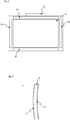
- Fig. 4 schematically illustrates a design of a semi-transparent reflector 4.
- the semi-transparent reflector 4 has a highly transparent substrate 26 with an anti-reflective layer 18 deposited on the concave surface configured for facing the image source and a partially reflective layer 10 on the convex surface configured for facing the user.
- the partially reflective layer 10 provides that the semi-transparent reflector 4 will reflect some light from the user such that a mirror image is formed.
- the anti-reflective layer 18 of the opposite surface facing the image source suppresses addition reflections such that the mirror image of the user does not also contain a strong component from this surface.
- the illustrated semi-transparent reflector 4 is designed to provide a large field of view for the light received from the user side and reflected by semi-transparent reflector towards the user.
- an image projected from a 55" screen acting as the image source and a 2400mm radius of curvature on the semi-transparent reflector provides with the user arranged about 2-3 meters from the semi-transparent reflector that the reflected image of the user is smaller than the semi-transparent reflector such that the user perceives his entire body together with the representation of the image, i.e. the virtual image.
- Fig. 5 schematically illustrates an embodiment of the system for presenting a mixed reality to a user on a large scale.
- Fig. 5A shows the system as seen from above.
- the image source 7 may be a 6000 mm wide LED screen projecting images onto the concave first surface 6 of the semi-transparent reflector 4 which may have a 9000 mm radius of curvature.
- the semi-transparent reflector has a partially reflective layer on the convex second side 8 for providing a mirror image of a user standing in front of the semi-transparent reflector.
- a motion tracker 22 is arranged to capture the movements and position of the user relative to the system and hence relative to the virtual images provided to the user.
- Fig. 5B shows the system as seen from the user side.
- the partially reflective layer on the convex second side 8 of the semi-transparent reflector 4 provides that the user 2 sees a mirror image 12 of himself when looking at the semi-transparent reflector.
Landscapes
- Physics & Mathematics (AREA)
- General Physics & Mathematics (AREA)
- Optics & Photonics (AREA)
- Engineering & Computer Science (AREA)
- Multimedia (AREA)
- Signal Processing (AREA)
- Spectroscopy & Molecular Physics (AREA)
- User Interface Of Digital Computer (AREA)
Applications Claiming Priority (1)
| Application Number | Priority Date | Filing Date | Title |
|---|---|---|---|
| DKPA201770686 | 2017-09-12 |
Publications (1)
| Publication Number | Publication Date |
|---|---|
| EP3454098A1 true EP3454098A1 (de) | 2019-03-13 |
Family
ID=60331408
Family Applications (1)
| Application Number | Title | Priority Date | Filing Date |
|---|---|---|---|
| EP17200303.0A Withdrawn EP3454098A1 (de) | 2017-09-12 | 2017-11-07 | System mit halbtransparentem reflektor für gemischte/erweiterte realität |
Country Status (1)
| Country | Link |
|---|---|
| EP (1) | EP3454098A1 (de) |
Cited By (3)
| Publication number | Priority date | Publication date | Assignee | Title |
|---|---|---|---|---|
| US11388388B2 (en) | 2020-12-01 | 2022-07-12 | Looking Glass Factory, Inc. | System and method for processing three dimensional images |
| US11415935B2 (en) | 2020-06-23 | 2022-08-16 | Looking Glass Factory, Inc. | System and method for holographic communication |
| US11754975B2 (en) | 2020-05-21 | 2023-09-12 | Looking Glass Factory, Inc. | System and method for holographic image display |
Citations (2)
| Publication number | Priority date | Publication date | Assignee | Title |
|---|---|---|---|---|
| WO2015070881A1 (en) * | 2013-11-14 | 2015-05-21 | Realfiction Aps | Display arranged for combining a physical object with one or more digital images |
| WO2016160610A1 (en) * | 2015-03-30 | 2016-10-06 | Amazon Technologies, Inc | Blended reality systems and methods |
-
2017
- 2017-11-07 EP EP17200303.0A patent/EP3454098A1/de not_active Withdrawn
Patent Citations (2)
| Publication number | Priority date | Publication date | Assignee | Title |
|---|---|---|---|---|
| WO2015070881A1 (en) * | 2013-11-14 | 2015-05-21 | Realfiction Aps | Display arranged for combining a physical object with one or more digital images |
| WO2016160610A1 (en) * | 2015-03-30 | 2016-10-06 | Amazon Technologies, Inc | Blended reality systems and methods |
Cited By (5)
| Publication number | Priority date | Publication date | Assignee | Title |
|---|---|---|---|---|
| US11754975B2 (en) | 2020-05-21 | 2023-09-12 | Looking Glass Factory, Inc. | System and method for holographic image display |
| US12204281B2 (en) | 2020-05-21 | 2025-01-21 | Looking Glass Factory, Inc. | System and method for holographic image display |
| US11415935B2 (en) | 2020-06-23 | 2022-08-16 | Looking Glass Factory, Inc. | System and method for holographic communication |
| US11388388B2 (en) | 2020-12-01 | 2022-07-12 | Looking Glass Factory, Inc. | System and method for processing three dimensional images |
| US11849102B2 (en) | 2020-12-01 | 2023-12-19 | Looking Glass Factory, Inc. | System and method for processing three dimensional images |
Similar Documents
| Publication | Publication Date | Title |
|---|---|---|
| US10573085B2 (en) | Reality mixer for mixed reality | |
| US11055920B1 (en) | Performing operations using a mirror in an artificial reality environment | |
| US10437347B2 (en) | Integrated gestural interaction and multi-user collaboration in immersive virtual reality environments | |
| US8576276B2 (en) | Head-mounted display device which provides surround video | |
| US7834846B1 (en) | Interactive video display system | |
| US11145126B1 (en) | Movement instruction using a mirror in an artificial reality environment | |
| US20180046874A1 (en) | System and method for marker based tracking | |
| WO2024253976A1 (en) | Devices, methods, and graphical user interfaces for displaying views of physical locations | |
| US20120188279A1 (en) | Multi-Sensor Proximity-Based Immersion System and Method | |
| US20120200600A1 (en) | Head and arm detection for virtual immersion systems and methods | |
| KR20160079794A (ko) | 혼합 현실 스포트라이트 | |
| KR20220099580A (ko) | 인사이드-아웃 위치, 사용자 신체 및 환경 추적을 갖는 가상 및 혼합 현실을 위한 머리 장착 디스플레이 | |
| US11036987B1 (en) | Presenting artificial reality content using a mirror | |
| US11587284B2 (en) | Virtual-world simulator | |
| US20210374982A1 (en) | Systems and Methods for Illuminating Physical Space with Shadows of Virtual Objects | |
| Sueishi et al. | Lumipen 2: Dynamic projection mapping with mirror-based robust high-speed tracking against illumination changes | |
| EP3454098A1 (de) | System mit halbtransparentem reflektor für gemischte/erweiterte realität | |
| JP6686791B2 (ja) | 映像表示方法及び映像表示システム | |
| WO2024004306A1 (ja) | 制御装置、システム、制御方法、プログラム | |
| Hieda et al. | Digital facial augmentation for interactive entertainment | |
| US20230191259A1 (en) | System and Method for Using Room-Scale Virtual Sets to Design Video Games | |
| WO2024253842A1 (en) | Devices, methods, and graphical user interfaces for real-time communication | |
| EP4720817A1 (de) | Vorrichtungen, verfahren und grafische benutzeroberflächen für echtzeitkommunikation | |
| WO2025240366A1 (en) | Methods of providing feedback based on user-to-user interaction | |
| WO2025032989A1 (ja) | 情報処理装置、情報処理方法、及びコンピュータが読み取り可能な記録媒体 |
Legal Events
| Date | Code | Title | Description |
|---|---|---|---|
| PUAI | Public reference made under article 153(3) epc to a published international application that has entered the european phase |
Free format text: ORIGINAL CODE: 0009012 |
|
| AK | Designated contracting states |
Kind code of ref document: A1 Designated state(s): AL AT BE BG CH CY CZ DE DK EE ES FI FR GB GR HR HU IE IS IT LI LT LU LV MC MK MT NL NO PL PT RO RS SE SI SK SM TR |
|
| AX | Request for extension of the european patent |
Extension state: BA ME |
|
| STAA | Information on the status of an ep patent application or granted ep patent |
Free format text: STATUS: THE APPLICATION IS DEEMED TO BE WITHDRAWN |
|
| 18D | Application deemed to be withdrawn |
Effective date: 20190914 |