EP3454354A1 - Relais - Google Patents
Relais Download PDFInfo
- Publication number
- EP3454354A1 EP3454354A1 EP17805598.4A EP17805598A EP3454354A1 EP 3454354 A1 EP3454354 A1 EP 3454354A1 EP 17805598 A EP17805598 A EP 17805598A EP 3454354 A1 EP3454354 A1 EP 3454354A1
- Authority
- EP
- European Patent Office
- Prior art keywords
- fuse
- base plate
- insulating ring
- relay according
- ring
- Prior art date
- Legal status (The legal status is an assumption and is not a legal conclusion. Google has not performed a legal analysis and makes no representation as to the accuracy of the status listed.)
- Withdrawn
Links
- 239000000919 ceramic Substances 0.000 claims description 35
- UFHFLCQGNIYNRP-UHFFFAOYSA-N Hydrogen Chemical compound [H][H] UFHFLCQGNIYNRP-UHFFFAOYSA-N 0.000 claims description 9
- 239000001257 hydrogen Substances 0.000 claims description 9
- 229910052739 hydrogen Inorganic materials 0.000 claims description 9
- 239000006004 Quartz sand Substances 0.000 claims description 8
- VYPSYNLAJGMNEJ-UHFFFAOYSA-N Silicium dioxide Chemical compound O=[Si]=O VYPSYNLAJGMNEJ-UHFFFAOYSA-N 0.000 claims description 8
- 239000002184 metal Substances 0.000 claims description 6
- 229910052751 metal Inorganic materials 0.000 claims description 6
- 239000001307 helium Substances 0.000 claims description 5
- 229910052734 helium Inorganic materials 0.000 claims description 5
- SWQJXJOGLNCZEY-UHFFFAOYSA-N helium atom Chemical compound [He] SWQJXJOGLNCZEY-UHFFFAOYSA-N 0.000 claims description 5
- 230000000694 effects Effects 0.000 abstract description 12
- 230000009471 action Effects 0.000 description 8
- XEEYBQQBJWHFJM-UHFFFAOYSA-N Iron Chemical group [Fe] XEEYBQQBJWHFJM-UHFFFAOYSA-N 0.000 description 7
- 238000009413 insulation Methods 0.000 description 6
- 239000000463 material Substances 0.000 description 5
- IJGRMHOSHXDMSA-UHFFFAOYSA-N Atomic nitrogen Chemical compound N#N IJGRMHOSHXDMSA-UHFFFAOYSA-N 0.000 description 4
- 238000009434 installation Methods 0.000 description 4
- 238000005476 soldering Methods 0.000 description 3
- 238000005219 brazing Methods 0.000 description 2
- 230000003139 buffering effect Effects 0.000 description 2
- 230000015556 catabolic process Effects 0.000 description 2
- 239000007789 gas Substances 0.000 description 2
- 238000012423 maintenance Methods 0.000 description 2
- 230000007246 mechanism Effects 0.000 description 2
- 238000000034 method Methods 0.000 description 2
- 229910052757 nitrogen Inorganic materials 0.000 description 2
- 229910010293 ceramic material Inorganic materials 0.000 description 1
- 239000004020 conductor Substances 0.000 description 1
- 238000001816 cooling Methods 0.000 description 1
- 239000000428 dust Substances 0.000 description 1
- 230000002708 enhancing effect Effects 0.000 description 1
- 230000004927 fusion Effects 0.000 description 1
- 239000011810 insulating material Substances 0.000 description 1
- 238000002955 isolation Methods 0.000 description 1
- 238000012986 modification Methods 0.000 description 1
- 230000004048 modification Effects 0.000 description 1
- 230000002093 peripheral effect Effects 0.000 description 1
- 230000008569 process Effects 0.000 description 1
- 229910000679 solder Inorganic materials 0.000 description 1
- 239000000126 substance Substances 0.000 description 1
Images

Classifications
-
- H—ELECTRICITY
- H01—ELECTRIC ELEMENTS
- H01H—ELECTRIC SWITCHES; RELAYS; SELECTORS; EMERGENCY PROTECTIVE DEVICES
- H01H50/00—Details of electromagnetic relays
- H01H50/02—Bases; Casings; Covers
-
- H—ELECTRICITY
- H01—ELECTRIC ELEMENTS
- H01H—ELECTRIC SWITCHES; RELAYS; SELECTORS; EMERGENCY PROTECTIVE DEVICES
- H01H85/00—Protective devices in which the current flows through a part of fusible material and this current is interrupted by displacement of the fusible material when this current becomes excessive
- H01H85/02—Details
- H01H85/0241—Structural association of a fuse and another component or apparatus
-
- H—ELECTRICITY
- H01—ELECTRIC ELEMENTS
- H01H—ELECTRIC SWITCHES; RELAYS; SELECTORS; EMERGENCY PROTECTIVE DEVICES
- H01H50/00—Details of electromagnetic relays
- H01H50/02—Bases; Casings; Covers
- H01H50/021—Bases; Casings; Covers structurally combining a relay and an electronic component, e.g. varistor, RC circuit
-
- H—ELECTRICITY
- H01—ELECTRIC ELEMENTS
- H01H—ELECTRIC SWITCHES; RELAYS; SELECTORS; EMERGENCY PROTECTIVE DEVICES
- H01H50/00—Details of electromagnetic relays
- H01H50/02—Bases; Casings; Covers
- H01H50/023—Details concerning sealing, e.g. sealing casing with resin
-
- H—ELECTRICITY
- H01—ELECTRIC ELEMENTS
- H01H—ELECTRIC SWITCHES; RELAYS; SELECTORS; EMERGENCY PROTECTIVE DEVICES
- H01H50/00—Details of electromagnetic relays
- H01H50/14—Terminal arrangements
-
- H—ELECTRICITY
- H01—ELECTRIC ELEMENTS
- H01H—ELECTRIC SWITCHES; RELAYS; SELECTORS; EMERGENCY PROTECTIVE DEVICES
- H01H50/00—Details of electromagnetic relays
- H01H50/54—Contact arrangements
-
- H—ELECTRICITY
- H01—ELECTRIC ELEMENTS
- H01H—ELECTRIC SWITCHES; RELAYS; SELECTORS; EMERGENCY PROTECTIVE DEVICES
- H01H9/00—Details of switching devices, not covered by groups H01H1/00 - H01H7/00
- H01H9/10—Adaptation for built-in fuses
-
- H—ELECTRICITY
- H01—ELECTRIC ELEMENTS
- H01H—ELECTRIC SWITCHES; RELAYS; SELECTORS; EMERGENCY PROTECTIVE DEVICES
- H01H50/00—Details of electromagnetic relays
- H01H50/02—Bases; Casings; Covers
- H01H50/023—Details concerning sealing, e.g. sealing casing with resin
- H01H2050/025—Details concerning sealing, e.g. sealing casing with resin containing inert or dielectric gasses, e.g. SF6, for arc prevention or arc extinction
-
- H—ELECTRICITY
- H01—ELECTRIC ELEMENTS
- H01H—ELECTRIC SWITCHES; RELAYS; SELECTORS; EMERGENCY PROTECTIVE DEVICES
- H01H50/00—Details of electromagnetic relays
- H01H50/54—Contact arrangements
- H01H50/546—Contact arrangements for contactors having bridging contacts
-
- H—ELECTRICITY
- H01—ELECTRIC ELEMENTS
- H01H—ELECTRIC SWITCHES; RELAYS; SELECTORS; EMERGENCY PROTECTIVE DEVICES
- H01H9/00—Details of switching devices, not covered by groups H01H1/00 - H01H7/00
- H01H9/30—Means for extinguishing or preventing arc between current-carrying parts
- H01H9/44—Means for extinguishing or preventing arc between current-carrying parts using blow-out magnet
- H01H9/443—Means for extinguishing or preventing arc between current-carrying parts using blow-out magnet using permanent magnets
Definitions
- the present disclosure relates to a field of electrical equipment, and in particular, to a relay.
- a short circuit may occur during the use of electrical equipment.
- the relay has no overload protection device. When the relay is turned on, once a load current is too large or a short circuit occurs in a circuit, it is easy to cause a fire, which causes the product to lose functions and causes a risk.
- the above relay has no arc-extinguishing device, which resulting in long arcing time and short product lifetime.
- the one object of the present disclosure is to provide a relay for reducing or avoiding a safety hazard due to current overload or short circuit.
- a relay comprising: a housing, on which at least one stationary contact group is provided, wherein the stationary contact group includes two stationary contacts insulated from each other, at least one stationary contact in the stationary contact group includes an upper terminal and a lower contact are included, and the upper terminal and the lower contact are isolated from each other and electrically connected by a fuse; a base plate, which is provided in the housing and can switch between an on position and an off position, wherein the base plate, when being in the on position, contacts the stationary contact group for the electrical conduction of the two stationary contacts in the stationary contact group, and the base plate, when being in the off position, is isolated from the stationary contact group for disconnecting the electrical conduction of the two stationary contacts in the stationary contact group; and a driving device, connected to the base plate so as to drive the base plate to switch between the on position and the off position.
- the base plate being in the on position means that the base plate being in the conductive position; and the base plate being in the off position means that the base plate is being in the disconnected position.
- the fuse has the effects of overload protection and short circuit protection to enhance the safety of a circuit system having the relay and avoid a fire disaster or the like due to the over-current or short circuit.
- an insulating ring is connected between the upper terminal and the lower contact, wherein the upper terminal encloses the upper end of the insulating ring and the lower contact encloses the lower end of the insulating ring, and at least part of the fuse is disposed inside the insulating ring.
- the fuse is isolated from the inner circumferential surface of the insulating ring by a preset distance.
- the insulating ring is a ceramic ring.
- the insulating ring is filled with quartz sand.
- the insulating ring has a metal layer respectively on the upper end surface and the lower end surface.
- the fuse has a cylinder body, and each of the edges of the upper end and the lower end of the fuse has an outwardly extending flange, and the flange extends to the corresponding end surface of the insulating ring.
- the body of the fuse is located in the insulating ring, and an annular cavity surrounding the fuse is defined between the body part of the fuse and the inner circumferential surface of the insulating ring.
- the fuse has a fusing part, the fusing part being located in the middle position of the body part in the axial direction.
- the upper terminal is respectively soldered to the fuse and the insulating ring
- the lower contacts are respectively soldered to the fuse and the insulating ring.
- a first connecting ring is provided on the lower surface of the upper terminal, and the first connecting ring is respectively soldered to the upper end surface of the insulating ring and the upper end surface of the fuse, while a second connecting ring is disposed on the upper surface of the lower contact, and the second connecting ring is respectively soldered to the lower end surface of the insulating ring and the lower end of the fuse.
- the axes of the first connecting ring and the second connecting ring extend in the up and down direction, and the wall thickness of the first connecting ring and the second connecting ring is in a range of 1 mm to 5 mm.
- the relay further comprises a magnet disposed circumferentially.
- the housing comprises: a ceramic casing, the bottom of which is open; a pallet which is disposed under the ceramic casing so as to enclose the bottom of the ceramic casing; and a connecting platform which is respectively connected to the ceramic casing and the pallet.
- the housing is filled with hydrogen or helium.
- the driving device comprises: a push rod, the upper end of the push rod being connected to the base plate and lower end projecting downwardly from the housing, the upper end of the push rod passing through the base plate and being connected to a snap spring and a gasket, wherein the snap spring is clamped on the push rod, and the gasket is positioned between the snap spring and the connecting part; and a buffer spring, the buffer spring being sleeved outside the push rod, wherein the upper end of the buffer spring presses against the base plate, and the lower end of the buffer spring presses against the push rod or the bottom of the housing.
- the circumferential sheath of the upper end of the push rod is provided with an insulating sheath which isolates the push rod from the base plate, and the upper end of the buffer spring presses against the insulating sheath.
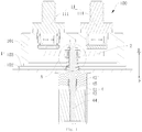
- the relay 100 in an embodiment of the present disclosure, comprising: a housing 1, a base plate 2, and a driving device 4.
- the housing 1 is provided with at least one stationary contact group 11; the stationary contact group 11 includes two mutually insulated stationary contacts 111; and at least one stationary contact 111 in the stationary contact group 11 includes an upper terminal 1111 and a lower contact 1112.
- the upper terminal 1111 and the lower contact 1112 are isolated from each other for insulation, and the upper terminal 1111 and the lower contact 1112 are connected together by a fuse 3, thus electrical conduction between the upper terminal 1111 and the lower contact 1112 is realized by the fuse 3. That is, the upper terminal 1111 and the lower contact 1112 are insulated from each other when the fuse 3 is not connected, and then the upper terminal 1111 and the lower contact 1112 are electrically connected by the fuse 3.
- the base plate 2 is disposed in the housing 1, and can switch between an on position and an off position.
- the base plate 2 is in contact with the two stationary contacts 111 in the stationary contact group 11 for electrical conduction of the two stationary contacts 111 in the stationary contact group 11.
- the base plate 2 is isolated from the two stationary contacts 111 in the stationary contact group 11 so as to disconnect the electrical conduction of the two stationary contacts 111 in the stationary contact group 11.
- the driving device 4 is connected to the base plate 2 so as to drive the base plate 2 to switch between the on position and the off position.
- the fuse 3 in the stationary contact 111 is disconnected, thereby disconnecting the electrical connection among the plurality of the stationary contacts 111, and causing the relay 100 be in an off state. Consequently, the circuit is disconnected.
- the relay 100 in the embodiment of the present disclosure due to the fuse 3 disposed in the stationary contact 111, the effects of overload protection and short circuit protection are realized by the fuse 3, so as to improve the safety of a circuit system having the relay 100, and avoid fire disaster or the like caused by the over current or short circuit.
- the fuse 3 is used for overload protection, effectively avoiding a risk caused by the current overload or short circuit.
- the fuse 3 is integrated into the stationary contact 111 to facilitate replacement of the fuse 3 and maintenance of the relay 100, as well as the use and maintenance of the relay 100 and the circuit system having the relay 100.
- the base plate 2 of the present disclosure may further be provided with at least one movable contact group corresponding to the stationary contact group 11, and each movable contact group includes two electrically conducted movable contacts.
- each movable contact group includes two electrically conducted movable contacts.
- the base plate 3 When the base plate 3 is in the on position, the movable contact group 21 is in contact with the stationary contact group 11, and the two stationary contacts 111 in the stationary contact group 11 are electrically conducted.
- the base plate 2 is in the off position, the movable contact group is isolated from the stationary contact group 11, and two stationary contacts 111 in the stationary contact group 11 disconnect the electrical conduction.
- At least one stationary contact group may be disposed on the housing 1 in the present disclosure.
- the at least one stationary contact 111 in the at least one stationary contact group 11 includes the upper terminal 1111 and the lower contact 1112, and the upper terminal 1111 and the lower contact 1112 are conducted by the fuse.
- the number of the stationary contact group 11 is one, and one of the two stationary contacts 111 in the stationary contact group 11 includes the upper terminal 1111 and the lower contact 1112, or, each of the stationary contacts 111 in the stationary contact group 11 includes the upper terminal 1111 and the lower contact 1112.
- the number of the stationary contact group 11 is two, and one or each of the stationary contacts 111 in one stationary contact group 11 includes the upper terminal 1111 and the lower contact 1112, while two stationary contacts 111 in the other stationary contact group 11 do not include the upper terminal 1111 and the lower contact 1112.
- the number of the stationary contact group 11 is two, and each of the stationary contacts 111 in each of the two stationary contact group 11 includes the upper terminal 1111 and the lower contact 1112.
- the number of the stationary contact group 11 is not limited in the present disclosure.
- the number of the stationary contact group 11 may be three, four, or any other number.
- both of the upper terminal 1111 and the lower contact 1112 may be connected to the housing 1 so that the upper terminal 1111 and the lower contact 1112 are fixed relative to each other, and the upper terminal 1111 is isolated from the lower contact 1112 for mutual insulation.
- the upper terminal 1111 and the lower contact 1112 are electrically connected by the fuse 3.
- a cavity may also be defined between the upper terminal 1111 and the lower contact 1112 by means of the housing 1.
- a connection structure may also be provided between the upper terminal 1111 and the lower contact 1112, so that the upper terminal 1111 and the lower contact 1112 are fixed relative to each other, and the upper terminal 1111 is isolated from the lower contact 1112 for the insulation.
- the upper terminal 1111 is electrically connected to the lower contact 1112 by the fuse 3.
- an insulating ring 1113 is connected between the upper terminal 1111 and the lower contact 1112.
- the upper terminal 1111 encloses the upper end of the insulating ring 1113
- the lower contact 1112 encloses the lower end of the insulating ring 1113. Both ends are enclosed by the upper terminal 1111 and the lower contact 1112, so as to define an enclosed cavity in the insulating ring 1113.
- At least part of the fuse 3 is provided inside the insulating ring 1113. That is, the fuse 3 is accommodated by the insulating ring 1113, thereby forming a protection effect to the fuse 3.
- the fuse 3 in the fusing is prevented from being scattered to cause the safety hazard, thus improving the safety performance of the relay 100.
- the fuse 3 is isolated from the inner circumferential surface of the insulating ring 1113 by a preset distance, so as to avoid the fusing difficulty of the fuse 3 due to the bonding of the fuse 3 to the inner circumferential surface of the insulating ring 1113.
- the fuse 3 has a fusing part 32 isolated from the inner circumferential surface of the insulating ring 1113.
- the insulating ring 1113 is a ceramic ring.
- other materials such as plastic or the like may also be used to make the insulating ring 1113.
- the insulating ring 1113 is filled with quartz sand (not shown). With the arc extinguishing by the quartz sand, the safety hazard caused by generating arc is avoided and the impact on product safety due to long arcing time when the fuse 3 is in fusing is reduced.
- a metal layer is provided on both the upper end surface and the lower end surface of the insulating ring 1113.
- the upper and lower ends of the fuse 3 may be soldered to the corresponding metal layer so as to realize the installation of the fuse 3, resulting in convenient installation and high structural strength of the fuse 3. Moreover, the conduction effect between the upper terminal 1111 and the fuse 3 and the conduction effect between the lower contact 1112 and the fuse 3 may also be enhanced by the metal layer.
- the fuse 3 has a cylindrical body part 33, and each of the edges of the upper and lower ends of the fuse 3 has an outwardly extending flange 31, and the flange 31 extends to the corresponding end surface of the insulating ring 1113. That is, both ends of the fuse 3 are connected to the end surfaces of the insulating ring 1113, and the middle part of the fuse 3 is in the insulating ring 1113.
- the fuse 3 is easy to be electrically connected when the upper terminal 1111 is at the upper end of the enclosed insulating ring 1113, while the fuse 3 is easy to be electrically connected when the lower contact 1112 is at the lower end of the enclosed insulating ring 1113, thus improving the installation efficiency of the relay 100.
- the upper terminal 1111 and the lower contact 1112 may keep electrical connection with the fuse 3.
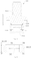
- the body part 33 of the fuse 3 is disposed in the insulating ring 1113, and the body part 33 of the fuse 3 and the inner circumferential surface of the insulating ring 1113 are apart from each other, and a annular cavity 1114 is defined between the body part 33 of the fuse 3 and the inner circumferential surface of the insulating ring 1113, wherein the annular cavity 1114 surrounds the body part 33 of the fuse 3. Therefore, the efficient isolation of the body part 33 of the fuse 3 from the insulating ring 1113 is realized by the annular cavity 1114, so that the fuse 3 may be in fusing smoothly.
- the fusing part 32 of the fuse is in the middle position of the body part 33 of the fuse 3 in the axial direction (see the up and down direction in figure 5 ) to further facilitate the fusing of the fuse.
- the fuse 3 is soldered to the insulating ring 1113, so as to stably install the fusion 3 on the insulating ring 1113 by means of soldering, thus improving the stability and safety of the relay 100.
- the upper terminal 1111 and the lower contact 1112 may be installed conveniently, thus improving the assembly efficiency of the relay 100.
- the upper terminal 1111 are soldered respectively to the fuse 3 and the insulating ring 1113
- the lower contact 1112 is soldered respectively to the fuse 3 and the insulating ring 1113.
- the lower surface of the upper terminal 1111 in the present disclosure is provided with a first connecting ring 1115, and the first connecting ring 1115 is respectively soldered to the upper end surface of the insulating ring 1113 and the upper end of the fuse 3.
- the upper surface of the lower contact 1112 is provided with a second connecting ring 1116, and the second connecting ring 1116 is respectively soldered to the lower end surface of the insulating ring 1113 and the lower end of the fuse 3.
- the axes of the first connecting ring 1115 and the second connecting ring 1116 extend in the up and down direction, and the wall thickness of the second connecting ring 1116 and the first connecting ring 1115 is in the range of 1 mm to 5 mm.
- the relay 100 further comprises a magnet (not shown) disposed in a circumferential direction. Under the action of the magnetic field of the magnet, the arc is elongated, and the arc is divided into segments by arc chute at this time, thereby having the effect of arc extinguishing by means of the magnet.
- the housing 1 comprises: a ceramic casing 101, a pallet 102, and a connecting platform 103, wherein the bottom of the ceramic casing 101 is open, and the pallet 102 is disposed under the ceramic casing 101 so as to enclose the bottom of the ceramic casing 101, and the connecting platform 103 is respectively connected to the ceramic casing 101 and the pallet 102.
- a sealed cavity may be formed in the ceramic casing 101, so as to avoid the dust and the like from entering the housing 1, and the electrical safety may be improved at the same time.
- the housing 1 is divided into the ceramic casing 101, the pallet 102 and the connecting platform 103, which facilitates the installation of elements such as the base plate 2, and the driving device 4.
- the ceramic has relatively good strength, high chemical stability and thermal stability, and is also a poor electrical conductor. Therefore, in the present disclosure, the ceramic casing is utilized. The insulation performance of the housing 1 is improved to reduce the safety hazard.
- the housing 1 may be other insulating materials.
- the specific material of the housing 1 is not limited. In practice, the material may be adaptively selected.
- the housing 1 is filled with hydrogen or helium.
- hydrogen or helium an arc extinguishing gas layer may be formed, and during a switching procedure of the relay 100, the arc is quickly extinguished by the hydrogen or helium, thereby reducing the safety hazard.
- the driving device 4 is connected to the bottom of the housing 1, and the driving device 4 comprises a push rod 44 and a buffer spring 47.
- the upper end of the push rod 44 is connected to the base plate 2 and the lower end projects downwardly from the housing 1.
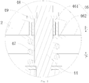
- the upper end of the push rod 44 passes through the base plate 2 and is connected to a snap spring 48 and a gasket 49.
- the snap spring 48 is clamped on the push rod 44 and the gasket 49 is between the snap spring 48 and the connection part 202.
- the buffer spring 47 is sleeved outside of the push rod 44 and the upper end of the buffer spring 47 presses against the base plate 2, while the lower end of the buffer spring 47 presses against the push rod 44 or the bottom of the housing 1. With the matching of the buffer spring 47 and the snap spring 48, etc., the buffering of the base plate 2 is realized. During the on and off process of the relay, rigid contact between the stationary contact group 11 and the movable contact group 21 may be avoided by buffering, thereby improving the stability of the relay and reducing the noise of the relay.
- the base plate 2 is provided with a sheath 46.
- the sheath 46 may be used to isolate the base plate 2 from the push rod 44, thereby avoiding damage and breakdown of elements at the low voltage side. Therefore, the quality of the relay 100 and the safety of the use are improved.
- the insulating sheath 46 is sleeved on the peripheral of the upper end of the push rod 44 so as to isolate the push rod 44 from the base plate 2, and the upper end of the buffer spring 47 presses against the insulating sheath 46, thereby electrically isolating the buffer spring 47 from the base plate 2.
- the base plate 2 is provided with a through hole, and the insulating sheath 46 may be disposed inside the through hole, and the insulating sheath 46 may be sleeved outside the push rod 44. Therefore, the push rod 44 may be protected to a certain extent, so the accuracy and smoothness of the action of the push rod 44 may be ensured, thereby improving the performance of the use of the relay 100.
- the driving device 4 further comprises a sleeve 41, a limiting post 42, an iron core 43 and a reset spring 45.
- the upper end of the sleeve 41 is connected to the housing 1, and the limiting post 42 is disposed on the upper part of the sleeve 41 and is connected to the housing 1; the iron core 43 is disposed on the lower part of the sleeve 41 and is able to move up and down; one end of the push rod 44 is connected to the iron core 43 and the other end is connected to the base plate 2; and the reset spring 45 is sleeved outside the push rod 44 and both ends respectively press against the iron core 43 and the limiting post 42. Therefore, the on and off of the relay 100 is easily controlled by the driving device 44, thus the performance of the use of the relay 100 may be improved to a certain extent.
- the upper end of the push rod 44 (for example, the upper end of the push rod 44 in figure 1 or 2 ) may pass through the through hole in the base plate 2.
- the end of the push rod 44 passing through the through hole is provided with the snap spring 48 and gasket 49.
- the gasket 49 can reduce the force of the snap spring 48 and may prevent the snap spring 48 from falling off. In this way, the operational stability of the relay 100 may be further improved.
- the buffer spring 47 is sleeved outside of the push rod 44 (for example, the side distanced from the push rod 44 in figures 1 and 2 ), and the buffer spring 47 may be used to constantly push the push rod 44 so that the base plate 2 presses against the snap spring 48. Therefore, the action of the push rod 44 may be smoother, and the action accuracy of the relay 100 may also be improved.
- One end of the buffer spring 47 is connected to the base plate 2, and the other end of the buffer spring 47 is connected to one of the push rod 44 and the housing.
- a first end of the buffer spring 47 is connected to the base plate 2 (for example, the upper end of the buffer spring 47 in figure 2 ), and a second end of the buffer spring 47 (for example, the lower end of the buffer spring 47 in figure 1 ) is connected to the base plate 2; alternatively, the first end of the buffer spring 47 is connected to the base plate 2 (for example, the upper end of the buffer spring 47 in figure 2 ), and the second end of the buffer spring 47 (for example, the lower end of the buffer spring 47 in figure 1 ) is connected to the housing 1.
- the upper end of the buffer spring 47 is connected to the housing 1 and the lower end is connected to the base plate 2. At this time, the buffer spring should often be in a stretched state. The operation smoothness of the relay 100 may be enhanced, which satisfies the requirements of the user better.
- the insulating sheath 46 in the present disclosure comprises an upper insulating cover 461 and a lower insulating cover 462.
- the upper insulating cover 461 comprises a first cylindrical body and a first flange at the upper end of the first cylindrical body
- the lower insulating cover 462 comprises a second cylindrical body and a second flange at the lower end of the second cylindrical body.
- the first cylindrical body of the upper insulating cover is inserted into the through hole, and the first flange presses against the upper surface of the base plate, while the second cylindrical body of the lower insulating cover is inserted into the through hole, and the second flange presses against the lower surface of the base plate.
- the first cylindrical body is inserted into the second cylindrical body, and the first cylindrical body and the second cylindrical body are inserted into the through hole together.
- the relay 100 has over current protection function of the circuit, and can realize the function of the circuit breaker.
- Short circuit protection structure consists of the upper terminal 1111, the ceramic ring (i.e., the insulating ring 1113), the fuse 3, and the lower contact 1112.
- the short circuit protection structure may be assembled as follows: metalizing the upper and lower surfaces of the ceramic ring; brazing the fuse 3 and the ceramic ring after the fuse 3 is folded into two; and then brazing the ceramic ring and the lower contact 1112; and filling the quartz sand into the ceramic ring. That is, the lower contact 1112, the ceramic ring and the upper terminal 1111 constitute the stationary contact 111 having the fuse 3 as shown in figure 4 .
- the fuse 3 has function of the overload protection, and the quartz sand has function of the arc extinguishing when the fuse 3 is in fusing, and the ceramic ring has the functions of supporting, fixing, preventing splashing when the fuse 3 is in fusing, and insulation of the upper and lower contacts 1112 after the fuse 3 is in fusing.
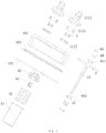
- the fuse 3 is soldered to the ceramic ring; secondly, the lower contact 1112 of the upper terminal 1111 is soldered to the ceramic ring to form the stationary contact 111; and then the stationary contact 111 is soldered to the ceramic casing 101 so as to form two sets of safety mechanisms; the buffer spring, lower insulating cover, base plate, upper insulating cover are assembled on the push rod in turn; and the gasket is assembled at last, and then snap spring is used for fixing.
- the driving device 4 After assembling the above components, the driving device 4 is installed.
- the pallet 102, limiting post 42, reset spring 45 are installed on the push rod in turn, and the iron core 43 and the push rod are fixed by means of laser soldering or screwing.
- the relay As shown in figure 1 , the relay is in the off state.
- the driving device 4 starts working, the base plate contacts the stationary contact 111 having the fuse 3, and load current pass through the fuse 3.
- the fuse is in fusing so as to have the protection effect.
- the external magnet of the relay 100 hydrogen in the cavity and the quartz sand in the ceramic ring, the arc can be extinguished quickly.
- Two sets of the safety stationary contacts 111 act at the same time, so the protection effect is gained more safely.
- the upper insulating cover and the lower insulating cover isolate the push rod from the high voltage load end, thereby insulating the high and low voltage, and preventing the damage to the elements at the low voltage end and the breakdown phenomenon.
- the quality of the product and the safety are improved.
- the fuse 3 is used for the overload protection, which effectively prevents the risks caused by the current overload or short circuit. Meanwhile, with the combined action of the external magnet of the relay 100, the hydrogen in the cavity and the quartz sand in the ceramic ring, the impacts to the product safety caused by the long arcing time are reduced when the fuse 3 is in fusing. The two sets of the safety stationary contacts 111 act at the same time. Thus, the fusing accuracy of the product and the safety of the use are improved. In contrast, in the present disclosure, the fuse 3 and the relay 100 are combined, which saves the whole overall use space and cost. It can effectively improve the quality and safety of the product by using the arc extinguishing mechanism of the relay 100 on the fuse 3.
- orientation or position relationships indicated by the terms “central”, “longitudinal”, “transverse”, “length”, “width”, “thickness”, “on”, “under”, “front”, “rear”, “left”, “right”, “vertical”, “horizontal”, “top”, “bottom”, “inside”, “outside”, “clockwise”, “counterclockwise”, “axial direction”, “radial”, “circumferential”, and the like are orientation or position relationships based on what is shown in the accompanying drawings, and are only used to facilitate description of the present invention and simplify the description, rather than to indicate or imply that the device or component must be in specific orientation or disposed and operated in the specific orientation, and therefore cannot be understood as a limitation to the present invention.
- first and second are only used for description purpose and cannot be understood to indicate or imply relative importance or implicitly indicate the quantity of technical features. Therefore, features that are defined by “first” and “second” may explicitly or implicitly include one or more features. In the description of the present disclosure, the meaning of "a plurality of” is two or more, for example, two, three and the like, unless otherwise clearly and specifically limited.
- the terms “mounted,” “connected,” “coupled”, “fixed” and the like are construed broadly and encompass such as fixed or detachable or integral connections, mechanical or electrical connections, can also be direct connections and indirect connections by using an intermediate medium, and can also be inner connections of two components or mutual effect relationships of two components.
- the specific meanings of the foregoing terms in the present disclosure can be understood by those skilled in the art according to the specific cases.
- first and second features when a first feature is “on” or “under” a second feature, the first and second features may be in direct contact, or the first and second features are in indirect contact by using an intermediate medium. Moreover, when the first feature is “on” or “above” the second feature, the first feature may be right above the second feature or obliquely above the second feature, or it merely represents that the first feature is horizontally higher than the second feature. When the first feature is "under” or “below” the second feature, the first feature may be right below the second feature or obliquely below the second feature, or it merely represents that the first feature is horizontally lower than second feature.
Landscapes
- Physics & Mathematics (AREA)
- Electromagnetism (AREA)
- Engineering & Computer Science (AREA)
- Power Engineering (AREA)
- Fuses (AREA)
Applications Claiming Priority (2)
| Application Number | Priority Date | Filing Date | Title |
|---|---|---|---|
| CN201610379158.3A CN107452550B (zh) | 2016-05-31 | 2016-05-31 | 继电器 |
| PCT/CN2017/082905 WO2017206653A1 (fr) | 2016-05-31 | 2017-05-03 | Relais |
Publications (2)
| Publication Number | Publication Date |
|---|---|
| EP3454354A1 true EP3454354A1 (fr) | 2019-03-13 |
| EP3454354A4 EP3454354A4 (fr) | 2019-05-01 |
Family
ID=60479656
Family Applications (1)
| Application Number | Title | Priority Date | Filing Date |
|---|---|---|---|
| EP17805598.4A Withdrawn EP3454354A4 (fr) | 2016-05-31 | 2017-05-03 | Relais |
Country Status (6)
| Country | Link |
|---|---|
| US (1) | US11056305B2 (fr) |
| EP (1) | EP3454354A4 (fr) |
| JP (1) | JP2019517715A (fr) |
| KR (1) | KR20180132920A (fr) |
| CN (1) | CN107452550B (fr) |
| WO (1) | WO2017206653A1 (fr) |
Cited By (3)
| Publication number | Priority date | Publication date | Assignee | Title |
|---|---|---|---|---|
| DE102018213102A1 (de) * | 2018-08-06 | 2020-02-06 | Audi Ag | Schütz für ein Fahrzeug |
| CN111029219A (zh) * | 2019-12-30 | 2020-04-17 | 珠海广通汽车有限公司 | 一种安全通断控制组件和pdu控制器 |
| WO2023061862A1 (fr) * | 2021-10-14 | 2023-04-20 | Schott Ag | Douille comprenant une borne de connexion, et boîtier et relais comprenant une telle douille |
Families Citing this family (15)
| Publication number | Priority date | Publication date | Assignee | Title |
|---|---|---|---|---|
| CN109036969B (zh) * | 2018-08-07 | 2019-10-08 | 速达(泰州)新能源有限公司 | 一种防止过载粘结的继电器 |
| CN110600348A (zh) * | 2019-10-14 | 2019-12-20 | 中汇瑞德电子(芜湖)有限公司 | 灭弧室 |
| CN211980527U (zh) * | 2020-05-29 | 2020-11-20 | 比亚迪股份有限公司 | 继电器 |
| CN212810187U (zh) * | 2020-06-09 | 2021-03-26 | 比亚迪股份有限公司 | 继电器 |
| KR102256432B1 (ko) * | 2020-11-25 | 2021-05-26 | 주식회사 와이엠텍 | 절연된 가동 접점을 포함하는 접점 장치 |
| CN112635246A (zh) * | 2020-12-21 | 2021-04-09 | 东莞市中汇瑞德电子股份有限公司 | 一种具有可靠密封结构的高压直流继电器 |
| US12308189B2 (en) | 2021-01-21 | 2025-05-20 | Gigavac, Llc | Switching device with ceramic/glass eyelets |
| CN112928000B (zh) * | 2021-01-22 | 2023-07-25 | 廊坊北熔电气股份有限公司 | 一种具有卸扣结构的高压熔断器 |
| CN114121555B (zh) | 2021-11-17 | 2025-09-09 | 厦门宏发电力电器有限公司 | 一种可提高绝缘能力的高压直流继电器 |
| CN115383238A (zh) * | 2022-08-11 | 2022-11-25 | 浙江福达合金材料科技有限公司 | 一种接触器动触头组件的焊接装置及方法 |
| CN115985719A (zh) * | 2022-12-13 | 2023-04-18 | 立讯智造科技(常熟)有限公司 | 高压直流继电器 |
| EP4485490A1 (fr) * | 2023-06-27 | 2025-01-01 | TE Connectivity Solutions GmbH | Dispositif de commutation avec extinction d'arc améliorée |
| WO2025031384A1 (fr) * | 2023-08-07 | 2025-02-13 | 厦门宏发电力电器有限公司 | Structure d'isolation d'arc, unité de contact et relais |
| CN221861543U (zh) * | 2024-02-07 | 2024-10-18 | 厦门宏发电力电器有限公司 | 继电器 |
| US20260011518A1 (en) * | 2024-07-05 | 2026-01-08 | Te Connectivity Solutions Gmbh | Contactor with Anti-Levitation Mechanism |
Family Cites Families (10)
| Publication number | Priority date | Publication date | Assignee | Title |
|---|---|---|---|---|
| DE10113733B4 (de) * | 2001-03-21 | 2010-12-16 | Robert Bosch Gmbh | Schraubkontaktvorrichtung insbesondere für Kraftfahrzeug-Starter |
| JP2002324478A (ja) * | 2001-04-25 | 2002-11-08 | Sumitomo Wiring Syst Ltd | ヒューズ付電磁リレー |
| JP4161066B2 (ja) * | 2002-07-16 | 2008-10-08 | 三菱電機株式会社 | 補助回転式スタータ |
| JP2005005243A (ja) * | 2003-05-16 | 2005-01-06 | Sumitomo Electric Ind Ltd | 直流リレー |
| JP4111219B2 (ja) * | 2005-12-07 | 2008-07-02 | 三菱電機株式会社 | スタータ |
| WO2009116493A1 (fr) * | 2008-03-19 | 2009-09-24 | パナソニック電工株式会社 | Dispositif de contact |
| JP4760959B2 (ja) * | 2009-05-28 | 2011-08-31 | 株式会社デンソー | 電磁継電器 |
| JP5569590B2 (ja) | 2011-02-02 | 2014-08-13 | 日本精工株式会社 | スラストころ軸受 |
| CN204927190U (zh) * | 2015-08-31 | 2015-12-30 | 惠州比亚迪实业有限公司 | 一种继电器 |
| KR101985433B1 (ko) * | 2015-08-31 | 2019-06-04 | 비와이디 컴퍼니 리미티드 | 릴레이 |
-
2016
- 2016-05-31 CN CN201610379158.3A patent/CN107452550B/zh active Active
-
2017
- 2017-05-03 EP EP17805598.4A patent/EP3454354A4/fr not_active Withdrawn
- 2017-05-03 WO PCT/CN2017/082905 patent/WO2017206653A1/fr not_active Ceased
- 2017-05-03 KR KR1020187033653A patent/KR20180132920A/ko not_active Withdrawn
- 2017-05-03 US US16/303,621 patent/US11056305B2/en active Active
- 2017-05-03 JP JP2018562346A patent/JP2019517715A/ja not_active Withdrawn
Cited By (3)
| Publication number | Priority date | Publication date | Assignee | Title |
|---|---|---|---|---|
| DE102018213102A1 (de) * | 2018-08-06 | 2020-02-06 | Audi Ag | Schütz für ein Fahrzeug |
| CN111029219A (zh) * | 2019-12-30 | 2020-04-17 | 珠海广通汽车有限公司 | 一种安全通断控制组件和pdu控制器 |
| WO2023061862A1 (fr) * | 2021-10-14 | 2023-04-20 | Schott Ag | Douille comprenant une borne de connexion, et boîtier et relais comprenant une telle douille |
Also Published As
| Publication number | Publication date |
|---|---|
| US11056305B2 (en) | 2021-07-06 |
| US20200321178A1 (en) | 2020-10-08 |
| CN107452550B (zh) | 2019-07-26 |
| EP3454354A4 (fr) | 2019-05-01 |
| KR20180132920A (ko) | 2018-12-12 |
| CN107452550A (zh) | 2017-12-08 |
| WO2017206653A1 (fr) | 2017-12-07 |
| JP2019517715A (ja) | 2019-06-24 |
Similar Documents
| Publication | Publication Date | Title |
|---|---|---|
| US11056305B2 (en) | Relay | |
| EP3345203B1 (fr) | Relais | |
| EP0801798B1 (fr) | Dispositif a relais etanche | |
| CN205723344U (zh) | 继电器 | |
| CN205723356U (zh) | 继电器 | |
| US10256059B2 (en) | Magnetic switch | |
| JP2012089494A (ja) | 真空インタラプタの接点アセンブリ | |
| CN205789760U (zh) | 继电器 | |
| CN115552561A (zh) | 开关装置 | |
| CN107204250A (zh) | 继电器 | |
| US2343323A (en) | Electric switch | |
| CN205984821U (zh) | 继电器 | |
| WO2017206652A1 (fr) | Relais | |
| EP4300526B1 (fr) | Pôle d'interrupteur à vide et son dispositif électrique associé | |
| CN107452552B (zh) | 继电器 | |
| CN206040548U (zh) | 继电器 | |
| CN205789733U (zh) | 继电器 | |
| CN107452549B (zh) | 继电器 | |
| CN107452551A (zh) | 继电器 | |
| KR20130120221A (ko) | 진공 차단기의 가동 접촉자의 편심 방지 구조 | |
| CN107452556B (zh) | 继电器 | |
| CN107452557B (zh) | 继电器 | |
| CN205789564U (zh) | 继电器 | |
| JP3502555B2 (ja) | 真空バルブ、真空遮断器および受配電装置 | |
| CN112216553A (zh) | 一种改良式真空灭弧室 |
Legal Events
| Date | Code | Title | Description |
|---|---|---|---|
| STAA | Information on the status of an ep patent application or granted ep patent |
Free format text: STATUS: THE INTERNATIONAL PUBLICATION HAS BEEN MADE |
|
| PUAI | Public reference made under article 153(3) epc to a published international application that has entered the european phase |
Free format text: ORIGINAL CODE: 0009012 |
|
| STAA | Information on the status of an ep patent application or granted ep patent |
Free format text: STATUS: REQUEST FOR EXAMINATION WAS MADE |
|
| 17P | Request for examination filed |
Effective date: 20181205 |
|
| AK | Designated contracting states |
Kind code of ref document: A1 Designated state(s): AL AT BE BG CH CY CZ DE DK EE ES FI FR GB GR HR HU IE IS IT LI LT LU LV MC MK MT NL NO PL PT RO RS SE SI SK SM TR |
|
| AX | Request for extension of the european patent |
Extension state: BA ME |
|
| A4 | Supplementary search report drawn up and despatched |
Effective date: 20190402 |
|
| RIC1 | Information provided on ipc code assigned before grant |
Ipc: H01H 9/10 20060101ALI20190327BHEP Ipc: H01H 50/54 20060101ALN20190327BHEP Ipc: H01H 50/14 20060101ALI20190327BHEP Ipc: H01H 85/02 20060101ALI20190327BHEP Ipc: H01H 9/44 20060101ALN20190327BHEP Ipc: H01H 50/02 20060101AFI20190327BHEP |
|
| STAA | Information on the status of an ep patent application or granted ep patent |
Free format text: STATUS: EXAMINATION IS IN PROGRESS |
|
| 17Q | First examination report despatched |
Effective date: 20190625 |
|
| STAA | Information on the status of an ep patent application or granted ep patent |
Free format text: STATUS: THE APPLICATION HAS BEEN WITHDRAWN |
|
| DAV | Request for validation of the european patent (deleted) | ||
| DAX | Request for extension of the european patent (deleted) | ||
| 18W | Application withdrawn |
Effective date: 20190821 |