EP3454455B1 - Verfahren zur herstellung eines magnetkerns für eine elektrische maschine, elektrische maschine mit verwendung des magnetkerns daraus und magnetkern - Google Patents
Verfahren zur herstellung eines magnetkerns für eine elektrische maschine, elektrische maschine mit verwendung des magnetkerns daraus und magnetkern Download PDFInfo
- Publication number
- EP3454455B1 EP3454455B1 EP17190378.4A EP17190378A EP3454455B1 EP 3454455 B1 EP3454455 B1 EP 3454455B1 EP 17190378 A EP17190378 A EP 17190378A EP 3454455 B1 EP3454455 B1 EP 3454455B1
- Authority
- EP
- European Patent Office
- Prior art keywords
- magnetic core
- portions
- magnetic
- core
- magnetic flux
- Prior art date
- Legal status (The legal status is an assumption and is not a legal conclusion. Google has not performed a legal analysis and makes no representation as to the accuracy of the status listed.)
- Active
Links
Images



Classifications
-
- B—PERFORMING OPERATIONS; TRANSPORTING
- B33—ADDITIVE MANUFACTURING TECHNOLOGY
- B33Y—ADDITIVE MANUFACTURING, i.e. MANUFACTURING OF THREE-DIMENSIONAL [3D] OBJECTS BY ADDITIVE DEPOSITION, ADDITIVE AGGLOMERATION OR ADDITIVE LAYERING, e.g. BY 3D PRINTING, STEREOLITHOGRAPHY OR SELECTIVE LASER SINTERING
- B33Y80/00—Products made by additive manufacturing
-
- H—ELECTRICITY
- H01—ELECTRIC ELEMENTS
- H01F—MAGNETS; INDUCTANCES; TRANSFORMERS; SELECTION OF MATERIALS FOR THEIR MAGNETIC PROPERTIES
- H01F41/00—Apparatus or processes specially adapted for manufacturing or assembling magnets, inductances or transformers; Apparatus or processes specially adapted for manufacturing materials characterised by their magnetic properties
- H01F41/02—Apparatus or processes specially adapted for manufacturing or assembling magnets, inductances or transformers; Apparatus or processes specially adapted for manufacturing materials characterised by their magnetic properties for manufacturing cores, coils, or magnets
-
- H—ELECTRICITY
- H02—GENERATION; CONVERSION OR DISTRIBUTION OF ELECTRIC POWER
- H02K—DYNAMO-ELECTRIC MACHINES
- H02K1/00—Details of the magnetic circuit
- H02K1/06—Details of the magnetic circuit characterised by the shape, form or construction
- H02K1/12—Stationary parts of the magnetic circuit
- H02K1/14—Stator cores with salient poles
- H02K1/146—Stator cores with salient poles consisting of a generally annular yoke with salient poles
- H02K1/148—Sectional cores
-
- H—ELECTRICITY
- H02—GENERATION; CONVERSION OR DISTRIBUTION OF ELECTRIC POWER
- H02K—DYNAMO-ELECTRIC MACHINES
- H02K15/00—Processes or apparatus specially adapted for manufacturing, assembling, maintaining or repairing of dynamo-electric machines
- H02K15/02—Processes or apparatus specially adapted for manufacturing, assembling, maintaining or repairing of dynamo-electric machines of stator or rotor bodies
- H02K15/021—Magnetic cores
- H02K15/022—Magnetic cores with salient poles
-
- H—ELECTRICITY
- H02—GENERATION; CONVERSION OR DISTRIBUTION OF ELECTRIC POWER
- H02K—DYNAMO-ELECTRIC MACHINES
- H02K1/00—Details of the magnetic circuit
- H02K1/02—Details of the magnetic circuit characterised by the magnetic material
-
- H—ELECTRICITY
- H02—GENERATION; CONVERSION OR DISTRIBUTION OF ELECTRIC POWER
- H02K—DYNAMO-ELECTRIC MACHINES
- H02K41/00—Propulsion systems in which a rigid body is moved along a path due to dynamo-electric interaction between the body and a magnetic field travelling along the path
- H02K41/02—Linear motors; Sectional motors
- H02K41/03—Synchronous motors; Motors moving step by step; Reluctance motors
- H02K41/031—Synchronous motors; Motors moving step by step; Reluctance motors of the permanent magnet type
-
- Y—GENERAL TAGGING OF NEW TECHNOLOGICAL DEVELOPMENTS; GENERAL TAGGING OF CROSS-SECTIONAL TECHNOLOGIES SPANNING OVER SEVERAL SECTIONS OF THE IPC; TECHNICAL SUBJECTS COVERED BY FORMER USPC CROSS-REFERENCE ART COLLECTIONS [XRACs] AND DIGESTS
- Y10—TECHNICAL SUBJECTS COVERED BY FORMER USPC
- Y10T—TECHNICAL SUBJECTS COVERED BY FORMER US CLASSIFICATION
- Y10T29/00—Metal working
- Y10T29/49—Method of mechanical manufacture
- Y10T29/49002—Electrical device making
- Y10T29/49009—Dynamoelectric machine
Definitions
- the invention concerns in general the technical field of electric machines, such as, transformers, motors and generators, comprising magnetic circuits.
- the invention concerns especially, however, not exclusively, magnetic cores utilized in the electric machines, and the manufacturing thereof, for guiding magnetic flux in a desired manner.
- magnetic cores of electric machines are manufactured by utilizing electrical steel laminates.
- the use of the laminates reduces the amount of eddy currents, and therefore losses, in the magnetic core as is well known.
- the magnetic cores can be made to have different shapes and sizes. Typically, however, the magnetic cores manufactured of electrical steel laminates have a certain kind of shape because the electrical steel laminates are planar elements which are then aligned with the direction of the magnetic flux which is intended to flow in the core. If the core has complex three-dimensional (3D) shape, it can be very difficult to manufacture by using planar laminates. Furthermore, it may be desirable to arrange the laminates such that there are no gaps between two adjacent laminates in order to obtain good path for the magnetic flux.
- Publication US 2009/0113696 A1 presents a method of making a rotating motor stator core having a back iron and a plurality of teeth extending radially inward from the back iron.
- the method includes providing the plurality of teeth and the back iron from oriented steel.
- Publication US 2017/063183 A1 presents a method for making an electrical machine by repeatedly 3D printing a lamination and a spacing structure forming a unitary structure.
- An objective of the present invention is to provide a method for manufacturing a magnetic core of an electric machine, an electric machine utilizing the magnetic core thereof, and a magnetic core. Another objective of the present invention is that by the method magnetic cores with optimized core portions can be manufactured.
- a method for manufacturing a magnetic core of an electric machine such as, for an electric motor, generator, inductor or a transformer.
- the method comprises defining at least one characteristic of magnetic flux for each of at least two portions of the magnetic core, wherein the at least one characteristic represents a property of the magnetic flux, such as related to its amplitude and/or direction and/or varying thereof as a function of time, during an intended use of the magnetic core, and determining a type of each of the at least two portions of the magnetic core based on the defined at least one characteristic representing the corresponding portion of the magnetic core, wherein the type of one of the at least two portions is different relative to the type of another of the at least two portions, and wherein the determined types are at least two of the following: laminate, filament, solid.
- the method also comprises producing the magnetic core by a 3D printing method as a single piece core part comprising the at least two portions having the determined types and being arranged consecutively along a path of the magnetic flux during the intended use, wherein the at least two portions are integrated to each other during the producing by the 3D printing method.
- the intended use of the magnetic core refers herein to conditions during which the magnetic core is designed to be in use. This may, for example, mean the magnetic core to be in use when arranged as a part of an electric machine operating in its nominal operating conditions or when operating at a limiting condition, such as, at maximum power, current or voltage, which, on the other hand, may entail, for example, the presence of a certain level of magnetic flux density in the magnetic core when in its intended use.
- the limiting condition may be more severe condition for the electric machine than the nominal condition, that is, a maximum or minimum value to be used in designing of the core.
- the characteristic of magnetic flux during the intended use of the magnetic core depends on which conditions the magnetic core, or part of it, is designed or intended to be arranged during its use.
- the at least one characteristic of magnetic flux may be a magnitude of magnetic flux in the corresponding portion of the magnetic core.
- the at least one characteristic of magnetic flux may be a variation of magnitude, and/or direction, of magnetic flux in the corresponding portion of the magnetic core.
- the types of the at least two portions of the magnetic core may comprise laminate type.
- the types of the at least two portions of the magnetic core may comprise type having filaments, or filament-type of elements or "bars", of substantially rectangular or square shape cross-sectional area.
- the types of the at least two portions of the magnetic core may comprise solid type.
- the filaments may not necessarily be straight but may experience curved shapes as well.
- the method may comprise arranging the at least two portions of the magnetic core depending on a direction of magnetic flux. This may, preferably, entail optimizing the structure based on the direction of the magnetic flux for minimizing eddy currents.
- the at least two portions of the magnetic core may be arranged, for example, so that the filaments of the portion of the magnetic core are arranged in the direction of the magnetic flux.
- the 3D printing method may be selective laser melting or sintering, or powder-bed or powder fed method.
- a magnetic core of an electric machine comprises at least two portions, wherein the at least two portions are different types of portions depending on a characteristic of magnetic flux in the corresponding portion, wherein the characteristic represents a property of the magnetic flux during an intended use of the magnetic core.
- One of the portions is a first portion adapted for receiving a permanent magnet in contact with the first portion, the first portion being of solid ferromagnetic material, and a type of another one of the at least two portions is laminate or filament.
- an electric motor comprising a rotor and a stator arranged to be in electromagnetic engagement with each other.
- a magnetic core of at least one of the rotor and stator is manufactured by the method according to the first aspect or embodiments thereof, and comprises a first portion, wherein said at least one of the rotor and stator comprises a permanent magnet in contact with the first portion.
- an elevator comprising at least one elevator car configured to be moved by an electric motor
- the electric motor is an electric motor according to the third aspect.
- the present invention provides a method for manufacturing a magnetic core for an electric machine.
- the method provides advantages over known solutions such that the magnetic core comprises several different portions which are better optimized for the magnetic flux which is designed to be flown in the magnetic core and different portions thereof.
- a plurality of refers herein to any positive integer starting from two, e.g. to two, three, or four.
- Figure 1 illustrates three magnetic cores 2, 3 of an electric linear motor 1 according to an embodiment of the present invention.
- Two magnetic cores 3of the rotor 5, or a part of the rotor 5 or “mover" 5, are illustrated above and the magnetic core 2 of the stator 4 below in Fig. 1 .
- the south S and north N poles of the magnet 6 are illustrated in Fig. 1 , however, they could also be arranged in the opposite way.
- the rotor 5 preferably comprises a winding 12 or several windings 12 for injection of current to produce magnetic field establishing the electromagnetic engagement between the stator 4 and the rotor 5.
- the stator 4 preferably also comprises magnetic teeth 15.
- the magnetic teeth 13, 15 are connected to each other by the yokes of the rotor 5 and stator 4, respectively.
- the magnetic cores 2, 3 must be separated by one or several air gaps 17 in order to enable the relative movement between stator 4 and rotor 5.
- the air gap 17, if any may be such that magnetic cores of the primary and secondary sides are not movable with respect to each other.
- the horizontal two-headed arrow in Fig. 1 illustrates the movement of the mover 5 with respect to the stator 4.
- the electric linear motor 1 may be utilized, for example, in an elevator 100 for moving the elevator car 10 as illustrated in Fig. 2.
- Fig. 2 illustrates schematically a part of an elevator 100 according to an embodiment of the present invention.
- the electric linear motor 1 comprises a stator 4 or stators 4 comprised in a stator beam 8 or beams 8, in this case two stator beams 8.
- a stator beam 8 may be arranged vertically or horizontally, that is, the elevator 100 of Fig. 2 comprises vertical stator beam 8 or beams 8 and/or horizontal stator beam 8 or beams 8.
- stator beam 8 or beams 8 may also be arranged to any direction(s) in which the elevator car 10 is desired to be moved.
- One stator beam 8 may, preferably, be comprised of a plurality of stator beam parts arranged one after another to yield the desired length for the stator beam 8 in whole.
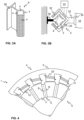
- Figures 7A and 7B illustrate schematically portions of magnetic core 2, 3 according to two embodiments of the present invention.
- Fig. 7A illustrates laminate-type elements 71, such as, of electrical steel laminates.
- the magnetic flux 50 is essentially confined within the laminate and, thus, amount of eddy currents is decreased with respect to the case where the core is made solid or "bulk" material.
- Fig. 7B illustrates filaments, or filament-type of elements or "bars", of magnetic core 2, 3 elements or parts having a square cross section 72. Filament elements or parts 72 having a square cross section further reduce eddy current losses with respect to laminate-type elements 71 having the same cross sectional area due to shorter possible path for the eddy currents.
- laminate-type 71 or filament elements or parts 72 having a square cross section or part 72 of magnetic core 2, 3, for example, may be fixed relative to each other, for example, by joint elements 73.
- the filaments elements 72 having a square cross section may be separated from each other, thus, further reducing amount of eddy currents, for instance.
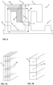
- Figure 8A illustrates a magnetic core, especially magnetic teeth 13, 15 thereof, for example, of an electric linear motor 1, manufactured by using laminates as a cross-sectional view according to an embodiment of the present invention.
- the air gap 17 in the Fig. 8A is shown to be between a magnetic tooth 13 of the mover 5 and a magnetic tooth 15 of the stator 4, the air gap 17 such as shown in Fig. 8A may as well reside in any magnetic circuit, for example, in an inductor core.
- magnetic flux 50 follows the shape of the laminate and therefore bends in the air gap 17.
- the shape of the ends of the magnetic teeth 13, 15 have rectangular shape due to using laminates.
- Figure 8B illustrates a magnetic core, especially magnetic teeth 13, 15 thereof, for example, of an electric linear motor 1, according to another embodiment of the present invention.
- the ends of the magnetic teeth have been shaped to focus the magnetic flux with respect to the air gap 17.
- the teeth 13, 15 may be manufactured of solid material, for example, by casting or, preferably, by additive manufacturing methods or 3D printing, such as, selective laser sintering (SLS) or, more preferably, selective laser melting (SLM).
- SLS selective laser sintering
- SLM selective laser melting
- each portion of the core may be shaped to follow the 3D shape best suited for the corresponding portion of the magnetic core.
- the magnetic flux 50 tends to bend less in the laminated structure relative to structure of solid material, as in Fig.
- flux 50 may be focused by the structure of the teeth 13, 15 shown in Fig. 8B .
- the teeth 13, 15 in Fig. 8B are made to narrow towards the air gap 17 in order to focus the flux 50 into the air gap 17, thus leading to a higher flux density in the airgap 17.
- the magnetic teeth 13, 15, one or several may be manufactured as having a laminated structure, such as, by utilizing additive manufacturing method or electrical steel laminates.
- the narrowing of the teeth 13, 15 with respect to the end of the teeth 13, 15 at the air gap 17 may be implemented by reducing the amount of laminates comprised in the teeth 13, 15 and, by this, making the teeth 13, 15 narrower at the end of the teeth 13, 15 at the air gap 17 with respect to the part of the teeth farther from said end of the teeth 13, 15.
- the laminates may be merged so that the magnetic flux 50 flowing, when the core is in use, in two or more laminates is directed or focused into one laminate or at least fewer number of laminates with respect to number of laminates farther away from the air gap 17 in order to make the teeth 13, 15 narrower for focusing the flux 50.
- the teeth 13, 15 may be manufactured to continuously narrow towards to end of the teeth 13, 15 at the air gap 17. This may also be implemented by manufacturing the teeth 13, 15 to have a laminated structure. The laminates may then be merged such that the teeth 13, 15 is continuous, meaning that there are no discontinuous points between the laminates in the direction of the longitudinal length of the teeth 13, 15. This allows the magnetic flux 50 to be effectively focused by narrowing the teeth 13, 15 towards the air gap 17.
- the magnetic core 1 may be utilized in an electric linear motor 1.
- tangential force provides the thrusting force of the linear motor 1 for moving mover 5 along the stator beam 8 and it is proportional to the product of normal and tangential components of the magnetic flux density.
- the maximum flux density in the air gap 17 is the same as the saturation flux density of the core material.
- the airgap flux density is close to the saturation flux density, in the core shown in 8B it is possible to achieve saturation with only a small increase of total reluctance of magnetic circuit.
- the total reluctance of magnetic circuit would increase much more compared to the core shown in Fig. 8B .
- the area of the airgap may be made about 10-20 percent smaller with respect to the magnetic core shown in Fig. 8A .
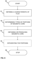
- Figure 9 illustrates a flow diagram of a method for manufacturing a magnetic core. Steps 90, 91, 92 and 99 are according to the invention. In step 93, the alternative “producing the magnetic core” is according to the invention. The alternative “obtaining magnetic core” is only an example not belonging to the invention. Since according to the invention, the at least two portions are integrated to each other during the producing, step 94 is only an example not belonging to the invention.
- the necessary tasks such as obtaining components and systems, and calibration and other configuration may take place. Specific care must be taken that the individual elements and material selections work together. Communication and electrical connections between various components and (sub-)systems may be established. At 90, specific materials may be obtained which may include different metals or metal alloys.
- defining at least one characteristic of magnetic flux for each of at least two portions of the magnetic core takes place. This may entail utilizing as the least one characteristic of magnetic flux a magnitude of magnetic flux in the corresponding portion of the magnetic core. For example, the magnitude of the magnetic flux in the portion of the magnetic core designed to be high, and, thus, certain ferromagnetic materials are better suited which have high magnetic saturation. Alternatively or in addition, the variation of the magnetic flux may be utilized as the characteristic. In some portions of the magnetic core, the flux may be designed to be essentially constant while in other portions in may vary considerably. This may related to the variation of the magnitude of the magnetic flux and/or the direction of the flux.
- Fig. 6 illustrates the matter.
- the magnetic flux remains essentially constant.
- the flux is changing from minimum to maximum via zero.
- the flux is changing from zero to maximum.
Landscapes
- Engineering & Computer Science (AREA)
- Power Engineering (AREA)
- Manufacturing & Machinery (AREA)
- Chemical & Material Sciences (AREA)
- Materials Engineering (AREA)
- Iron Core Of Rotating Electric Machines (AREA)
- Linear Motors (AREA)
Claims (12)
- Verfahren zur Herstellung eines Magnetkerns (2, 3) für eine elektrische Maschine, wobei das Verfahren umfasst:- Definieren (91) mindestens einer Charakteristik des magnetischen Flusses (50) für jeden von mindestens zwei Abschnitten (61-63) des Magnetkerns (2, 3), wobei die mindestens eine Charakteristik eine Eigenschaft des magnetischen Flusses (50) während einer beabsichtigten Verwendung des Magnetkerns (2, 3) repräsentiert,- Bestimmen (92) eines Typs von jedem der mindestens zwei Abschnitte (61-63) des Magnetkerns (2, 3) basierend auf der definierten mindestens einen Charakteristik, die den entsprechenden Abschnitt des Magnetkerns (2, 3) repräsentiert, wobei sich der Typ von einem der mindestens zwei Abschnitte (61-63) relativ zu dem Typ von einem anderen der mindestens zwei Abschnitte (61-63) unterscheidet, und wobei die bestimmten Typen mindestens zwei des Folgenden sind: Laminat, Filament, Feststoff, und- Produzieren (93) des Magnetkerns (2, 3) durch ein 3D-Druckverfahren als ein einteiliges Kernteil, das die mindestens zwei Abschnitte (61-63) umfasst, die die bestimmten Typen aufweisen und aufeinanderfolgend entlang eines Pfades des magnetischen Flusses (50) während der beabsichtigten Verwendung angeordnet sind, wobei die mindestens zwei Abschnitte (61-63) während des Produzierens (93) durch das 3D-Druckverfahren miteinander integriert werden.
- Verfahren nach Anspruch 1, wobei die mindestens eine Charakteristik des magnetischen Flusses eine Größe des magnetischen Flusses in dem entsprechenden Abschnitt des Magnetkerns (2, 3) ist.
- Verfahren nach Anspruch 1 oder 2, wobei die mindestens eine Charakteristik des magnetischen Flusses eine Variation der Größe des magnetischen Flusses in dem entsprechenden Abschnitt des Magnetkerns (2, 3) ist.
- Verfahren nach einem der vorstehenden Ansprüche, umfassend Anordnen der mindestens zwei Abschnitte (61-63) des Magnetkerns (2, 3) in Abhängigkeit von einer Richtung des magnetischen Flusses.
- Verfahren nach einem der vorstehenden Ansprüche, wobei die bestimmten Typen der mindestens zwei Abschnitte (61-63) des Magnetkerns (2, 3) ein Element (71) vom Laminattyp umfassen.
- Verfahren nach einem der vorstehenden Ansprüche, wobei die bestimmten Typen der mindestens zwei Abschnitte (61-63) des Magnetkerns (2, 3) einen Typ umfassen, der ein Filament-Element (72) mit im Wesentlichen einer quadratischen Querschnittsfläche ist.
- Verfahren nach einem der vorstehenden Ansprüche, wobei die bestimmten Typen der mindestens zwei Abschnitte (61-63) des Magnetkerns (2, 3) Feststofftyp umfassen.
- Verfahren nach einem der vorstehenden Ansprüche, wobei das 3D-Druckverfahren selektives Laserschmelzen oder -sintern ist.
- Verfahren nach einem der vorstehenden Ansprüche, wobei der Magnetkern (2, 3) einen Luftspalt (17) zwischen zwei Magnetzähnen (13, 15) umfasst, wobei das Verfahren derartiges Produzieren der Magnetzähne (13, 15) umfasst, dass Enden der Zähne (13, 15), die sich im Luftspalt (17) befinden, eine kleinere Querschnittsfläche relativ zu der Querschnittsfläche der Zähne (13, 15) an anderen Positionen aufweisen, um den magnetischen Fluss (50) in den Luftspalt (17) zu fokussieren.
- Magnetkern (2, 3) für eine elektrische Maschine, wobei der Magnetkern (2, 3) mindestens zwei Abschnitte (61-63) umfasst, wobei die mindestens zwei Abschnitte (61-63) unterschiedliche Typen von Abschnitte (61-63) in Abhängigkeit von einer Charakteristik des magnetischen Flusses (50) in dem entsprechenden Abschnitt sind, wobei die Charakteristik eine Eigenschaft des magnetischen Flusses (50) während einer beabsichtigten Verwendung des Magnetkerns (2, 3) repräsentiert, wobei einer der Abschnitte ein erster Abschnitt (61) ist, der eingerichtet ist zum Empfangen eines Permanentmagneten in Kontakt mit dem ersten Abschnitt, wobei der erste Abschnitt (61) aus einem ferromagnetischen Feststoffmaterial besteht, und ein Typ eines anderen der mindestens zwei Abschnitte (61-63) Laminat oder Filament ist, wobei die mindestens zwei Abschnitte (61-63) im Wesentlichen gleichzeitig durch ein 3D-Druckverfahren als ein einteiliges Kernteil des Kerns (61-63) produziert und miteinander integriert werden, wobei die mindestens zwei Abschnitte (61-63) aufeinanderfolgend entlang eines Pfades des magnetischen Flusses (50) während der beabsichtigten Verwendung angeordnet sind.
- Elektromotor, der einen Rotor (5) und einen Stator (4) umfasst, die in elektromagnetischem Eingriff miteinander angeordnet sind, wobei ein Magnetkern (2, 3) des Rotors (5) und/oder des Stators (4) durch ein Verfahren nach einem der Ansprüche 1-9 hergestellt wird und einen ersten Abschnitt (61) umfasst, wobei der Rotor (5) und/oder der Stator (4) einen Permanentmagneten in Kontakt mit dem ersten Abschnitt (61) umfassen.
- Aufzug (100), der mindestens eine Aufzugskabine (10) umfasst, die dazu ausgelegt ist, durch einen Elektromotor (1) bewegt zu werden, dadurch gekennzeichnet, dass der Elektromotor (1) ein Elektromotor (1) nach Anspruch 11 ist.
Priority Applications (4)
| Application Number | Priority Date | Filing Date | Title |
|---|---|---|---|
| EP17190378.4A EP3454455B1 (de) | 2017-09-11 | 2017-09-11 | Verfahren zur herstellung eines magnetkerns für eine elektrische maschine, elektrische maschine mit verwendung des magnetkerns daraus und magnetkern |
| PCT/EP2018/074261 WO2019048659A1 (en) | 2017-09-11 | 2018-09-10 | METHOD FOR MANUFACTURING A MAGNETIC CORE OF AN ELECTRIC MACHINE, ELECTRIC MACHINE USING THE MAGNETIC CORE, AND MAGNETIC CORE |
| CN201880058892.7A CN111095732B (zh) | 2017-09-11 | 2018-09-10 | 用于制造电机的磁芯的方法、利用其磁芯的电机以及磁芯 |
| US16/786,221 US11398345B2 (en) | 2017-09-11 | 2020-02-10 | Method for manufacturing a magnetic core of an electric machine |
Applications Claiming Priority (1)
| Application Number | Priority Date | Filing Date | Title |
|---|---|---|---|
| EP17190378.4A EP3454455B1 (de) | 2017-09-11 | 2017-09-11 | Verfahren zur herstellung eines magnetkerns für eine elektrische maschine, elektrische maschine mit verwendung des magnetkerns daraus und magnetkern |
Publications (3)
| Publication Number | Publication Date |
|---|---|
| EP3454455A1 EP3454455A1 (de) | 2019-03-13 |
| EP3454455B1 true EP3454455B1 (de) | 2025-06-25 |
| EP3454455C0 EP3454455C0 (de) | 2025-06-25 |
Family
ID=59858559
Family Applications (1)
| Application Number | Title | Priority Date | Filing Date |
|---|---|---|---|
| EP17190378.4A Active EP3454455B1 (de) | 2017-09-11 | 2017-09-11 | Verfahren zur herstellung eines magnetkerns für eine elektrische maschine, elektrische maschine mit verwendung des magnetkerns daraus und magnetkern |
Country Status (4)
| Country | Link |
|---|---|
| US (1) | US11398345B2 (de) |
| EP (1) | EP3454455B1 (de) |
| CN (1) | CN111095732B (de) |
| WO (1) | WO2019048659A1 (de) |
Families Citing this family (4)
| Publication number | Priority date | Publication date | Assignee | Title |
|---|---|---|---|---|
| GB2570927B (en) * | 2018-02-12 | 2023-05-31 | Epropelled Ltd | Electromagnetic devices |
| CN112260422A (zh) * | 2020-10-14 | 2021-01-22 | 中车株洲电机有限公司 | 一种电机及其轴向磁悬浮轴承定子 |
| JP2022127931A (ja) | 2021-02-22 | 2022-09-01 | 山洋電気株式会社 | モータの電機子構造及びその製造方法 |
| DE102022115198A1 (de) * | 2022-06-17 | 2023-12-28 | Ford Global Technologies, Llc | Verfahren zum Herstellen eines Rotorelements für einen Rotor einer elektrischen Maschine, Rotorelement, Rotor, elektrische Maschine und Kraftfahrzeug |
Citations (3)
| Publication number | Priority date | Publication date | Assignee | Title |
|---|---|---|---|---|
| EP2961040A1 (de) * | 2013-02-20 | 2015-12-30 | Mitsubishi Electric Corporation | Elektromotor mit eingebetteten permanentmagneten |
| US20170063183A1 (en) * | 2015-08-29 | 2017-03-02 | Abb Technology Ag | Electrical machines and fabrication methods therefor |
| US20170126087A1 (en) * | 2015-10-30 | 2017-05-04 | Rod F. Soderberg | Device including material originating from magnetic particles providing structural and magnetic capabilities |
Family Cites Families (22)
| Publication number | Priority date | Publication date | Assignee | Title |
|---|---|---|---|---|
| GB2149226B (en) * | 1983-09-05 | 1987-09-09 | Papst Motoren Gmbh & Co Kg | Collectorless d c motor |
| US5945902A (en) * | 1997-09-22 | 1999-08-31 | Zefv Lipkes | Core and coil structure and method of making the same |
| JP4003382B2 (ja) * | 2000-07-14 | 2007-11-07 | セイコーエプソン株式会社 | 発電機および電子制御式機械時計 |
| JP3865734B2 (ja) * | 2003-07-29 | 2007-01-10 | ファナック株式会社 | モータ、及びモータ製造装置 |
| US20080172861A1 (en) * | 2007-01-23 | 2008-07-24 | Holmes Alan G | Methods for manufacturing motor core parts with magnetic orientation |
| US7845065B2 (en) * | 2007-11-07 | 2010-12-07 | Gm Global Technology Operations, Inc. | Method of making a rotating electric machine stator core |
| JP5020034B2 (ja) * | 2007-11-22 | 2012-09-05 | 三菱電機株式会社 | 回転電機 |
| WO2010109272A2 (de) * | 2009-03-26 | 2010-09-30 | Vacuumschmelze Gmbh & Co. Kg | Blechpaket mit weichmagnetischem werkstoff und verfahren zum stoffschlüssigen fügen von paketlamellen zu einem weichmagnetischen blechpaket |
| US20130162064A1 (en) * | 2011-12-22 | 2013-06-27 | Samsung Electro-Mechanics Co., Ltd. | Laminated core and method for manufacturing the same |
| US10518490B2 (en) * | 2013-03-14 | 2019-12-31 | Board Of Regents, The University Of Texas System | Methods and systems for embedding filaments in 3D structures, structural components, and structural electronic, electromagnetic and electromechanical components/devices |
| JP5993580B2 (ja) * | 2012-02-14 | 2016-09-14 | 日本発條株式会社 | モーターのステーター・コア及び製造方法 |
| US9621013B2 (en) * | 2013-03-15 | 2017-04-11 | Ingersoll-Rand Company | Rotating machine with magnetic bearing |
| KR101677317B1 (ko) * | 2013-07-03 | 2016-11-17 | 주식회사 포스코 | 철손저감 및 강도향상을 위한 전기강판 적층코어의 제조방법 및 이에 의해 제조된 적층코어 |
| CN103904836B (zh) * | 2014-03-07 | 2016-08-17 | 江苏通达动力科技股份有限公司 | 一种直驱永磁发电机定子铁芯的叠压装置及其叠压方法 |
| EP3163717B1 (de) * | 2014-06-24 | 2024-04-03 | Kubota Corporation | Stator eines elektromotors und kühlstruktur für eine dynamoelektrische maschine |
| CN106796835B (zh) * | 2014-08-12 | 2019-05-21 | Abb瑞士股份有限公司 | 具有不同磁性质的区域的磁体以及用于形成这种磁体的方法 |
| EP2996119A1 (de) * | 2014-09-09 | 2016-03-16 | Premo, S.L. | Flexibler Magnetkern, Antenne mit flexiblem Magnetkern und Verfahren zur Herstellung eines flexiblen Magnetkerns |
| US9906111B2 (en) * | 2014-10-21 | 2018-02-27 | Xiuhong Sun | Fine element magnet array |
| JP6343556B2 (ja) * | 2014-12-09 | 2018-06-13 | 株式会社三井ハイテック | 積層鉄心用積層体及びその製造方法並びに積層鉄心の製造方法 |
| JP6343557B2 (ja) * | 2014-12-24 | 2018-06-13 | 株式会社三井ハイテック | 回転子用積層体及びその製造方法並びに回転子の製造方法 |
| US10483812B2 (en) * | 2014-12-31 | 2019-11-19 | Ingersoll-Rand Company | Electrical machine and method of manufacture |
| TWI576872B (zh) * | 2015-12-17 | 2017-04-01 | 財團法人工業技術研究院 | 磁性元件的製造方法 |
-
2017
- 2017-09-11 EP EP17190378.4A patent/EP3454455B1/de active Active
-
2018
- 2018-09-10 WO PCT/EP2018/074261 patent/WO2019048659A1/en not_active Ceased
- 2018-09-10 CN CN201880058892.7A patent/CN111095732B/zh active Active
-
2020
- 2020-02-10 US US16/786,221 patent/US11398345B2/en active Active
Patent Citations (3)
| Publication number | Priority date | Publication date | Assignee | Title |
|---|---|---|---|---|
| EP2961040A1 (de) * | 2013-02-20 | 2015-12-30 | Mitsubishi Electric Corporation | Elektromotor mit eingebetteten permanentmagneten |
| US20170063183A1 (en) * | 2015-08-29 | 2017-03-02 | Abb Technology Ag | Electrical machines and fabrication methods therefor |
| US20170126087A1 (en) * | 2015-10-30 | 2017-05-04 | Rod F. Soderberg | Device including material originating from magnetic particles providing structural and magnetic capabilities |
Also Published As
| Publication number | Publication date |
|---|---|
| WO2019048659A1 (en) | 2019-03-14 |
| CN111095732A (zh) | 2020-05-01 |
| EP3454455A1 (de) | 2019-03-13 |
| CN111095732B (zh) | 2023-05-23 |
| US20200176183A1 (en) | 2020-06-04 |
| US11398345B2 (en) | 2022-07-26 |
| EP3454455C0 (de) | 2025-06-25 |
Similar Documents
| Publication | Publication Date | Title |
|---|---|---|
| US20230054909A1 (en) | Torque tunnel halbach array electric machine | |
| US11398345B2 (en) | Method for manufacturing a magnetic core of an electric machine | |
| AU2008209912B2 (en) | Ring motor | |
| US20240380256A1 (en) | Segmented stator for a permanent magnet electric machine having a fractional-slot concentrated winding | |
| AU2011313817B2 (en) | Electromagnetic machine | |
| CN103329401B (zh) | 用于具有低损耗磁性材料的电动马达或发电机的定子及其制造方法 | |
| EP2159903A2 (de) | Transversalflussmaschine | |
| US10491061B2 (en) | Rotor for a reluctance machine | |
| US12095394B2 (en) | Induction machines without permanent magnets | |
| US8653713B2 (en) | Magnetic circuit structure | |
| CN106716781B (zh) | 具有低的槽漏磁的电机器 | |
| US7155804B2 (en) | Method of forming an electric motor | |
| US20200106351A1 (en) | Axial flux machine | |
| US20190214179A1 (en) | A core element for a magnetic component and a method for manufacturing the same | |
| US20150247530A1 (en) | Active part of an electrical machine, radial magnetic bearing and method for producing a radial magnetic bearing | |
| KR101048055B1 (ko) | 코어에 슬릿을 형성한 횡자속 전기기기 | |
| Noguchi et al. | Eddy-current loss analysis of copper-bar windings of ultra high-speed PM motor | |
| WO2002049190A1 (en) | Composite stator | |
| US20150022033A1 (en) | Method for manufacturing a rotor of a synchronous reluctance motor, a rotor of a synchronous reluctance motor, and a synchronous reluctance motor | |
| Shen et al. | Analysis and optimization of a modular stator core with segmental teeth and solid back iron for pm electric machines | |
| US20220069681A1 (en) | Method for winding a heavy gauge toroidal coil of an electric machine | |
| HK40019018B (en) | Method for manufacturing a magnetic core of an electric machine, an electric machine utilizing the magnetic core thereof, and a magnetic core | |
| HK40019018A (en) | Method for manufacturing a magnetic core of an electric machine, an electric machine utilizing the magnetic core thereof, and a magnetic core | |
| Liu et al. | Influence of the stator deformation on the behaviour of a claw-pole generator | |
| JP4470249B2 (ja) | 電動機およびその固定子鉄心の製造方法 |
Legal Events
| Date | Code | Title | Description |
|---|---|---|---|
| PUAI | Public reference made under article 153(3) epc to a published international application that has entered the european phase |
Free format text: ORIGINAL CODE: 0009012 |
|
| STAA | Information on the status of an ep patent application or granted ep patent |
Free format text: STATUS: THE APPLICATION HAS BEEN PUBLISHED |
|
| AK | Designated contracting states |
Kind code of ref document: A1 Designated state(s): AL AT BE BG CH CY CZ DE DK EE ES FI FR GB GR HR HU IE IS IT LI LT LU LV MC MK MT NL NO PL PT RO RS SE SI SK SM TR |
|
| AX | Request for extension of the european patent |
Extension state: BA ME |
|
| STAA | Information on the status of an ep patent application or granted ep patent |
Free format text: STATUS: REQUEST FOR EXAMINATION WAS MADE |
|
| 17P | Request for examination filed |
Effective date: 20190913 |
|
| RBV | Designated contracting states (corrected) |
Designated state(s): AL AT BE BG CH CY CZ DE DK EE ES FI FR GB GR HR HU IE IS IT LI LT LU LV MC MK MT NL NO PL PT RO RS SE SI SK SM TR |
|
| STAA | Information on the status of an ep patent application or granted ep patent |
Free format text: STATUS: EXAMINATION IS IN PROGRESS |
|
| 17Q | First examination report despatched |
Effective date: 20200204 |
|
| P01 | Opt-out of the competence of the unified patent court (upc) registered |
Effective date: 20230525 |
|
| GRAP | Despatch of communication of intention to grant a patent |
Free format text: ORIGINAL CODE: EPIDOSNIGR1 |
|
| STAA | Information on the status of an ep patent application or granted ep patent |
Free format text: STATUS: GRANT OF PATENT IS INTENDED |
|
| RIC1 | Information provided on ipc code assigned before grant |
Ipc: H02K 1/02 20060101ALN20250225BHEP Ipc: H02K 41/03 20060101ALN20250225BHEP Ipc: H01F 41/02 20060101ALI20250225BHEP Ipc: B33Y 80/00 20150101ALI20250225BHEP Ipc: H02K 15/022 20250101ALI20250225BHEP Ipc: H02K 1/14 20060101AFI20250225BHEP |
|
| INTG | Intention to grant announced |
Effective date: 20250306 |
|
| GRAS | Grant fee paid |
Free format text: ORIGINAL CODE: EPIDOSNIGR3 |
|
| GRAA | (expected) grant |
Free format text: ORIGINAL CODE: 0009210 |
|
| STAA | Information on the status of an ep patent application or granted ep patent |
Free format text: STATUS: THE PATENT HAS BEEN GRANTED |
|
| AK | Designated contracting states |
Kind code of ref document: B1 Designated state(s): AL AT BE BG CH CY CZ DE DK EE ES FI FR GB GR HR HU IE IS IT LI LT LU LV MC MK MT NL NO PL PT RO RS SE SI SK SM TR |
|
| REG | Reference to a national code |
Ref country code: GB Ref legal event code: FG4D |
|
| REG | Reference to a national code |
Ref country code: CH Ref legal event code: EP |
|
| REG | Reference to a national code |
Ref country code: DE Ref legal event code: R096 Ref document number: 602017090106 Country of ref document: DE |
|
| REG | Reference to a national code |
Ref country code: CH Ref legal event code: EP |
|
| REG | Reference to a national code |
Ref country code: IE Ref legal event code: FG4D |
|
| U01 | Request for unitary effect filed |
Effective date: 20250701 |
|
| U07 | Unitary effect registered |
Designated state(s): AT BE BG DE DK EE FI FR IT LT LU LV MT NL PT RO SE SI Effective date: 20250707 |
|
| PG25 | Lapsed in a contracting state [announced via postgrant information from national office to epo] |
Ref country code: GR Free format text: LAPSE BECAUSE OF FAILURE TO SUBMIT A TRANSLATION OF THE DESCRIPTION OR TO PAY THE FEE WITHIN THE PRESCRIBED TIME-LIMIT Effective date: 20250926 Ref country code: NO Free format text: LAPSE BECAUSE OF FAILURE TO SUBMIT A TRANSLATION OF THE DESCRIPTION OR TO PAY THE FEE WITHIN THE PRESCRIBED TIME-LIMIT Effective date: 20250925 |
|
| PG25 | Lapsed in a contracting state [announced via postgrant information from national office to epo] |
Ref country code: HR Free format text: LAPSE BECAUSE OF FAILURE TO SUBMIT A TRANSLATION OF THE DESCRIPTION OR TO PAY THE FEE WITHIN THE PRESCRIBED TIME-LIMIT Effective date: 20250625 |
|
| PG25 | Lapsed in a contracting state [announced via postgrant information from national office to epo] |
Ref country code: RS Free format text: LAPSE BECAUSE OF FAILURE TO SUBMIT A TRANSLATION OF THE DESCRIPTION OR TO PAY THE FEE WITHIN THE PRESCRIBED TIME-LIMIT Effective date: 20250925 |
|
| U20 | Renewal fee for the european patent with unitary effect paid |
Year of fee payment: 9 Effective date: 20250924 |
|
| PG25 | Lapsed in a contracting state [announced via postgrant information from national office to epo] |
Ref country code: IS Free format text: LAPSE BECAUSE OF FAILURE TO SUBMIT A TRANSLATION OF THE DESCRIPTION OR TO PAY THE FEE WITHIN THE PRESCRIBED TIME-LIMIT Effective date: 20251025 |
|
| PG25 | Lapsed in a contracting state [announced via postgrant information from national office to epo] |
Ref country code: SM Free format text: LAPSE BECAUSE OF FAILURE TO SUBMIT A TRANSLATION OF THE DESCRIPTION OR TO PAY THE FEE WITHIN THE PRESCRIBED TIME-LIMIT Effective date: 20250625 |
|
| PG25 | Lapsed in a contracting state [announced via postgrant information from national office to epo] |
Ref country code: CZ Free format text: LAPSE BECAUSE OF FAILURE TO SUBMIT A TRANSLATION OF THE DESCRIPTION OR TO PAY THE FEE WITHIN THE PRESCRIBED TIME-LIMIT Effective date: 20250625 |
|
| PG25 | Lapsed in a contracting state [announced via postgrant information from national office to epo] |
Ref country code: PL Free format text: LAPSE BECAUSE OF FAILURE TO SUBMIT A TRANSLATION OF THE DESCRIPTION OR TO PAY THE FEE WITHIN THE PRESCRIBED TIME-LIMIT Effective date: 20250625 |
|
| PG25 | Lapsed in a contracting state [announced via postgrant information from national office to epo] |
Ref country code: SK Free format text: LAPSE BECAUSE OF FAILURE TO SUBMIT A TRANSLATION OF THE DESCRIPTION OR TO PAY THE FEE WITHIN THE PRESCRIBED TIME-LIMIT Effective date: 20250625 |
|
| PG25 | Lapsed in a contracting state [announced via postgrant information from national office to epo] |
Ref country code: ES Free format text: LAPSE BECAUSE OF FAILURE TO SUBMIT A TRANSLATION OF THE DESCRIPTION OR TO PAY THE FEE WITHIN THE PRESCRIBED TIME-LIMIT Effective date: 20250625 |
|
| PLBE | No opposition filed within time limit |
Free format text: ORIGINAL CODE: 0009261 |
|
| STAA | Information on the status of an ep patent application or granted ep patent |
Free format text: STATUS: NO OPPOSITION FILED WITHIN TIME LIMIT |