EP3454542B1 - Module de caméra et dispositif électronique - Google Patents
Module de caméra et dispositif électronique Download PDFInfo
- Publication number
- EP3454542B1 EP3454542B1 EP18192412.7A EP18192412A EP3454542B1 EP 3454542 B1 EP3454542 B1 EP 3454542B1 EP 18192412 A EP18192412 A EP 18192412A EP 3454542 B1 EP3454542 B1 EP 3454542B1
- Authority
- EP
- European Patent Office
- Prior art keywords
- sub
- movable member
- fixed member
- side wall
- camera module
- Prior art date
- Legal status (The legal status is an assumption and is not a legal conclusion. Google has not performed a legal analysis and makes no representation as to the accuracy of the status listed.)
- Active
Links
Images


Classifications
-
- H—ELECTRICITY
- H04—ELECTRIC COMMUNICATION TECHNIQUE
- H04M—TELEPHONIC COMMUNICATION
- H04M1/00—Substation equipment, e.g. for use by subscribers
- H04M1/02—Constructional features of telephone sets
- H04M1/0202—Portable telephone sets, e.g. cordless phones, mobile phones or bar type handsets
- H04M1/026—Details of the structure or mounting of specific components
- H04M1/0264—Details of the structure or mounting of specific components for a camera module assembly
-
- G—PHYSICS
- G02—OPTICS
- G02B—OPTICAL ELEMENTS, SYSTEMS OR APPARATUS
- G02B7/00—Mountings, adjusting means, or light-tight connections, for optical elements
- G02B7/02—Mountings, adjusting means, or light-tight connections, for optical elements for lenses
- G02B7/04—Mountings, adjusting means, or light-tight connections, for optical elements for lenses with mechanism for focusing or varying magnification
- G02B7/10—Mountings, adjusting means, or light-tight connections, for optical elements for lenses with mechanism for focusing or varying magnification by relative axial movement of several lenses, e.g. of varifocal objective lens
- G02B7/102—Mountings, adjusting means, or light-tight connections, for optical elements for lenses with mechanism for focusing or varying magnification by relative axial movement of several lenses, e.g. of varifocal objective lens controlled by a microcomputer
-
- H—ELECTRICITY
- H04—ELECTRIC COMMUNICATION TECHNIQUE
- H04N—PICTORIAL COMMUNICATION, e.g. TELEVISION
- H04N23/00—Cameras or camera modules comprising electronic image sensors; Control thereof
- H04N23/50—Constructional details
- H04N23/51—Housings
-
- H—ELECTRICITY
- H04—ELECTRIC COMMUNICATION TECHNIQUE
- H04N—PICTORIAL COMMUNICATION, e.g. TELEVISION
- H04N23/00—Cameras or camera modules comprising electronic image sensors; Control thereof
- H04N23/50—Constructional details
- H04N23/54—Mounting of pick-up tubes, electronic image sensors, deviation or focusing coils
-
- H—ELECTRICITY
- H04—ELECTRIC COMMUNICATION TECHNIQUE
- H04N—PICTORIAL COMMUNICATION, e.g. TELEVISION
- H04N23/00—Cameras or camera modules comprising electronic image sensors; Control thereof
- H04N23/50—Constructional details
- H04N23/55—Optical parts specially adapted for electronic image sensors; Mounting thereof
-
- H—ELECTRICITY
- H04—ELECTRIC COMMUNICATION TECHNIQUE
- H04N—PICTORIAL COMMUNICATION, e.g. TELEVISION
- H04N23/00—Cameras or camera modules comprising electronic image sensors; Control thereof
- H04N23/57—Mechanical or electrical details of cameras or camera modules specially adapted for being embedded in other devices
Definitions
- the present disclosure relates to a technical field of consumer electronics, and particularly to a camera module and an electronic device.
- US2017/0192199A1 discloses an attachable lens module, which includes: a housing including an internal space; a fixed lens group mounted in the internal space and including a lens aligned on an optical axis of the lens module; and a moving lens group comprising a moving lens, and configured to move along a guide rail mounted in the housing to be aligned with the fixed lens group on the optical axis.
- US2012/0020654A1 discloses a photographic optical device, which may include a movable module having a camera module on which a lens and an imaging element are mounted, a support body, and a shake correction mechanism.
- the movable module may be provided with a sensor for detecting an inclination of the camera module and a cover member which structures an outer peripheral face of the movable module.
- the shake correction mechanism may be provided with a swing drive mechanism for swinging the movable module so that the optical axis is inclined.
- the swing drive mechanism may be provided with a drive magnet and a drive coil.
- WO2017080432A1 discloses a camera device that includes a light filter switching device and a camera module.
- the camera module includes a photosensitive assembly and a lens assembly arranged on a photosensitive path of the photosensitive assembly.
- the light filter switching device is used for selectively filtering out infrared rays or enabling the infrared rays to pass through.
- Embodiments of the present disclosure provide a camera module and an electronic device.
- the camera module includes a fixed member, a movable member, a lens unit, and a driving member.
- the fixed member has a top surface, the a top surface of the fixed member is provided with a through hole, the top surface is a step surface and includes a first sub-top-surface and a second sub-top-surface connected with each other, the first sub-top-surface is inclined with respect to the second sub-top-surface and defines a notch together with the second sub-top-surface.
- the movable member is accommodated in the fixed member.
- the lens unit is accommodated in the movable member.
- the movable member corresponds to the through hole
- the lens unit corresponds to the through hole
- the driving member is provided in the fixed member and located at a side of the fixed member away from the notch, and the driving member is configured to drive the movable member to lead the lens unit to move along an optical axis of the lens unit.
- the notch communicates with the through hole, a gap corresponding to the notch being provided in a position of the movable member corresponding to the notch, and the gap and the first sub-top-surface are parallel with each other and located in the same plane.
- the first sub-top-surface is a flat surface
- the second sub-top-surface is a flat surface or a curved surface.
- the top surface further includes a third sub-top-surface connected with the second sub-top-surface, the third sub-top-surface and the first sub-top-surface are located at two opposite sides of the second sub-top-surface correspondingly, the third sub-top-surface is inclined relative to the second sub-top-surface and defines the notch together with the second sub-top-surface and the first sub-top-surface.
- the first sub-top-surface is a flat surface
- the third sub-top-surface is a flat surface or a curved surface
- the third sub-top-surface is parallel with the first sub-top-surface
- the fixed member includes a body and a side plate, a side of the body of the fixed member away from the notch is provided with an accommodating groove, the side plate is detachably accommodated in the accommodating groove so that an accommodating space for accommodating the movable member, the lens assembly and the driving member is enclosed by the side plate together with the body of the fixed member.
- the fixed member further includes a guide rail provided to the side plate, the guide rail of the fixed member is arranged along a direction of the optical axis, the movable member is provided with a guide slot fitted with the guide rail of the fixed member, the driving member is able to drive the movable member to slide along the guide rail of the fixed member.
- the movable member includes a body and a guide rail provided to the body of the movable member, the guide rail of the movable member is arranged along a direction of the optical axis, the fixed member is provided with a guide slot fitted with the guide rail of the movable member, the driving member is able to drive the movable member to slide along the guide slot of the fixed member.
- the guide slot of the fixed member is provided in any one of side walls of the body of the fixed member; or the guide slot of the fixed member is provided in the side plate.
- the fixed member further includes a ball assembly provided to the side plate, the ball assembly of the fixed member is arranged along a direction of the optical axis, the movable member is provided with a ball guide groove fitted with the ball assembly of the fixed member, the driving member is able to drive the movable member to slide along the ball assembly of the fixed member.
- the side plate is provided with a ball guide groove
- the ball guide groove of the side plate is arranged along a direction of the optical axis
- the movable member further includes a ball assembly provided to the movable member and fitted with the ball guide groove of the side plate
- the driving member is able to drive the movable member to slide along the ball guide groove of the side plate.
- the driving member includes a driving coil and a driving magnet corresponding to the driving coil, the driving coil is arranged at the side plate and accommodated in the accommodating space, and the driving magnet is arranged at a side of the movable member away from the notch and opposite to the driving coil.
- the driving member further includes a feedback magnet, a hall element corresponding to the feedback magnet, and a processing chip connected with the hall element, the hall element is arranged at the side plate and accommodated in the accommodating space, the feedback magnet is arranged at a side of the movable member away from the notch and opposite to the hall element, the processing chip is able to control the driving member to drive the movable member to move according to a position of the feedback magnet detected by the hall element.
- the fixed member exhibits a barrel shape having a rectangular section contour
- the fixed member includes a first side wall, a second side wall, a third side wall, a fourth side wall, and a bottom wall; the first side wall is opposite to the third side wall, the second side wall is opposite to the fourth side wall, and the bottom wall is connected to each of the first side wall, the second side wall, the third side wall and the fourth side wall; an accommodating space for accommodating the movable member, the lens unit and the driving member is enclosed by the first side wall, the second side wall, the third side wall, the fourth side wall and the bottom wall together; and the top surface is opposite to the bottom wall.
- the electronic device includes a casing provided with a mounting hole; a camera module according to any one of the above-mentioned embodiments, the camera module being mounted in the mounting hole; and a display module, the display module being mounted in the casing, covering the notch and exposing the lens unit.
- the side of the fixed member away from the driving member is provided with the notch, so that a volume of the camera module can be reduced and a display screen is able to be arranged at the notch to be more adjacent to the camera module, thereby increasing the screen-to-body ratio of the screen assembly; meanwhile, the driving member can drive the movable member to lead the lens assembly to move along the optical axis, so that the camera module has a zoom function.
- first and second are used herein for purposes of description and are not intended to indicate or imply relative importance or significance or to imply the number of indicated technical features.
- the feature defined with “first” and “second” may comprise one or more of this feature.
- a plurality of' means two or more than two, unless specified otherwise.
- the terms “mounted,” “connected,” “coupled” and the like are used broadly, and may be, for example, fixed connections, detachable connections, or integral connections; may also be mechanical or electrical connections or communicable with each other; may also be direct connections or indirect connections via intervening structures; may also be inner communications or interaction relationship of two elements, which can be understood by those skilled in the art according to specific situations.
- a structure in which a first feature is "on" or “below” a second feature may include an embodiment in which the first feature is in direct contact with the second feature, and may also include an embodiment in which the first feature and the second feature are not in direct contact with each other, but are contacted via an additional feature formed therebetween.
- a first feature "on,” “above,” or “on top of' a second feature may include an embodiment in which the first feature is right or obliquely “on,” “above,” or “on top of' the second feature, or just means that the first feature is at a height higher than that of the second feature; while a first feature "below,” “under,” or “on bottom of' a second feature may include an embodiment in which the first feature is right or obliquely “below,” “under,” or “on bottom of' the second feature, or just means that the first feature is at a height lower than that of the second feature.
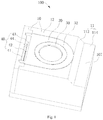
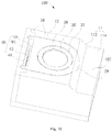
- a camera module 100 of embodiments of the present disclosure includes a fixed member 10, a movable member 20, a lens unit 30 and a driving member 40.
- a top surface 11 of the fixed member 10 is provided with a through hole 12, the top surface 11 is a step surface and includes a first sub-top-surface 112 and a second sub-top-surface 114 connected with each other.
- the first sub-top-surface 112 is inclined relative to the second sub-top-surface 114 and defines a notch 107 together with the second sub-top-surface 114.
- the movable member 20 is accommodated in the fixed member 10 and corresponds to the through hole 12.
- the lens unit 30 is accommodated in the movable member 20 and corresponds to the through hole 12.
- the driving member 40 is provided in the fixed member 10 and located at a side of the fixed member 10 away from the notch 107, the driving member 40 is configured to drive the movable member 20 to lead the lens unit 30 to move along an optical axis of the lens unit 30.
- the first sub-top-surface 112 can be a flat surface
- the second sub-top-surface 114 can be a flat surface or a curved surface
- the shapes of the first sub-top-surface 112 and the second sub-top-surface 114 can fall within the protective scope of the present disclosure as along as the notch 107 formed by the first sub-top-surface 112 and the second sub-top-surface 114 can reduce the volume of the fixed member 10.
- the notch 107 can be communicated with the through hole 12, or the notch 107 is not communicated with the through hole 12 and is located at a side of the through hole 12.
- the side of the fixed member 10 away from the driving member 40 is provided with the notch 107, so that a volume of the camera module 100 can be reduced and a display screen is able to be arranged at the notch to be more adjacent to the camera module 100, thereby increasing the screen-to-body ratio of the screen assembly; meanwhile, the driving member 40 can drive the movable member 20 to lead the lens unit 30 to move along the optical axis, so that the camera module 100 has a zoom function.
- the camera module 100 of embodiments of the present disclosure includes the fixed member 10, the movable member 20, the lens unit 30 and the driving member 40.
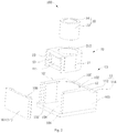
- the fixed member 10 can exhibit a barrel shape having a rectangular section contour.
- the fixed member 10 includes a first side wall 101, a second side wall 102, a third side wall 103, a fourth side wall 104, and a bottom wall 106.
- the first side wall 101 is opposite to the third side wall 103
- the second side wall 102 is opposite to the fourth side wall 104
- the bottom wall 106 is connected to each of the first side wall 101, the second side wall 102, the third side wall 103 and the fourth side wall 104.
- An accommodating space 108 is enclosed by the first side wall 101, the second side wall 102, the third side wall 103, the fourth side wall 104 and the bottom wall 106 together.
- the fixed member 10 includes a top surface 11 opposite to the bottom wall 106, the top surface 11 is provided with the through hole 12 communicated with the accommodating space 108.
- the top surface 11 is the step surface and includes the first sub-top-surface 112 and the second sub-top-surface 114 connected with each other.
- the first sub-top-surface 112 is inclined relative to the second sub-top-surface 114 and defines the notch 107 together with the second sub-top-surface 114.
- the notch 107 runs through the first side wall 101 and the third side wall 103 and is provided at an end of the second side wall 102 adjacent to the top surface 11.
- the accommodating space 108 may have a circular, triangular, rectangular or polygonal section.
- the fixed member 10 can also exhibit a barrel structure having a circular, triangular, or polygonal section contour.
- the bottom wall 106 can be detachably connected with the first side wall 101, the second side wall 102, the third side wall 103 and the fourth side wall 104.
- the fixed member 10 is provided with a guide slot 109, the guide slot 109 of the fixed member 10 is arranged along a direction of the optical axis of the camera module 100, that is, a longitudinal direction of the guide slot 109 of the fixed member 10 is substantially parallel to the optical axis of the camera module 100.
- One or a plurality of guide slots 109 of the fixed member 10 may be provided.
- the one guide slot 109 of the fixed member 10 may be arranged in any one of the first side wall 101, the third side wall 103 and the fourth side wall 104; when the plurality of guide slots 109 of the fixed member 10 is provided, the plurality of guide slots 109 of the fixed member 10 may be arranged in any one or more of the first side wall 101, the third side wall 103 and the fourth side wall 104.
- the guide slot 109 of the fixed member 10 is arranged in the first side wall 101 or the third side wall 103, the guide slot 109 of the fixed member 10 and the notch 107 are staggered.
- the guide slot 109 of the fixed member 10 is arranged in the fourth side wall 104.
- the movable member 20 includes a body 21 and a guide rail 22 provided to the body 21.
- the number of the guide rail 22 of the movable member 20 is the same as the number of the guide slot 109 of the fixed member 10.
- a position of the guide rail 22 of the movable member 20 corresponds to a position of the guide slot 109 of the fixed member 10.
- the guide rail 22 of the movable member 20 is fitted in the guide slot 109 of the fixed member 10 and is able to slide along the guide slot 109 of the fixed member 10.
- the movable member 20 can be movably accommodated in the accommodating space 108.
- a shape of the movable member 20 matches a shape of the accommodating space 108.
- the body 21 of the movable member 20 is provided with an accommodating hole 212.
- the lens unit 30 includes a lens barrel 32 and an optical lens 34 provided in the lens barrel 32.
- the lens barrel 32 is accommodated and fixed in the accommodating hole 212.
- the lens unit 30 can move along with a movement of the movable member 20.
- the lens barrel 32 may be integrally formed with the movable member 20.
- the driving member 40 includes a driving coil 41 and a driving magnet 42 corresponding to the driving coil 41.
- the driving coil 41 is arranged at the fourth side wall 104 and accommodated in the accommodating space 108.
- the driving magnet 42 is arranged at a side of the movable member 20 away from the notch 107 and opposite to the driving coil 41.
- the driving coil 41 When the driving coil 41 is energized, the driving coil 41 drives the driving magnet 42 to lead the movable member 20 and the lens unit 30 provided in the movable member 20 to slide along the guide slot 109 of the fixed member 10.
- the electronic device 200 of the embodiment of the present disclosure includes a casing 70, a camera module 100 and a display module 80.
- the electronic device 200 includes but is not limited to a mobile phone, a tablet computer, a smart watch. This embodiment is illustrated with the mobile phone being taken as an example of the electronic device 200.
- the casing 70 is provided with a mounting hole 72.
- the camera module 100 is mounted in the mounting hole 72.
- the display module 80 is mounted in a central position of the casing 70, covers the notch 107 of the camera module 100 and exposes the lens unit 30. Specifically, in a light emitting direction of the display module 80, the display module 80 can cover a part of the first sub-top-surface 112, and the display module 80 can also cover a part of the second sub-top-surface 114.
- the side of the fixed member 10 away from the driving member 40 is provided with the notch 107, so that the volume of the camera module 100 can be reduced.
- the driving member 40 can drive the movable member 20 to lead the lens unit 30 to move along the optical axis, so that the camera module 100 has the zoom function.
- the electronic device 200 of the embodiment of the present disclosure further has the following beneficial effects: the display module 80 is arranged at the notch 107 and exposes the lens unit 30, thereby reducing the space of the casing 70 occupied by the camera module 100, increasing the screen-to-body ratio of the display module 80.
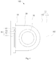
- the top surface 11 in the above-mentioned embodiments further includes a third sub-top-surface 116 connected with the second sub-top-surface 114, the third sub-top-surface 116 and the first sub-top-surface 112 are located at two opposite sides of the second sub-top-surface 114 correspondingly.
- the third sub-top-surface 116 is inclined relative to the second sub-top-surface 114 and defines the notch 107 together with the second sub-top-surface 114 and the first sub-top-surface 112.
- the third sub-top-surface 116 can be a flat surface or a curved surface.
- the third sub-top-surface 116 When the third sub-top-surface 116 is a flat surface, the third sub-top-surface 116 can be parallel with the first sub-top-surface 112. In the light emitting direction of the display module 80, the display module 80 can cover a part of the third sub-top-surface 116, or the display module 80 can completely cover the third sub-top-surface 116.
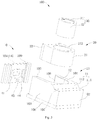
- the fixed member 10 of the above embodiments can be a split structure, and the fixed member 10 includes a body 13 and a side plate 14.
- the first side wall 101, the second side wall 102, the third side wall 103 and the bottom wall 106 together constitute the body 13 of the fixed member 10.
- the side plate 14 is the fourth side wall 104.
- the notch 107 runs through the first side wall 101 and the third side wall 103 and is arranged at the end of the second side wall 102 adjacent to the top surface 11.
- a side of the body 13 of the fixed member 10 away from the notch 107 is provided with an accommodating groove 132, and the side plate 14 is detachably accommodated in the accommodating groove 132 so that the accommodating space 108 for accommodating the movable member 20, the lens unit 30 and the driving member 40 is enclosed by the side plate 14 together with the body 13 of the fixed member 10.
- the guide slot 109 of the fixed member 10 can be arranged in the side plate 14 and located at a side of the accommodating space 108, and the guide rail 22 of the movable member 20 is arranged at a side corresponding to the side plate 14.
- the fixed member 10 includes the body 13 and the side plate 14, which facilitates the arrangements of the guide slot 109 of the fixed member 10 and the driving coil 41 in the side plate 14, and facilitates the installation of the movable member 20.
- the fixed member 10 of the above-mentioned embodiments further includes a guide rail 142 provided to the side plate 14, the guide rail 142 of the fixed member 10 is arranged along the direction of the optical axis, that is, a longitudinal direction of the guide slot 142 of the fixed member 10 is substantially parallel to the optical axis of the camera module 100, the movable member 20 is provided with a guide slot 24 fitted with the guide rail 142 of the fixed member 10, the driving member 40 is able to drive the movable member 20 to slide along the guide rail 142 of the fixed member 10.
- the fixed member 10 may not be provided with the guide slot 109, and the movable member 20 may not be provided with the guide rail 22.
- the fixed member 10 includes the body 13 and the side plate 14, which facilitates the arrangements of the guide rail 142 of the fixed member 10 and the driving coil 41 in the side plate 14, and facilitates the installation of the movable member 20.
- the fixed member 10 in the above-mentioned embodiments further includes a ball assembly 144 provided to the side plate 14, the ball assembly 144 of the fixed member 10 is arranged along a direction of the optical axis, that is, a longitudinal direction of the ball assembly 144 of the fixed member 10 is substantially parallel to the optical axis of the camera module 100, the movable member 20 is provided with a ball guide groove 26 fitted with the ball assembly 144 of the fixed member 10, the driving member 40 is able to drive the movable member 20 to slide along the ball assembly 144 of the fixed member 10.
- the ball assembly 144 of the fixed member 10 includes a ball holder and balls that are rotatably arranged in the ball holder.
- the ball assembly 144 of the fixed member 10 is fixed to the side plate 14 through the ball holder.
- the fixed member 10 includes the body 13 and the side plate 14, which facilitates the arrangements of the ball assembly 144 of the fixed member 10 and the driving coil 41 in the side plate 14, and facilitates the installation of the movable member 20. Meanwhile, since friction generated by the ball assembly 144 of the fixed member 10 rolling in the ball guide groove 26 of the movable member 20 is less relative to friction generated by the guide rail sliding in the guide groove, the sliding of the movable member 20 relative to the fixed member 10 is thus facilitated.
- the side plate 14 of the above-mentioned embodiments is provided with a ball guide groove 146
- the ball guide groove 146 of the side plate 14 is arranged along the direction of the optical axis, that is, a longitudinal direction of the guide groove 146 of the side plate 14 is substantially parallel to the optical axis of the camera module 100
- the movable member 20 further includes a ball assembly 28 provided to the movable member 20 and fitted with the ball guide groove 146 of the side plate 14, the driving member 40 is able to drive the movable member 20 to slide along the ball guide groove 146 of the side plate 14.
- the fixed member 10 includes the body 13 and the side plate 14, which facilitates the arrangements of the ball guide groove 146 of the side plate 14 and the driving coil 41 in the side plate 14, and facilitates the installation of the movable member 20. Meanwhile, since friction generated by the ball assembly 28 of the movable member 20 rolling in the ball guide groove 146 of the side plate 14 is less relative to friction generated by the guide rail sliding in the guide groove, the sliding of the movable member 20 relative to the fixed member 10 is thus facilitated.
- the driving member 40 of the above-mentioned embodiments further includes a feedback magnet 43, a hall element 44 corresponding to the feedback magnet 43, and a processing chip 45 connected with the hall element 44.
- the hall element 44 is arranged at the side plate 14 and accommodated in the accommodating space 108
- the feedback magnet 43 is arranged at a side of the movable member 20 away from the notch 107 and opposite to the hall element 44
- the processing chip 45 is able to control the driving member 40 to drive the movable member 20 to move according to a position of the feedback magnet 43 detected by the hall element 44.
- the processing chip 45 is further connected with the driving coil 41.
- the hall element 44 can determine a relative position between the feedback magnet 43 and the hall element 44 and determine a displacement of the movable member 20 based on the detected signal.
- the processing chip 45 controls the driving coil 41 to be energized according to the displacement.
- the driving coil 41 drives the driving magnet 42 to lead the movable member 20 and the lens unit 30 provided in the movable member 20 to slide so as to move the lens unit 30 to an appropriate position.
- the notch 107 of the above-mentioned embodiments is communicated with the through hole 12, a gap 29 corresponding to the notch 27 is provided in a position of the movable member 20 corresponding to the notch 107.
- the gap 29 and the first top surface 112 are parallel with each other and located in the same plane.
- the arrangement of the display module 80 on the notch 107 is not interfered by the movable member 20, thus the space of the casing 70 occupied by the camera module 100 is reduced and the screen-to-body ratio of the display module 80 is increased.
- first and second are used herein for purposes of description and are not intended to indicate or imply relative importance or significance or to imply the number of indicated technical features.
- the feature defined with “first” and “second” may comprise one or more of this feature.
- a plurality of means two or more than two, unless specified otherwise.
Landscapes
- Engineering & Computer Science (AREA)
- Signal Processing (AREA)
- Multimedia (AREA)
- Physics & Mathematics (AREA)
- General Physics & Mathematics (AREA)
- Optics & Photonics (AREA)
- General Engineering & Computer Science (AREA)
- Lens Barrels (AREA)
- Studio Devices (AREA)
Claims (14)
- Module appareil photo (100), comprenant :un élément fixe (10) ayant une surface supérieure (11), cette surface supérieure (11) étant pourvue d'un trou débouchant (12), cette surface supérieure (11) étant une surface à gradin et comprenant une première surface supérieure secondaire (112) et une deuxième surface supérieure secondaire (114) reliées l'une à l'autre, la première surface supérieure secondaire (112) étant inclinée par rapport à la deuxième surface supérieure secondaire (114) et définissant une encoche (107) avec la deuxième surface supérieure secondaire (114) ;un élément mobile (20) logé dans l'élément fixe (10) ;une unité objectif (30) logée dans l'élément mobile (20) ; etun élément d'entraînement (40),caractérisé en ce que :l'élément mobile (20) correspond au trou débouchant (12) ;l'unité objectif (30) correspond au trou débouchant (12) ; etl'élément d'entraînement (40) est prévu dans l'élément fixe (10) et situé sur un côté de l'élément fixe (10) éloigné de l'encoche (107),l'élément d'entraînement (40) étant configuré de façon à entraîner l'élément mobile (20) afin de mener l'unité objectif (30) pour qu'elle se déplace le long d'un axe optique de l'unité objectif (30),l'encoche (107) communiquant avec le trou débouchant (12), un espace (29) correspondant à l'encoche (107) étant prévu dans une position de l'élément mobile (20) correspondant à l'encoche (107), etl'espace (29) et la première surface supérieure secondaire (112) étant parallèles l'un à l'autre et situés dans le même plan.
- Module appareil photo (100) selon la revendication 1, dans lequel la première surface supérieure secondaire (112) est une surface plate, la deuxième surface supérieure secondaire (114) étant une surface plate ou une surface courbe.
- Module appareil photo (100) selon la revendication 1 ou 2, dans lequel la surface supérieure (11) comprend en outre une troisième surface supérieure secondaire (116) reliée à la deuxième surface supérieure secondaire (114), cette troisième surface supérieure secondaire (116) et la première surface supérieure secondaire (112) étant situées, de manière correspondante, sur deux côtés opposés de la deuxième surface supérieure secondaire (114), la troisième surface supérieure secondaire (116) étant inclinée par rapport à la deuxième surface supérieure secondaire (114) et définissant l'encoche (107) avec la deuxième surface supérieure secondaire (114) et la première surface supérieure secondaire (112).
- Module appareil photo (100) selon la revendication 3, dans lequel la première surface supérieure secondaire (112) est une surface plate, la troisième surface supérieure secondaire (116) est une surface plate ou une surface courbe et, lorsque la troisième surface supérieure secondaire (116) est la surface plate, la troisième surface supérieure secondaire (116) est parallèle à la première surface supérieure secondaire (112).
- Module appareil photo (100) selon l'une quelconque des revendications 1 à 4, dans lequel l'élément fixe (10) comprend un corps (13) et une plaque latérale (14), un côté du corps (13) de l'élément fixe (10) éloigné de l'encoche (107) étant pourvu d'une gorge de logement (132), la plaque latérale (14) étant logée de manière amovible dans la gorge de logement (132) de manière à ce qu'un espace de logement (108) pour loger l'élément mobile (20), l'unité objectif (30) et l'élément d'entraînement (40) soit enfermé par la plaque latérale (14) avec le corps (13) de l'élément fixe (10).
- Module appareil photo (100) selon la revendication 5, dans lequel l'élément fixe (10) comprend en outre un rail de guidage (142) disposé sur la plaque latérale (14), ce rail de guidage (142) de l'élément fixe (10) étant disposé dans une direction de l'axe optique, l'élément mobile (20) étant pourvu d'une fente de guidage (24) montée avec le rail de guidage (142) de l'élément fixe (10), l'élément d'entraînement (40) étant capable d'entraîner l'élément mobile (20) pour qu'il coulisse le long du rail de guidage (142) de l'élément fixe (10).
- Module appareil photo (100) selon la revendication 5, dans lequel l'élément mobile (20) comprend un corps (21) et un rail de guidage (22) disposé sur le corps (21) de l'élément mobile (20), le rail de guidage (22) de l'élément mobile (20) étant disposé le long d'une direction de l'axe optique, l'élément fixe (10) étant pourvu d'une fente de guidage (109) montée avec le rail de guidage (22) de l'élément mobile (20), l'élément d'entraînement (40) étant capable d'entraîner l'élément mobile (20) pour qu'il coulisse le long de la fente de guidage (109) de l'élément fixe (10).
- Module appareil photo (100) selon la revendication 7, dans lequel la fente de guidage (109) de l'élément fixe (10) est prévue dans l'une quelconque des parois latérales du corps (13) de l'élément fixe (10), ou dans lequel la fente de guidage (109) de l'élément fixe (10) est prévue dans la plaque latérale (14).
- Module appareil photo (100) selon la revendication 5, dans lequel l'élément fixe (10) comprend en outre un ensemble bille (144) disposé sur la plaque latérale (14), cet ensemble bille (144) de l'élément fixe (10) étant disposé le long d'une direction de l'axe optique, l'élément mobile (20) étant pourvu d'une gorge de guidage de bille (26) montée avec l'ensemble bille (144) de l'élément fixe (10), l'élément d'entraînement (40) étant capable d'entraîner l'élément mobile (20) pour qu'il coulisse le long de l'ensemble bille (144) de l'élément fixe (10).
- Module appareil photo (100) selon la revendication 5, dans lequel la plaque latérale (14) est pourvue d'une gorge de guidage de bille (146), cette gorge de guidage de bille (146) de la plaque latérale (14) étant disposée le long d'une direction de l'axe optique, l'élément mobile (20) comprenant en outre un ensemble bille (28) fourni à l'élément mobile (20) et monté avec la gorge de guidage de bille (146) de la plaque latérale (14), l'élément d'entraînement (40) étant capable d'entraîner l'élément mobile (20) pour qu'il coulisse le long de la gorge de guidage de bille (146) de la plaque latérale (14).
- Module appareil photo (100) selon l'une quelconque des revendications 5 à 10, dans lequel l'élément d'entraînement (40) comprend une bobine d'entraînement (41) et un aimant d'entraînement (42) correspondant à la bobine d'entraînement (41), la bobine d'entraînement (41) étant disposée au niveau de la plaque latérale (14) et étant logée dans l'espace de logement (108), l'aimant d'entraînement (42) étant disposé sur un côté de l'élément mobile (20) éloigné de l'encoche (107) et en face de la bobine d'entraînement (41).
- Module appareil photo (100) selon la revendication 11, dans lequel l'élément d'entraînement (40) comprend en outre un aimant de rétroaction (43), un élément à effet Hall (44) correspondant à l'aimant de rétroaction (43), et une puce de traitement (45) connectée à l'élément à effet Hall (44), l'élément à effet Hall (44) étant disposé au niveau de la plaque latérale (14) et étant logé dans l'espace de logement (108), l'aimant de rétroaction (43) étant disposé sur un côté de l'élément mobile (20) éloigné de l'encoche (107) et en face de l'élément à effet Hall (44), la puce de traitement (45) étant capable de commander l'élément d'entraînement (40) pour qu'il entraîne l'élément mobile (20) afin qu'il bouge en fonction d'une position de l'aimant de rétroaction (43) détectée par l'élément à effet Hall (44).
- Module appareil photo (100) selon l'une quelconque des revendications 1 à 4, dans lequel l'élément fixe (10) présente une forme de tonneau ayant un contour de section rectangulaire, l'élément fixe (10) comportant une première paroi latérale (101), une deuxième paroi latérale (102), une troisième paroi latérale (103), un quatrième paroi latérale (104) et une paroi inférieure (106) ; la première paroi latérale (101) étant en face de la troisième paroi latérale (103), la deuxième paroi latérale (102) étant en face de la quatrième paroi latérale (104) et la paroi inférieure (106) étant reliée à chacune de la première paroi latérale (101), de la deuxième paroi latérale (102), de la troisième paroi latérale (103) et de la quatrième paroi latérale (104) ; un espace de logement (108) pour loger l'élément mobile (20), l'unité objectif (30) et l'élément d'entraînement (40) étant enfermé par la première paroi latérale (101), la deuxième paroi latérale (102), la troisième paroi latérale (103), la quatrième paroi latérale (104) et la paroi inférieure (106) toutes ensemble ; et la surface supérieure (11) étant en face de la paroi inférieure (106).
- Dispositif électronique (200), comprenant :un boîtier (70) pourvu d'un trou de montage (72) ;un module appareil photo (100) selon l'une quelconque des revendications 1 à 13, ce module appareil photo (100) étant monté dans le trou de montage (72) ; etun module d'affichage (80), ce module d'affichage (80) étant monté dans le boîtier (70), couvrant l'encoche (107) et exposant l'unité objectif (30).
Applications Claiming Priority (1)
| Application Number | Priority Date | Filing Date | Title |
|---|---|---|---|
| CN201710797328.4A CN107508938B (zh) | 2017-09-06 | 2017-09-06 | 相机模组及电子装置 |
Publications (2)
| Publication Number | Publication Date |
|---|---|
| EP3454542A1 EP3454542A1 (fr) | 2019-03-13 |
| EP3454542B1 true EP3454542B1 (fr) | 2020-09-02 |
Family
ID=60695838
Family Applications (1)
| Application Number | Title | Priority Date | Filing Date |
|---|---|---|---|
| EP18192412.7A Active EP3454542B1 (fr) | 2017-09-06 | 2018-09-04 | Module de caméra et dispositif électronique |
Country Status (4)
| Country | Link |
|---|---|
| US (1) | US10917545B2 (fr) |
| EP (1) | EP3454542B1 (fr) |
| CN (1) | CN107508938B (fr) |
| WO (1) | WO2019047838A1 (fr) |
Families Citing this family (47)
| Publication number | Priority date | Publication date | Assignee | Title |
|---|---|---|---|---|
| CN107508938B (zh) * | 2017-09-06 | 2020-06-12 | Oppo广东移动通信有限公司 | 相机模组及电子装置 |
| CN108040150A (zh) * | 2017-12-26 | 2018-05-15 | 广东欧珀移动通信有限公司 | 输入输出模组和电子装置 |
| CN108200239B (zh) * | 2017-12-26 | 2020-07-03 | Oppo广东移动通信有限公司 | 电子装置 |
| CN108063150B (zh) * | 2017-12-26 | 2020-08-18 | Oppo广东移动通信有限公司 | 电子装置 |
| CN108063148A (zh) * | 2017-12-26 | 2018-05-22 | 广东欧珀移动通信有限公司 | 电子装置 |
| CN108156287A (zh) * | 2017-12-26 | 2018-06-12 | 广东欧珀移动通信有限公司 | 电子装置 |
| CN108063149B (zh) * | 2017-12-26 | 2020-07-21 | Oppo广东移动通信有限公司 | 输入输出模组和电子装置 |
| CN107968864A (zh) * | 2017-12-26 | 2018-04-27 | 广东欧珀移动通信有限公司 | 输出模组和电子装置 |
| CN108124034B (zh) * | 2017-12-26 | 2020-07-03 | Oppo广东移动通信有限公司 | 电子装置 |
| CN108173989A (zh) * | 2017-12-26 | 2018-06-15 | 广东欧珀移动通信有限公司 | 电子装置 |
| CN107968910B (zh) * | 2017-12-26 | 2020-03-06 | Oppo广东移动通信有限公司 | 电子装置 |
| CN107968865A (zh) * | 2017-12-26 | 2018-04-27 | 广东欧珀移动通信有限公司 | 输出模组和电子装置 |
| CN108055438A (zh) * | 2017-12-26 | 2018-05-18 | 广东欧珀移动通信有限公司 | 电子装置 |
| EP3514512B1 (fr) | 2017-12-26 | 2020-07-01 | Guangdong Oppo Mobile Telecommunications Corp., Ltd. | Dispositif électronique |
| CN108093102B (zh) * | 2017-12-26 | 2020-03-06 | Oppo广东移动通信有限公司 | 电子装置 |
| CN108063147A (zh) * | 2017-12-26 | 2018-05-22 | 广东欧珀移动通信有限公司 | 电子装置 |
| CN108093104B (zh) * | 2017-12-26 | 2020-07-03 | Oppo广东移动通信有限公司 | 电子装置 |
| CN108156282A (zh) * | 2017-12-26 | 2018-06-12 | 广东欧珀移动通信有限公司 | 电子装置 |
| CN107968858A (zh) * | 2017-12-26 | 2018-04-27 | 广东欧珀移动通信有限公司 | 输出模组和电子装置 |
| CN108040151A (zh) * | 2017-12-26 | 2018-05-15 | 广东欧珀移动通信有限公司 | 输入输出模组和电子装置 |
| CN108156285B (zh) * | 2017-12-26 | 2021-04-09 | Oppo广东移动通信有限公司 | 电子装置 |
| CN108183983A (zh) * | 2017-12-26 | 2018-06-19 | 广东欧珀移动通信有限公司 | 电子装置 |
| CN107968861A (zh) * | 2017-12-26 | 2018-04-27 | 广东欧珀移动通信有限公司 | 输入输出模组及电子装置 |
| CN108023985B (zh) * | 2017-12-26 | 2020-09-01 | Oppo广东移动通信有限公司 | 电子装置 |
| CN108156283A (zh) * | 2017-12-26 | 2018-06-12 | 广东欧珀移动通信有限公司 | 电子装置 |
| CN108183988A (zh) * | 2017-12-26 | 2018-06-19 | 广东欧珀移动通信有限公司 | 电子装置 |
| CN108200232A (zh) * | 2017-12-26 | 2018-06-22 | 广东欧珀移动通信有限公司 | 输入输出模组和电子装置 |
| CN108023982A (zh) * | 2017-12-26 | 2018-05-11 | 广东欧珀移动通信有限公司 | 电子装置 |
| CN108093103A (zh) * | 2017-12-26 | 2018-05-29 | 广东欧珀移动通信有限公司 | 电子装置 |
| CN108183989A (zh) * | 2017-12-26 | 2018-06-19 | 广东欧珀移动通信有限公司 | 电子装置 |
| CN108183995B (zh) * | 2017-12-26 | 2020-08-07 | Oppo广东移动通信有限公司 | 电子装置 |
| CN108183987B (zh) * | 2017-12-26 | 2020-09-15 | Oppo广东移动通信有限公司 | 电子装置 |
| CN108076176A (zh) * | 2017-12-26 | 2018-05-25 | 广东欧珀移动通信有限公司 | 电子装置 |
| CN108183993A (zh) * | 2017-12-26 | 2018-06-19 | 广东欧珀移动通信有限公司 | 电子装置 |
| CN108074947B (zh) * | 2017-12-26 | 2020-12-22 | Oppo广东移动通信有限公司 | 输入输出模组和电子装置 |
| CN108055370A (zh) * | 2017-12-26 | 2018-05-18 | 广东欧珀移动通信有限公司 | 电子装置 |
| CN108200237B (zh) * | 2017-12-26 | 2020-08-07 | Oppo广东移动通信有限公司 | 电子装置 |
| CN108156284B (zh) * | 2017-12-26 | 2020-08-07 | Oppo广东移动通信有限公司 | 电子装置 |
| CN108958370B (zh) * | 2018-06-12 | 2021-09-24 | Oppo广东移动通信有限公司 | 滑动机构的控制方法、装置、电子设备及存储介质 |
| TWI704404B (zh) | 2019-05-15 | 2020-09-11 | 大陽科技股份有限公司 | 相機模組與電子裝置 |
| CN110191267B (zh) * | 2019-06-21 | 2024-05-14 | Oppo广东移动通信有限公司 | 终端设备及结构光发射模组 |
| WO2021023067A1 (fr) * | 2019-08-02 | 2021-02-11 | Oppo广东移动通信有限公司 | Appareil d'imagerie et dispositif électronique |
| CN111045183B (zh) * | 2019-12-31 | 2022-05-20 | Oppo广东移动通信有限公司 | 变焦镜头、成像模组和电子设备 |
| CN113163070B (zh) * | 2020-01-07 | 2023-09-12 | 三赢科技(深圳)有限公司 | 相机模组 |
| CN112731614B (zh) * | 2021-01-20 | 2025-12-16 | 河南皓泽电子股份有限公司 | 镜头模组和具有其的摄像设备 |
| CN119698567A (zh) * | 2022-08-25 | 2025-03-25 | 宁波舜宇光电信息有限公司 | 一种光学镜头驱动组件 |
| CN117590547B (zh) * | 2023-03-24 | 2025-06-13 | 华为技术有限公司 | 滑动式对焦驱动装置、镜头模组及电子设备 |
Citations (1)
| Publication number | Priority date | Publication date | Assignee | Title |
|---|---|---|---|---|
| WO2017080432A1 (fr) * | 2015-11-09 | 2017-05-18 | 宁波舜宇光电信息有限公司 | Dispositif d'appareil photographique et son application |
Family Cites Families (22)
| Publication number | Priority date | Publication date | Assignee | Title |
|---|---|---|---|---|
| US20060109366A1 (en) * | 2004-05-04 | 2006-05-25 | Tessera, Inc. | Compact lens turret assembly |
| JP2006163006A (ja) * | 2004-12-08 | 2006-06-22 | Nec Access Technica Ltd | カメラモジュール固定構造及びその固定方法並びにそれを用いた携帯端末 |
| KR100880672B1 (ko) * | 2007-07-18 | 2009-02-02 | 자화전자 주식회사 | 자동초점 기능을 구비한 카메라 시스템 및 그 제어방법 |
| CN101581818B (zh) | 2008-05-16 | 2012-11-07 | 德昌电机(深圳)有限公司 | 镜头驱动装置 |
| KR101341636B1 (ko) | 2008-06-20 | 2013-12-16 | 삼성테크윈 주식회사 | 이미지 촬영 모듈 |
| JP5357614B2 (ja) | 2009-04-15 | 2013-12-04 | 日本電産サンキョー株式会社 | 撮影用光学装置 |
| KR101594367B1 (ko) * | 2009-09-02 | 2016-02-26 | 엘지전자 주식회사 | 휴대용 단말기 |
| KR101591954B1 (ko) * | 2009-12-21 | 2016-02-04 | 엘지이노텍 주식회사 | 이동통신 단말기 |
| CN102455478B (zh) | 2010-10-27 | 2016-01-13 | 鸿富锦精密工业(深圳)有限公司 | 自动对焦装置 |
| KR101882709B1 (ko) * | 2011-07-12 | 2018-07-27 | 엘지전자 주식회사 | 이동 단말기 |
| KR20140110584A (ko) * | 2013-03-08 | 2014-09-17 | 삼성전자주식회사 | 증강 현실 제공 방법, 저장 매체 및 휴대 단말 |
| KR102131011B1 (ko) | 2013-07-12 | 2020-07-07 | 엘지이노텍 주식회사 | 카메라 모듈 |
| TWI609558B (zh) * | 2014-04-14 | 2017-12-21 | 鴻海精密工業股份有限公司 | 音圈馬達 |
| KR20160057265A (ko) * | 2014-11-13 | 2016-05-23 | 삼성전기주식회사 | 카메라 모듈 |
| KR20160103437A (ko) | 2015-02-24 | 2016-09-01 | 삼성전기주식회사 | 액추에이터 및 이를 포함하는 카메라 모듈 |
| KR20160136710A (ko) | 2015-05-20 | 2016-11-30 | 삼성전기주식회사 | 카메라 모듈 |
| KR101783773B1 (ko) * | 2015-10-26 | 2017-10-10 | 엘지전자 주식회사 | 듀얼 카메라 모듈 및 이를 구비하는 이동 단말기 |
| KR101843240B1 (ko) | 2016-01-04 | 2018-03-28 | 삼성전기주식회사 | 외장형 렌즈 모듈 |
| CN105589169A (zh) | 2016-02-24 | 2016-05-18 | 闫敏 | 一种闭环af自动对焦透镜驱动装置 |
| CN205901886U (zh) * | 2016-05-20 | 2017-01-18 | 维沃移动通信有限公司 | 一种摄像头底座、摄像头组件和移动终端 |
| CN106161897B (zh) * | 2016-07-29 | 2019-04-12 | 维沃移动通信有限公司 | 一种摄像头和移动终端 |
| CN107508938B (zh) | 2017-09-06 | 2020-06-12 | Oppo广东移动通信有限公司 | 相机模组及电子装置 |
-
2017
- 2017-09-06 CN CN201710797328.4A patent/CN107508938B/zh active Active
-
2018
- 2018-08-30 US US16/118,330 patent/US10917545B2/en not_active Expired - Fee Related
- 2018-09-04 EP EP18192412.7A patent/EP3454542B1/fr active Active
- 2018-09-05 WO PCT/CN2018/104078 patent/WO2019047838A1/fr not_active Ceased
Patent Citations (1)
| Publication number | Priority date | Publication date | Assignee | Title |
|---|---|---|---|---|
| WO2017080432A1 (fr) * | 2015-11-09 | 2017-05-18 | 宁波舜宇光电信息有限公司 | Dispositif d'appareil photographique et son application |
Also Published As
| Publication number | Publication date |
|---|---|
| CN107508938A (zh) | 2017-12-22 |
| WO2019047838A1 (fr) | 2019-03-14 |
| EP3454542A1 (fr) | 2019-03-13 |
| US10917545B2 (en) | 2021-02-09 |
| US20190075227A1 (en) | 2019-03-07 |
| CN107508938B (zh) | 2020-06-12 |
Similar Documents
| Publication | Publication Date | Title |
|---|---|---|
| EP3454542B1 (fr) | Module de caméra et dispositif électronique | |
| CN114827483B (zh) | 驱动装置以及电子设备 | |
| KR101942743B1 (ko) | 손떨림 보정 반사모듈 및 이를 포함하는 카메라 모듈 | |
| CN113419397B (zh) | 相机模块 | |
| CN207926662U (zh) | 移动终端 | |
| CN110166657B (zh) | 电子设备及摄像头模组的控制方法 | |
| CN115480433A (zh) | 可变光圈、摄像模组以及电子设备 | |
| CN113438402A (zh) | 可伸缩摄像头组件及电子设备 | |
| CN117572657A (zh) | 用于光学防抖的反射模块和包括该反射模块的相机模块 | |
| CN110149424A (zh) | 电子设备 | |
| CN110166666A (zh) | 电子设备及摄像头模组的控制方法 | |
| CN109995973B (zh) | 功能组件、电子装置及电子装置的控制方法 | |
| KR20200132972A (ko) | 이동 단말기 | |
| US20110072674A1 (en) | Tilt sensor | |
| CN109862234B (zh) | 功能组件、移动终端及其控制方法 | |
| WO2019114301A1 (fr) | Module à double caméra et appareil électronique | |
| TW201325220A (zh) | 監視器濾光片切換結構 | |
| CN108390966B (zh) | 电子设备 | |
| KR20150044506A (ko) | 센서를 갖는 카메라 렌즈 모듈 | |
| CN111107206A (zh) | 电子设备 | |
| CN108307009B (zh) | 电子设备 | |
| CN107979931B (zh) | 电子装置 | |
| CN212543831U (zh) | 电子设备 | |
| KR20190005716A (ko) | 카메라 모듈 | |
| CN109962995B (zh) | 功能组件、电子装置及其控制方法 |
Legal Events
| Date | Code | Title | Description |
|---|---|---|---|
| PUAI | Public reference made under article 153(3) epc to a published international application that has entered the european phase |
Free format text: ORIGINAL CODE: 0009012 |
|
| STAA | Information on the status of an ep patent application or granted ep patent |
Free format text: STATUS: THE APPLICATION HAS BEEN PUBLISHED |
|
| AK | Designated contracting states |
Kind code of ref document: A1 Designated state(s): AL AT BE BG CH CY CZ DE DK EE ES FI FR GB GR HR HU IE IS IT LI LT LU LV MC MK MT NL NO PL PT RO RS SE SI SK SM TR |
|
| AX | Request for extension of the european patent |
Extension state: BA ME |
|
| STAA | Information on the status of an ep patent application or granted ep patent |
Free format text: STATUS: REQUEST FOR EXAMINATION WAS MADE |
|
| 17P | Request for examination filed |
Effective date: 20190604 |
|
| RBV | Designated contracting states (corrected) |
Designated state(s): AL AT BE BG CH CY CZ DE DK EE ES FI FR GB GR HR HU IE IS IT LI LT LU LV MC MK MT NL NO PL PT RO RS SE SI SK SM TR |
|
| STAA | Information on the status of an ep patent application or granted ep patent |
Free format text: STATUS: EXAMINATION IS IN PROGRESS |
|
| 17Q | First examination report despatched |
Effective date: 20191001 |
|
| RAP1 | Party data changed (applicant data changed or rights of an application transferred) |
Owner name: GUANGDONG OPPO MOBILE TELECOMMUNICATIONS CORP., LT |
|
| GRAP | Despatch of communication of intention to grant a patent |
Free format text: ORIGINAL CODE: EPIDOSNIGR1 |
|
| STAA | Information on the status of an ep patent application or granted ep patent |
Free format text: STATUS: GRANT OF PATENT IS INTENDED |
|
| INTG | Intention to grant announced |
Effective date: 20200407 |
|
| GRAS | Grant fee paid |
Free format text: ORIGINAL CODE: EPIDOSNIGR3 |
|
| GRAA | (expected) grant |
Free format text: ORIGINAL CODE: 0009210 |
|
| STAA | Information on the status of an ep patent application or granted ep patent |
Free format text: STATUS: THE PATENT HAS BEEN GRANTED |
|
| AK | Designated contracting states |
Kind code of ref document: B1 Designated state(s): AL AT BE BG CH CY CZ DE DK EE ES FI FR GB GR HR HU IE IS IT LI LT LU LV MC MK MT NL NO PL PT RO RS SE SI SK SM TR |
|
| REG | Reference to a national code |
Ref country code: GB Ref legal event code: FG4D |
|
| REG | Reference to a national code |
Ref country code: AT Ref legal event code: REF Ref document number: 1310160 Country of ref document: AT Kind code of ref document: T Effective date: 20200915 Ref country code: CH Ref legal event code: EP |
|
| REG | Reference to a national code |
Ref country code: DE Ref legal event code: R096 Ref document number: 602018007451 Country of ref document: DE |
|
| REG | Reference to a national code |
Ref country code: IE Ref legal event code: FG4D |
|
| REG | Reference to a national code |
Ref country code: LT Ref legal event code: MG4D |
|
| PG25 | Lapsed in a contracting state [announced via postgrant information from national office to epo] |
Ref country code: LT Free format text: LAPSE BECAUSE OF FAILURE TO SUBMIT A TRANSLATION OF THE DESCRIPTION OR TO PAY THE FEE WITHIN THE PRESCRIBED TIME-LIMIT Effective date: 20200902 Ref country code: HR Free format text: LAPSE BECAUSE OF FAILURE TO SUBMIT A TRANSLATION OF THE DESCRIPTION OR TO PAY THE FEE WITHIN THE PRESCRIBED TIME-LIMIT Effective date: 20200902 Ref country code: NO Free format text: LAPSE BECAUSE OF FAILURE TO SUBMIT A TRANSLATION OF THE DESCRIPTION OR TO PAY THE FEE WITHIN THE PRESCRIBED TIME-LIMIT Effective date: 20201202 Ref country code: BG Free format text: LAPSE BECAUSE OF FAILURE TO SUBMIT A TRANSLATION OF THE DESCRIPTION OR TO PAY THE FEE WITHIN THE PRESCRIBED TIME-LIMIT Effective date: 20201202 Ref country code: GR Free format text: LAPSE BECAUSE OF FAILURE TO SUBMIT A TRANSLATION OF THE DESCRIPTION OR TO PAY THE FEE WITHIN THE PRESCRIBED TIME-LIMIT Effective date: 20201203 Ref country code: FI Free format text: LAPSE BECAUSE OF FAILURE TO SUBMIT A TRANSLATION OF THE DESCRIPTION OR TO PAY THE FEE WITHIN THE PRESCRIBED TIME-LIMIT Effective date: 20200902 Ref country code: SE Free format text: LAPSE BECAUSE OF FAILURE TO SUBMIT A TRANSLATION OF THE DESCRIPTION OR TO PAY THE FEE WITHIN THE PRESCRIBED TIME-LIMIT Effective date: 20200902 |
|
| REG | Reference to a national code |
Ref country code: NL Ref legal event code: MP Effective date: 20200902 |
|
| REG | Reference to a national code |
Ref country code: AT Ref legal event code: MK05 Ref document number: 1310160 Country of ref document: AT Kind code of ref document: T Effective date: 20200902 |
|
| PG25 | Lapsed in a contracting state [announced via postgrant information from national office to epo] |
Ref country code: LV Free format text: LAPSE BECAUSE OF FAILURE TO SUBMIT A TRANSLATION OF THE DESCRIPTION OR TO PAY THE FEE WITHIN THE PRESCRIBED TIME-LIMIT Effective date: 20200902 Ref country code: RS Free format text: LAPSE BECAUSE OF FAILURE TO SUBMIT A TRANSLATION OF THE DESCRIPTION OR TO PAY THE FEE WITHIN THE PRESCRIBED TIME-LIMIT Effective date: 20200902 Ref country code: PL Free format text: LAPSE BECAUSE OF FAILURE TO SUBMIT A TRANSLATION OF THE DESCRIPTION OR TO PAY THE FEE WITHIN THE PRESCRIBED TIME-LIMIT Effective date: 20200902 |
|
| PG25 | Lapsed in a contracting state [announced via postgrant information from national office to epo] |
Ref country code: SM Free format text: LAPSE BECAUSE OF FAILURE TO SUBMIT A TRANSLATION OF THE DESCRIPTION OR TO PAY THE FEE WITHIN THE PRESCRIBED TIME-LIMIT Effective date: 20200902 Ref country code: EE Free format text: LAPSE BECAUSE OF FAILURE TO SUBMIT A TRANSLATION OF THE DESCRIPTION OR TO PAY THE FEE WITHIN THE PRESCRIBED TIME-LIMIT Effective date: 20200902 Ref country code: CZ Free format text: LAPSE BECAUSE OF FAILURE TO SUBMIT A TRANSLATION OF THE DESCRIPTION OR TO PAY THE FEE WITHIN THE PRESCRIBED TIME-LIMIT Effective date: 20200902 Ref country code: PT Free format text: LAPSE BECAUSE OF FAILURE TO SUBMIT A TRANSLATION OF THE DESCRIPTION OR TO PAY THE FEE WITHIN THE PRESCRIBED TIME-LIMIT Effective date: 20210104 Ref country code: RO Free format text: LAPSE BECAUSE OF FAILURE TO SUBMIT A TRANSLATION OF THE DESCRIPTION OR TO PAY THE FEE WITHIN THE PRESCRIBED TIME-LIMIT Effective date: 20200902 |
|
| PG25 | Lapsed in a contracting state [announced via postgrant information from national office to epo] |
Ref country code: AL Free format text: LAPSE BECAUSE OF FAILURE TO SUBMIT A TRANSLATION OF THE DESCRIPTION OR TO PAY THE FEE WITHIN THE PRESCRIBED TIME-LIMIT Effective date: 20200902 Ref country code: AT Free format text: LAPSE BECAUSE OF FAILURE TO SUBMIT A TRANSLATION OF THE DESCRIPTION OR TO PAY THE FEE WITHIN THE PRESCRIBED TIME-LIMIT Effective date: 20200902 Ref country code: ES Free format text: LAPSE BECAUSE OF FAILURE TO SUBMIT A TRANSLATION OF THE DESCRIPTION OR TO PAY THE FEE WITHIN THE PRESCRIBED TIME-LIMIT Effective date: 20200902 Ref country code: IS Free format text: LAPSE BECAUSE OF FAILURE TO SUBMIT A TRANSLATION OF THE DESCRIPTION OR TO PAY THE FEE WITHIN THE PRESCRIBED TIME-LIMIT Effective date: 20210102 |
|
| REG | Reference to a national code |
Ref country code: DE Ref legal event code: R097 Ref document number: 602018007451 Country of ref document: DE |
|
| REG | Reference to a national code |
Ref country code: BE Ref legal event code: MM Effective date: 20200930 |
|
| PG25 | Lapsed in a contracting state [announced via postgrant information from national office to epo] |
Ref country code: SK Free format text: LAPSE BECAUSE OF FAILURE TO SUBMIT A TRANSLATION OF THE DESCRIPTION OR TO PAY THE FEE WITHIN THE PRESCRIBED TIME-LIMIT Effective date: 20200902 Ref country code: LU Free format text: LAPSE BECAUSE OF NON-PAYMENT OF DUE FEES Effective date: 20200904 Ref country code: MC Free format text: LAPSE BECAUSE OF FAILURE TO SUBMIT A TRANSLATION OF THE DESCRIPTION OR TO PAY THE FEE WITHIN THE PRESCRIBED TIME-LIMIT Effective date: 20200902 |
|
| PLBE | No opposition filed within time limit |
Free format text: ORIGINAL CODE: 0009261 |
|
| STAA | Information on the status of an ep patent application or granted ep patent |
Free format text: STATUS: NO OPPOSITION FILED WITHIN TIME LIMIT |
|
| 26N | No opposition filed |
Effective date: 20210603 |
|
| PG25 | Lapsed in a contracting state [announced via postgrant information from national office to epo] |
Ref country code: BE Free format text: LAPSE BECAUSE OF NON-PAYMENT OF DUE FEES Effective date: 20200930 Ref country code: IE Free format text: LAPSE BECAUSE OF NON-PAYMENT OF DUE FEES Effective date: 20200904 Ref country code: DK Free format text: LAPSE BECAUSE OF FAILURE TO SUBMIT A TRANSLATION OF THE DESCRIPTION OR TO PAY THE FEE WITHIN THE PRESCRIBED TIME-LIMIT Effective date: 20200902 Ref country code: SI Free format text: LAPSE BECAUSE OF FAILURE TO SUBMIT A TRANSLATION OF THE DESCRIPTION OR TO PAY THE FEE WITHIN THE PRESCRIBED TIME-LIMIT Effective date: 20200902 |
|
| PG25 | Lapsed in a contracting state [announced via postgrant information from national office to epo] |
Ref country code: IT Free format text: LAPSE BECAUSE OF FAILURE TO SUBMIT A TRANSLATION OF THE DESCRIPTION OR TO PAY THE FEE WITHIN THE PRESCRIBED TIME-LIMIT Effective date: 20200902 |
|
| REG | Reference to a national code |
Ref country code: CH Ref legal event code: PL |
|
| PG25 | Lapsed in a contracting state [announced via postgrant information from national office to epo] |
Ref country code: TR Free format text: LAPSE BECAUSE OF FAILURE TO SUBMIT A TRANSLATION OF THE DESCRIPTION OR TO PAY THE FEE WITHIN THE PRESCRIBED TIME-LIMIT Effective date: 20200902 Ref country code: MT Free format text: LAPSE BECAUSE OF FAILURE TO SUBMIT A TRANSLATION OF THE DESCRIPTION OR TO PAY THE FEE WITHIN THE PRESCRIBED TIME-LIMIT Effective date: 20200902 Ref country code: CY Free format text: LAPSE BECAUSE OF FAILURE TO SUBMIT A TRANSLATION OF THE DESCRIPTION OR TO PAY THE FEE WITHIN THE PRESCRIBED TIME-LIMIT Effective date: 20200902 |
|
| PG25 | Lapsed in a contracting state [announced via postgrant information from national office to epo] |
Ref country code: MK Free format text: LAPSE BECAUSE OF FAILURE TO SUBMIT A TRANSLATION OF THE DESCRIPTION OR TO PAY THE FEE WITHIN THE PRESCRIBED TIME-LIMIT Effective date: 20200902 |
|
| PG25 | Lapsed in a contracting state [announced via postgrant information from national office to epo] |
Ref country code: LI Free format text: LAPSE BECAUSE OF NON-PAYMENT OF DUE FEES Effective date: 20210930 Ref country code: CH Free format text: LAPSE BECAUSE OF NON-PAYMENT OF DUE FEES Effective date: 20210930 |
|
| REG | Reference to a national code |
Ref country code: DE Ref legal event code: R079 Ref document number: 602018007451 Country of ref document: DE Free format text: PREVIOUS MAIN CLASS: H04N0005225000 Ipc: H04N0023000000 |
|
| PGFP | Annual fee paid to national office [announced via postgrant information from national office to epo] |
Ref country code: FR Payment date: 20221223 Year of fee payment: 6 |
|
| P01 | Opt-out of the competence of the unified patent court (upc) registered |
Effective date: 20230412 |
|
| PG25 | Lapsed in a contracting state [announced via postgrant information from national office to epo] |
Ref country code: NL Free format text: LAPSE BECAUSE OF NON-PAYMENT OF DUE FEES Effective date: 20200923 |
|
| PGFP | Annual fee paid to national office [announced via postgrant information from national office to epo] |
Ref country code: GB Payment date: 20230920 Year of fee payment: 6 |
|
| PGFP | Annual fee paid to national office [announced via postgrant information from national office to epo] |
Ref country code: DE Payment date: 20221222 Year of fee payment: 6 |
|
| REG | Reference to a national code |
Ref country code: DE Ref legal event code: R119 Ref document number: 602018007451 Country of ref document: DE |
|
| GBPC | Gb: european patent ceased through non-payment of renewal fee |
Effective date: 20240904 |
|
| PG25 | Lapsed in a contracting state [announced via postgrant information from national office to epo] |
Ref country code: DE Free format text: LAPSE BECAUSE OF NON-PAYMENT OF DUE FEES Effective date: 20250401 |
|
| PG25 | Lapsed in a contracting state [announced via postgrant information from national office to epo] |
Ref country code: GB Free format text: LAPSE BECAUSE OF NON-PAYMENT OF DUE FEES Effective date: 20240904 |
|
| PG25 | Lapsed in a contracting state [announced via postgrant information from national office to epo] |
Ref country code: FR Free format text: LAPSE BECAUSE OF NON-PAYMENT OF DUE FEES Effective date: 20240930 |