EP3455448B1 - Chute dans une clef anti-rotation - Google Patents
Chute dans une clef anti-rotation Download PDFInfo
- Publication number
- EP3455448B1 EP3455448B1 EP17733123.8A EP17733123A EP3455448B1 EP 3455448 B1 EP3455448 B1 EP 3455448B1 EP 17733123 A EP17733123 A EP 17733123A EP 3455448 B1 EP3455448 B1 EP 3455448B1
- Authority
- EP
- European Patent Office
- Prior art keywords
- box
- pin
- slot
- key
- diameter surface
- Prior art date
- Legal status (The legal status is an assumption and is not a legal conclusion. Google has not performed a legal analysis and makes no representation as to the accuracy of the status listed.)
- Active
Links
Images

Classifications
-
- E—FIXED CONSTRUCTIONS
- E21—EARTH OR ROCK DRILLING; MINING
- E21B—EARTH OR ROCK DRILLING; OBTAINING OIL, GAS, WATER, SOLUBLE OR MELTABLE MATERIALS OR A SLURRY OF MINERALS FROM WELLS
- E21B17/00—Drilling rods or pipes; Flexible drill strings; Kellies; Drill collars; Sucker rods; Cables; Casings; Tubings
- E21B17/02—Couplings; joints
- E21B17/04—Couplings; joints between rod or the like and bit or between rod and rod or the like
- E21B17/042—Threaded
- E21B17/043—Threaded with locking means
-
- F—MECHANICAL ENGINEERING; LIGHTING; HEATING; WEAPONS; BLASTING
- F16—ENGINEERING ELEMENTS AND UNITS; GENERAL MEASURES FOR PRODUCING AND MAINTAINING EFFECTIVE FUNCTIONING OF MACHINES OR INSTALLATIONS; THERMAL INSULATION IN GENERAL
- F16L—PIPES; JOINTS OR FITTINGS FOR PIPES; SUPPORTS FOR PIPES, CABLES OR PROTECTIVE TUBING; MEANS FOR THERMAL INSULATION IN GENERAL
- F16L15/00—Screw-threaded joints; Forms of screw-threads for such joints
- F16L15/08—Screw-threaded joints; Forms of screw-threads for such joints with supplementary elements
Definitions
- This invention relates in general to threaded tubular connections, such as for large diameter pipes used in offshore hydrocarbon drilling and production operations, and particularly to a device to prevent rotation of tubular members after they are made up.
- Hydrocarbon production wells can have several strings of casing of differing diameters cemented in the well.
- Each casing string can be made up of joints of pipe having threaded ends that are secured together.
- the portion of the connector having internal threads is commonly known as a female connector or box.
- the portion of the connector having external threads is commonly known as a male connector or pin.
- Some casing joints have a pin member at a first end and a box member at a second end. Normally, the operator relies on the friction of the made-up joint to prevent the threaded connectors from loosening while running the string into the well. With larger diameter casing, for example, from 16 inch to 36 inch, the friction of the made-up connector may be inadequate to prevent loosening while running the casing.
- US 2014/167408 A1 discloses a ratcheting anti-rotation lock for threaded connectors. Key teeth ratchet against pin teeth. A key is pried outward with a tool entering slits.
- US 2014/103640 A1 relates to a system for locking adjacent pipe connectors.
- the system includes a first pipe connector, or box, a second pipe connector, or pin, and a locking key. Either the first pipe connector or the second pipe connector has a recess in its connecting end, and the locking key is inserted into the recess to prevent further relative circumferential movement between the first and second pipe connectors.
- US 8 690 200 B1 relates to a pipe connection has a box and a pin with mating threads.
- a box slot extends through a side wall of the box adjacent the internal threads.
- a pin slot is formed in the pin adjacent the external threads.
- a locking key has a pin section joining and radially inward from a box section. The pin section and the box section are located within the pin slot and the box slot, respectively, when the key is installed. One of the sections has at least one tooth that bites into the slot having the greater circumferential dimension.
- the locking key has a width substantially the same as the slot having the lesser circumferential dimension.
- the anti-rotation key can be inserted through a hole in the box and a hammer or wrench may be employed to position and secure the key.
- the anti-rotation key of such systems can have teeth that bite into the connector members, either upon insertion or when the pin starts to rotate out of the box, applying an axial compressive load on the connector members and permanently deforming the connector members in order to prevent relative rotation between the box and the pin. This may also affect the connector load path and initial loading condition and result in a reduction of cyclic load life.
- Embodiments of this disclosure provide an anti-rotation key that produces significantly less axial compressive load than some current anti-rotation devices.
- Embodiments of this disclosure provide an anti-rotation key that does not create a radial or axial compression of the threaded connection, does not generate a radial load between the pin and the box, and does not change the load path through the threaded connection, improving the fatigue life of the threaded connection.
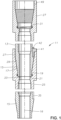
- tubular member connection system 11 includes a first or upper tubular member 13 with pin 15 formed on an end of upper tubular member 13.
- the terms “upper” and “lower” are used only for convenience as pin 15 could be located on the upper end of tubular member 13 if the tubular member is inverted.
- Pin 15 has a longitudinal central axis 16 and external pin threads 17 located on a conical outer diameter surface.
- Pin 15 has a nose 19 on a first end of pin 15 that is located on an axially outer side of pin threads 17.
- Pin lip 21 is an annular surface at an end surface of nose 19 of pin 15.
- Upper tubular member 13 extends from pin 15 in a direction opposite nose 19 of pin 15.
- Tubular member connection system 11 also includes a second or lower tubular member 25 with box 27 formed on an end of lower tubular member 25.
- Box 27 has internal box threads 29 located on an inner diameter surface of box 27. Box threads 29 are shaped to mate with pin threads 17 to releasably secure pin 15 to box 27 so that pin 15 and box 27 are aligned along common central axis 16.
- Box 27 has annular box shoulder 31 on the inner diameter surface of box 27. Box shoulder 31 faces towards an open end or first end of box 27. Box shoulder 31 is sized to mate with pin lip 21 when pin 15 is threaded into box 27.
- Lower tubular member 25 extends from box 27 in a direction opposite box shoulder 31.
- Upper tubular member 13 can have a second box 27 at an opposite end of upper tubular member 13 from pin 15 and lower tubular member 25 can have a second pin 15 at an opposite end of lower tubular member from box.
- a pin 15 of a next or adjacent tubular member can be releasably secured to box 27 of upper tubular member 13 to form a tubular string.
- a box 27 of a prior or adjacent tubular member can be releasably secured to pin 15 of lower tubular member 25.
- Upper tubular member 13 and pin 15 as well as lower tubular member and box 27 can all include an inner bore 33.
- Inner bore 33 of upper tubular member 13, pin 15, lower tubular member, and box 27 can fluidly register with each other and can be used to transfer fluids and associated matter along a length of the tubular string.
- Slot 35 can be formed in the inner diameter surface of box 27 or the outer diameter surface of pin 15.
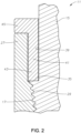
- slot 35 is formed in the outer diameter surface of pin 15 and extends radially inward from the outer diameter surface of pin 15. Slot 35 extends generally parallel to central axis 16. Slot 35 has a pair of sidewalls 37 that extend generally parallel to central axis 16 and define the side surfaces of slot 35. A slot bottom extends between sidewalls 37. Slot 35 has a radial depth that is less than the thickness of the sidewall of pin 15 so that slot 35 has a back wall 39 ( Figure 2 ). Slot 35 can have planar sidewalls 37 and a planar back wall 39. In alternate embodiments, back wall 39 can be curved, for example having a similar curvature as the outer diameter surface of the outer diameter surface of pin 15 or the inner diameter surface of box 27.
- key 41 can be sized to fit within slot 35.
- a width W of key 41 can be slightly smaller than distance D between sidewalls 37 of slot 35 so that key 41 can slide easily into slot 35.
- Sidewalls 37 of slot 35 can engage sides of key 41 so that key 41 has limited circumferential movement within slot 35.
- Retainer 42 ( Figure 1 ) can be used to ensure that key 41 remains within slot 35.
- Retainer 42 can be a screw, a latch, or other type of fastener or retaining mechanism.
- key 41 can include a main key body 43 and key profile 45.
- Key body 43 and key profile 45 can be a single integrated member or alternately, key profile 45 can be one or more separate members that are secured to key body 43.
- key profile 45 extends radially outward from key body 43 and includes a plurality of protrusions.
- slot 35 is located on the inner diameter surface of box 27, key profile 45 can instead extend radially inward from key body 43.
- the protrusions of the example configuration are generally square shaped.
- key profile 45 can have other shapes, such as rectangular, shaped members.
- a back face of key 41 can be planar or in alternate embodiments the back face of key 41 can be a curved surface, as applicable, to match the shape of back wall 39 of slot 35.
- Anti-rotation profile 47 can be located on an opposite surface to slot 35.
- anti-rotation profile 47 is in an inner diameter surface of box 27.
- anti-rotation profile 47 can be in an outer diameter surface of pin 15.
- anti-rotation profile 47 can engage key profile 45 to prevent relative rotational movement between box 27 and key 41. The relative rotational loads will be transferred between anti-rotation profile 47 and key profile 45, and to sidewalls 37 of slot 35.
- anti-rotation profile 47 includes a series of grooves 49. Grooves 49 can extend through a sidewall of box 27, starting from the open end of box 27. In alternate embodiments, grooves 49 can extend into the sidewall of box 27 but not extend all the way through the sidewall of box 27.
- Slot 35 is located on pin 15 in a position such that each of the plurality of protrusions of key profile 45 can engage one of the grooves 49 when pin 15 is threaded into box 27 until pin lip 21 engages box shoulder 31.
- the location of slot 35 can be pre-determined by clocking the final made-up position of either slot 35 or anti-rotation profile 47 or both. This clocking procedure can be completed by making up pin 15 with a dummy box that has an identical configuration of box threads 29 and relative location of anti-rotation profile 47 as actual box 27. Due to this clocking procedure to determine the position of slot 35 on pin 15, each of the protrusions of key profile 45 can engage one of the grooves 49 of anti-rotation profile 47 when pin 15 is threaded to box 27 to a fully made-up position.
- the number of protrusions of key profile 45 is less than the number of grooves of anti-rotation profile 47.
- the number of empty grooves on either side of key 41 can be as few as zero or can be two or more .
- width W of key 41 and distance D between sidewalls 37 of slot 35 allows key profile 45 to be placed in a range of locations in slot 35 to allow key profile 45 to engage anti-rotation profile 47, after the threaded connection has been made up between pin 15 and box 27.
- box 27 can be provided on lower tubular member 25.
- Anti-rotation profile 47 can be formed on an inner diameter surface of box 27.
- anti-rotation profile 47 can be a series of grooves machined into or entirely through a sidewall of box 27.
- Pin 15 can be provided on upper tubular member 13.
- Slot 35 can be formed in an outer diameter surface of pin 15, such as by machining slot 35 in pin 15. The location of slot 35 can be clocked so that slot 35 will align with anti-rotation profile 47 when pin 15 and box 27 are fully made-up.
- pin 15 Nose 19 of pin 15 can then be located within box 27 and pin 15 can be rotated so that box threads 29 can mate with pin threads 17.
- Pin 15 can be threaded to box 27 in a make-up rotation direction until pin lip 21 engages box shoulder 31.
- key 41 can be inserted into slot 35.
- Key 41 is inserted into slot 35 by simply sliding key 41 into slot 35 in an axial direction. No special tools or significant force is required to slide key 41 into slot 35. Sliding key 41 into slot 35 can be done by an operator by hand.
- Slot 35 has a sufficient axial height that key 41 can easily enter slot 35. No material of pin 15, box 27, or key 41 is required to be deformed or cut during the step of sliding key 41 into slot 35.
- a bottom end of key body 43 can enter slot 35 first.
- protrusions of key profile 45 can be rotationally aligned with grooves 49 of anti-rotation profile 47 so that protrusions of key profile 45 can enter into grooves 49.
- the interaction of key profile 45 with grooves 49 of anti-rotation profile 47, together with the engagement of a side of key 41 with a sidewall 37 of slot 35 will restrict relative rotation between pin 15 and box 27.
- Retainer 42 can be inserted so that key 41 remains within slot 35.
- Tubular member connection system 11 may not need to be unscrewed once made up. On some occasions, however, the operator might wish to unscrew tubular member connection system 11. In such a case, an operator can manually remove retainer 42 then key 41 and pin 15 can be rotated relative to box 27 in an unscrewing direction to release pin 15 from box 27 so that upper tubular member 13 can be separated from lower tubular member 25.
Landscapes
- Engineering & Computer Science (AREA)
- Mining & Mineral Resources (AREA)
- Life Sciences & Earth Sciences (AREA)
- Geology (AREA)
- Mechanical Engineering (AREA)
- General Engineering & Computer Science (AREA)
- Fluid Mechanics (AREA)
- Environmental & Geological Engineering (AREA)
- Physics & Mathematics (AREA)
- General Life Sciences & Earth Sciences (AREA)
- Geochemistry & Mineralogy (AREA)
- Quick-Acting Or Multi-Walled Pipe Joints (AREA)
- Management, Administration, Business Operations System, And Electronic Commerce (AREA)
- Financial Or Insurance-Related Operations Such As Payment And Settlement (AREA)
Claims (14)
- Système de liaison d'élément tubulaire (11), comprenant :une boîte (27) ayant une surface de diamètre interne, des filets de boîte intérieurs (29), et un épaulement de boîte annulaire (31) sur la surface de diamètre interne de la boîte ;une broche (15) ayant une surface de diamètre externe, des filets de broche extérieurs (17), et une lèvre de broche annulaire (21) au niveau d'une surface d'extrémité de la broche, les filets de broche (17) formés pour s'accoupler avec les filets de boîte (29) pour fixer de manière amovible la broche (15) à la boîte (27) de sorte que la broche (15) et la boîte (27) sont alignées le long d'un axe central commun ;une fente (35) dans l'une de la surface de diamètre interne et de la surface de diamètre externe, la fente ayant une paire de parois latérales (37) ;un profil anti-rotation (47) dans l'autre de la surface de diamètre interne et de la surface de diamètre externe ; etune clavette (41) dimensionnée pour s'adapter à l'intérieur de la fente (35) et ayant un profil de clavette (45) formé pour venir en prise avec le profil anti-rotation (47) et empêcher un mouvement de rotation relatif entre la boîte (27) et la broche (15) ;caractérisé en ce que le profil anti-rotation (47) comporte une pluralité de rainures (49) et le profil de clavette (45) comporte une pluralité de saillies de forme rectangulaire localisées pour tomber à l'intérieur de la pluralité de rainures (49).
- Système selon la revendication 1, dans lequel un nombre de rainures (49) est supérieur à un nombre de saillies.
- Système selon la revendication 1 ou la revendication 2, dans lequel la fente (35) s'étend généralement parallèle à l'axe central.
- Système selon l'une quelconque revendication précédente, dans lequel la fente (35) est positionnée de telle sorte que la fente s'aligne radialement avec le profil anti-rotation (47) lorsque la broche (15) est filetée sur la boîte (27) jusqu'à ce que la lèvre de broche (21) vienne en prise avec l'épaulement de boîte (31).
- Système selon l'une quelconque revendication précédente, dans lequel la fente (35) s'étend radialement vers l'intérieur depuis la surface de diamètre externe de la broche (15).
- Système selon l'une quelconque revendication précédente, dans lequel le profil anti-rotation (47) comporte une pluralité de rainures (49) s'étendant radialement à travers une paroi latérale de la boîte (27) depuis une extrémité de la boîte.
- Système selon l'une quelconque revendication précédente, comprenant en outre :un premier élément tubulaire (13) s'étendant depuis la broche (15) dans une direction opposée à la première extrémité de la broche ;un second élément tubulaire (25) s'étendant depuis la boîte (27) dans une direction opposée à l'épaulement de boîte (31).
- Système selon l'une quelconque revendication précédente, dans lequel chaque saillie vient en prise avec l'une des rainures (49) lorsque la clavette (41) est localisée dans la fente (35).
- Système selon la revendication 7, dans lequel le premier élément tubulaire (13) a une seconde boîte au niveau d'une extrémité opposée du premier élément tubulaire depuis la broche (15), la seconde boîte étant fixée de manière amovible à une seconde broche pour former une colonne tubulaire.
- Système selon l'une quelconque des revendications précédentes, dans lequel les saillies sont en forme de carré.
- Procédé pour la liaison d'éléments tubulaires (13, 15), le procédé comprenant :la fourniture d'une boîte (27) ayant une surface de diamètre interne, des filets de boîte intérieurs (29), et un épaulement de boîte annulaire (31) sur la surface de diamètre interne de la boîte ;la fourniture d'une broche (15) ayant une surface de diamètre externe, des filets de broche extérieurs (17), et une lèvre de broche annulaire (21) au niveau d'une surface d'extrémité de la broche,l'accouplement des filets de broche (17) avec les filets de boîte (29) pour fixer de manière amovible la broche (15) à la boîte (27) de sorte que la broche (15) et la boîte (27) sont alignées le long d'un axe central commun ; etla localisation d'une clavette (41) à l'intérieur d'une fente (35) de sorte qu'un profil de clavette (45) de la clavette vient en prise avec un profil anti-rotation (47) et empêche un mouvement de rotation relatif entre la boîte (27) et la broche (15) ; dans lequella fente (35) est localisée dans l'une de la surface de diamètre interne et de la surface de diamètre externe et le profil anti-rotation (47) est localisé dans l'autre de la surface de diamètre interne et de la surface de diamètre externe ; etdans lequel le profil anti-rotation (47) comporte une pluralité de rainures (49) et le profil de clavette (45) comporte une pluralité de saillies de forme rectangulaire et la localisation de la clavette (41) à l'intérieur de la fente (35) comporte le fait de tomber les saillies à l'intérieur de la pluralité de rainures (49).
- Procédé selon la revendication 11, dans lequel un nombre de saillies est inférieur à un nombre de rainures (49), et dans lequel la localisation de la clavette (41) à l'intérieur de la fente (35) comporte la localisation de chaque saillie à l'intérieur d'une des rainures (49).
- Procédé selon la revendication 11 ou la revendication 12, dans lequel le profil anti-rotation (47) comporte une pluralité de rainures (49) s'étendant radialement à travers une paroi latérale de la boîte (27) depuis une extrémité de la boîte.
- Procédé selon l'une quelconque des revendications 11 à 13, dans lequel les saillies sont en forme de carré.
Applications Claiming Priority (2)
| Application Number | Priority Date | Filing Date | Title |
|---|---|---|---|
| US15/151,032 US10605012B2 (en) | 2016-05-10 | 2016-05-10 | Drop in anti-rotation key |
| PCT/US2017/027882 WO2017196499A1 (fr) | 2016-05-10 | 2017-04-17 | Chute dans une clef anti-rotation |
Publications (2)
| Publication Number | Publication Date |
|---|---|
| EP3455448A1 EP3455448A1 (fr) | 2019-03-20 |
| EP3455448B1 true EP3455448B1 (fr) | 2023-05-31 |
Family
ID=59215903
Family Applications (1)
| Application Number | Title | Priority Date | Filing Date |
|---|---|---|---|
| EP17733123.8A Active EP3455448B1 (fr) | 2016-05-10 | 2017-04-17 | Chute dans une clef anti-rotation |
Country Status (5)
| Country | Link |
|---|---|
| US (1) | US10605012B2 (fr) |
| EP (1) | EP3455448B1 (fr) |
| BR (1) | BR112018072469B1 (fr) |
| SG (1) | SG11201809715SA (fr) |
| WO (1) | WO2017196499A1 (fr) |
Families Citing this family (5)
| Publication number | Priority date | Publication date | Assignee | Title |
|---|---|---|---|---|
| US11680493B2 (en) | 2018-06-19 | 2023-06-20 | Raytheon Technologies Corporation | Anti-rotation pin for compression fitting |
| US11459833B2 (en) | 2020-07-07 | 2022-10-04 | Baker Hughes Oilfield Operations Llc | System and method for anti-rotation between tubulars |
| US11512799B2 (en) * | 2020-07-07 | 2022-11-29 | Baker Hughes Oilfield Operations Llc | System and method for anti-rotation between tubulars |
| ES2942899T3 (es) * | 2020-12-18 | 2023-06-07 | Danfoss As | Conjunto de tubos, intercambiador de presión y sistema de ósmosis inversa |
| AU2024327088A1 (en) | 2023-08-18 | 2026-03-19 | Noetic Technologies Inc. | Locking threaded connection assembly |
Family Cites Families (16)
| Publication number | Priority date | Publication date | Assignee | Title |
|---|---|---|---|---|
| US2440257A (en) * | 1946-09-07 | 1948-04-27 | Anthony J Keel | Safety joint |
| US3948545A (en) * | 1974-03-11 | 1976-04-06 | Mcevoy Oilfield Equipment Co. | Mechanically operated breech block |
| US4261599A (en) | 1978-10-12 | 1981-04-14 | Koch Fiberglass Products Co. | Joint for connecting pipes |
| FR2524112A1 (fr) | 1982-03-29 | 1983-09-30 | Vallourec | Joint tubulaire filete muni d'un dispositif de freinage |
| US4902047A (en) * | 1989-04-14 | 1990-02-20 | Vetco Gray Inc. | Thread connector anti-rotation device |
| US5785357A (en) * | 1995-09-22 | 1998-07-28 | Utd, Inc. | Locking joint |
| NO20034158L (no) * | 2003-09-18 | 2005-03-21 | Hydralift Asa | Laseanordning av sammenskrudd rorforbindelse |
| US7146704B2 (en) | 2004-05-20 | 2006-12-12 | Grant Prideco, L.P. | Method for coupling connectors using an anti-rotation device |
| GB0805719D0 (en) * | 2008-03-29 | 2008-04-30 | Petrowell Ltd | Improved tubing section coupling |
| US8474876B2 (en) * | 2010-04-22 | 2013-07-02 | Vetco Gray Inc. | Cam style anti-rotation key for tubular connections |
| US9410647B2 (en) * | 2012-10-12 | 2016-08-09 | Vetco Gray Inc. | Anti-rotation system for box and pin connection |
| US9714731B2 (en) * | 2012-10-12 | 2017-07-25 | Vetco Gray Inc. | Threaded connector locking device |
| US8950785B2 (en) * | 2012-11-08 | 2015-02-10 | Vetco Gray Inc. | Broach style anti rotation device for connectors |
| US8690200B1 (en) * | 2012-12-13 | 2014-04-08 | Vetco Gray Inc. | Radially-inserted anti-rotation key for threaded connectors |
| US9708865B2 (en) * | 2012-12-13 | 2017-07-18 | Vetco Gray Inc. | Ratcheting anti-rotation lock for threaded connectors |
| US9890598B2 (en) | 2012-12-17 | 2018-02-13 | Vetco Gray Inc. | Anti-rotation wedge |
-
2016
- 2016-05-10 US US15/151,032 patent/US10605012B2/en active Active
-
2017
- 2017-04-17 BR BR112018072469-6A patent/BR112018072469B1/pt active IP Right Grant
- 2017-04-17 WO PCT/US2017/027882 patent/WO2017196499A1/fr not_active Ceased
- 2017-04-17 EP EP17733123.8A patent/EP3455448B1/fr active Active
- 2017-04-17 SG SG11201809715SA patent/SG11201809715SA/en unknown
Also Published As
| Publication number | Publication date |
|---|---|
| US10605012B2 (en) | 2020-03-31 |
| SG11201809715SA (en) | 2018-11-29 |
| WO2017196499A1 (fr) | 2017-11-16 |
| BR112018072469A2 (pt) | 2019-02-19 |
| BR112018072469B1 (pt) | 2023-01-17 |
| EP3455448A1 (fr) | 2019-03-20 |
| US20170328138A1 (en) | 2017-11-16 |
Similar Documents
| Publication | Publication Date | Title |
|---|---|---|
| EP3310990B1 (fr) | Clé anti-rotation pour raccords filetés | |
| US10597950B2 (en) | Pre-installed anti-rotation key for threaded connectors | |
| EP3455448B1 (fr) | Chute dans une clef anti-rotation | |
| US8690200B1 (en) | Radially-inserted anti-rotation key for threaded connectors | |
| US4648627A (en) | Stabbing connector | |
| US7434848B2 (en) | Threaded tubular connection having interlocking tubular end structures | |
| US8505637B2 (en) | System and method for forming a coiled tubing connection | |
| US8474876B2 (en) | Cam style anti-rotation key for tubular connections | |
| US20150107856A1 (en) | Slip assembly | |
| CN103582739A (zh) | 管状连接装置和相关的螺纹牙型 | |
| RU2760380C2 (ru) | Горная буровая система с переходником | |
| US11421499B2 (en) | Actuator ring lock packoff assembly with interlocking mandrel hanger | |
| US10422190B2 (en) | Quick connect connection | |
| US20060267342A1 (en) | Tubular connection and method | |
| CN113396300A (zh) | 钢管用螺纹接头 | |
| US20200011140A1 (en) | Coupling assembly for elongate elements | |
| US10815737B1 (en) | Tool joint clamp | |
| GB2559888A (en) | System and method | |
| US10753160B2 (en) | Well tool device | |
| HK1193858B (en) | Tubular connection and associated thread form | |
| HK1193858A (en) | Tubular connection and associated thread form | |
| GB2487946A (en) | Anti rotation pipe connector for downhole casing joints |
Legal Events
| Date | Code | Title | Description |
|---|---|---|---|
| STAA | Information on the status of an ep patent application or granted ep patent |
Free format text: STATUS: UNKNOWN |
|
| STAA | Information on the status of an ep patent application or granted ep patent |
Free format text: STATUS: THE INTERNATIONAL PUBLICATION HAS BEEN MADE |
|
| PUAI | Public reference made under article 153(3) epc to a published international application that has entered the european phase |
Free format text: ORIGINAL CODE: 0009012 |
|
| STAA | Information on the status of an ep patent application or granted ep patent |
Free format text: STATUS: REQUEST FOR EXAMINATION WAS MADE |
|
| 17P | Request for examination filed |
Effective date: 20181210 |
|
| AK | Designated contracting states |
Kind code of ref document: A1 Designated state(s): AL AT BE BG CH CY CZ DE DK EE ES FI FR GB GR HR HU IE IS IT LI LT LU LV MC MK MT NL NO PL PT RO RS SE SI SK SM TR |
|
| AX | Request for extension of the european patent |
Extension state: BA ME |
|
| DAV | Request for validation of the european patent (deleted) | ||
| DAX | Request for extension of the european patent (deleted) | ||
| STAA | Information on the status of an ep patent application or granted ep patent |
Free format text: STATUS: EXAMINATION IS IN PROGRESS |
|
| 17Q | First examination report despatched |
Effective date: 20200115 |
|
| GRAP | Despatch of communication of intention to grant a patent |
Free format text: ORIGINAL CODE: EPIDOSNIGR1 |
|
| STAA | Information on the status of an ep patent application or granted ep patent |
Free format text: STATUS: GRANT OF PATENT IS INTENDED |
|
| INTG | Intention to grant announced |
Effective date: 20230214 |
|
| GRAS | Grant fee paid |
Free format text: ORIGINAL CODE: EPIDOSNIGR3 |
|
| GRAA | (expected) grant |
Free format text: ORIGINAL CODE: 0009210 |
|
| STAA | Information on the status of an ep patent application or granted ep patent |
Free format text: STATUS: THE PATENT HAS BEEN GRANTED |
|
| AK | Designated contracting states |
Kind code of ref document: B1 Designated state(s): AL AT BE BG CH CY CZ DE DK EE ES FI FR GB GR HR HU IE IS IT LI LT LU LV MC MK MT NL NO PL PT RO RS SE SI SK SM TR |
|
| REG | Reference to a national code |
Ref country code: GB Ref legal event code: FG4D Ref country code: CH Ref legal event code: EP |
|
| REG | Reference to a national code |
Ref country code: DE Ref legal event code: R096 Ref document number: 602017069204 Country of ref document: DE |
|
| REG | Reference to a national code |
Ref country code: AT Ref legal event code: REF Ref document number: 1571006 Country of ref document: AT Kind code of ref document: T Effective date: 20230615 |
|
| REG | Reference to a national code |
Ref country code: IE Ref legal event code: FG4D |
|
| P01 | Opt-out of the competence of the unified patent court (upc) registered |
Effective date: 20230526 |
|
| REG | Reference to a national code |
Ref country code: LT Ref legal event code: MG9D |
|
| REG | Reference to a national code |
Ref country code: NL Ref legal event code: MP Effective date: 20230531 |
|
| REG | Reference to a national code |
Ref country code: AT Ref legal event code: MK05 Ref document number: 1571006 Country of ref document: AT Kind code of ref document: T Effective date: 20230531 |
|
| PG25 | Lapsed in a contracting state [announced via postgrant information from national office to epo] |
Ref country code: SE Free format text: LAPSE BECAUSE OF FAILURE TO SUBMIT A TRANSLATION OF THE DESCRIPTION OR TO PAY THE FEE WITHIN THE PRESCRIBED TIME-LIMIT Effective date: 20230531 Ref country code: NO Free format text: LAPSE BECAUSE OF FAILURE TO SUBMIT A TRANSLATION OF THE DESCRIPTION OR TO PAY THE FEE WITHIN THE PRESCRIBED TIME-LIMIT Effective date: 20230831 Ref country code: ES Free format text: LAPSE BECAUSE OF FAILURE TO SUBMIT A TRANSLATION OF THE DESCRIPTION OR TO PAY THE FEE WITHIN THE PRESCRIBED TIME-LIMIT Effective date: 20230531 Ref country code: AT Free format text: LAPSE BECAUSE OF FAILURE TO SUBMIT A TRANSLATION OF THE DESCRIPTION OR TO PAY THE FEE WITHIN THE PRESCRIBED TIME-LIMIT Effective date: 20230531 |
|
| PG25 | Lapsed in a contracting state [announced via postgrant information from national office to epo] |
Ref country code: RS Free format text: LAPSE BECAUSE OF FAILURE TO SUBMIT A TRANSLATION OF THE DESCRIPTION OR TO PAY THE FEE WITHIN THE PRESCRIBED TIME-LIMIT Effective date: 20230531 Ref country code: PL Free format text: LAPSE BECAUSE OF FAILURE TO SUBMIT A TRANSLATION OF THE DESCRIPTION OR TO PAY THE FEE WITHIN THE PRESCRIBED TIME-LIMIT Effective date: 20230531 Ref country code: NL Free format text: LAPSE BECAUSE OF FAILURE TO SUBMIT A TRANSLATION OF THE DESCRIPTION OR TO PAY THE FEE WITHIN THE PRESCRIBED TIME-LIMIT Effective date: 20230531 Ref country code: LV Free format text: LAPSE BECAUSE OF FAILURE TO SUBMIT A TRANSLATION OF THE DESCRIPTION OR TO PAY THE FEE WITHIN THE PRESCRIBED TIME-LIMIT Effective date: 20230531 Ref country code: LT Free format text: LAPSE BECAUSE OF FAILURE TO SUBMIT A TRANSLATION OF THE DESCRIPTION OR TO PAY THE FEE WITHIN THE PRESCRIBED TIME-LIMIT Effective date: 20230531 Ref country code: IS Free format text: LAPSE BECAUSE OF FAILURE TO SUBMIT A TRANSLATION OF THE DESCRIPTION OR TO PAY THE FEE WITHIN THE PRESCRIBED TIME-LIMIT Effective date: 20230930 Ref country code: HR Free format text: LAPSE BECAUSE OF FAILURE TO SUBMIT A TRANSLATION OF THE DESCRIPTION OR TO PAY THE FEE WITHIN THE PRESCRIBED TIME-LIMIT Effective date: 20230531 Ref country code: GR Free format text: LAPSE BECAUSE OF FAILURE TO SUBMIT A TRANSLATION OF THE DESCRIPTION OR TO PAY THE FEE WITHIN THE PRESCRIBED TIME-LIMIT Effective date: 20230901 |
|
| PG25 | Lapsed in a contracting state [announced via postgrant information from national office to epo] |
Ref country code: FI Free format text: LAPSE BECAUSE OF FAILURE TO SUBMIT A TRANSLATION OF THE DESCRIPTION OR TO PAY THE FEE WITHIN THE PRESCRIBED TIME-LIMIT Effective date: 20230531 |
|
| PG25 | Lapsed in a contracting state [announced via postgrant information from national office to epo] |
Ref country code: SK Free format text: LAPSE BECAUSE OF FAILURE TO SUBMIT A TRANSLATION OF THE DESCRIPTION OR TO PAY THE FEE WITHIN THE PRESCRIBED TIME-LIMIT Effective date: 20230531 |
|
| PG25 | Lapsed in a contracting state [announced via postgrant information from national office to epo] |
Ref country code: SM Free format text: LAPSE BECAUSE OF FAILURE TO SUBMIT A TRANSLATION OF THE DESCRIPTION OR TO PAY THE FEE WITHIN THE PRESCRIBED TIME-LIMIT Effective date: 20230531 Ref country code: SK Free format text: LAPSE BECAUSE OF FAILURE TO SUBMIT A TRANSLATION OF THE DESCRIPTION OR TO PAY THE FEE WITHIN THE PRESCRIBED TIME-LIMIT Effective date: 20230531 Ref country code: RO Free format text: LAPSE BECAUSE OF FAILURE TO SUBMIT A TRANSLATION OF THE DESCRIPTION OR TO PAY THE FEE WITHIN THE PRESCRIBED TIME-LIMIT Effective date: 20230531 Ref country code: PT Free format text: LAPSE BECAUSE OF FAILURE TO SUBMIT A TRANSLATION OF THE DESCRIPTION OR TO PAY THE FEE WITHIN THE PRESCRIBED TIME-LIMIT Effective date: 20231002 Ref country code: EE Free format text: LAPSE BECAUSE OF FAILURE TO SUBMIT A TRANSLATION OF THE DESCRIPTION OR TO PAY THE FEE WITHIN THE PRESCRIBED TIME-LIMIT Effective date: 20230531 Ref country code: DK Free format text: LAPSE BECAUSE OF FAILURE TO SUBMIT A TRANSLATION OF THE DESCRIPTION OR TO PAY THE FEE WITHIN THE PRESCRIBED TIME-LIMIT Effective date: 20230531 Ref country code: CZ Free format text: LAPSE BECAUSE OF FAILURE TO SUBMIT A TRANSLATION OF THE DESCRIPTION OR TO PAY THE FEE WITHIN THE PRESCRIBED TIME-LIMIT Effective date: 20230531 |
|
| REG | Reference to a national code |
Ref country code: DE Ref legal event code: R097 Ref document number: 602017069204 Country of ref document: DE |
|
| PLBE | No opposition filed within time limit |
Free format text: ORIGINAL CODE: 0009261 |
|
| STAA | Information on the status of an ep patent application or granted ep patent |
Free format text: STATUS: NO OPPOSITION FILED WITHIN TIME LIMIT |
|
| PG25 | Lapsed in a contracting state [announced via postgrant information from national office to epo] |
Ref country code: SI Free format text: LAPSE BECAUSE OF FAILURE TO SUBMIT A TRANSLATION OF THE DESCRIPTION OR TO PAY THE FEE WITHIN THE PRESCRIBED TIME-LIMIT Effective date: 20230531 |
|
| 26N | No opposition filed |
Effective date: 20240301 |
|
| PG25 | Lapsed in a contracting state [announced via postgrant information from national office to epo] |
Ref country code: SI Free format text: LAPSE BECAUSE OF FAILURE TO SUBMIT A TRANSLATION OF THE DESCRIPTION OR TO PAY THE FEE WITHIN THE PRESCRIBED TIME-LIMIT Effective date: 20230531 Ref country code: IT Free format text: LAPSE BECAUSE OF FAILURE TO SUBMIT A TRANSLATION OF THE DESCRIPTION OR TO PAY THE FEE WITHIN THE PRESCRIBED TIME-LIMIT Effective date: 20230531 |
|
| REG | Reference to a national code |
Ref country code: DE Ref legal event code: R119 Ref document number: 602017069204 Country of ref document: DE |
|
| PG25 | Lapsed in a contracting state [announced via postgrant information from national office to epo] |
Ref country code: BG Free format text: LAPSE BECAUSE OF FAILURE TO SUBMIT A TRANSLATION OF THE DESCRIPTION OR TO PAY THE FEE WITHIN THE PRESCRIBED TIME-LIMIT Effective date: 20230531 |
|
| PG25 | Lapsed in a contracting state [announced via postgrant information from national office to epo] |
Ref country code: MC Free format text: LAPSE BECAUSE OF FAILURE TO SUBMIT A TRANSLATION OF THE DESCRIPTION OR TO PAY THE FEE WITHIN THE PRESCRIBED TIME-LIMIT Effective date: 20230531 |
|
| PG25 | Lapsed in a contracting state [announced via postgrant information from national office to epo] |
Ref country code: MC Free format text: LAPSE BECAUSE OF FAILURE TO SUBMIT A TRANSLATION OF THE DESCRIPTION OR TO PAY THE FEE WITHIN THE PRESCRIBED TIME-LIMIT Effective date: 20230531 Ref country code: BG Free format text: LAPSE BECAUSE OF FAILURE TO SUBMIT A TRANSLATION OF THE DESCRIPTION OR TO PAY THE FEE WITHIN THE PRESCRIBED TIME-LIMIT Effective date: 20230531 |
|
| REG | Reference to a national code |
Ref country code: CH Ref legal event code: PL |
|
| PG25 | Lapsed in a contracting state [announced via postgrant information from national office to epo] |
Ref country code: LU Free format text: LAPSE BECAUSE OF NON-PAYMENT OF DUE FEES Effective date: 20240417 |
|
| REG | Reference to a national code |
Ref country code: BE Ref legal event code: MM Effective date: 20240430 |
|
| PG25 | Lapsed in a contracting state [announced via postgrant information from national office to epo] |
Ref country code: LU Free format text: LAPSE BECAUSE OF NON-PAYMENT OF DUE FEES Effective date: 20240417 |
|
| PG25 | Lapsed in a contracting state [announced via postgrant information from national office to epo] |
Ref country code: DE Free format text: LAPSE BECAUSE OF NON-PAYMENT OF DUE FEES Effective date: 20241105 |
|
| PG25 | Lapsed in a contracting state [announced via postgrant information from national office to epo] |
Ref country code: BE Free format text: LAPSE BECAUSE OF NON-PAYMENT OF DUE FEES Effective date: 20240430 |
|
| PG25 | Lapsed in a contracting state [announced via postgrant information from national office to epo] |
Ref country code: FR Free format text: LAPSE BECAUSE OF NON-PAYMENT OF DUE FEES Effective date: 20240430 |
|
| PG25 | Lapsed in a contracting state [announced via postgrant information from national office to epo] |
Ref country code: FR Free format text: LAPSE BECAUSE OF NON-PAYMENT OF DUE FEES Effective date: 20240430 Ref country code: DE Free format text: LAPSE BECAUSE OF NON-PAYMENT OF DUE FEES Effective date: 20241105 Ref country code: BE Free format text: LAPSE BECAUSE OF NON-PAYMENT OF DUE FEES Effective date: 20240430 Ref country code: CH Free format text: LAPSE BECAUSE OF NON-PAYMENT OF DUE FEES Effective date: 20240430 |
|
| PG25 | Lapsed in a contracting state [announced via postgrant information from national office to epo] |
Ref country code: IE Free format text: LAPSE BECAUSE OF NON-PAYMENT OF DUE FEES Effective date: 20240417 |
|
| PG25 | Lapsed in a contracting state [announced via postgrant information from national office to epo] |
Ref country code: CY Free format text: LAPSE BECAUSE OF FAILURE TO SUBMIT A TRANSLATION OF THE DESCRIPTION OR TO PAY THE FEE WITHIN THE PRESCRIBED TIME-LIMIT; INVALID AB INITIO Effective date: 20170417 |
|
| PG25 | Lapsed in a contracting state [announced via postgrant information from national office to epo] |
Ref country code: HU Free format text: LAPSE BECAUSE OF FAILURE TO SUBMIT A TRANSLATION OF THE DESCRIPTION OR TO PAY THE FEE WITHIN THE PRESCRIBED TIME-LIMIT; INVALID AB INITIO Effective date: 20170417 |
|
| PGFP | Annual fee paid to national office [announced via postgrant information from national office to epo] |
Ref country code: GB Payment date: 20260319 Year of fee payment: 10 |