EP3455457B1 - Procédés et systèmes pour optimiser une opération de forage en fonction de multiples mesures de formation - Google Patents
Procédés et systèmes pour optimiser une opération de forage en fonction de multiples mesures de formation Download PDFInfo
- Publication number
- EP3455457B1 EP3455457B1 EP17796621.5A EP17796621A EP3455457B1 EP 3455457 B1 EP3455457 B1 EP 3455457B1 EP 17796621 A EP17796621 A EP 17796621A EP 3455457 B1 EP3455457 B1 EP 3455457B1
- Authority
- EP
- European Patent Office
- Prior art keywords
- formation
- formation characteristic
- wellbore
- model
- drilling
- Prior art date
- Legal status (The legal status is an assumption and is not a legal conclusion. Google has not performed a legal analysis and makes no representation as to the accuracy of the status listed.)
- Active
Links
Images


Classifications
-
- E—FIXED CONSTRUCTIONS
- E21—EARTH OR ROCK DRILLING; MINING
- E21B—EARTH OR ROCK DRILLING; OBTAINING OIL, GAS, WATER, SOLUBLE OR MELTABLE MATERIALS OR A SLURRY OF MINERALS FROM WELLS
- E21B44/00—Automatic control systems specially adapted for drilling operations, i.e. self-operating systems which function to carry out or modify a drilling operation without intervention of a human operator, e.g. computer-controlled drilling systems; Systems specially adapted for monitoring a plurality of drilling variables or conditions
-
- E—FIXED CONSTRUCTIONS
- E21—EARTH OR ROCK DRILLING; MINING
- E21B—EARTH OR ROCK DRILLING; OBTAINING OIL, GAS, WATER, SOLUBLE OR MELTABLE MATERIALS OR A SLURRY OF MINERALS FROM WELLS
- E21B49/00—Testing the nature of borehole walls; Formation testing; Methods or apparatus for obtaining samples of soil or well fluids, specially adapted to earth drilling or wells
- E21B49/003—Testing the nature of borehole walls; Formation testing; Methods or apparatus for obtaining samples of soil or well fluids, specially adapted to earth drilling or wells by analysing drilling variables or conditions
-
- E—FIXED CONSTRUCTIONS
- E21—EARTH OR ROCK DRILLING; MINING
- E21B—EARTH OR ROCK DRILLING; OBTAINING OIL, GAS, WATER, SOLUBLE OR MELTABLE MATERIALS OR A SLURRY OF MINERALS FROM WELLS
- E21B7/00—Special methods or apparatus for drilling
- E21B7/04—Directional drilling
Definitions
- WO2009129060A1 discloses drilling operations based on a pre-constructed formation model.
- Amer et al. (Oilfield Review 25.1 (2013): 14-31 ) discloses examples of real world drilling operations.
- Embodiments of the present disclosure relate to navigating a wellbore through a reservoir by means of conducting multiple measurements and interpreting the measurements to characterize the reservoir around the wellbore in order to make steering decisions. More specifically, embodiments provided herein involve conducting a resistivity, electromagnetic, or acoustic measurement to determine reservoir architecture around the wellbore and conducting a hydraulic test using a formation testing tool. The hydraulic test results are analyzed to constrain the reservoir architecture around the wellbore (e.g., as obtained from the resistivity electromagnetic, or acoustic measurements).
- Embodiments provided herein provide a way that the combined interpretation of hydraulic tests and acoustic, electromagnetic, and resistivity data can be used to reduce uncertainty of the formation and reservoir properties around the wellbore. Whereas one isolated measurement can be explained by a large number of formation models, this combination reduces the amount of models which are able to explain all acquired data. Fitting between the model and the measurements can be either conducted automatically using appropriate inversion algorithms or manually by adjusting the model parameters (forward modeling).
- FIG. 1 shows a schematic diagram of a drilling system 10 that includes a drill string 20 having a drilling assembly 90, also referred to as a bottomhole assembly (BHA), conveyed in a wellbore 26 penetrating an earth formation 60.
- the drilling system 10 includes a conventional derrick 11 erected on a floor 12 that supports a rotary table 14 that is rotated by a prime mover, such as an electric motor (not shown), at a desired rotational speed.
- the drill string 20 includes a drilling tubular 22, such as a drill pipe, extending downward from the rotary table 14 into the wellbore 26.
- a drill bit 50 attached to the end of the BHA 90, disintegrates the geological formations when it is rotated to drill the wellbore 26.
- the drill string 20 is coupled to a drawworks 30 via a kelly joint 21, swivel 28 and line 29 through a pulley 23.
- the drawworks 30 is operated to control the weight on bit, which affects the rate of penetration.
- the operation of the drawworks 30 is well known in the art and is thus not described in detail herein.
- a suitable drilling fluid 31 (also referred to as the "mud") from a source or mud pit 32 is circulated under pressure through the drill string 20 by a mud pump 34.
- the drilling fluid 31 passes into the drill string 20 via a desurger 36, fluid line 38 and the kelly joint 21.
- the drilling fluid 31 is discharged at the wellbore bottom 51 through an opening in the drill bit 50.
- the drilling fluid 31 circulates uphole through the annular space 27 between the drill string 20 and the wellbore 26 and returns to the mud pit 32 via a return line 35.
- a sensor S1 in the line 38 provides information about the fluid flow rate.
- a surface torque sensor S2 and a sensor S3 associated with the drill string 20 respectively provide information about the torque and the rotational speed of the drill string.
- one or more sensors (not shown) associated with line 29 are used to provide the hook load of the drill string 20 and about other desired parameters relating to the drilling of the wellbore 26.
- the drill bit 50 is rotated by only rotating the drill pipe 22.
- a drilling motor 55 mud motor disposed in the drilling assembly 90 is used to rotate the drill bit 50 and/or to superimpose or supplement the rotation of the drill string 20.
- the rate of penetration (ROP) of the drill bit 50 into the wellbore 26 for a given formation and a drilling assembly largely depends upon the weight on bit and the drill bit rotational speed.
- the mud motor 55 is coupled to the drill bit 50 via a drive shaft (not shown) disposed in a bearing assembly 57. The mud motor 55 rotates the drill bit 50 when the drilling fluid 31 passes through the mud motor 55 under pressure.
- the bearing assembly 57 supports the radial and axial forces of the drill bit 50, the downthrust of the drilling motor and the reactive upward loading from the applied weight on bit.
- Stabilizers 58 coupled to the bearing assembly 57 and other suitable locations act as centralizers for the lowermost portion of the mud motor assembly and other such suitable locations.
- a surface control unit 40 receives signals from the downhole sensors and devices via a sensor 43 placed in the fluid line 38 as well as from sensors S1, S2, S3, hook load sensors and any other sensors used in the system and processes such signals according to programmed instructions provided to the surface control unit 40.
- the surface control unit 40 displays desired drilling parameters and other information on a display/monitor 42 for use by an operator at the rig site to control the drilling operations.
- the surface control unit 40 contains a computer, memory for storing data, computer programs, models and algorithms accessible to a processor in the computer, a recorder, such as digital memory (e.g., RAM, ROM, etc.), a tape unit, or other data storage device for recording data and other peripherals.
- the surface control unit 40 also may include simulation models for use by the computer to processes data according to programmed instructions.
- the control unit responds to user commands entered through a suitable device, such as a keyboard.
- the control unit 40 is adapted to activate alarms 44 when certain unsafe or undesirable operating conditions occur.
- the drilling assembly 90 also contains other sensors and devices or tools for providing a variety of measurements relating to the formation surrounding the wellbore and for drilling the wellbore 26 along a desired path.
- Such devices may include a device for measuring the formation resistivity near and/or in front of the drill bit, a gamma ray device for measuring the formation gamma ray intensity and devices for determining the inclination, azimuth and position of the drill string.
- a formation resistivity tool 64 made according to an embodiment described herein may be coupled at any suitable location, including above a lower kick-off subassembly 62, for estimating or determining the resistivity of the formation near or in front of the drill bit 50 or at other suitable locations.
- An inclinometer 74 and a gamma ray device 76 may be suitably placed for respectively determining the inclination of the BHA and the formation gamma ray intensity. Any suitable inclinometer and gamma ray device may be utilized.
- an azimuth device (not shown), such as a magnetometer or a gyroscopic device, may be utilized to determine the drill string azimuth. Such devices are known in the art and therefore are not described in detail herein.
- the mud motor 55 transfers power to the drill bit 50 via a hollow shaft that also enables the drilling fluid to pass from the mud motor 55 to the drill bit 50.
- the mud motor 55 may be coupled below the resistivity measuring device 64 or at any other suitable place.
- LWD devices such as devices for measuring formation porosity, permeability, mobility, density, rock properties, fluid properties, etc.
- LWD devices such as devices for measuring formation porosity, permeability, mobility, density, rock properties, fluid properties, etc.
- Such devices may include, but are not limited to, acoustic tools, nuclear tools, nuclear magnetic resonance tools, imaging tools, and formation testing and sampling tools.
- the BHA may include downhole electronics and/or downhole control devices that are part of and/or in communication with the LWD devices 77 and/or other components of the BHA, including, but not limited to, the various tools of the BHA.
- the above-noted devices transmit data to a downhole telemetry system 72, which in turn transmits the received data uphole to the surface control unit 40.
- the downhole telemetry system 72 also receives signals and data from the surface control unit 40 and transmits such received signals and data to the appropriate downhole devices.
- the downhole telemetry system 72 may be part of and/or in communication with the downhole electronics and/or downhole control devices.
- a mud pulse telemetry system may be used to communicate data between the downhole sensors and devices and the surface equipment during drilling operations.
- a transducer 43 placed in the mud supply line 38 detects the mud pulses responsive to the data transmitted by the downhole telemetry 72.
- Transducer 43 generates electrical signals in response to the mud pressure variations and transmits such signals via a conductor 45 to the surface control unit 40.
- any other suitable telemetry system may be used for two-way data communication between the surface and the BHA 90, including but not limited to, an acoustic telemetry system, an electro-magnetic telemetry system, a wireless telemetry system that may utilize repeaters in the drill string or the wellbore and a wired pipe.
- the wired pipe may be made up by joining drill pipe sections, wherein each pipe section includes a data communication link that runs along the pipe.
- the data connection between the pipe sections may be made by any suitable method, including but not limited to, hard electrical or optical connections, induction, capacitive or resonant coupling methods.
- the data communication link may be run along a side or inside of the coiled-tubing.
- the drilling system described thus far relates to those drilling systems that utilize a drill pipe to conveying the drilling assembly 90 into the wellbore 26, wherein the weight on bit is controlled from the surface, typically by controlling the operation of the drawworks.
- a large number of the current drilling systems especially for drilling highly deviated and horizontal wellbores, utilize coiled-tubing for conveying the drilling assembly downhole.
- a thruster is sometimes deployed in the drill string to provide the desired force on the drill bit.
- the tubing is not rotated by a rotary table but instead it is injected into the wellbore by a suitable injector while the downhole motor, such as mud motor 55, rotates the drill bit 50.
- an offshore rig or a vessel is used to support the drilling equipment, including the drill string.
- a resistivity tool 64 may be provided that includes, for example, a plurality of antennas including, for example, transmitters 66a or 66b or and receivers 68a or 68b.
- Other measurement tools and associated components and/or parts can be disposed as part of the BHA 90, including but not limited to tools for measuring and/or detecting characteristics of a formation or other earth formation, such as electrical resistivity/conductivity, acoustic impedance, bulk density, porosity, permeability, mobility, etc.
- the BHA may include appropriate formation characteristic sensors for enabling answer-while-drilling operations.
- a plurality of sensors 200 are disposed in or on a BHA 202 and/or along a drill string 204.
- one or more formation characteristic sensors 200 may be at one location or at multiple locations on the drill string 204.
- Each formation characteristic sensor 200 is configured to measure one or more specific or predetermined characteristic of an earth formation and/or reservoir downhole.
- the sensors may include sensors and associated components for detecting formation characteristics including, but not limited to, electrical resistivity/conductivity, acoustic impedance, bulk density, porosity, and/or permeability.
- the plurality of sensors 200 are configured to provide data related to associated formation characteristics to downhole electronics and/or surface computer processing systems (e.g., surface control unit 40 of FIG. 1 ).
- the sensors 200 may be a single sensor or multiple sensors.
- the data produced by such sensors 200 is shown as sensor measurements and/or data 220.
- the sensor data 220 is analyzed by a computing device 222 that may be included in the BHA 202 (e.g., in downhole electronics).
- the computing device 222 is shown as external to the BHA 202 but it shall be understood that it may be included in the BHA 202 in one embodiment.
- the computing device 222 can be located on the surface (e.g., surface control unit 40 in FIG. 1 ). Further, in other embodiments, the computing device 222 can be a combination of computing devices located downhole and on the surface.
- the computing device 222 performs an analysis based on the sensor data 220. The output of this analysis is shown as formation model 224.
- the formation model can be communicated to the surface (if the sensor data 220 has not already been transmitted to the surface) by a communication device 226.
- a formation model includes basic formation properties such as an apparent resistivity, a slowness value, a gamma value, etc., as a result of a physical measurement. Further, as will be appreciated by those of skill in the art, a conversion from a physical measurement into a formation property may or may not require processing (e.g., convert a voltage into a resistivity), and can be conducted downhole (automatically by firmware algorithms) or at the surface.
- a control computing device 228 (or an operator) can adjust geosteering and/or drilling operations in view of an accurate model of a downhole environment as described herein.
- Embodiments provided herein can be employed in answers-while-drilling processes and/or operations (i.e., during drilling and geosteering operations). For example, embodiments provided herein relate to navigating a wellbore through a reservoir (e.g., active drilling and geosteering) by means of conducting multiple measurements and interpreting the measurements to characterize the reservoir around the wellbore in order to make a steering decision. More specifically, some example embodiments provided herein include conducting a resistivity or acoustic measurement to determine reservoir architecture around the wellbore, conducting a hydraulic test using a formation testing tool, and analyzing the hydraulic test results to constrain the reservoir architecture around the wellbore.
- a reservoir e.g., active drilling and geosteering
- some example embodiments provided herein include conducting a resistivity or acoustic measurement to determine reservoir architecture around the wellbore, conducting a hydraulic test using a formation testing tool, and analyzing the hydraulic test results to constrain the reservoir architecture around the wellbore.
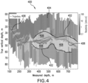
- a resistivity map 400 derived from a reservoir navigation operation for which a geological model has been inverted to match the measured resistivity logs is shown.
- the resulting resistivity map 400 reveals reservoir boundaries 402 between a low-resistive formation 404 (e.g., shale as a caprock) and a highly resistive reservoir 406 (e.g., containing high resistive hydrocarbons).
- the resistivity map 400 can be used to derive a saturation map using standard or advanced saturation equations such as Archie's equation in combination with a porosity distribution map away from the wellbore 408.
- An uncertainty in the position of the reservoir boundaries 402 can add uncertainty in an estimation of hydrocarbon reserves around the wellbore 408.
- Another drilling operation includes a geo-stopping operation for which the interpretation results of the measurements indicate a situation where the continuation of drilling would either be inefficient in terms of later production from or injection into the wellbore or a hazardous situation may be encountered if drilling is continued.
- a fault may be detected by the measurement interpretation so that drilling through the fault may cause the pipe to get stuck in the subsurface.
- Another example is an over-pressurized reservoir compartment which might cause a kick or a blowout if drilling continues into this over-pressurized zone.
- the combined interpretation of hydraulic tests and acoustic and/or resistivity data can be used to reduce uncertainty of the formation and reservoir properties around the wellbore thus enabling improved drilling and/or geosteering.
- prior solutions involved a single, isolated measurement that can be explained by a large number of formation models.
- embodiments provided herein can reduce the amount or number of models which are able to explain all acquired data (e.g., narrowing the potential field of possibilities based on modeling).
- fitting between the model and the measurements can be either conducted automatically using appropriate inversion algorithms or manually by adjusting model parameters (e.g., forward modeling).
- Reservoir navigation or geosteering operations are conducted to optimize high-angle or horizontal (HAHZ) wellbore placement in reservoirs in a way that the well is exposed at a maximum in a hydrocarbon-bearing formation.
- Reservoir navigation is conducted by measuring formation properties such as the electrical resistivity or conductivity around a wellbore and away from the wellbore. The measurements are then used to identify geological boundaries between a reservoir and other structures such as the cap rock above the reservoir, another geological formation below the reservoir, or fluid contacts within a reservoir.
- multiple measurements are conducted with different penetration depths away from the wellbore (e.g., outward from the BHA 202 and/or the drill string 204).
- the measurements obtained downhole by various measurement devices e.g., sensors 200
- each selected to measure one or more specific characteristics of a downhole environment can be transmitted to the surface (e.g., telemetered using communication device 226 to a surface control unit 40).
- Other means and mechanisms for communication between the downhole tools and devices and the surface are contemplated as known by those of skill in the art.
- the data of the multiple measurements are then used to create a geological model around the wellbore (e.g., wellbore 26), which contains a structural and/or architectural component and a petrophysical property component.
- the geological model is composed of petrophysical properties such as the electrical resistivity/conductivity, the acoustic impedance, the bulk density, the porosity, the permeability etc., as obtained by the sensors 200. These properties together with the reservoir architecture can then be used to calculate an expected sensor response by formation evaluation tools. Expected sensor responses can then be compared against measured signals from the formation evaluation tools. In some embodiments, the comparison can be done manually such that the geological model is manually refined until it is able to represent the measured signals (i.e., forward modeling).
- an algorithm can be applied to automatically adjust the geological model unit it is able to represent the measured signals (i.e., inversion modeling).
- inversion modeling One challenge encountered with these models is their non-uniqueness: different models (about the structures/reservoir architecture and petrophysical properties) can explain the same measurement signals, i.e., multiple models can represent a single measured signal.
- constraining the geological model by additional measurements is essential to reduce ambiguities in the geological model.
- Hydraulic tests include producing or injecting fluid from or into a wellbore, ideally at constant flow rates. After production or injection, the well is shut-in and a pressure build-up or drawdown during the shut-in phase is monitored. The recorded pressure response during drawdown or buildup and shut-in phase can then be interpreted using techniques for pressure transients analysis (PTA) such as Horner plots, derivative analyses, log-log plots, etc.
- PTA pressure transients analysis
- the analysis can be conducted analytically or numerically, depending on the complexity of an underlying reservoir model. Hydraulically bounded reservoirs respond different hydraulically compared to reservoirs assumed infinite in extent. As such, an investigation of reservoir architecture is possible with PTA.
- Hydraulic tests can be executed using different configurations of test equipment and/or test procedure(s).
- a test procedure can include conducting a constant-rate injection or production/drawdown test for which fluid is injected into or produced from a subsurface formation at a constant volume over time.
- Another hydraulic test can include a step-wise pump rate test where the injection or production/drawdown rate is kept constant over a pre-defined amount of time but is then step-wise increased or decreased for a pre-defined amount of time.
- Yet another configuration includes an oscillating injection or production/drawdown test for which the injection or production/drawdown rate is oscillated with a certain amplitude and phase. Amplitude and phase may be kept constant or may be variable during the hydraulic test.
- downhole tools can be equipped in a way that allows hydraulic tests to be performed at dedicated or predetermined positions along a well trajectory.
- different equipment configurations can be employed to conduct hydraulic tests.
- formation pressure test devices can attach a pad to a formation wall to inject or produce (drawdown) fluid into/from the formation.
- Control of the injection/production procedure either automatically or by uphole commands allows conducting similar hydraulic tests as the above mentioned well tests but at dedicated or predetermined locations.
- one or more packers can be positioned in a bottom-hole assembly (e.g., BHA 90) to pack-off a portion of the formation and to conduct a dedicated or specific hydraulic test by injecting drilling fluid or other fluid into the packed-off portion of the wellbore using surface pumps or pumps located in or on the bottomhole assembly.
- a bottom-hole assembly e.g., BHA 90
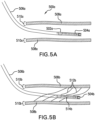
- the configuration of the test equipment and/or the test procedure can be selected based on a desired resolution and/or accuracy to be obtained from the interpretation of the test. For example, deriving structural information from very deep-reading measurements can provide a large uncertainty to the position of structures such as bed boundaries away from the wellbore, as illustrated in FIG. 5A .
- a hydraulic test configuration may be selected with similar resolution capabilities. For example, a system 500a with a packer 502a contained in a bottomhole assembly 504a can be used to conduct a hydraulic test over an elongated section of a wellbore 506a, with the elongation being defined by the distance between the packer 502a and a total depth of the wellbore 506a.
- the interpretation of the hydraulic test can confirm or disconfirm a location of formation boundaries 508a within an uncertainty 510a of the interpretation results obtained from a deep-reading tool.
- an image acquired at or near a wall of the wellbore 506b can reveal detailed structural information in the vicinity of the wellbore 506b, with the position of the structures being small compared to information obtained from deep-reading measurements.
- Structures may be reservoir-internal stratigraphic layering 512b, as illustrated in FIG. 5B .
- a hydraulic test configuration may include a formation pressure tester 514b configured on a bottomhole assembly 504b.
- the formation pressure test 514b can provide localized information of formation boundaries 508b (having uncertainty 510b) around the wellbore 506b and also reveal if stratigraphic layering 512b serves as a hydraulic boundary which would not be detectable by a test configuration as described by FIG. 5A .
- embodiments provided herein include drilling a wellbore into an earth formation, conducting one or more measurements to evaluate a surrounding of the wellbore, creating a model of the surrounding of the wellbore (e.g., formation), using the model to evaluate a hydraulic behavior of the formation, conducting a hydraulic test using a formation testing and sampling tool, comparing the hydraulic response of the formation model with the hydraulic test, updating the formation model until the measurement and hydraulic test results coincide, and making a reservoir navigation decision.
- Measurements to evaluate the surrounding formation include, but are not limited to, resistivity, seismic, acoustic, electromagnetic measurements, either azimuthal or circumferential, etc.
- the created model can be either analytical or numerical, so that the evaluation of the hydraulic behavior of the reservoir can be conducted either by analytical means or numerical simulation.
- the update of the formation model is either conducted manually by adjusting either properties of the formation or the architecture of the formation (referred to as forward modeling) or by a mathematical operation (referred to as inversion modeling).
- Different hydraulic tests may be conducted, and the downhole tool may be configured to conduct a test which seems most promising for a specific structural model around the wellbore.
- a hydraulic test can be conducted using a constant injection/production rate.
- the injection/production rate can be conducted at multiple different and/or variable rates.
- an oscillating and/injection/production pattern can be applied to the hydraulic test.
- a downlink may be sent to the tool to select the test procedure. Accordingly, advantageously, a combination of hydraulic and formation evaluation measurements are used to constrain a geological model around the wellbore and thus provide an improved and accurate estimation of the formation and thus enabled improved drilling operations.
- FIG. 3 is a flow process of a method for optimizing modeling for drilling operations in a wellbore penetrating the earth with a drill string.
- Block 302 calls for measuring a first formation characteristic.
- the first formation characteristic include electrical resistivity/conductivity, acoustic impedance, bulk density, porosity, and/or permeability.
- the sensor is disposed in a bottomhole assembly of the drill string.
- first formation characteristic is transmitted to a surface device, such as a computing device.
- the sensor represents a plurality of sensors that may be in one location or a plurality of locations distributed along the drill string.
- the first formation characteristic can comprise multiple formation characteristics and can be obtained from a plurality of different sensors.
- Block 304 calls for generating a model representative of the formation.
- the model is based on the measured first formation characteristic(s).
- the modeling performed at block 304 may be performed as known in the art.
- data measured related to the first characteristic can be transmitted to a computing device at the surface and processed to generate one or more models that represent the data of the first characteristic for a downhole formation.
- the computing device can be connected to a data base and/or memory to store the representative model in the context of a larger Earth model containing an entire hydrocarbon reservoir or even an entire field with multiple hydrocarbon reservoirs.
- the integration may lead to a refinement of the initial formation model in the context of the Earth model.
- Block 306 calls for measuring a second formation characteristic.
- the second formation characteristic is different from the first formation characteristic.
- the second formation characteristic is a hydraulic characteristic of the formation surrounding the wellbore.
- a hydraulic testing tool is disposed in a bottombole assembly (e.g., BHA 90) of the drill string (e.g., drill string 20).
- second formation characteristic is transmitted to a surface device, such as a computing device.
- hydraulic testing tool represents a plurality of testing tools that may be in one location or a plurality of locations distributed along the drill string.
- one pressure pump to inject or produce fluid can be located in a bottomhole assembly and multiple pressure sensors can be distributed along the drill string or bottomhole assembly to monitor a pressure propagation within a formation.
- a tool can be positioned within the bottomhole assembly and/or in the drill string and moved to various different positions so that a series of hydraulic tests can be conducted along the wellbore.
- the second formation characteristic can comprise multiple formation characteristics and can be obtained from a plurality of different testing tools (or sensors).
- the second formation characteristic (and/or the tools to measure such formation characteristic) can be selected based on information related to the first formation characteristic and/or the model generated at Block 304
- Block 308 calls for updating the model of Block 304 to include information obtained at Block 306 (e.g., the second formation characteristic).
- the update of the formation model is either conducted manually by adjusting either properties of the formation or the architecture of the formation (referred to as forward modeling) or by a mathematical operation (referred to as inversion modeling).
- the update of the model is performed at or on the computing device on the surface.
- the update may be performed on a single, prior model that is adjusted to match the information obtained from the measurement of the second formation characteristic.
- the information of the second formation characteristic can be used to eliminate various models from a group of prior generated models (e.g., models generated at Block 304), thus narrowing the number of possible models.
- Block 310 calls for performing a drilling operation based on the updated model. That is, based on the refined model(s), a drilling operation can be performed that is most efficient based on the improved modeling achieved by the above described process.
- the drilling operation can include geosteering, direction, drilling speed, drilling mud, and/or other aspects of drilling such that optimized and efficient drilling and/or subsequent production or injection from or into the wellbore can be performed.
- Block 310 can include transmitting selected drilling parameters selected, in view of the modified model, to a drill string controller configured to control the drill string in accordance with the selected drilling parameters
- the method in FIG. 3 may also include drilling the wellbore with a drilling rig using the selected models in order to improve drilling operations
- the method may also include controlling one or more drilling parameters using a feedback controller that receives input from a drilling parameter sensor in accordance with a signal received from a processor that selected the drilling parameters that are in accordance with the modified model(s).
- various embodiments provided herein may provide improved and/or efficient completion processes for horizontal wells.
- Various embodiments can maximize and/or otherwise optimize the location of perforation clusters for completion processes by ensuring locating the perforation cluster at ideal locations for perforation and fracturing.
- various analysis components may be used including a digital and/or an analog system.
- controllers, computer processing systems, and/or geo-steering systems as provided herein and/or used with embodiments described herein may include digital and/or analog systems.
- the systems may have components such as processors, storage media, memory, inputs, outputs, communications links (e.g., wired, wireless, optical, or other), user interfaces, software programs, signal processors (e.g., digital or analog) and other such components (e.g., such as resistors, capacitors, inductors, and others) to provide for operation and analyses of the apparatus and methods disclosed herein in any of several manners well-appreciated in the art.
- teachings may be, but need not be, implemented in conjunction with a set of computer executable instructions stored on a non-transitory computer readable medium, including memory (e.g., ROMs, RAMs), optical (e.g., CD-ROMs), or magnetic (e.g., disks, hard drives), or any other type that when executed causes a computer to implement the methods and/or processes described herein.
- ROMs read-only memory
- RAMs random access memory
- optical e.g., CD-ROMs
- magnetic e.g., disks, hard drives
- Processed data such as a result of an implemented method, may be transmitted as a signal via a processor output interface to a signal receiving device.
- the signal receiving device may be a display monitor or printer for presenting the result to a user.
- the signal receiving device may be memory or a storage medium. It will be appreciated that storing the result in memory or the storage medium may transform the memory or storage medium into a new state (i.e., containing the result) from a prior state (i.e., not containing the result). Further, in some embodiments, an alert signal may be transmitted from the processor to a user interface if the result exceeds a threshold value.
- a sensor, transmitter, receiver, transceiver, antenna, controller, optical unit, electrical unit, and/or electromechanical unit may be included in support of the various aspects discussed herein or in support of other functions beyond this disclosure.
- the teachings of the present disclosure may be used in a variety of well operations. These operations may involve using one or more treatment agents to treat a formation, the fluids resident in a formation, a wellbore, and / or equipment in the wellbore, such as production tubing.
- the treatment agents may be in the form of liquids, gases, solids, semi-solids, and mixtures thereof.
- Illustrative treatment agents include, but are not limited to, fracturing fluids, acids, steam, water, brine, anti-corrosion agents, cement, permeability modifiers, drilling muds, emulsifiers, demulsifiers, tracers, flow improvers etc.
- Illustrative well operations include, but are not limited to, hydraulic fracturing, stimulation, tracer injection, cleaning, acidizing, steam injection, water flooding, cementing, etc.
Landscapes
- Engineering & Computer Science (AREA)
- Life Sciences & Earth Sciences (AREA)
- Geology (AREA)
- Mining & Mineral Resources (AREA)
- Physics & Mathematics (AREA)
- Environmental & Geological Engineering (AREA)
- Fluid Mechanics (AREA)
- General Life Sciences & Earth Sciences (AREA)
- Geochemistry & Mineralogy (AREA)
- Chemical & Material Sciences (AREA)
- Analytical Chemistry (AREA)
- Geophysics And Detection Of Objects (AREA)
- Geophysics (AREA)
- Earth Drilling (AREA)
- Investigation Of Foundation Soil And Reinforcement Of Foundation Soil By Compacting Or Drainage (AREA)
- Remote Sensing (AREA)
- Acoustics & Sound (AREA)
- Evolutionary Computation (AREA)
- Health & Medical Sciences (AREA)
- Artificial Intelligence (AREA)
- Computer Vision & Pattern Recognition (AREA)
- Soil Sciences (AREA)
- Medical Informatics (AREA)
- Software Systems (AREA)
- General Physics & Mathematics (AREA)
- Automation & Control Theory (AREA)
- Measurement Of The Respiration, Hearing Ability, Form, And Blood Characteristics Of Living Organisms (AREA)
- Electrical Discharge Machining, Electrochemical Machining, And Combined Machining (AREA)
- Testing Or Calibration Of Command Recording Devices (AREA)
Claims (13)
- Procédé permettant de réaliser une opération de sondage dans un puits de forage (26, 408, 506a, 506b) à l'aide d'un train de tiges (20, 204), le procédé comprenant :la mesure d'au moins une première caractéristique de formation avec au moins un capteur (200) ;la génération d'un modèle pour représenter une formation autour du puits de forage (26, 408, 506a, 506b) en fonction de l'au moins une première caractéristique de formation mesurée ;la mesure d'au moins une seconde caractéristique de formation au moyen d'un essai hydraulique, dans lequel l'essai hydraulique comprenant au moins l'un parmi la production de fluide à partir de ou l'injection d'un fluide dans le puits de forage, l'au moins une seconde caractéristique de formation étant différente de l'au moins une première caractéristique de formation ;la mise à jour automatique du modèle en fonction de l'au moins une seconde caractéristique de formation mesurée ; etla réalisation d'une opération de sondage en fonction du modèle mis à jour ;dans lequel l'essai hydraulique est mené à l'aide d'un outil d'essai hydraulique, dans lequel une configuration de l'outil d'essai hydraulique est choisie en fonction d'informations apparentées à au moins l'un parmi l'au moins une première caractéristique de formation ou le modèle ;dans lequel le train de tiges a un ensemble de fond de trou (202), et l'outil d'essai hydraulique est configuré sur l'ensemble de fond de trou (202, 504b).
- Procédé selon la revendication 1, dans lequel l'opération de sondage est au moins l'une parmi une opération de géo-direction, opération de géo-arrêt, ou une opération de sécurité.
- Procédé selon l'une quelconque des revendications précédentes, dans lequel au moins un capteur (200) est disposé dans ou sur l'ensemble de fond de trou (202).
- Procédé selon l'une quelconque des revendications précédentes, dans lequel des données de capteur (220) provenant de l'au moins un capteur (200) sont analysées par un dispositif informatique (222) comporté dans l'ensemble de fond de trou (202, 504b).
- Procédé selon l'une quelconque des revendications précédentes, dans lequel l'au moins une première caractéristique de formation comprend au moins l'une parmi une résistivité/conductivité électrique, une impédance acoustique, une densité apparente, une porosité, ou une perméabilité.
- Procédé selon l'une quelconque des revendications précédentes, dans lequel l'au moins une seconde caractéristique de formation est une limite de formation (508b).
- Procédé selon l'une quelconque des revendications précédentes, dans lequel l'essai hydraulique comprend le fait de mener une analyse des transitoires de pression.
- Procédé selon l'une quelconque des revendications précédentes, dans lequel l'au moins une seconde caractéristique de formation est choisie en fonction d'informations apparentées à au moins l'un parmi l'au moins une première caractéristique de formation ou le modèle.
- Système permettant de réaliser une opération de sondage dans un puits de forage (26, 408, 506a, 506b) à l'aide d'un train de tiges (20, 204), le système comprenant :un support configuré pour être transporté à travers un puits de forage (26, 408, 506a, 506b) et supporter un trépan (50) sur celui-ci ;au moins un capteur (200) configuré pour obtenir des informations apparentées à une première caractéristique de formation ;un outil d'essai hydraulique configuré pour obtenir des informations apparentées à une seconde caractéristique de formation au moyen d'un essai hydraulique, dans lequel l'outil d'essai hydraulique est configuré pour au moins l'un parmi le fait d'injecter du fluide dans ou de produire du fluide à partir du puits de forage ; et un processeur configuré pour optimiser une opération de sondage, le système étant configuré pour : mesurer une première caractéristique de formation avec l'au moins un capteur (200) ;générer un modèle pour représenter une formation autour du puits de forage (26, 408, 506a, 506b) en fonction de la première caractéristique de formation mesurée ;mesurer une seconde caractéristique de formation au moyen de l'essai hydraulique, la seconde caractéristique de formation étant différente de la première caractéristique de formation ;mettre à jour automatiquement le modèle en fonction de la seconde caractéristique de formation mesurée ; etréaliser une opération de sondage avec le trépan (50) en fonction du modèle mis à jour ; dans lequel une configuration de l'outil d'essai hydraulique est choisie en fonction d'informations apparentées à au moins l'un parmi la première caractéristique de formation ou le modèle ;dans lequel le train de tiges a un ensemble de fond de trou (202), et l'outil d'essai hydraulique est configuré sur l'ensemble de fond de trou (202, 504b).
- Système selon la revendication 9, dans lequel la seconde caractéristique de formation comprend une limite de formation (508b).
- Système selon la revendication 9 ou 10, dans lequel l'au moins un capteur (200) est configuré sur l'ensemble de fond de trou.
- Système selon l'une quelconque des revendications 9 à 11, dans lequel la première caractéristique de formation comprend au moins l'une parmi une résistivité/conductivité électrique, une impédance acoustique, une densité apparente, une porosité, ou une perméabilité.
- Système selon l'une quelconque des revendications 9 à 12, dans lequel l'essai hydraulique comprend le fait de mener une analyse des transitoires de pression.
Applications Claiming Priority (2)
| Application Number | Priority Date | Filing Date | Title |
|---|---|---|---|
| US15/151,644 US11454102B2 (en) | 2016-05-11 | 2016-05-11 | Methods and systems for optimizing a drilling operation based on multiple formation measurements |
| PCT/US2017/031526 WO2017196714A1 (fr) | 2016-05-11 | 2017-05-08 | Procédés et systèmes pour optimiser une opération de forage en fonction de multiples mesures de formation |
Publications (3)
| Publication Number | Publication Date |
|---|---|
| EP3455457A1 EP3455457A1 (fr) | 2019-03-20 |
| EP3455457A4 EP3455457A4 (fr) | 2020-01-22 |
| EP3455457B1 true EP3455457B1 (fr) | 2024-09-04 |
Family
ID=60267893
Family Applications (1)
| Application Number | Title | Priority Date | Filing Date |
|---|---|---|---|
| EP17796621.5A Active EP3455457B1 (fr) | 2016-05-11 | 2017-05-08 | Procédés et systèmes pour optimiser une opération de forage en fonction de multiples mesures de formation |
Country Status (4)
| Country | Link |
|---|---|
| US (1) | US11454102B2 (fr) |
| EP (1) | EP3455457B1 (fr) |
| SA (1) | SA518400405B1 (fr) |
| WO (1) | WO2017196714A1 (fr) |
Families Citing this family (5)
| Publication number | Priority date | Publication date | Assignee | Title |
|---|---|---|---|---|
| US10738548B2 (en) * | 2016-01-29 | 2020-08-11 | Halliburton Energy Services, Inc. | Stochastic control method for mud circulation system |
| GB2568205B (en) * | 2016-10-19 | 2021-08-11 | Halliburton Energy Services Inc | Avoiding geological formation boundaries during drilling operations |
| WO2019005045A1 (fr) * | 2017-06-28 | 2019-01-03 | Halliburton Energy Services, Inc. | Manipulation interactive à réalité virtuelle de données de fond de trou |
| CN111648757A (zh) * | 2020-04-26 | 2020-09-11 | 中国石油集团渤海钻探工程有限公司 | 一种双摆提速钻具工作特性地面测试系统 |
| US12560075B2 (en) * | 2023-06-12 | 2026-02-24 | Halliburton Energy Services, Inc. | Gradational resistivity models with local anisotropy for distance to bed boundary inversion |
Family Cites Families (52)
| Publication number | Priority date | Publication date | Assignee | Title |
|---|---|---|---|---|
| US6754588B2 (en) * | 1999-01-29 | 2004-06-22 | Platte River Associates, Inc. | Method of predicting three-dimensional stratigraphy using inverse optimization techniques |
| US6246963B1 (en) * | 1999-01-29 | 2001-06-12 | Timothy A. Cross | Method for predicting stratigraphy |
| US6671623B1 (en) | 1999-10-15 | 2003-12-30 | Schlumberger Technology Corporation | Methods and system for characterizing the response of subsurface measurements to determine wellbore and formation characteristics |
| US6393363B1 (en) | 2000-06-28 | 2002-05-21 | Schlumberger Technology Corporation | Method and apparatus for the measurement of the electrical resistivity of geologic formations employing modeling data |
| US6686736B2 (en) * | 2000-08-30 | 2004-02-03 | Baker Hughes Incorporated | Combined characterization and inversion of reservoir parameters from nuclear, NMR and resistivity measurements |
| US6541975B2 (en) | 2001-08-23 | 2003-04-01 | Kjt Enterprises, Inc. | Integrated borehole system for reservoir detection and monitoring |
| US6968909B2 (en) * | 2002-03-06 | 2005-11-29 | Schlumberger Technology Corporation | Realtime control of a drilling system using the output from combination of an earth model and a drilling process model |
| US7523024B2 (en) * | 2002-05-17 | 2009-04-21 | Schlumberger Technology Corporation | Modeling geologic objects in faulted formations |
| US6903553B2 (en) | 2002-09-06 | 2005-06-07 | Baker Hughes Incorporated | Method and apparatus for a quadrupole transmitter for directionally sensitive induction tool |
| FR2846996B1 (fr) | 2002-11-08 | 2004-12-24 | Schlumberger Services Petrol | Procede et dispositif de determination de la resistivite dans une formation geologique traversee par un puits tube |
| US7063174B2 (en) | 2002-11-12 | 2006-06-20 | Baker Hughes Incorporated | Method for reservoir navigation using formation pressure testing measurement while drilling |
| US7046009B2 (en) | 2003-12-24 | 2006-05-16 | Baker Hughes Incorporated | Method for measuring transient electromagnetic components to perform deep geosteering while drilling |
| US7054751B2 (en) * | 2004-03-29 | 2006-05-30 | Halliburton Energy Services, Inc. | Methods and apparatus for estimating physical parameters of reservoirs using pressure transient fracture injection/falloff test analysis |
| US7141981B2 (en) | 2004-07-23 | 2006-11-28 | Baker Hughes Incorporated | Error correction and calibration of a deep reading propagation resistivity tool |
| US7778811B2 (en) * | 2004-11-12 | 2010-08-17 | Baker Hughes Incorporated | Method and system for predictive stratigraphy images |
| US7483793B2 (en) | 2005-07-27 | 2009-01-27 | Baker Hughes Incorporated | Method of generating a deep resistivity image in LWD measurements |
| AU2007277410B2 (en) | 2006-07-25 | 2012-02-16 | Exxonmobil Upstream Research Company | Method for determining physical properties of structures |
| AU2007295028B2 (en) * | 2006-09-13 | 2011-12-15 | Exxonmobil Upstream Research Company | Rapid inversion of electromagnetic reconnaissance survey data |
| US9135475B2 (en) * | 2007-01-29 | 2015-09-15 | Sclumberger Technology Corporation | System and method for performing downhole stimulation operations |
| BRPI0711465B1 (pt) | 2007-03-16 | 2018-04-24 | Halliburton Energy Services, Inc. | ferramenta de perfilagem, e, método para ferramenta de perfilagem de resistividade azimutalmente sensível |
| US7751280B2 (en) * | 2007-03-27 | 2010-07-06 | Schlumberger Technology Corporation | Determining wellbore position within subsurface earth structures and updating models of such structures using azimuthal formation measurements |
| US20080236842A1 (en) * | 2007-03-27 | 2008-10-02 | Schlumberger Technology Corporation | Downhole oilfield apparatus comprising a diamond-like carbon coating and methods of use |
| EP2165218B1 (fr) | 2007-06-15 | 2017-02-22 | Baker Hughes Incorporated | Imagerie d'une structure de formation devant le trépan |
| US7723991B2 (en) | 2007-10-02 | 2010-05-25 | Baker Hughes Incorporated | Apparatus and method for azimuthal MWD resistivity imaging at multiple depths of investigation |
| US7912648B2 (en) | 2007-10-02 | 2011-03-22 | Baker Hughes Incorporated | Method and apparatus for imaging bed boundaries using azimuthal propagation resistivity measurements |
| US8489375B2 (en) | 2007-10-22 | 2013-07-16 | Schlumberger Technology Corporation | Formation modeling while drilling for enhanced high angle for horizontal well placement |
| US8364404B2 (en) | 2008-02-06 | 2013-01-29 | Schlumberger Technology Corporation | System and method for displaying data associated with subsurface reservoirs |
| US8008919B2 (en) | 2008-03-25 | 2011-08-30 | Baker Hughes Incorporated | Method for compensating drill pipe and near-borehole effect on and electronic noise in transient resistivity measurements |
| US8527248B2 (en) | 2008-04-18 | 2013-09-03 | Westerngeco L.L.C. | System and method for performing an adaptive drilling operation |
| US7966166B2 (en) | 2008-04-18 | 2011-06-21 | Schlumberger Technology Corp. | Method for determining a set of net present values to influence the drilling of a wellbore and increase production |
| US8239172B2 (en) | 2008-11-17 | 2012-08-07 | Baker Hughes Incorporated | Method of deep resistivity transient measurement while drilling |
| WO2010080366A1 (fr) * | 2009-01-09 | 2010-07-15 | Exxonmobil Upstream Research Company | Détection d'hydrocarbure au moyen de données sismiques passives |
| NO338750B1 (no) * | 2009-03-02 | 2016-10-17 | Drilltronics Rig Systems As | Fremgangsmåte og system for automatisert styring av boreprosess |
| AU2010310816B2 (en) | 2009-10-20 | 2016-01-28 | Schlumberger Technology B.V. | Methods for characterization of formations, navigating drill paths, and placing wells in earth boreholes |
| US8729903B2 (en) * | 2009-11-09 | 2014-05-20 | Exxonmobil Upstream Research Company | Method for remote identification and characterization of hydrocarbon source rocks using seismic and electromagnetic geophysical data |
| US8818779B2 (en) | 2009-12-21 | 2014-08-26 | Baker Hughes Incorporated | System and methods for real-time wellbore stability service |
| US8731889B2 (en) * | 2010-03-05 | 2014-05-20 | Schlumberger Technology Corporation | Modeling hydraulic fracturing induced fracture networks as a dual porosity system |
| US8756018B2 (en) | 2010-06-23 | 2014-06-17 | Schlumberger Technology Corporation | Method for time lapsed reservoir monitoring using azimuthally sensitive resistivity measurements while drilling |
| CA2811631C (fr) | 2010-09-17 | 2015-09-08 | Baker Hughes Incorporated | Navigation dans un reservoir au moyen d'un champ magnetique de courants continus |
| MX336561B (es) * | 2010-12-30 | 2016-01-25 | Schlumberger Technology Bv | Sistema y metodo para realizar operaciones de estimulacion en el fondo del pozo. |
| BR112013023019A2 (pt) * | 2011-03-09 | 2016-12-13 | Prad Res & Dev Ltd | método para caracterizar uma formação subterrânea utilizando uma resposta de pressão de fluido durante operações de perfuração de poços, e método para calcular vazão de fluido fluindo de um poço, baseado em uma resposta da pressão de fluido durante operações de perfuração de poço |
| EP2697669B1 (fr) | 2011-04-18 | 2018-07-11 | Halliburton Energy Services, Inc. | Procédé de traitement de fond de puits en temps réel et détection de limite de couche pour application de géoguidage |
| US8899349B2 (en) * | 2011-07-22 | 2014-12-02 | Schlumberger Technology Corporation | Methods for determining formation strength of a wellbore |
| US8862405B2 (en) * | 2011-12-06 | 2014-10-14 | Schlumberger Technology Corporation | System and method for producing look-ahead profile measurements in a drilling operation |
| US10429537B2 (en) | 2012-01-30 | 2019-10-01 | Schlumberger Technology Corporation | Efficiency of pixel-based inversion algorithms |
| EP2815070B1 (fr) * | 2012-02-17 | 2016-08-24 | Services Pétroliers Schlumberger | Étalonnage basé sur une inversion d'outils électromagnétiques en fond de trou |
| WO2013165711A1 (fr) * | 2012-05-04 | 2013-11-07 | Exxonmobil Upstream Research Company | Systèmes et procédés de détection d'une intersection entre un puits de forage et une structure souterraine qui comprend un matériau de marqueur |
| EP2809878A4 (fr) | 2012-05-25 | 2015-11-11 | Halliburton Energy Services Inc | Commande d'opération de forage à l'aide de multiples modèles hydrauliques simultanés |
| EP2841692B1 (fr) | 2013-07-18 | 2018-07-11 | Halliburton Energy Services, Inc. | Détection d'emplacement de limite de plusieurs couches placées sous la surface |
| US10324230B2 (en) * | 2014-10-28 | 2019-06-18 | Schlumberger Technology Corporation | Integrated interpretation of pressure and rate transients for production forecasting |
| US10385686B2 (en) * | 2014-10-28 | 2019-08-20 | Eog Resources, Inc. | Completions index analysis |
| US10197704B2 (en) * | 2014-12-19 | 2019-02-05 | Baker Hughes, A Ge Company, Llc | Corrective scaling of interpreted fractures based on the microseismic detection range bias correction |
-
2016
- 2016-05-11 US US15/151,644 patent/US11454102B2/en active Active
-
2017
- 2017-05-08 EP EP17796621.5A patent/EP3455457B1/fr active Active
- 2017-05-08 WO PCT/US2017/031526 patent/WO2017196714A1/fr not_active Ceased
-
2018
- 2018-11-08 SA SA518400405A patent/SA518400405B1/ar unknown
Also Published As
| Publication number | Publication date |
|---|---|
| WO2017196714A1 (fr) | 2017-11-16 |
| EP3455457A1 (fr) | 2019-03-20 |
| US11454102B2 (en) | 2022-09-27 |
| EP3455457A4 (fr) | 2020-01-22 |
| US20170328191A1 (en) | 2017-11-16 |
| BR112018073123A2 (pt) | 2019-03-06 |
| SA518400405B1 (ar) | 2024-07-21 |
Similar Documents
| Publication | Publication Date | Title |
|---|---|---|
| US11492900B2 (en) | Gas ratio volumetrics for reservoir navigation | |
| US11378506B2 (en) | Methods and systems for monitoring drilling fluid rheological characteristics | |
| US11867051B2 (en) | Incremental downhole depth methods and systems | |
| EP3436660B1 (fr) | Analyse modale d'opération de fond de trou | |
| US10590760B2 (en) | Real-time monitoring of downhole dynamic events | |
| US10480311B2 (en) | Downhole intervention operation optimization | |
| EP3455457B1 (fr) | Procédés et systèmes pour optimiser une opération de forage en fonction de multiples mesures de formation | |
| US11966002B2 (en) | Systems and methods for downhole determination of drilling characteristics | |
| US10746016B2 (en) | Time division multiplexing of distributed downhole sensing systems | |
| US10443351B2 (en) | Backflow prevention assembly for downhole operations | |
| EP3464817B1 (fr) | Système et procédé pour la détermination du retard de propagation sur une ligne de communication | |
| US11828166B2 (en) | Active magnetic ranging by wellhead current injection | |
| EP3695097B1 (fr) | Analyse à niveau de champ de journaux d'opérations de fond de trou | |
| US20200049003A1 (en) | Systems and methods for evaluating reservoir supercharged conditions | |
| US12326389B2 (en) | Combined processing of borehole imagers and dielectric tools | |
| BR112018073123B1 (pt) | Método e sistema para realizar uma operação de perfuração em um poço de exploração usando uma coluna de perfuração |
Legal Events
| Date | Code | Title | Description |
|---|---|---|---|
| STAA | Information on the status of an ep patent application or granted ep patent |
Free format text: STATUS: THE INTERNATIONAL PUBLICATION HAS BEEN MADE |
|
| PUAI | Public reference made under article 153(3) epc to a published international application that has entered the european phase |
Free format text: ORIGINAL CODE: 0009012 |
|
| STAA | Information on the status of an ep patent application or granted ep patent |
Free format text: STATUS: REQUEST FOR EXAMINATION WAS MADE |
|
| 17P | Request for examination filed |
Effective date: 20181207 |
|
| AK | Designated contracting states |
Kind code of ref document: A1 Designated state(s): AL AT BE BG CH CY CZ DE DK EE ES FI FR GB GR HR HU IE IS IT LI LT LU LV MC MK MT NL NO PL PT RO RS SE SI SK SM TR |
|
| AX | Request for extension of the european patent |
Extension state: BA ME |
|
| DAV | Request for validation of the european patent (deleted) | ||
| DAX | Request for extension of the european patent (deleted) | ||
| A4 | Supplementary search report drawn up and despatched |
Effective date: 20200107 |
|
| RIC1 | Information provided on ipc code assigned before grant |
Ipc: E21B 47/00 20120101ALI20191219BHEP Ipc: E21B 49/00 20060101ALI20191219BHEP Ipc: E21B 44/00 20060101AFI20191219BHEP |
|
| STAA | Information on the status of an ep patent application or granted ep patent |
Free format text: STATUS: EXAMINATION IS IN PROGRESS |
|
| 17Q | First examination report despatched |
Effective date: 20220407 |
|
| P01 | Opt-out of the competence of the unified patent court (upc) registered |
Effective date: 20230526 |
|
| GRAP | Despatch of communication of intention to grant a patent |
Free format text: ORIGINAL CODE: EPIDOSNIGR1 |
|
| STAA | Information on the status of an ep patent application or granted ep patent |
Free format text: STATUS: GRANT OF PATENT IS INTENDED |
|
| INTG | Intention to grant announced |
Effective date: 20240314 |
|
| GRAS | Grant fee paid |
Free format text: ORIGINAL CODE: EPIDOSNIGR3 |
|
| RAP3 | Party data changed (applicant data changed or rights of an application transferred) |
Owner name: BAKER HUGHES HOLDINGS LLC |
|
| GRAA | (expected) grant |
Free format text: ORIGINAL CODE: 0009210 |
|
| STAA | Information on the status of an ep patent application or granted ep patent |
Free format text: STATUS: THE PATENT HAS BEEN GRANTED |
|
| AK | Designated contracting states |
Kind code of ref document: B1 Designated state(s): AL AT BE BG CH CY CZ DE DK EE ES FI FR GB GR HR HU IE IS IT LI LT LU LV MC MK MT NL NO PL PT RO RS SE SI SK SM TR |
|
| REG | Reference to a national code |
Ref country code: GB Ref legal event code: FG4D |
|
| REG | Reference to a national code |
Ref country code: CH Ref legal event code: EP |
|
| REG | Reference to a national code |
Ref country code: IE Ref legal event code: FG4D |
|
| REG | Reference to a national code |
Ref country code: DE Ref legal event code: R096 Ref document number: 602017084663 Country of ref document: DE |
|
| REG | Reference to a national code |
Ref country code: LT Ref legal event code: MG9D |
|
| REG | Reference to a national code |
Ref country code: NL Ref legal event code: MP Effective date: 20240904 |
|
| PG25 | Lapsed in a contracting state [announced via postgrant information from national office to epo] |
Ref country code: PL Free format text: LAPSE BECAUSE OF FAILURE TO SUBMIT A TRANSLATION OF THE DESCRIPTION OR TO PAY THE FEE WITHIN THE PRESCRIBED TIME-LIMIT Effective date: 20240904 Ref country code: GR Free format text: LAPSE BECAUSE OF FAILURE TO SUBMIT A TRANSLATION OF THE DESCRIPTION OR TO PAY THE FEE WITHIN THE PRESCRIBED TIME-LIMIT Effective date: 20241205 Ref country code: FI Free format text: LAPSE BECAUSE OF FAILURE TO SUBMIT A TRANSLATION OF THE DESCRIPTION OR TO PAY THE FEE WITHIN THE PRESCRIBED TIME-LIMIT Effective date: 20240904 |
|
| PG25 | Lapsed in a contracting state [announced via postgrant information from national office to epo] |
Ref country code: BG Free format text: LAPSE BECAUSE OF FAILURE TO SUBMIT A TRANSLATION OF THE DESCRIPTION OR TO PAY THE FEE WITHIN THE PRESCRIBED TIME-LIMIT Effective date: 20240904 |
|
| PG25 | Lapsed in a contracting state [announced via postgrant information from national office to epo] |
Ref country code: LV Free format text: LAPSE BECAUSE OF FAILURE TO SUBMIT A TRANSLATION OF THE DESCRIPTION OR TO PAY THE FEE WITHIN THE PRESCRIBED TIME-LIMIT Effective date: 20240904 |
|
| PG25 | Lapsed in a contracting state [announced via postgrant information from national office to epo] |
Ref country code: HR Free format text: LAPSE BECAUSE OF FAILURE TO SUBMIT A TRANSLATION OF THE DESCRIPTION OR TO PAY THE FEE WITHIN THE PRESCRIBED TIME-LIMIT Effective date: 20240904 |
|
| PG25 | Lapsed in a contracting state [announced via postgrant information from national office to epo] |
Ref country code: ES Free format text: LAPSE BECAUSE OF FAILURE TO SUBMIT A TRANSLATION OF THE DESCRIPTION OR TO PAY THE FEE WITHIN THE PRESCRIBED TIME-LIMIT Effective date: 20240904 Ref country code: RS Free format text: LAPSE BECAUSE OF FAILURE TO SUBMIT A TRANSLATION OF THE DESCRIPTION OR TO PAY THE FEE WITHIN THE PRESCRIBED TIME-LIMIT Effective date: 20241204 |
|
| PG25 | Lapsed in a contracting state [announced via postgrant information from national office to epo] |
Ref country code: RS Free format text: LAPSE BECAUSE OF FAILURE TO SUBMIT A TRANSLATION OF THE DESCRIPTION OR TO PAY THE FEE WITHIN THE PRESCRIBED TIME-LIMIT Effective date: 20241204 Ref country code: PL Free format text: LAPSE BECAUSE OF FAILURE TO SUBMIT A TRANSLATION OF THE DESCRIPTION OR TO PAY THE FEE WITHIN THE PRESCRIBED TIME-LIMIT Effective date: 20240904 Ref country code: LV Free format text: LAPSE BECAUSE OF FAILURE TO SUBMIT A TRANSLATION OF THE DESCRIPTION OR TO PAY THE FEE WITHIN THE PRESCRIBED TIME-LIMIT Effective date: 20240904 Ref country code: HR Free format text: LAPSE BECAUSE OF FAILURE TO SUBMIT A TRANSLATION OF THE DESCRIPTION OR TO PAY THE FEE WITHIN THE PRESCRIBED TIME-LIMIT Effective date: 20240904 Ref country code: GR Free format text: LAPSE BECAUSE OF FAILURE TO SUBMIT A TRANSLATION OF THE DESCRIPTION OR TO PAY THE FEE WITHIN THE PRESCRIBED TIME-LIMIT Effective date: 20241205 Ref country code: FI Free format text: LAPSE BECAUSE OF FAILURE TO SUBMIT A TRANSLATION OF THE DESCRIPTION OR TO PAY THE FEE WITHIN THE PRESCRIBED TIME-LIMIT Effective date: 20240904 Ref country code: ES Free format text: LAPSE BECAUSE OF FAILURE TO SUBMIT A TRANSLATION OF THE DESCRIPTION OR TO PAY THE FEE WITHIN THE PRESCRIBED TIME-LIMIT Effective date: 20240904 Ref country code: BG Free format text: LAPSE BECAUSE OF FAILURE TO SUBMIT A TRANSLATION OF THE DESCRIPTION OR TO PAY THE FEE WITHIN THE PRESCRIBED TIME-LIMIT Effective date: 20240904 |
|
| REG | Reference to a national code |
Ref country code: AT Ref legal event code: MK05 Ref document number: 1720593 Country of ref document: AT Kind code of ref document: T Effective date: 20240904 |
|
| PG25 | Lapsed in a contracting state [announced via postgrant information from national office to epo] |
Ref country code: NL Free format text: LAPSE BECAUSE OF FAILURE TO SUBMIT A TRANSLATION OF THE DESCRIPTION OR TO PAY THE FEE WITHIN THE PRESCRIBED TIME-LIMIT Effective date: 20240904 |
|
| PG25 | Lapsed in a contracting state [announced via postgrant information from national office to epo] |
Ref country code: PT Free format text: LAPSE BECAUSE OF FAILURE TO SUBMIT A TRANSLATION OF THE DESCRIPTION OR TO PAY THE FEE WITHIN THE PRESCRIBED TIME-LIMIT Effective date: 20250106 Ref country code: IS Free format text: LAPSE BECAUSE OF FAILURE TO SUBMIT A TRANSLATION OF THE DESCRIPTION OR TO PAY THE FEE WITHIN THE PRESCRIBED TIME-LIMIT Effective date: 20250104 |
|
| PG25 | Lapsed in a contracting state [announced via postgrant information from national office to epo] |
Ref country code: SM Free format text: LAPSE BECAUSE OF FAILURE TO SUBMIT A TRANSLATION OF THE DESCRIPTION OR TO PAY THE FEE WITHIN THE PRESCRIBED TIME-LIMIT Effective date: 20240904 Ref country code: RO Free format text: LAPSE BECAUSE OF FAILURE TO SUBMIT A TRANSLATION OF THE DESCRIPTION OR TO PAY THE FEE WITHIN THE PRESCRIBED TIME-LIMIT Effective date: 20240904 |
|
| PG25 | Lapsed in a contracting state [announced via postgrant information from national office to epo] |
Ref country code: EE Free format text: LAPSE BECAUSE OF FAILURE TO SUBMIT A TRANSLATION OF THE DESCRIPTION OR TO PAY THE FEE WITHIN THE PRESCRIBED TIME-LIMIT Effective date: 20240904 Ref country code: AT Free format text: LAPSE BECAUSE OF FAILURE TO SUBMIT A TRANSLATION OF THE DESCRIPTION OR TO PAY THE FEE WITHIN THE PRESCRIBED TIME-LIMIT Effective date: 20240904 |
|
| PG25 | Lapsed in a contracting state [announced via postgrant information from national office to epo] |
Ref country code: CZ Free format text: LAPSE BECAUSE OF FAILURE TO SUBMIT A TRANSLATION OF THE DESCRIPTION OR TO PAY THE FEE WITHIN THE PRESCRIBED TIME-LIMIT Effective date: 20240904 |
|
| PG25 | Lapsed in a contracting state [announced via postgrant information from national office to epo] |
Ref country code: SK Free format text: LAPSE BECAUSE OF FAILURE TO SUBMIT A TRANSLATION OF THE DESCRIPTION OR TO PAY THE FEE WITHIN THE PRESCRIBED TIME-LIMIT Effective date: 20240904 |
|
| REG | Reference to a national code |
Ref country code: DE Ref legal event code: R097 Ref document number: 602017084663 Country of ref document: DE |
|
| PG25 | Lapsed in a contracting state [announced via postgrant information from national office to epo] |
Ref country code: DK Free format text: LAPSE BECAUSE OF FAILURE TO SUBMIT A TRANSLATION OF THE DESCRIPTION OR TO PAY THE FEE WITHIN THE PRESCRIBED TIME-LIMIT Effective date: 20240904 |
|
| PGFP | Annual fee paid to national office [announced via postgrant information from national office to epo] |
Ref country code: GB Payment date: 20250423 Year of fee payment: 9 |
|
| PLBE | No opposition filed within time limit |
Free format text: ORIGINAL CODE: 0009261 |
|
| STAA | Information on the status of an ep patent application or granted ep patent |
Free format text: STATUS: NO OPPOSITION FILED WITHIN TIME LIMIT |
|
| PGFP | Annual fee paid to national office [announced via postgrant information from national office to epo] |
Ref country code: NO Payment date: 20250424 Year of fee payment: 9 |
|
| PGFP | Annual fee paid to national office [announced via postgrant information from national office to epo] |
Ref country code: IT Payment date: 20250423 Year of fee payment: 9 |
|
| 26N | No opposition filed |
Effective date: 20250605 |
|
| PG25 | Lapsed in a contracting state [announced via postgrant information from national office to epo] |
Ref country code: SE Free format text: LAPSE BECAUSE OF FAILURE TO SUBMIT A TRANSLATION OF THE DESCRIPTION OR TO PAY THE FEE WITHIN THE PRESCRIBED TIME-LIMIT Effective date: 20240904 |
|
| REG | Reference to a national code |
Ref country code: DE Ref legal event code: R119 Ref document number: 602017084663 Country of ref document: DE |
|
| REG | Reference to a national code |
Ref country code: CH Ref legal event code: H13 Free format text: ST27 STATUS EVENT CODE: U-0-0-H10-H13 (AS PROVIDED BY THE NATIONAL OFFICE) Effective date: 20251223 |
|
| PG25 | Lapsed in a contracting state [announced via postgrant information from national office to epo] |
Ref country code: LU Free format text: LAPSE BECAUSE OF NON-PAYMENT OF DUE FEES Effective date: 20250508 |
|
| PG25 | Lapsed in a contracting state [announced via postgrant information from national office to epo] |
Ref country code: CH Free format text: LAPSE BECAUSE OF NON-PAYMENT OF DUE FEES Effective date: 20250531 |
|
| REG | Reference to a national code |
Ref country code: BE Ref legal event code: MM Effective date: 20250531 |
|
| PG25 | Lapsed in a contracting state [announced via postgrant information from national office to epo] |
Ref country code: MC Free format text: LAPSE BECAUSE OF FAILURE TO SUBMIT A TRANSLATION OF THE DESCRIPTION OR TO PAY THE FEE WITHIN THE PRESCRIBED TIME-LIMIT Effective date: 20240904 |
|
| PG25 | Lapsed in a contracting state [announced via postgrant information from national office to epo] |
Ref country code: DE Free format text: LAPSE BECAUSE OF NON-PAYMENT OF DUE FEES Effective date: 20251202 Ref country code: IE Free format text: LAPSE BECAUSE OF NON-PAYMENT OF DUE FEES Effective date: 20250508 |
|
| PG25 | Lapsed in a contracting state [announced via postgrant information from national office to epo] |
Ref country code: BE Free format text: LAPSE BECAUSE OF NON-PAYMENT OF DUE FEES Effective date: 20250531 |
|
| PG25 | Lapsed in a contracting state [announced via postgrant information from national office to epo] |
Ref country code: FR Free format text: LAPSE BECAUSE OF NON-PAYMENT OF DUE FEES Effective date: 20250531 |