EP3455459B1 - Évaluation d'abondance de fractures tridimensionnelles de formations souterraines - Google Patents
Évaluation d'abondance de fractures tridimensionnelles de formations souterraines Download PDFInfo
- Publication number
- EP3455459B1 EP3455459B1 EP17796530.8A EP17796530A EP3455459B1 EP 3455459 B1 EP3455459 B1 EP 3455459B1 EP 17796530 A EP17796530 A EP 17796530A EP 3455459 B1 EP3455459 B1 EP 3455459B1
- Authority
- EP
- European Patent Office
- Prior art keywords
- fracture
- dimensional
- geometric primitives
- data
- cells
- Prior art date
- Legal status (The legal status is an assumption and is not a legal conclusion. Google has not performed a legal analysis and makes no representation as to the accuracy of the status listed.)
- Active
Links
Images






Classifications
-
- E—FIXED CONSTRUCTIONS
- E21—EARTH OR ROCK DRILLING; MINING
- E21B—EARTH OR ROCK DRILLING; OBTAINING OIL, GAS, WATER, SOLUBLE OR MELTABLE MATERIALS OR A SLURRY OF MINERALS FROM WELLS
- E21B49/00—Testing the nature of borehole walls; Formation testing; Methods or apparatus for obtaining samples of soil or well fluids, specially adapted to earth drilling or wells
-
- G—PHYSICS
- G01—MEASURING; TESTING
- G01V—GEOPHYSICS; GRAVITATIONAL MEASUREMENTS; DETECTING MASSES OR OBJECTS; TAGS
- G01V20/00—Geomodelling in general
-
- G—PHYSICS
- G01—MEASURING; TESTING
- G01V—GEOPHYSICS; GRAVITATIONAL MEASUREMENTS; DETECTING MASSES OR OBJECTS; TAGS
- G01V2210/00—Details of seismic processing or analysis
- G01V2210/60—Analysis
- G01V2210/64—Geostructures, e.g. in 3D data cubes
- G01V2210/646—Fractures
Definitions
- Reservoir modeling and simulation are commonly used in the oil & gas industry to model the structure and/or properties of a subsurface formation, e.g., of the type containing recoverable hydrocarbons, as well as to model the flow of fluids such as recoverable hydrocarbons throughout such a formation. Reservoir modeling and simulation may be used during various phases of exploration and production, including, for example, to attempt to predict the location, quantity and/or value of recoverable hydrocarbons, to plan the development of wells for cost-effectively extracting hydrocarbons from the subsurface formation, and to guide future and/or ongoing production and development decisions.
- Many subsurface formations include some degree of fracturing, i.e., the presence of faults, joints, cracks and other discontinuities that separate rock within the subsurface formation. Fractures generally have greater permeability and porosity than solid rock, so accounting for the effects of fractures is generally desirable for accurate fluid flow simulation.
- fracturing generally have greater permeability and porosity than solid rock, so accounting for the effects of fractures is generally desirable for accurate fluid flow simulation.
- a number of different fracture abundance measures have been proposed to represent the relative amount of fracturing within a subsurface formation, including, for example, fracture density, fracture intensity, fracture porosity, etc.
- Some conventional approaches for example, calculate a fracture density as a P 10 value (number of fractures per unit length along a scanline) from wells.
- a P 32 value (sum of fracture area per unit volume) is inferred from the P 10 value by making an assumption that fractures entirely intersect a borehole as well as corrected from borehole deviation and then using a statistical method to interpolate P 32 in a three-dimensional (3D) grid as an input for Discrete Fracture Network (DFN) generation.
- DFN Discrete Fracture Network
- the P 32 value is desirable in many applications because fracture size is accounted for in the value and does not depend on borehole trajectory.
- accurate fracture sizes within a borehole are generally difficult to obtain from borehole images and core logging, and generally result in the calculation of only a "relative" P 32 measurement from wells.
- interpolation of this measurement generally creates large uncertainties within the 3D grid that generally cannot be easily quantified.
- US2014/058713 describes a system, method and computer readable medium capable of extracting, characterizing and modeling fracture networks in a subterranean formation. Seismic data points indicating one or more discontinuities in the subterranean formation may be identified using processed seismic data and arranged according to a tree structure. The connected discontinuity points are utilized to generate discontinuity planes or surfaces by interpolation. A 3D mesh is utilized to visualize the extracted discontinuity planes or surfaces, where horizontal planes intersect the discontinuity planes or surfaces at sample lines, the discontinuity points of adjacent sample lines are linked to form a 3D mesh.
- a method of evaluating fracture abundance in a subsurface formation according to claim 1 an apparatus for evaluating fracture abundance in a subsurface formation according to claim 7, and a program product for evaluating fracture abundance in a subsurface formation according to claim 8.
- One or more preferred embodiments are defined in the appended dependent claims.
- the present invention is defined by the appended claims. Embodiments not falling within the scope of these claims are exemplary only.
- the herein-described embodiments utilize a number of techniques to evaluate fracture abundance in a subsurface formation, e.g., a region or volume of the Earth such as a volume potentially incorporating recoverable hydrocarbons.
- Fracture abundance in particular, may be evaluated using a three-dimensional fracture network defined using a plurality of geometric primitives such as triangular elements disposed within a three-dimensional volume, and the evaluation of fracture abundance may result in the generation of one or more fracture abundance parameters for the subsurface formation.
- a fracture abundance parameter within the context of the invention, may be any parameter that is indicative of the abundance or amount of fracturing in a subsurface volume, e.g., based on fracture intensity, fracture density, fracture porosity, etc.
- a fracture abundance parameter may be based, for example, on ratios between different dimensional values, e.g., various P XY values, where x is the dimension of the measured value or feature and y is the dimension of the sampling region.
- a fracture abundance parameter may be a P 32 value of fracture density, based on the sum of the areas of fractures in a unit volume such as a grid cell. As other measurements or parameters may be used to represent relative amounts of fracturing in a subsurface volume, however, the invention is not limited to P 32 fracture density values.
- FIG. 1 illustrates an example data processing system 10 in which the various technologies and techniques described herein may be implemented.
- System 10 is illustrated as including one or more computers 12, e.g., client computers, each including a central processing unit (CPU) 14 including at least one hardware-based processor or processing core 16.
- CPU 14 is coupled to a memory 18, which may represent the random access memory (RAM) devices comprising the main storage of a computer 12, as well as any supplemental levels of memory, e.g., cache memories, non-volatile or backup memories (e.g., programmable or flash memories), read-only memories, etc.
- RAM random access memory
- memory 18 may be considered to include memory storage physically located elsewhere in a computer 12, e.g., any cache memory in a microprocessor or processing core, as well as any storage capacity used as a virtual memory, e.g., as stored on a mass storage device 20 or on another computer coupled to a computer 12.
- Each computer 12 also generally receives a number of inputs and outputs for communicating information externally.
- a computer 12 generally includes a user interface 22 incorporating one or more user input/output devices, e.g., a keyboard, a pointing device, a display, a printer, etc. Otherwise, user input may be received, e.g., over a network interface 24 coupled to a network 26, from one or more external computers, e.g., one or more servers 28 or other computers 12.
- a computer 12 also may be in communication with one or more mass storage devices 20, which may be, for example, internal hard disk storage devices, external hard disk storage devices, storage area network devices, etc.
- a computer 12 generally operates under the control of an operating system 30 and executes or otherwise relies upon various computer software applications, components, programs, objects, modules, data structures, etc.
- a petro-technical module or component 32 executing within an exploration and production (E&P) platform 34 may be used to access, process, generate, modify or otherwise utilize petro-technical data, e.g., as stored locally in a database 36 and/or accessible remotely from a collaboration platform 38.
- Collaboration platform 38 may be implemented using multiple servers 28 in some implementations, and it will be appreciated that each server 28 may incorporate a CPU, memory, and other hardware components similar to a computer 12.
- E&P platform 34 may implemented as the PETREL Exploration & Production (E&P) software platform
- collaboration platform 38 may be implemented as the STUDIO E&P KNOWLEDGE ENVIRONMENT platform, both of which are available from Schlumberger Ltd. and its affiliates. It will be appreciated, however, that the techniques discussed herein may be utilized in connection with other platforms and environments, so the invention is not limited to the particular software platforms and environments discussed herein.
- routines executed to implement the embodiments disclosed herein will be referred to herein as "computer program code,” or simply “program code.”
- Program code generally comprises one or more instructions that are resident at various times in various memory and storage devices in a computer, and that, when read and executed by one or more hardware-based processing units in a computer (e.g., microprocessors, processing cores, or other hardware-based circuit logic), cause that computer to perform the steps embodying desired functionality.
- Computer readable media may include computer readable storage media and communication media.
- Computer readable storage media is non-transitory in nature, and may include volatile and non-volatile, and removable and non-removable media implemented in any method or technology for storage of information, such as computer-readable instructions, data structures, program modules or other data.
- Computer readable storage media may further include RAM, ROM, erasable programmable read-only memory (EPROM), electrically erasable programmable read-only memory (EEPROM), flash memory or other solid state memory technology, CD-ROM, DVD, or other optical storage, magnetic cassettes, magnetic tape, magnetic disk storage or other magnetic storage devices, or any other medium that can be used to store the desired information and which can be accessed by computer 10.
- Communication media may embody computer readable instructions, data structures or other program modules.
- communication media may include wired media such as a wired network or direct-wired connection, and wireless media such as acoustic, RF, infrared and other wireless media. Combinations of any of the above may also be included within the scope of computer readable media.
- Figs. 2A-2D illustrate simplified, schematic views of an oilfield 100 having subterranean formation 102 containing reservoir 104 therein in accordance with implementations of various technologies and techniques described herein.
- Fig. 2A illustrates a survey operation being performed by a survey tool, such as seismic truck 106.1, to measure properties of the subterranean formation.
- the survey operation is a seismic survey operation for producing sound vibrations.
- one such sound vibration, sound vibration 112 generated by source 110 reflects off horizons 114 in earth formation 116.
- a set of sound vibrations is received by sensors, such as geophone-receivers 118, situated on the earth's surface.
- the data received 120 is provided as input data to a computer 122.1 of a seismic truck 106.1, and responsive to the input data, computer 122.1 generates seismic data output 124.
- This seismic data output may be stored, transmitted or further processed as desired, for example, by data reduction.
- Fig. 2B illustrates a drilling operation being performed by drilling tools 106.2 suspended by rig 128 and advanced into subterranean formations 102 to form wellbore 136.
- Mud pit 130 is used to draw drilling mud into the drilling tools via flow line 132 for circulating drilling mud down through the drilling tools, then up wellbore 136 and back to the surface.
- the drilling mud may be filtered and returned to the mud pit.
- a circulating system may be used for storing, controlling, or filtering the flowing drilling muds.
- the drilling tools are advanced into subterranean formations 102 to reach reservoir 104. Each well may target one or more reservoirs.
- the drilling tools are adapted for measuring downhole properties using logging while drilling tools.
- the logging while drilling tools may also be adapted for taking core sample 133 as shown.
- Computer facilities may be positioned at various locations about the oilfield 100 (e.g., the surface unit 134) and/or at remote locations.
- Surface unit 134 may be used to communicate with the drilling tools and/or offsite operations, as well as with other surface or downhole sensors.
- Surface unit 134 is capable of communicating with the drilling tools to send commands to the drilling tools, and to receive data therefrom.
- Surface unit 134 may also collect data generated during the drilling operation and produces data output 135, which may then be stored or transmitted.
- Sensors (S), such as gauges, may be positioned about oilfield 100 to collect data relating to various oilfield operations as described previously. As shown, sensor (S) is positioned in one or more locations in the drilling tools and/or at rig 128 to measure drilling parameters, such as weight on bit, torque on bit, pressures, temperatures, flow rates, compositions, rotary speed, and/or other parameters of the field operation. Sensors (S) may also be positioned in one or more locations in the circulating system.
- Drilling tools 106.2 may include a bottom hole assembly (BHA) (not shown), generally referenced, near the drill bit (e.g., within several drill collar lengths from the drill bit).
- BHA bottom hole assembly
- the bottom hole assembly includes capabilities for measuring, processing, and storing information, as well as communicating with surface unit 134.
- the bottom hole assembly further includes drill collars for performing various other measurement functions.
- the bottom hole assembly may include a communication subassembly that communicates with surface unit 134.
- the communication subassembly is adapted to send signals to and receive signals from the surface using a communications channel such as mud pulse telemetry, electro-magnetic telemetry, or wired drill pipe communications.
- the communication subassembly may include, for example, a transmitter that generates a signal, such as an acoustic or electromagnetic signal, which is representative of the measured drilling parameters. It will be appreciated by one of skill in the art that a variety of telemetry systems may be employed, such as wired drill pipe, electromagnetic or other known telemetry systems.
- the wellbore is drilled according to a drilling plan that is established prior to drilling.
- the drilling plan sets forth equipment, pressures, trajectories and/or other parameters that define the drilling process for the wellsite.
- the drilling operation may then be performed according to the drilling plan. However, as information is gathered, the drilling operation may need to deviate from the drilling plan. Additionally, as drilling or other operations are performed, the subsurface conditions may change.
- the earth model may also need adjustment as new information is collected
- the data gathered by sensors (S) may be collected by surface unit 134 and/or other data collection sources for analysis or other processing.
- the data collected by sensors (S) may be used alone or in combination with other data.
- the data may be collected in one or more databases and/or transmitted on or offsite.
- the data may be historical data, real time data, or combinations thereof.
- the real time data may be used in real time, or stored for later use.
- the data may also be combined with historical data or other inputs for further analysis.
- the data may be stored in separate databases, or combined into a single database.
- Surface unit 134 may include transceiver 137 to allow communications between surface unit 134 and various portions of the oilfield 100 or other locations.
- Surface unit 134 may also be provided with or functionally connected to one or more controllers (not shown) for actuating mechanisms at oilfield 100.
- Surface unit 134 may then send command signals to oilfield 100 in response to data received.
- Surface unit 134 may receive commands via transceiver 137 or may itself execute commands to the controller.
- a processor may be provided to analyze the data (locally or remotely), make the decisions and/or actuate the controller. In this manner, oilfield 100 may be selectively adjusted based on the data collected. This technique may be used to optimize portions of the field operation, such as controlling drilling, weight on bit, pump rates, or other parameters. These adjustments may be made automatically based on computer protocol, and/or manually by an operator. In some cases, well plans may be adjusted to select optimum operating conditions, or to avoid problems.
- Fig. 2C illustrates a wireline operation being performed by wireline tool 106.3 suspended by rig 128 and into wellbore 136 of Fig. 2B .
- Wireline tool 106.3 is adapted for deployment into wellbore 136 for generating well logs, performing downhole tests and/or collecting samples.
- Wireline tool 106.3 may be used to provide another method and apparatus for performing a seismic survey operation.
- Wireline tool 106.3 may, for example, have an explosive, radioactive, electrical, or acoustic energy source 144 that sends and/or receives electrical signals to surrounding subterranean formations 102 and fluids therein.
- Wireline tool 106.3 may be operatively connected to, for example, geophones 118 and a computer 122.1 of a seismic truck 106.1 of Fig. 2A .
- Wireline tool 106.3 may also provide data to surface unit 134.
- Surface unit 134 may collect data generated during the wireline operation and may produce data output 135 that may be stored or transmitted.
- Wireline tool 106.3 may be positioned at various depths in the wellbore 136 to provide a survey or other information relating to the subterranean formation 102.
- Sensors such as gauges, may be positioned about oilfield 100 to collect data relating to various field operations as described previously. As shown, sensor S is positioned in wireline tool 106.3 to measure downhole parameters which relate to, for example porosity, permeability, fluid composition and/or other parameters of the field operation.
- Fig. 2D illustrates a production operation being performed by production tool 106.4 deployed from a production unit or Christmas tree 129 and into completed wellbore 136 for drawing fluid from the downhole reservoirs into surface facilities 142.
- the fluid flows from reservoir 104 through perforations in the casing (not shown) and into production tool 106.4 in wellbore 136 and to surface facilities 142 via gathering network 146.
- Sensors such as gauges, may be positioned about oilfield 100 to collect data relating to various field operations as described previously. As shown, the sensor (S) may be positioned in production tool 106.4 or associated equipment, such as christmas tree 129, gathering network 146, surface facility 142, and/or the production facility, to measure fluid parameters, such as fluid composition, flow rates, pressures, temperatures, and/or other parameters of the production operation.
- production tool 106.4 or associated equipment, such as christmas tree 129, gathering network 146, surface facility 142, and/or the production facility, to measure fluid parameters, such as fluid composition, flow rates, pressures, temperatures, and/or other parameters of the production operation.
- Production may also include injection wells for added recovery.
- One or more gathering facilities may be operatively connected to one or more of the wellsites for selectively collecting downhole fluids from the wellsite(s).
- Figs. 2B-2D illustrate tools used to measure properties of an oilfield
- the tools may be used in connection with non-oilfield operations, such as gas fields, mines, aquifers, storage, or other subterranean facilities.
- non-oilfield operations such as gas fields, mines, aquifers, storage, or other subterranean facilities.
- various measurement tools capable of sensing parameters, such as seismic two-way travel time, density, resistivity, production rate, etc., of the subterranean formation and/or its geological formations may be used.
- Various sensors (S) may be located at various positions along the wellbore and/or the monitoring tools to collect and/or monitor the desired data. Other sources of data may also be provided from offsite locations.
- Figs. 2A-2D are intended to provide a brief description of an example of a field usable with oilfield application frameworks.
- Part, or all, of oilfield 100 may be on land, water, and/or sea.
- oilfield applications may be utilized with any combination of one or more oilfields, one or more processing facilities and one or more wellsites.
- Fig. 3 illustrates a schematic view, partially in cross section of oilfield 200 having data acquisition tools 202.1, 202.2, 202.3 and 202.4 positioned at various locations along oilfield 200 for collecting data of subterranean formation 204 in accordance with implementations of various technologies and techniques described herein.
- Data acquisition tools 202.1-202.4 may be the same as data acquisition tools 106.1-106.4 of Figs. 2A-2D , respectively, or others not depicted.
- data acquisition tools 202.1-202.4 generate data plots or measurements 208.1-208.4, respectively. These data plots are depicted along oilfield 200 to demonstrate the data generated by the various operations.
- Data plots 208.1-208.3 are examples of static data plots that may be generated by data acquisition tools 202.1-202.3, respectively, however, it should be understood that data plots 208.1-208.3 may also be data plots that are updated in real time. These measurements may be analyzed to better define the properties of the formation(s) and/or determine the accuracy of the measurements and/or for checking for errors. The plots of each of the respective measurements may be aligned and scaled for comparison and verification of the properties.
- Static data plot 208.1 is a seismic two-way response over a period of time.
- Static plot 208.2 is core sample data measured from a core sample of the formation 204.
- the core sample may be used to provide data, such as a graph of the density, porosity, permeability, or some other physical property of the core sample over the length of the core. Tests for density and viscosity may be performed on the fluids in the core at varying pressures and temperatures.
- Static data plot 208.3 is a logging trace that generally provides a resistivity or other measurement of the formation at various depths.
- a production decline curve or graph 208.4 is a dynamic data plot of the fluid flow rate over time.
- the production decline curve generally provides the production rate as a function of time.
- measurements are taken of fluid properties, such as flow rates, pressures, composition, etc.
- Other data may also be collected, such as historical data, user inputs, economic information, and/or other measurement data and other parameters of interest.
- the static and dynamic measurements may be analyzed and used to generate models of the subterranean formation to determine characteristics thereof. Similar measurements may also be used to measure changes in formation aspects over time.
- the subterranean structure 204 has a plurality of geological formations 206.1-206.4. As shown, this structure has several formations or layers, including a shale layer 206.1, a carbonate layer 206.2, a shale layer 206.3 and a sand layer 206.4. A fault 207 extends through the shale layer 206.1 and the carbonate layer 206.2.
- the static data acquisition tools are adapted to take measurements and detect characteristics of the formations.
- oilfield 200 may contain a variety of geological structures and/or formations, sometimes having extreme complexity. In some locations, generally below the water line, fluid may occupy pore spaces of the formations.
- Each of the measurement devices may be used to measure properties of the formations and/or its geological features. While each acquisition tool is shown as being in specific locations in oilfield 200, it will be appreciated that one or more types of measurement may be taken at one or more locations across one or more fields or other locations for comparison and/or analysis.
- seismic data displayed in static data plot 208.1 from data acquisition tool 202.1 is used by a geophysicist to determine characteristics of the subterranean formations and features.
- the core data shown in static plot 208.2 and/or log data from well log 208.3 are generally used by a geologist to determine various characteristics of the subterranean formation.
- the production data from graph 208.4 is generally used by the reservoir engineer to determine fluid flow reservoir characteristics.
- the data analyzed by the geologist, geophysicist and the reservoir engineer may be analyzed using modeling techniques.
- Fig. 4 illustrates an oilfield 300 for performing production operations in accordance with implementations of various technologies and techniques described herein.
- the oilfield has a plurality of wellsites 302 operatively connected to central processing facility 354.
- the oilfield configuration of Fig. 4 is not intended to limit the scope of the oilfield application system. Part or all of the oilfield may be on land and/or sea. Also, while a single oilfield with a single processing facility and a plurality of wellsites is depicted, any combination of one or more oilfields, one or more processing facilities and one or more wellsites may be present.
- Each wellsite 302 has equipment that forms wellbore 336 into the earth.
- the wellbores extend through subterranean formations 306 including reservoirs 304.
- These reservoirs 304 contain fluids, such as hydrocarbons.
- the wellsites draw fluid from the reservoirs and pass them to the processing facilities via surface networks 344.
- the surface networks 344 have tubing and control mechanisms for controlling the flow of fluids from the wellsite to processing facility 354.
- Embodiments consistent with the invention may utilize a three-dimensional approach incorporating various features that facilitate evaluation of fracture abundance in a subsurface formation in a more computationally efficient and accurate manner than such approaches.
- Embodiments consistent with the invention are based in part upon a determination of the areas of geometric primitives that are used to represent a fracture network within a three-dimensional volume, e.g., within a three-dimensional model of a subsurface formation.
- the geometric primitives are implemented as two-dimensional triangles defined by collections of three points in the three-dimensional volume, although other two-dimensional shapes may be used as geometric primitives in other examples not forming part of the present invention.
- the areas furthermore are determined on a subvolume-by-subvolume basis, e.g., with primitives that fall entirely within a subvolume having areas corresponding to the areas of the entire primitives, and with primitives that fall partially within a subvolume being clipped at the boundaries of the subvolume such that the areas are of the clipped portions of the primitives.
- a fracture network may be overlaid into a regular grid of cubic cells, and as such, areas of primitives representing a fracture network are determined on a cell-by-cell basis.
- the areas of each of the primitives (or clipped portions thereof) within each cell are summed, and then a ratio may be taken against the volume of each cell to generate a "real" P 32 fracture density for each cell.
- the P 32 fracture density may be a more directly-calculated or "true” value rather than an inferred and interpolated value, and may be used to better constrain and validate a fracture network and/or to define correction factors to correct any relative P 32 values inferred from a borehole and/or interpolated in a 3D grid.
- the techniques described herein may be used to calculate other fracture abundance parameters, so the invention is not limited to the particular fracture density calculations discussed herein.
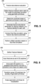
- Fig. 5 illustrates a sequence of operations 400 capable of being implemented in data processing system 10 to evaluate fracture abundance within a subsurface formation.
- a fracture network is defined within the cells of a three-dimensional model using a plurality of geometric primitives.
- a fracture network is generated based on data, for example in part from outcrop and/or seismic data, which are used to generate two-dimensional (2D) polylines.
- the fracture network is generated by growing or expanding the 2D polylines in one or more directions and representing the resulting shapes using geometric primitives, with all polylines grown in the same direction (e.g., horizontally or vertically), or with different polylines grown in different directions.
- a fracture network may be generated manually (e.g., through a computer interface) and/or based on collected data (e.g., from geomechanical properties).
- a polyline in this regard, refers to a line comprised of one or more line segments
- a two-dimensional polyline is a polyline comprised of one or more line segments that lie within the same plane.
- the polylines are referred to as two-dimensional polylines, such polylines may still be one-dimensional entities in some instances, e.g., where such polylines include only one line segment or where the segments of such polylines extend along the same axis.
- the combined areas of the geometric primitives within at least a subset of the cells of the 3D model are determined by summing together the areas of individual geometric primitives within each of the cells.
- a fracture abundance parameter is generated for the fracture network.
- the fracture abundance parameter may include a fracture density such as a P 32 value for one or more cells in the 3D model. In other embodiments, other values indicative of fracture abundance may be generated from the determined combined areas.
- the fracture abundance parameter may then be used for various purposes in various embodiments of the invention.
- the fracture abundance parameter may be used in fluid flow simulation using the same or a different 3D model of the subsurface formation.
- the results of the fluid flow simulation may be used to perform various oilfield operations, e.g., drilling a production and/or injection well, developing a well plan, determining a well trajectory, managing production, mine planning, civil engineering (e.g.: slope stability, tunneling), geotechnical ground control applications, etc.
- a directly-calculated fracture abundance parameter such as the directly-calculated P 32 value described herein may be used in some embodiments to better constrain and validate a fracture network and/or define correction factors to correct a relative P 32 value inferred from borehole data and interpolated in a 3D grid.
- the information generated during the various operations described above may also be visualized, e.g., within a graphical tool provided in an E&P platform, including both visualization of a generated fracture network as well as visualization of fracture abundance parameters calculated therefor. Further, it will be appreciated that the various operations may be performed by different tools, and that the operations need not be performed by or within a single tool.
- a fracture network is defined in block 402 of Fig. 5 in various manners in different embodiments.
- Fig. 6 illustrates the sequence of operations that "grows" or expands three-dimensional fractures from two-dimensional polylines and represents those three-dimensional fractures using one or more geometric primitives.
- fractures are input as a set of two-dimensional polylines, i.e., lines defined by two distinct points and thus having a length along an axis extending between those points, for example.
- the polylines may be generated, for example, from seismic data, from outcropping data, from borehole images, and, as discussed in greater detail below, from geomechanical data, among other sources.
- the 2D polylines may be defined within a common plane such as a two-dimensional map representing a planar slice taken through the subsurface formation, although the invention is not so limited.
- each 2D polyline is grown or expanded in a predetermined direction and with a predetermined shape and aspect ratio, i.e., a ratio that controls the amount of growth in the predetermined direction relative to the length of a polyline.
- the predetermined shape may be selected from different potential shapes capable of representing a fracture.
- the shape is rectangular or elliptical, although examples not forming part of the present invention may not be so constrained. Rectangular shapes may be favored for performance reasons, while elliptical shapes may be favored for accuracy as many fractures have a profile more closely matching that of an ellipse.
- expanding or growing a polyline along a predetermined direction may be considered to include expanding or growing the polyline in two opposite directions, e.g., equidistant from the polyline, or in some instances, different distances from the polyline. Further, expanding or growing a polyline along a predetermined direction generally results in the polyline being expanded within a plane that contains the polyline, referred to herein as a containing plane for the polyline.
- a single direction, shape and aspect ratio may be used to grow all polylines, while in other embodiments the direction, shape and/or aspect ratio may be varied for different polylines.
- the direction, shape and/or aspect ratio may be manually input by a user in some embodiments, while in other embodiments, one or more of these inputs may be determined programmatically.
- an optimizer may apply different inputs to generate different three-dimensional fracture networks that may each be used to determine different fracture abundance parameters, and these different parameters may be used in fluid flow simulations and matched against collected data to determine the combination of inputs that best matches observed data.
- the respective containing planes of different polylines may in some embodiments extend in a same direction or different directions relative to a common plane within which the polylines are disposed, and further, in some embodiments, the respective containing planes may be substantially orthogonal to such a common plane, e.g., being substantially vertical relative to a substantially horizontal common plane.
- each grown 2D polyline is transformed into a plurality of geometric primitives, namely triangles in the present invention, to represent the grown shape.
- the geometric primitives may optionally be output for visualization or other purposes.
- the geometric primitives may be output in a TSURF file format for import and display in the PETREL E&P platform.
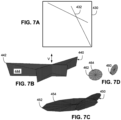
- Figs. 7A-7D further illustrate the transformation of 2D polylines into 3D sets of geometric primitives, and in the case where the 2D polylines are provided in the form of a horizontal digitized fracture map such as may be generated from seismic or outcrop data, and grown in a vertical direction.
- Fig. 7A in particular, illustrates a fracture map 430 including a pair of intersecting 2D polylines 432.
- Figs. 7B, 7C and 7D respectively illustrate the transformation of polylines 432 into rectangular, elliptical and circular shapes, respectively.
- polylines 432 may be grown into rectangular shapes 440, each formed from four points or nodes 442 and two triangles 444.
- polylines 432 may alternately be grown into elliptical shapes 450, each formed from 13 points or nodes 452 and 12 triangles 454.
- Fig. 7D also illustrates circular shapes 460, which are a special case of elliptical shapes where the radius An (semi-axis longest of an ellipse) and Bn (semi-axis shortest of an ellipse) are equal.
- a fracture abundance parameter may be calculated for a fracture network in a number of different manners consistent with the invention. Further, in some embodiments, a 3D observation grid may be generated after defining a fracture network based upon the minimum and maximum longitude/latitude and depth of the fracture network, and using a selected unit cell size to provide the desired resolution for fracture abundance parameter calculations.
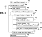
- Fig. 8 next illustrates an example sequence of operations 480 suitable for implementing blocks 404 and 406.
- the fracture network is derived from 2D polylines in a horizontal fracture map and grown in a vertical direction, and that the fracture abundance parameter calculated is a P 32 fracture density value for each cell within an observation grid.
- the calculation of P 32 in the 3D grid may in some embodiments be performed by column along the vertical Z-axis, and in some embodiments, may organize or store geometric primitives from the fracture network in an octree or other spatially-organized data structure to optimize calculations.
- Sequence of operations 480 begins in block 482 by creating a new 3D grid property for a P 32 value. For each cell i,j,k (block 484), an Area_Sum variable is initialized to zero (block 486). Next, for each fracture in the fracture network (block 488) and for each geometric primitive in the fracture (block 490), the sequence calls the ClipInsideCell function (block 492) to create a clipped primitive including only that portion of the primitive that is inside the current cell.
- Block 494 then calls an AreaFromProjections function (discussed in greater detail below) on the clipped primitive to calculate the area of the primitive, and the result of this function is added to the Area_Sum variable (block 496). This process is then repeated for every primitive in every fracture, resulting in Area_Sum storing the combined areas of the fractures within the cell. As such, block 498 divides Area_Sum by the Unit Volume of the cell, resulting in the determination of the P 32 value for that cell. Each cell in the grid is thereafter processed in a similar manner, and the result is returned in block 499 as a 3D matrix of P 32 values.
- AreaFromProjections function discussed in greater detail below
- a generated fracture abundance parameter may be used for visualization, among other purposes.
- Fig. 9 illustrates two visualizations 550, 552 of a 3D volume or grid used to calculate a P 32 fracture density value for the 2D polylines 432 illustrated in Fig. 7A and grown into rectangular shapes as illustrated in Fig. 7B .
- visualization 550 the distribution of the P 32 fracture density parameter throughout the full grid is illustrated, while in visualization 552, the distribution is limited to a horizontal layer through the grid.
- Shadings or colors denote the varying values of the P 32 parameter.
- geometric primitive projection may be used to reduce the computational resources and/or the latency associated with fracture abundance parameter determinations, e.g., to implement the AreaFromProjections function discussed above.
- fracture abundance parameter determinations may be based in part on determining a combined sum of the areas of geometric primitives such as triangular elements within each cell or volume of a three-dimensional observation grid. Consequently, in many embodiments, a fundamental operation that generally consumes a significant portion of the employed computational resources is evaluating the area of a triangle in a cell, with the understanding that the triangle can cut the cell and thus project at least partially outside of the cell.
- Some embodiments consistent with the invention may incorporate primitive projection to accelerate the determination of the area of a geometric primitive such as a triangular element inside a cell, such that the evaluation of fracture abundance may include at least the operations of defining a fracture network within a plurality of cells of a three-dimensional model of a subsurface formation using a plurality of geometric primitives, determining an area of the plurality of geometric primitives within at least a subset of the plurality of cells by summing areas of individual geometric primitives within each of the subset of cells, including determining an area of a first geometric primitive among the plurality of geometric primitives within a first cell in the subset of cells by projecting the first geometric primitive onto each of first, second and third orthogonal planes respectively aligned with faces of the first cell to define respective first, second and third projections and calculating areas of each of the first, second and third projections, and determining a fracture abundance parameter for the fracture network from the determined area of the plurality of geometric primitives.
- the herein-described technique may also in some embodiments shift the barrier to evaluate any triangular element of any orientation in a 3D Cartesian space, such that rapid calculations may be made of planar triangular elements of any orientation, and generally without involving classical heavy trigonometric algorithms to calculate the area.
- the area of any subsurface structure capable of being represented by triangular elements may be determined in a fast and efficient manner using the herein-described techniques, so the herein-described techniques may also be used for evaluating a subsurface formation by in part defining a subsurface structure within a plurality of cells in a three-dimensional model of the subsurface formation using a plurality of geometric primitives, determining an area of the plurality of geometric primitives using projection in the manner described herein, and determining a subsurface structure parameter for the subsurface structure (e.g., a fracture abundance parameter for a fracture network, or another parameter suitable for the particular subsurface structure being modeled) from the determined area of the plurality of geometric primitives.
- a subsurface structure parameter for the subsurface structure e.g., a fracture abundance parameter for a fracture network, or another parameter suitable for the particular subsurface structure being modeled
- Primitive projection in this regard may be considered to refer to an operation that projects a shape of any arbitrary orientation within a three-dimensional cell onto a plane that is aligned with a face of a regular cubic cell.
- a face of a regular cubic cell is generally parallel to a plane formed by two of the three axes of a three-dimensional Cartesian coordinate system, e.g., where points or nodes are identified by (x, y, z) values on mutually-orthogonal X, Y and Z axes, each cell will generally have two faces parallel with each of XY, YZ and ZX planes defined by the X, Y and Z axes.
- Projection onto a plane aligned with a face of a regular cubic cell may therefore include projection onto a plane that is either coextensive with or parallel to a face of a cell, and thus coextensive with or parallel to the XY, YZ or ZX planes defined for a grid of regular cubic cells.
- Fig. 10 illustrates the determination of the length L of an arbitrarily oriented one-dimensional line within a two-dimensional plane through projection of the line onto the two orthogonal axes X and Y.
- Fig. 11 illustrates an extension of this principle into a three-dimensional space, where the area A of an arbitrarily oriented two-dimensional planar shape 560 within a three-dimensional volume may be determined through projection of the shape onto the three orthogonal planes XY, ZX and YZ planes to form three projections 562, 564 and 566 having areas A xy , A zx and A yz respectively.
- a net effect of projecting a shape onto a plane aligned with a face of a regular cubic cell is that all points or nodes of the projection is the reduction of the 3D problem into a simple 2D problem, thus simplifying the determination of the area of a projection into a less computationally-expensive operation.
- the location of each point or node of a projection of a shape thus may be represented by the other two coordinates. Consequently, assuming that shape 560 is defined by three points (x 1 , y 1 , , z 1 ), (x 2 , y 2 , z 2 ) and (x 3 , y 3 , z 3 ), the projections onto the three planes XY, ZX and YZ may be considered to be defined by points:
- the area may be determined by projecting the triangle onto the three principal planes and sum the squares of the resulting projected areas.
- clipping may also be performed in connection with projection in order to determine the area of a primitive within a cell, generally prior to projecting the primitive.
- Fig. 11 illustrates the clipped portions of both the primitive 560 and each projection 562-566 using darker shading than the portions that fall outside of the cell. Consequently, the coordinates of each point of the primitives may be compared with the coordinates of the boundary of the cell to replace any point disposed outside of the boundary of the cell with one or more points along the boundary of the cell.
- the areas of clipped projections may be determined by splitting a clipped projection into a plurality of triangles and summing the areas of the triangles forming the clipped projection.
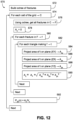
- Sequence 570 in the illustrated embodiment, utilizes an octree or other data structure to spatially organize geometric primitives, here triangles, of a defined fracture network, and thereby facilitate lookup of the triangles that are within each cell.
- Various types of data structures and/or lookup algorithms including algorithms based on other types of binary and/or spatially-partitioned trees, may be used in other embodiments.
- Block 572 initially builds an octree of the fractures in the fracture network. Then, for each cell C of the grid (block 574), the octree is accessed to generate a set F of all fractures that at least partially intersect the cell C (block 576). A combined area variable A C is then reset (block 578), and each fracture f in set F (block 580), and each triangle t defining fracture f (block 582) is processed by projecting the area of the triangle t onto planes XY, ZX and YZ (block 584, 586 and 588), with the areas of the projections stored in A xy , A zx and A yz respectively.
- fracture abundance evaluation may be based at least in part on geomechanical simulation based on mechanical properties of a subsurface formation.
- fracture density and/or fracture height may be estimated from geomechanical simulation using mechanical properties of a subsurface formation, e.g., as collected from well logging.
- a balance energy operation may be used to estimate a P 10 fracture density and fracture height from well log data in some embodiments.
- Fig. 13 illustrates an example sequence of operations 600 for evaluating fracture abundance based on geomechanical simulation based on mechanical properties.
- a P 10 fracture density and fracture height for a subsurface formation may be determined from mechanical properties derived from well log data, e.g., one or more of Young's modulus, Poisson's ratio, friction coefficient, cohesion, fault dip, effective vertical stress, fluid pressure, and crack surface energy, among others.
- Such calculations may be based on a balance energy approach, and may be performed, for example, using geomechanical simulation functionality available in the PETREL, TECHLOG or FAULT MODELER software available from Schlumberger and its affiliates, although it will be appreciated that the invention is not limited to use with such software.
- an input file is created including 2D polyline representations of fractures associated with fracture height, and taken along a vertical trace corresponding to the well from which the geomechanical properties were obtained that extends along the well (block 604), and then each 2D polyline is grown in a similar manner to that described above in connection with Fig. 6 , but with the direction of growth being horizontal for a vertical well (block 606).
- An aspect ratio may also be used to control the growth, and various shapes, including rectangular or elliptical shapes. Again similar to Fig. 6 , the grown shapes are transformed into geometric primitives (block 608), and then similar to Fig.
- a fracture abundance parameter for the fracture network e.g., a P 32 fracture density value for each cell, is determined (block 610).
- Fluid flow simulation (block 612) and/or an oilfield operation (block 614) may then be performed, again similar to Fig. 5 .
- Fig. 14 illustrates a visualization 620 of fracture growth around an example well based upon geomechanical properties
- visualization 622 illustrates a vertical section of an observation grid containing the directly-calculated "true" P 32 value, with legend 624 mapping the shading to different ranges of P 32 values.
- some embodiments of the invention support the evaluation of true P 32 fracture density based on a 1D geomechanical method.
- reservoir simulations in some embodiments may be better constrained, particularly for vertical wells that may run parallel to the fracture network, and may not detect fracture at in some circumstances leading to an optimized production of the reservoir through flow simulation.
- the results of the aforementioned evaluation may be used for other purposes, e.g., for derisking, drilling and fracture connectivity. This is particularly true in certain situations. For example, as illustrated in Fig. 15 , well log data from a vertical well A may detect one fracture along layer 2 while nothing is observed in layers 3, 4 and 5. Well B may detect a fracture on layer 4, with nothing observed in in the other layers.
- well C may not detect a fracture at all.
- the herein-described techniques may therefore address these situations and estimate 3D fracture abundance with better prediction along wells, which may be used to populate a 3D grid for fracture network generation instead of a direct conventional measure of fracture abundance such as a P 10c , value.
- three-dimensional fracture abundance evaluation in some embodiments may use area determination operations other than the herein-described projection-based area determinations, as well as that projection-based area determinations may have other applications beyond that of fracture abundance evaluation.
- various operations may be used to generate or define a fracture network, so the invention is not limited to the particular geomechanical simulation-based approach disclosed herein, and further, other three-dimensional fracture abundance evaluation approaches beyond those described herein may be used to evaluate fracture abundance using mechanical properties, as long as they fall within the scope of protection that is defined by the appended claims.
- embodiments may be utilized in conjunction with a handheld system (i.e., a phone, wrist or forearm mounted computer, tablet, or other handheld device), portable system (i.e., a laptop or portable computing system), a fixed computing system (i.e., a desktop, server, cluster, or high performance computing system), or across a network (i.e., a cloud-based system).
- a handheld system i.e., a phone, wrist or forearm mounted computer, tablet, or other handheld device
- portable system i.e., a laptop or portable computing system
- a fixed computing system i.e., a desktop, server, cluster, or high performance computing system
- a network i.e., a cloud-based system
Landscapes
- Life Sciences & Earth Sciences (AREA)
- Physics & Mathematics (AREA)
- Engineering & Computer Science (AREA)
- General Life Sciences & Earth Sciences (AREA)
- Geology (AREA)
- Mining & Mineral Resources (AREA)
- General Physics & Mathematics (AREA)
- Geophysics (AREA)
- Geochemistry & Mineralogy (AREA)
- Fluid Mechanics (AREA)
- Environmental & Geological Engineering (AREA)
- Geophysics And Detection Of Objects (AREA)
- Geometry (AREA)
- Computer Graphics (AREA)
- Software Systems (AREA)
- Theoretical Computer Science (AREA)
- Remote Sensing (AREA)
- General Engineering & Computer Science (AREA)
- Operations Research (AREA)
- Investigating Strength Of Materials By Application Of Mechanical Stress (AREA)
Claims (8)
- Procédé mis en œuvre par ordinateur d'évaluation de l'abondance de fractures dans une formation souterraine, le procédé comprenant :a) la définition (402) d'un réseau de fractures à l'intérieur d'une pluralité de cellules d'un modèle tridimensionnel de la formation souterraine à l'aide d'une pluralité de primitives géométriques, où le réseau de fractures et le modèle tridimensionnel sont générés en fonction des données obtenues à partir d'une étude de la formation souterraine, dans lequel la définition (402) du réseau de fractures comporte l'expansion, à l'intérieur d'un plan de confinement respectif, de chaque polyligne d'une pluralité de polylignes bidimensionnelles (432) représentant des fractures dans la formation souterraine, dans lequel :une polyligne bidimensionnelle comprend un ou plusieurs segments de ligne situés à l'intérieur d'un même plan ;chaque primitive de la pluralité de primitives géométriques est un élément triangulaire ; etl'expansion de chaque polyligne de la pluralité de polylignes bidimensionnelles comporte l'expansion dans la direction du plan de confinement respectifune première polyligne bidimensionnelle parmi la pluralité de polylignes bidimensionnelles soit sous une forme sensiblement rectangulaire représentée par des premier et second éléments triangulaires définis par quatre noeuds, soit sous une forme sensiblement elliptique représentée par douze éléments triangulaires définis par treize noeuds ;b) la détermination (404) d'une aire de la pluralité de primitives géométriques à l'intérieur d'au moins un sous-ensemble de la pluralité de cellules par sommation des aires des primitives géométriques individuelles à l'intérieur de chaque sous-ensemble de cellules, dans lequel la détermination de l'aire de la pluralité de primitives géométriques à l'intérieur du sous-ensemble de la pluralité de cellules comporte en outre :l'organisation (482) de la pluralité de primitives géométriques à l'intérieur d'une structure de données organisée spatialement ;l'accès (484) à la structure de données organisée spatialement lorsque des aires de brouillard des primitives géométriques individuelles à l'intérieur de chaque sous-ensemble de cellules pour déterminer lesquelles de la pluralité de primitives géométriques sont au moins partiellement à l'intérieur de chaque sous-ensemble de cellules ; etla coupure des primitives géométriques individuelles qui se trouvent partiellement à l'intérieur de chaque sous-ensemble de cellules ; etc) la détermination (406) d'un paramètre d'abondance de fractures pour le réseau de fractures à partir de l'aire déterminée de la pluralité de primitives géométriques.
- Procédé selon la revendication 1, dans lequel la définition du réseau de fractures comporte en outre la représentation de chaque polyligne bidimensionnelle par les primitives géométriques multiples disposées dans le plan de confinement respectif.
- Procédé selon la revendication 1 ou 2, dans lequel la pluralité de polylignes bidimensionnelles sont disposées dans un plan commun, et dans lequel les plans de confinement respectifs s'étendent dans une même direction par rapport au plan commun.
- Procédé selon l'une quelconque des revendications 1 à 3, dans lequel l'expansion de chaque polyligne de la pluralité de polylignes bidimensionnelles comporte l'utilisation d'un rapport d'aspect pour contraindre l'expansion de chacune de la pluralité de polylignes bidimensionnelles à l'intérieur des plans de confinement respectifs par rapport à la longueur de fracture.
- Procédé selon une quelconque revendication précédente, dans lequel l'expansion de chaque polyligne de la pluralité de polylignes bidimensionnelles comporte l'expansion d'une première polyligne bidimensionnelle parmi la pluralité de polylignes bidimensionnelles en une forme sensiblement elliptique et dans lequel la forme sensiblement elliptique est une forme sensiblement circulaire.
- Procédé selon une quelconque revendication précédente, dans lequel la détermination du paramètre d'abondance de fractures comporte la détermination d'une densité de fractures à l'intérieur de chacune des cellules du sous-ensemble de cellules en divisant les aires sommées de primitives géométriques individuelles dans celles-ci par un volume de celles-ci.
- Appareil comprenant :au moins une unité de traitement ; etle code de programme configuré sous l'effet de l'exécution par ladite au moins une unité de traitement pour évaluer l'abondance de fractures dans une formation souterraine en réalisant le procédé selon une quelconque revendication précédente.
- Produit-programme comprenant :un support lisible par ordinateur ; etle code de programme mémorisé dans le support lisible par ordinateur et configuré lors de l'exécution par au moins une unité de traitement pour évaluer l'abondance de fractures dans une formation souterraine en réalisant le procédé selon l'une quelconque des revendications 1 à 6.
Applications Claiming Priority (2)
| Application Number | Priority Date | Filing Date | Title |
|---|---|---|---|
| US15/150,268 US10113421B2 (en) | 2016-05-09 | 2016-05-09 | Three-dimensional fracture abundance evaluation of subsurface formations |
| PCT/US2017/026738 WO2017196475A2 (fr) | 2016-05-09 | 2017-04-10 | Évaluation tridimensionnelle d'abondance de fractures de formations souterraines |
Publications (3)
| Publication Number | Publication Date |
|---|---|
| EP3455459A2 EP3455459A2 (fr) | 2019-03-20 |
| EP3455459A4 EP3455459A4 (fr) | 2020-01-15 |
| EP3455459B1 true EP3455459B1 (fr) | 2025-02-12 |
Family
ID=60243939
Family Applications (1)
| Application Number | Title | Priority Date | Filing Date |
|---|---|---|---|
| EP17796530.8A Active EP3455459B1 (fr) | 2016-05-09 | 2017-04-10 | Évaluation d'abondance de fractures tridimensionnelles de formations souterraines |
Country Status (4)
| Country | Link |
|---|---|
| US (1) | US10113421B2 (fr) |
| EP (1) | EP3455459B1 (fr) |
| CA (1) | CA3023651A1 (fr) |
| WO (1) | WO2017196475A2 (fr) |
Families Citing this family (8)
| Publication number | Priority date | Publication date | Assignee | Title |
|---|---|---|---|---|
| US10650107B2 (en) * | 2016-05-09 | 2020-05-12 | Schlumberger Technology Corporation | Three-dimensional subsurface formation evaluation using projection-based area operations |
| US10853533B2 (en) | 2016-05-09 | 2020-12-01 | Schlumberger Technology Corporation | Three-dimensional fracture abundance evaluation of subsurface formation based on geomechanical simulation of mechanical properties thereof |
| CN110892255B (zh) * | 2017-07-07 | 2024-03-01 | 佳能株式会社 | 从图像检测缺陷的图像处理装置、方法和存储介质 |
| CN108648261A (zh) * | 2018-03-25 | 2018-10-12 | 成都明镜视觉科技有限公司 | 一种三维模型定义方法 |
| WO2019204648A1 (fr) * | 2018-04-18 | 2019-10-24 | Borehole Seismic, Llc | Imagerie sismique composite haute résolution, systèmes et procédés |
| CN113283147B (zh) * | 2021-06-09 | 2022-09-16 | 深圳大学 | 三维Cohesive单元全局嵌入方法 |
| CN114218787B (zh) * | 2021-12-10 | 2024-10-01 | 中国矿业大学 | 一种基于四维地质力学的断层相关裂缝定量预测方法 |
| CN120522785B (zh) * | 2025-06-11 | 2025-12-30 | 河北三恩油气工程技术服务有限公司 | 基于微地震震源扫描的压裂裂缝密度量化分析方法及系统 |
Family Cites Families (20)
| Publication number | Priority date | Publication date | Assignee | Title |
|---|---|---|---|---|
| US8423337B2 (en) | 2007-08-24 | 2013-04-16 | Exxonmobil Upstream Research Company | Method for multi-scale geomechanical model analysis by computer simulation |
| BRPI0820830B1 (pt) | 2007-12-14 | 2019-08-13 | Exxonmobil Upstream Res Co | método para modelar em um computador uma região física |
| US8803878B2 (en) | 2008-03-28 | 2014-08-12 | Schlumberger Technology Corporation | Visualizing region growing in three dimensional voxel volumes |
| US8166042B1 (en) | 2008-04-14 | 2012-04-24 | Google Inc. | Height based indexing |
| US9607007B2 (en) | 2009-12-23 | 2017-03-28 | Schlumberger Technology Corporation | Processing of geological data |
| US8731889B2 (en) | 2010-03-05 | 2014-05-20 | Schlumberger Technology Corporation | Modeling hydraulic fracturing induced fracture networks as a dual porosity system |
| US8731887B2 (en) | 2010-04-12 | 2014-05-20 | Exxonmobile Upstream Research Company | System and method for obtaining a model of data describing a physical structure |
| CA2806197A1 (fr) * | 2010-08-05 | 2012-02-09 | Exxonmobil Upstream Research Company | Obtention de donnees a partir d'un modele terrestre au moyen de descripteurs fonctionnels |
| US8898046B2 (en) | 2010-12-10 | 2014-11-25 | Baker Hughes Incorporated | Method to improve reservoir simulation and recovery from fractured reservoirs |
| CA2915625C (fr) | 2011-03-11 | 2021-08-03 | Schlumberger Canada Limited | Procede d'etalonnage de geometrie de fracture a des evenements microsismiques |
| AU2012322729B2 (en) | 2011-10-11 | 2015-12-24 | Schlumberger Technology B.V. | System and method for performing stimulation operations |
| AU2012332270A1 (en) | 2011-11-04 | 2014-05-29 | Schlumberger Technology B.V. | Modeling of interaction of hydraulic fractures in complex fracture networks |
| US20140058713A1 (en) | 2012-08-21 | 2014-02-27 | Schlumberger Technology Corporation | Seismic modeling system and method |
| AU2013377864B2 (en) * | 2013-02-11 | 2016-09-08 | Exxonmobil Upstream Research Company | Reservoir segment evaluation for well planning |
| US20140358510A1 (en) | 2013-05-29 | 2014-12-04 | Chevron U.S.A. Inc. | System and method for characterizing uncertainty in subterranean reservoir fracture networks |
| US9416630B2 (en) | 2013-06-18 | 2016-08-16 | Baker Hughes Incorporated | Grid calculation for fluid flow modeling |
| FR3010192B1 (fr) * | 2013-09-04 | 2017-04-28 | Ifp Energies Now | Procede d'exploitation d'un gisement souterrain comprenant au moins un affleurement geologique au moyen d'une photogrammetrie |
| US10572611B2 (en) * | 2016-04-29 | 2020-02-25 | Exxonmobil Upstream Research Company | Method and system for characterizing fractures in a subsurface region |
| US10650107B2 (en) | 2016-05-09 | 2020-05-12 | Schlumberger Technology Corporation | Three-dimensional subsurface formation evaluation using projection-based area operations |
| US10853533B2 (en) | 2016-05-09 | 2020-12-01 | Schlumberger Technology Corporation | Three-dimensional fracture abundance evaluation of subsurface formation based on geomechanical simulation of mechanical properties thereof |
-
2016
- 2016-05-09 US US15/150,268 patent/US10113421B2/en active Active
-
2017
- 2017-04-10 WO PCT/US2017/026738 patent/WO2017196475A2/fr not_active Ceased
- 2017-04-10 EP EP17796530.8A patent/EP3455459B1/fr active Active
- 2017-04-10 CA CA3023651A patent/CA3023651A1/fr active Pending
Non-Patent Citations (1)
| Title |
|---|
| DERSHOWITZ W.S ET AL: "Interpretation of fracture spacing and intensity", THE 33RD U.S. SYMPOSIUM ON ROCK MECHANICS (USRMS), 3 June 1992 (1992-06-03), Rotterdam, pages 757 - 766, XP055875195, Retrieved from the Internet <URL:https://onepetro.org/ARMAUSRMS/proceedings-abstract/ARMA92/All-ARMA92/ARMA-92-0757/130438> [retrieved on 20211221] * |
Also Published As
| Publication number | Publication date |
|---|---|
| WO2017196475A3 (fr) | 2018-07-26 |
| EP3455459A4 (fr) | 2020-01-15 |
| WO2017196475A2 (fr) | 2017-11-16 |
| US20170323477A1 (en) | 2017-11-09 |
| CA3023651A1 (fr) | 2017-11-16 |
| US10113421B2 (en) | 2018-10-30 |
| EP3455459A2 (fr) | 2019-03-20 |
Similar Documents
| Publication | Publication Date | Title |
|---|---|---|
| EP3455654B1 (fr) | Évaluation d'abondance de fractures tridimensionnelles d'une formation souterraine sur la base d'une simulation géomécanique des propriétés mécaniques de celle-ci | |
| EP3455459B1 (fr) | Évaluation d'abondance de fractures tridimensionnelles de formations souterraines | |
| EP3371628B1 (fr) | Génération de vecteur de déplacement de faille et de zone d'endommagement de faille dans une formation souterraine à l'aide d'une fonction stratigraphique | |
| US20160124116A1 (en) | Generation of structural elements for subsurface formation using stratigraphic implicit function | |
| EP3018502A2 (fr) | Modélisation des fractures conductrices de fluides dans une grille de simulation de réservoir | |
| US9388682B2 (en) | Hazard avoidance analysis | |
| CA2911107C (fr) | Moteur a geometrie par couche locale dote d'une zone de travail produite par un tampon defini par rapport a une trajectoire de puits de forage | |
| EP3338115A1 (fr) | Simulations de réservoir incluant des réseaux de fracture | |
| US10650107B2 (en) | Three-dimensional subsurface formation evaluation using projection-based area operations | |
| US12333430B2 (en) | Super resolution machine learning model for seismic visualization generation | |
| CA3040439C (fr) | Evaluation de champ petrophysique a l'aide d'une carte auto-organisatrice | |
| CN112292714B (zh) | 基于断层辐射的网格隔分 | |
| CA3023655C (fr) | Evaluation d'abondance de fractures tridimensionnelles d'une formation souterraine sur la base d'une simulation geomecanique des proprietes mecaniques de celle-ci | |
| US11175423B2 (en) | Real time deformation of seismic slices using programmable shaders |
Legal Events
| Date | Code | Title | Description |
|---|---|---|---|
| STAA | Information on the status of an ep patent application or granted ep patent |
Free format text: STATUS: THE INTERNATIONAL PUBLICATION HAS BEEN MADE |
|
| PUAI | Public reference made under article 153(3) epc to a published international application that has entered the european phase |
Free format text: ORIGINAL CODE: 0009012 |
|
| STAA | Information on the status of an ep patent application or granted ep patent |
Free format text: STATUS: REQUEST FOR EXAMINATION WAS MADE |
|
| 17P | Request for examination filed |
Effective date: 20181205 |
|
| AK | Designated contracting states |
Kind code of ref document: A2 Designated state(s): AL AT BE BG CH CY CZ DE DK EE ES FI FR GB GR HR HU IE IS IT LI LT LU LV MC MK MT NL NO PL PT RO RS SE SI SK SM TR |
|
| AX | Request for extension of the european patent |
Extension state: BA ME |
|
| DAV | Request for validation of the european patent (deleted) | ||
| DAX | Request for extension of the european patent (deleted) | ||
| A4 | Supplementary search report drawn up and despatched |
Effective date: 20191217 |
|
| RIC1 | Information provided on ipc code assigned before grant |
Ipc: G01V 99/00 20090101AFI20191211BHEP Ipc: G01V 1/30 20060101ALN20191211BHEP |
|
| STAA | Information on the status of an ep patent application or granted ep patent |
Free format text: STATUS: EXAMINATION IS IN PROGRESS |
|
| 17Q | First examination report despatched |
Effective date: 20220105 |
|
| REG | Reference to a national code |
Ref country code: DE Ref legal event code: R079 Free format text: PREVIOUS MAIN CLASS: E21B0047010000 Ipc: G01V0020000000 Ref country code: DE Ref legal event code: R079 Ref document number: 602017087723 Country of ref document: DE Free format text: PREVIOUS MAIN CLASS: E21B0047010000 Ipc: G01V0020000000 |
|
| GRAP | Despatch of communication of intention to grant a patent |
Free format text: ORIGINAL CODE: EPIDOSNIGR1 |
|
| STAA | Information on the status of an ep patent application or granted ep patent |
Free format text: STATUS: GRANT OF PATENT IS INTENDED |
|
| RIC1 | Information provided on ipc code assigned before grant |
Ipc: G01V 20/00 20240101AFI20240815BHEP |
|
| INTG | Intention to grant announced |
Effective date: 20240827 |
|
| GRAS | Grant fee paid |
Free format text: ORIGINAL CODE: EPIDOSNIGR3 |
|
| GRAA | (expected) grant |
Free format text: ORIGINAL CODE: 0009210 |
|
| STAA | Information on the status of an ep patent application or granted ep patent |
Free format text: STATUS: THE PATENT HAS BEEN GRANTED |
|
| AK | Designated contracting states |
Kind code of ref document: B1 Designated state(s): AL AT BE BG CH CY CZ DE DK EE ES FI FR GB GR HR HU IE IS IT LI LT LU LV MC MK MT NL NO PL PT RO RS SE SI SK SM TR |
|
| REG | Reference to a national code |
Ref country code: GB Ref legal event code: FG4D |
|
| REG | Reference to a national code |
Ref country code: CH Ref legal event code: EP |
|
| REG | Reference to a national code |
Ref country code: DE Ref legal event code: R096 Ref document number: 602017087723 Country of ref document: DE |
|
| REG | Reference to a national code |
Ref country code: IE Ref legal event code: FG4D |
|
| REG | Reference to a national code |
Ref country code: NL Ref legal event code: FP |
|
| PGFP | Annual fee paid to national office [announced via postgrant information from national office to epo] |
Ref country code: NL Payment date: 20250521 Year of fee payment: 9 |
|
| PG25 | Lapsed in a contracting state [announced via postgrant information from national office to epo] |
Ref country code: RS Free format text: LAPSE BECAUSE OF FAILURE TO SUBMIT A TRANSLATION OF THE DESCRIPTION OR TO PAY THE FEE WITHIN THE PRESCRIBED TIME-LIMIT Effective date: 20250512 |
|
| PG25 | Lapsed in a contracting state [announced via postgrant information from national office to epo] |
Ref country code: FI Free format text: LAPSE BECAUSE OF FAILURE TO SUBMIT A TRANSLATION OF THE DESCRIPTION OR TO PAY THE FEE WITHIN THE PRESCRIBED TIME-LIMIT Effective date: 20250212 |
|
| PG25 | Lapsed in a contracting state [announced via postgrant information from national office to epo] |
Ref country code: PL Free format text: LAPSE BECAUSE OF FAILURE TO SUBMIT A TRANSLATION OF THE DESCRIPTION OR TO PAY THE FEE WITHIN THE PRESCRIBED TIME-LIMIT Effective date: 20250212 |
|
| PG25 | Lapsed in a contracting state [announced via postgrant information from national office to epo] |
Ref country code: ES Free format text: LAPSE BECAUSE OF FAILURE TO SUBMIT A TRANSLATION OF THE DESCRIPTION OR TO PAY THE FEE WITHIN THE PRESCRIBED TIME-LIMIT Effective date: 20250212 |
|
| REG | Reference to a national code |
Ref country code: LT Ref legal event code: MG9D |
|
| PG25 | Lapsed in a contracting state [announced via postgrant information from national office to epo] |
Ref country code: IS Free format text: LAPSE BECAUSE OF FAILURE TO SUBMIT A TRANSLATION OF THE DESCRIPTION OR TO PAY THE FEE WITHIN THE PRESCRIBED TIME-LIMIT Effective date: 20250612 |
|
| PGFP | Annual fee paid to national office [announced via postgrant information from national office to epo] |
Ref country code: NO Payment date: 20250508 Year of fee payment: 9 |
|
| PG25 | Lapsed in a contracting state [announced via postgrant information from national office to epo] |
Ref country code: HR Free format text: LAPSE BECAUSE OF FAILURE TO SUBMIT A TRANSLATION OF THE DESCRIPTION OR TO PAY THE FEE WITHIN THE PRESCRIBED TIME-LIMIT Effective date: 20250212 |
|
| PG25 | Lapsed in a contracting state [announced via postgrant information from national office to epo] |
Ref country code: PT Free format text: LAPSE BECAUSE OF FAILURE TO SUBMIT A TRANSLATION OF THE DESCRIPTION OR TO PAY THE FEE WITHIN THE PRESCRIBED TIME-LIMIT Effective date: 20250612 Ref country code: LV Free format text: LAPSE BECAUSE OF FAILURE TO SUBMIT A TRANSLATION OF THE DESCRIPTION OR TO PAY THE FEE WITHIN THE PRESCRIBED TIME-LIMIT Effective date: 20250212 |
|
| PGFP | Annual fee paid to national office [announced via postgrant information from national office to epo] |
Ref country code: FR Payment date: 20250521 Year of fee payment: 9 |
|
| PG25 | Lapsed in a contracting state [announced via postgrant information from national office to epo] |
Ref country code: GR Free format text: LAPSE BECAUSE OF FAILURE TO SUBMIT A TRANSLATION OF THE DESCRIPTION OR TO PAY THE FEE WITHIN THE PRESCRIBED TIME-LIMIT Effective date: 20250513 Ref country code: BG Free format text: LAPSE BECAUSE OF FAILURE TO SUBMIT A TRANSLATION OF THE DESCRIPTION OR TO PAY THE FEE WITHIN THE PRESCRIBED TIME-LIMIT Effective date: 20250212 |
|
| REG | Reference to a national code |
Ref country code: AT Ref legal event code: MK05 Ref document number: 1766551 Country of ref document: AT Kind code of ref document: T Effective date: 20250212 |
|
| PG25 | Lapsed in a contracting state [announced via postgrant information from national office to epo] |
Ref country code: SE Free format text: LAPSE BECAUSE OF FAILURE TO SUBMIT A TRANSLATION OF THE DESCRIPTION OR TO PAY THE FEE WITHIN THE PRESCRIBED TIME-LIMIT Effective date: 20250212 |
|
| PG25 | Lapsed in a contracting state [announced via postgrant information from national office to epo] |
Ref country code: SM Free format text: LAPSE BECAUSE OF FAILURE TO SUBMIT A TRANSLATION OF THE DESCRIPTION OR TO PAY THE FEE WITHIN THE PRESCRIBED TIME-LIMIT Effective date: 20250212 |
|
| PG25 | Lapsed in a contracting state [announced via postgrant information from national office to epo] |
Ref country code: DK Free format text: LAPSE BECAUSE OF FAILURE TO SUBMIT A TRANSLATION OF THE DESCRIPTION OR TO PAY THE FEE WITHIN THE PRESCRIBED TIME-LIMIT Effective date: 20250212 |
|
| PG25 | Lapsed in a contracting state [announced via postgrant information from national office to epo] |
Ref country code: IT Free format text: LAPSE BECAUSE OF FAILURE TO SUBMIT A TRANSLATION OF THE DESCRIPTION OR TO PAY THE FEE WITHIN THE PRESCRIBED TIME-LIMIT Effective date: 20250212 |
|
| PG25 | Lapsed in a contracting state [announced via postgrant information from national office to epo] |
Ref country code: AT Free format text: LAPSE BECAUSE OF FAILURE TO SUBMIT A TRANSLATION OF THE DESCRIPTION OR TO PAY THE FEE WITHIN THE PRESCRIBED TIME-LIMIT Effective date: 20250212 |
|
| PG25 | Lapsed in a contracting state [announced via postgrant information from national office to epo] |
Ref country code: EE Free format text: LAPSE BECAUSE OF FAILURE TO SUBMIT A TRANSLATION OF THE DESCRIPTION OR TO PAY THE FEE WITHIN THE PRESCRIBED TIME-LIMIT Effective date: 20250212 Ref country code: CZ Free format text: LAPSE BECAUSE OF FAILURE TO SUBMIT A TRANSLATION OF THE DESCRIPTION OR TO PAY THE FEE WITHIN THE PRESCRIBED TIME-LIMIT Effective date: 20250212 |
|
| PG25 | Lapsed in a contracting state [announced via postgrant information from national office to epo] |
Ref country code: RO Free format text: LAPSE BECAUSE OF FAILURE TO SUBMIT A TRANSLATION OF THE DESCRIPTION OR TO PAY THE FEE WITHIN THE PRESCRIBED TIME-LIMIT Effective date: 20250212 |
|
| PG25 | Lapsed in a contracting state [announced via postgrant information from national office to epo] |
Ref country code: SK Free format text: LAPSE BECAUSE OF FAILURE TO SUBMIT A TRANSLATION OF THE DESCRIPTION OR TO PAY THE FEE WITHIN THE PRESCRIBED TIME-LIMIT Effective date: 20250212 |
|
| REG | Reference to a national code |
Ref country code: DE Ref legal event code: R119 Ref document number: 602017087723 Country of ref document: DE |
|
| REG | Reference to a national code |
Ref country code: CH Ref legal event code: H13 Free format text: ST27 STATUS EVENT CODE: U-0-0-H10-H13 (AS PROVIDED BY THE NATIONAL OFFICE) Effective date: 20251125 |
|
| PG25 | Lapsed in a contracting state [announced via postgrant information from national office to epo] |
Ref country code: LU Free format text: LAPSE BECAUSE OF NON-PAYMENT OF DUE FEES Effective date: 20250410 |
|
| PLBE | No opposition filed within time limit |
Free format text: ORIGINAL CODE: 0009261 |
|
| STAA | Information on the status of an ep patent application or granted ep patent |
Free format text: STATUS: NO OPPOSITION FILED WITHIN TIME LIMIT |
|
| PG25 | Lapsed in a contracting state [announced via postgrant information from national office to epo] |
Ref country code: MC Free format text: LAPSE BECAUSE OF FAILURE TO SUBMIT A TRANSLATION OF THE DESCRIPTION OR TO PAY THE FEE WITHIN THE PRESCRIBED TIME-LIMIT Effective date: 20250212 |
|
| REG | Reference to a national code |
Ref country code: BE Ref legal event code: MM Effective date: 20250430 |
|
| PG25 | Lapsed in a contracting state [announced via postgrant information from national office to epo] |
Ref country code: DE Free format text: LAPSE BECAUSE OF NON-PAYMENT OF DUE FEES Effective date: 20251104 |
|
| PG25 | Lapsed in a contracting state [announced via postgrant information from national office to epo] |
Ref country code: BE Free format text: LAPSE BECAUSE OF NON-PAYMENT OF DUE FEES Effective date: 20250430 |
|
| PG25 | Lapsed in a contracting state [announced via postgrant information from national office to epo] |
Ref country code: CH Free format text: LAPSE BECAUSE OF NON-PAYMENT OF DUE FEES Effective date: 20250430 |
|
| 26N | No opposition filed |
Effective date: 20251113 |
|
| PGFP | Annual fee paid to national office [announced via postgrant information from national office to epo] |
Ref country code: GB Payment date: 20260324 Year of fee payment: 10 |
|
| PG25 | Lapsed in a contracting state [announced via postgrant information from national office to epo] |
Ref country code: IE Free format text: LAPSE BECAUSE OF NON-PAYMENT OF DUE FEES Effective date: 20250410 |