EP3456218A1 - Hautbehandlungsvorrichtung und verwendung eines reservoirs mit einer hautbehandlungsvorrichtung - Google Patents
Hautbehandlungsvorrichtung und verwendung eines reservoirs mit einer hautbehandlungsvorrichtung Download PDFInfo
- Publication number
- EP3456218A1 EP3456218A1 EP17191824.6A EP17191824A EP3456218A1 EP 3456218 A1 EP3456218 A1 EP 3456218A1 EP 17191824 A EP17191824 A EP 17191824A EP 3456218 A1 EP3456218 A1 EP 3456218A1
- Authority
- EP
- European Patent Office
- Prior art keywords
- reservoir
- wick
- accordance
- dispensing
- skin
- Prior art date
- Legal status (The legal status is an assumption and is not a legal conclusion. Google has not performed a legal analysis and makes no representation as to the accuracy of the status listed.)
- Withdrawn
Links
- 238000009826 distribution Methods 0.000 claims description 3
- 239000000463 material Substances 0.000 description 16
- 210000003739 neck Anatomy 0.000 description 11
- 239000006210 lotion Substances 0.000 description 10
- 238000005520 cutting process Methods 0.000 description 7
- 239000007788 liquid Substances 0.000 description 7
- 238000013461 design Methods 0.000 description 5
- 239000006260 foam Substances 0.000 description 5
- 239000000835 fiber Substances 0.000 description 3
- 241000506680 Haemulon melanurum Species 0.000 description 2
- 238000005259 measurement Methods 0.000 description 2
- 238000000034 method Methods 0.000 description 2
- 239000011148 porous material Substances 0.000 description 2
- 239000004743 Polypropylene Substances 0.000 description 1
- 239000011358 absorbing material Substances 0.000 description 1
- 230000003796 beauty Effects 0.000 description 1
- 238000001125 extrusion Methods 0.000 description 1
- 239000006261 foam material Substances 0.000 description 1
- 238000002372 labelling Methods 0.000 description 1
- -1 polypropylene Polymers 0.000 description 1
- 229920001155 polypropylene Polymers 0.000 description 1
- 238000011160 research Methods 0.000 description 1
- 230000000717 retained effect Effects 0.000 description 1
- 238000007789 sealing Methods 0.000 description 1
- 238000003860 storage Methods 0.000 description 1
- 238000012360 testing method Methods 0.000 description 1
- 238000003466 welding Methods 0.000 description 1
Images

Classifications
-
- A—HUMAN NECESSITIES
- A45—HAND OR TRAVELLING ARTICLES
- A45D—HAIRDRESSING OR SHAVING EQUIPMENT; EQUIPMENT FOR COSMETICS OR COSMETIC TREATMENTS, e.g. FOR MANICURING OR PEDICURING
- A45D34/00—Containers or accessories specially adapted for handling liquid toiletry or cosmetic substances, e.g. perfumes
- A45D34/04—Appliances specially adapted for applying liquid, e.g. using roller or ball
-
- A—HUMAN NECESSITIES
- A45—HAND OR TRAVELLING ARTICLES
- A45D—HAIRDRESSING OR SHAVING EQUIPMENT; EQUIPMENT FOR COSMETICS OR COSMETIC TREATMENTS, e.g. FOR MANICURING OR PEDICURING
- A45D2200/00—Details not otherwise provided for in A45D
- A45D2200/10—Details of applicators
- A45D2200/1009—Applicators comprising a pad, tissue, sponge, or the like
Definitions
- the present invention is concerned with a skin treatment device comprising a body which is provided with a skin treatment appliance.
- the device further comprises at least one reservoir with an interior containing a skin care product, wherein the reservoir comprises at least one dispensing outlet with a wick section extending from the interior of the reservoir through the at least one dispensing outlet.
- the invention is concerned with the use of a reservoir with a skin treatment device.
- a skin treatment device For some skin treatment devices, especially in the field of hair removal, it is desirable to apply a skin care product prior, during and/or after use of the skin treatment device.
- a combination of a skin treatment device with a reservoir is known.
- a liquid may be stored in a reservoir like a bottle or cartridge and an applicator is distributing the liquid from the reservoir to the skin.
- an applicator it is common to use a wicking material, e.g. an open pore foam material, a material with a gradient in pore size or an extruded felt material comprising e.g. polypropylene fibers.
- US 2009/0178282 A1 discloses the use of a reservoir with a hair removal device, wherein the reservoir comprises a wick consisting of gradient foam for dispensing a skin care product.
- the flow rate of the liquid to the skin may be influenced with the parameters of the wick material.
- the flow rate cannot be adjusted in the desired range, especially if the skin care product, like a lotion, is free and not stored in absorbing material like in felt pens. In addition, in some cases it is difficult to avoid any slipping of the applicator wick out of the cartridge.
- the reservoir has at least two dispensing outlets spaced from each other with wick sections, for example felt wick sections, extending from the interior of the reservoir through each of the dispensing outlets.
- wick sections for example felt wick sections
- a structure is integrated in the front of the applicator to adjust the ratio of applicator width to skin contact width. In this way, the flow rate of the applicator may be adjusted in a wide range.
- the structure and shape of the felt wick sections may be of different kind. In addition to a simple reduction of the width (compared with a single wick section extending over the whole width of the reservoir), other shapes are possible.
- Examples are a pinnacle structure with one or more gaps and a wave structure with any number of full waves.
- the present disclosure is based on the research results that, surprisingly, the amount of lotion or the like skin care product is not significantly reduced if the applicator, i.e. the wick structure, is simply made thinner, but measurements rather show, that the reduction takes place if the above described structures are used.
- the amount of dispensed skin care product may be adjusted by modifying the width or the shape of the wick-type applicator that touches the surface.
- An example for shape variation is the variation of the number of hills of a wave structure or the number of pinnacles of the pinnacle structure. This is in particular important if other parameters such as the viscosity of the skin care product and the porosity of the wicking material are already at their limits and cannot be used to dispense the desired amount of skin care product.
- the size and the number of the skin care product outlets are used.
- the valleys in the structure give the possibility to hold the applicator with bridge-like structures in the reservoir or cartridge.
- the shape of the applicator i.e. the felt wick, can be adjusted to the needs of the front side of the cartridge or reservoir. This allows completely new designs of the cartridge shape and of the sealing cap, that is typically required on the cartridge.
- the design of the wick may advantageously be chosen such that no cutting scrap is generated.
- the present disclosure may be applied to various wicking materials.
- Each wicking material used as an applicator has special material properties, which strongly influence the lotion or liquid delivery rate.
- Possible wicking materials used in this disclosure include for example fiber felt, open cell foam, open cell foam with gradient index, cotton wick, or the like.
- a felt wick may be provided in the reservoir, wherein the felt wick comprises at least two wick sections each extending from the interior of the reservoir through one of the dispensing outlets. That is, a single felt wick comprises the multiple wick sections extending through the multiple dispensing outlets of the reservoir. This significantly reduces the effort required for assembling the reservoir with the wick.
- the invention is not limited to the felt wick but may comprise different wick materials including (but not limited to) fiber felt, open cell foam, open cell foam with gradient index and cotton wick.
- Each of the wick sections may have a rectangular cross section.
- One way to produce the applicator, i.e. the wick, is by extrusion of the material. It is then very easy to adapt the cross section of the applicator.
- the applicators may be produced by cutting them out of a long extruded stripe. Thus, no additional process step is needed to obtain these structures. Only the required cutting tool has to be modified in shape. This results in the front structure of the applicator on the rear side as well which does not disturb because this end is inside the reservoir.
- the leg-shaped wick sections of the applicator or the whole wick itself may be shaped round.
- the wick sections may have a wave form, for example with an undulated side of the of the applicator wick extending through the dispensing outlets.
- each dispensing outlet is provided at a neck portion.
- Each neck portion may have a rounded contour.
- the dispensing outlets may have a rectangular cross section.
- other cross sections of the dispensing outlets are possible depending on the cross sections of the wick sections.
- the reservoir may be subject to heat and pressure changes during transport and storage and also during use. Thus, it may be desirable to prevent leaking of the skin care product.
- the reservoir may comprises at least one air vent, e.g. to compensate for pressure changes in the reservoir.
- at least one of the dispensing outlets may have an orifice area larger than the cross section area of the wick section extending through the respective dispensing outlet thereby forming the air vent.
- the air vent may be dimensioned to avoid the skin care lotion to squeeze out of the cartridge. That is, the air channels may be small enough in cross section that the lotion in the cartridge cannot drop through them when the cartridge is hold upside down. On the other hand, if the reservoir is heated an overpressure due to the expansion of the air in the reservoir may be avoided.
- the air channels are included in the necks of the reservoir, because this position results in the highest probability that an air channel ends in the air, contained in the reservoir. This probability can further be enhanced if a labelling on the cartridge is done in such a way, that the user is induced to hold the cartridge upright, i.e. with the caps at the top when opening it. Overpressure in the reservoir will then result in air, moving out via one of the air vent channels.
- the reservoir may comprise a lid at a side facing away from the at least two dispensing outlets.
- the lid may be used to mount the wick in the reservoir and/or for filling of the reservoir with the skin care product.
- a wick protrusion abuts the lid.
- the wick type applicator may be additionally fixed in the reservoir by means of the lid.
- walls inside the cartridge can be bent behind the applicator to fix it.
- a structure that bridges the distance behind the rear side cover can be inserted to hold the applicator.
- the applicator can be made long enough to bridge the distance to the rear side cover.
- a V-shaped structure in the rear side cover can be used to center the applicator.
- the described set-up inherently assures already that the applicator cannot be pulled out of the front of the reservoir, i.e. the side with the dispensing outlets.
- wick sections are provided as an applicator for the skin care product. This results in applying separate traces of the skin care product on the user's skin, i.e. not a consistent broad trace which would be generated by one single large wick applicator. Nevertheless, an even distribution of the skin care product on the user's skin is preferred.
- the device and/or the reservoir may be further provided with at least one distribution lip, for example bridging at least the gap between the at least two dispensing outlets.
- the skin care product has a viscosity between 1,5 mPa s and 2,5 mPa s, for example between 2,0 mPa s and 2,1 mPa s, at a temperature of 23°C and/or a viscosity between 1,0 mPa s and 2,0 mPa s, for example between 1,6 mPa s and 1,7 mPa s, at a temperature of 32°C.
- the skin care product may have a surface tension of 25 mN/m to 35 mN/m, for example about 30 mN/m.
- the skin care product may have a density of 0,9 g/m 3 to 1,1 g/m 3 , e.g. 1,01 g/cm 3 .
- a felt wick applicator with a density between 100 mg/cm 3 and 250 mg/cm 3 is used.
- the number, size and density of the felt wick may be adapted to the skin care product such that the volume flow rate on skin is between 0,7 ⁇ l/cm 2 and 2,5 ⁇ l/cm 2 , for example 1,5 ⁇ l/cm 2 .
- the volume flow rate may be measured by applying the skin care product by means of the wick applicator of the reservoir to the paper strip moving with a speed of for example between 1 to 10 cm/s, e.g. 5 cm/s. This measurement permits reproducibility and comparable test results.
- the reservoir may be releasably attached to the body of the device, for example by means of snap arms.
- the releasable attachment of the reservoir to the body permits replacing of an empty reservoir.
- the reservoir may be received in a compartment of the device body, for example covered by a hatch.
- the reservoir of the device may further comprise a removable cap element for closing the dispensing outlets.
- a single Element may be provided having separate cap portions for each of the dispensing outlets.
- the reservoir may be closed by e.g. circular caps which can be screwed on the single necks.
- caps that snap on the necks with the help of an undercut can be used. If a closing method is used that does not require any turning of the single cap portions, they can be connected, resulting in particular fast opening of the cartridge.
- the skin treatment appliance of the device may comprise a hair removal appliance, for example an electric shaver, a razor blade, an epilating drum and/or an Intense Pulsed Light (IPL) system.
- the device may be a beauty treatment device with the skin treatment appliance being a brush, a vibrator or the like.
- a further aspect of the present disclosure is directed to the use of a reservoir, for example a reservoir or cartridge as described above, with a skin treatment device, wherein the reservoir comprises an interior containing a skin care product, a wick, e.g. a felt wick, and at least two dispensing outlets spaced from each other with the wick comprising at least two wick sections, wherein each wick section extends from the interior of the reservoir through one of the dispensing outlets.
- a reservoir for example a reservoir or cartridge as described above
- the reservoir comprises an interior containing a skin care product, a wick, e.g. a felt wick, and at least two dispensing outlets spaced from each other with the wick comprising at least two wick sections, wherein each wick section extends from the interior of the reservoir through one of the dispensing outlets.
- FIGs 1a, 1b and 1c depict embodiments of a wick design according to the present disclosure.
- an applicator wick 1 has substantially the form of a flat strip with a cut out 2 at the upper side in Figure 1a defining two protruding wick sections 3 having a pinnacle structure.
- a further protrusion 4 is provided at the opposite end (lower side in Figure 1a ).
- This optional further protrusion 4 may be generated when forming the wick 1 by cutting the pinnacle structure from a band of wick material with a beveled cutting tool. Thus, no scrap material is produced when forming the pinnacle structure with wick sections 3 of the wick 1.
- Figure 1b An alternative design of the applicator wick 1 is depicted in Figure 1b . Again, the pinnacle structure is provided at the upper end as seen in Figure 1b . However, in contrast to the embodiment of Figure 1a, Figure 1b shows a wick 1 with three wick sections 3 of the pinnacle structure. In this example the wick 1 is not provided with a protrusion 4 on the opposite side.
- FIG. 1c A further alternative design of the applicator wick 1 is depicted in Figure 1c .
- this embodiment instead of the pinnacle structure a wave structure with three wick sections 3 is provided on the upper end and on the lower end as seen in Figure 1c .
- the wave structures on the respective ends are formed in the depicted example such that no scrap material is produced when cutting the wave structure with an undulated cutting tool.
- the number, size and form of the wick sections 3 of the wick applicator 1 may vary depending from the intended dispensing requirements, especially the intended volume flow rate.
- Figures 2a and 2b depict an example of a reservoir 5 to be used with a skin treatment device (not shown).
- the reservoir 5 defines an interior space for receiving a applicator wick 1 (shown in dashed lines), for example as described with reference to Figures 1a to 1c , and a skin care product, for example a liquid or lotion.
- the reservoir 5 of the embodiment depicted in Figures 2a and 2b is provided with two necks 6 each having a dispensing outlet 7, i.e. an orifice for dispensing the skin care product to a user's skin.
- the wick sections 3 extend from the interior of the reservoir 5 through the necks 6 and the dispensing outlets 7.
- the applicator wick 1 is substantially received in the reservoir 5 in contact with the skin care product with only the wick sections 3 protruding through the dispensing outlets 7 for applying the skin care product to a user's skin.
- the necks 6 have a substantially rounded contour or cross section while the dispensing outlets 7 and the respective wick sections 3 have a substantially rectangular contour or cross section.
- Figure 2a shows the reservoir 5 in an open state ready for use, while a cap 8 is attached to the reservoir 5 in Figure 2b .
- the cap 8 comprises two cap elements, each attached to a respective neck 6 of the reservoir 5.
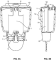
- FIG. 3a and 3b A further embodiment of a reservoir 5 is depicted in Figures 3a and 3b .
- the reservoir 5 comprises an applicator wick 1 having the shape of the embodiment of Figure 1a .
- the wick 1 is arranged in the interior of the reservoir 5 with two wick sections 3 extending through the dispensing outlets 7, while the protrusion 4 of the applicator wick 1 is fixed within the interior of the reservoir 5 by means of a retaining structure 9 of a lid 10 which is, e.g. permanently, attached to the end of the reservoir 5 facing away from the dispensing outlets 7.
- the lid 10 may be fixed at the reservoir 5 by means of ultrasonic welding in the region of a collar 11.
- the lid 10 may further be provided with a valve 12 for filling the reservoir 5.
- both dispensing outlets 7 is slightly larger than the cross section area of the wick sections 3 extending through the respective dispensing outlet 7, thereby forming the air vent (not shown).
- the dispensing outlets 7 may have a substantially rectangular orifice area corresponding to the outer shape of the wick sections 3 with an additional bulge forming the air vent.
- the reservoir 5 is provided with snap arms 13 for releasably attaching the reservoir 5 to a not shown skin treatment device.
- the reservoir 5 is arranged at a position of the skin treatment device permitting dispensing of the skin care product to a user's skin during use of the skin treatment device.
- the wick 1 is retained in the reservoir 5 interposed between the lid 10 and the side of the reservoir having the dispensing outlets 7. As can be seen, the cutout 2 of the wick 1 rests on a bridge portion 14 formed between the necks 6 with the dispensing outlets 7. With this arrangement unintended movement of the wick 1 within the reservoir 5 may be prevented.
- a lotion as a skin care product with a viscosity of 2,0 mPa s, a surface tension of 30 mN/m and a density of 1,01 g/cm 3 was applied to a paper strip for assessment of the volume flow rate.
- the same lotion was used with a reservoir 5 as depicted in Figures 3a and 3b using an applicator wick 1 of a standard felt pen material having a density of 130 mg/cm 3 and 200 mg/cm 3 as comparison.
- the volume flow rate was reproducibly in the range of 0,7 ⁇ l/cm 2 to 2,5 ⁇ l/cm 2 and, thus, in a range suitable for applying a skin care product when using a skin treatment device.
Landscapes
- Media Introduction/Drainage Providing Device (AREA)
Priority Applications (1)
| Application Number | Priority Date | Filing Date | Title |
|---|---|---|---|
| EP17191824.6A EP3456218A1 (de) | 2017-09-19 | 2017-09-19 | Hautbehandlungsvorrichtung und verwendung eines reservoirs mit einer hautbehandlungsvorrichtung |
Applications Claiming Priority (1)
| Application Number | Priority Date | Filing Date | Title |
|---|---|---|---|
| EP17191824.6A EP3456218A1 (de) | 2017-09-19 | 2017-09-19 | Hautbehandlungsvorrichtung und verwendung eines reservoirs mit einer hautbehandlungsvorrichtung |
Publications (1)
| Publication Number | Publication Date |
|---|---|
| EP3456218A1 true EP3456218A1 (de) | 2019-03-20 |
Family
ID=59968938
Family Applications (1)
| Application Number | Title | Priority Date | Filing Date |
|---|---|---|---|
| EP17191824.6A Withdrawn EP3456218A1 (de) | 2017-09-19 | 2017-09-19 | Hautbehandlungsvorrichtung und verwendung eines reservoirs mit einer hautbehandlungsvorrichtung |
Country Status (1)
| Country | Link |
|---|---|
| EP (1) | EP3456218A1 (de) |
Citations (4)
| Publication number | Priority date | Publication date | Assignee | Title |
|---|---|---|---|---|
| US3768161A (en) * | 1971-12-21 | 1973-10-30 | W Miller | Razor with lubricant dispenser |
| WO2006069744A1 (en) * | 2004-12-30 | 2006-07-06 | Unilever Plc | Applicator for liquid cosmetic compositions |
| US20080149133A1 (en) * | 2005-09-14 | 2008-06-26 | Ulrich Fleischer | Apparatus for Applying Liquid Agents to Hair on the Head |
| US20090178282A1 (en) | 2008-01-11 | 2009-07-16 | Gordon Gerald Guay | Hair Removal With Fluid Delivery |
-
2017
- 2017-09-19 EP EP17191824.6A patent/EP3456218A1/de not_active Withdrawn
Patent Citations (4)
| Publication number | Priority date | Publication date | Assignee | Title |
|---|---|---|---|---|
| US3768161A (en) * | 1971-12-21 | 1973-10-30 | W Miller | Razor with lubricant dispenser |
| WO2006069744A1 (en) * | 2004-12-30 | 2006-07-06 | Unilever Plc | Applicator for liquid cosmetic compositions |
| US20080149133A1 (en) * | 2005-09-14 | 2008-06-26 | Ulrich Fleischer | Apparatus for Applying Liquid Agents to Hair on the Head |
| US20090178282A1 (en) | 2008-01-11 | 2009-07-16 | Gordon Gerald Guay | Hair Removal With Fluid Delivery |
Similar Documents
| Publication | Publication Date | Title |
|---|---|---|
| JP4286023B2 (ja) | 物質を皮膚に塗布するよう構成されたアプリケータエレメントを有するアプリケータ | |
| US20040177510A1 (en) | Apparatus and method for dispensing a shaving aid onto a user's skin during a shaving operation | |
| US5636931A (en) | Applicator device with a perforated piston | |
| US7134799B2 (en) | Applicator including an applicator element for applying a substance, in particular a cosmetic or another care product | |
| JPH08275820A (ja) | 端部スリットを有する毛管式施与装置 | |
| US20060272154A1 (en) | Disposable gel-dispensing razor | |
| KR101969739B1 (ko) | 사용자의 입술 상에 화장품을 도포하기 위한 도포기 및 관련된 도포 방법 | |
| KR20100101651A (ko) | 유체 전달을 수반하는 모발 제거 | |
| US7841793B2 (en) | Device for packaging and applying a cosmetic product | |
| JP2002125752A (ja) | 2つの組み合わされた部品及びフロック加工被覆を有するディスペンサ端部部品 | |
| EP3458163B1 (de) | Vorrichtung zur getrennten abgabe von materialien zur gemeinsamen verwendung auf der menschlichen haut | |
| JP6005744B2 (ja) | 回転アプリケータを有する、化粧品を塗布するためのデバイス | |
| KR101808284B1 (ko) | 탈착식 어플리케이터부가 구비된 튜브용기 | |
| US20160157580A1 (en) | Deodorant dispenser and refill cartridge therefor | |
| JP2005246051A (ja) | 製品の塗布装置 | |
| US10117497B1 (en) | Liquid dermatological agent dispensing device | |
| US10702040B2 (en) | Liquid dermatological agent dispensing device | |
| KR101995648B1 (ko) | 아이 라이너를 포장 및 도포하기 위한 디바이스 | |
| US6666216B2 (en) | Device for applying a product to a surface | |
| EP3456218A1 (de) | Hautbehandlungsvorrichtung und verwendung eines reservoirs mit einer hautbehandlungsvorrichtung | |
| JP2007093198A (ja) | 冷却デバイスならびにこの冷却デバイスを備えたアセンブリ | |
| JP2022508186A (ja) | 化粧品組成物を調製するためのデバイスおよび関連する調製プロセス | |
| JP2012101395A (ja) | 塗布具 | |
| US10392170B2 (en) | Container cap | |
| EP3207821B1 (de) | Haarfärbemittelapplikator |
Legal Events
| Date | Code | Title | Description |
|---|---|---|---|
| PUAI | Public reference made under article 153(3) epc to a published international application that has entered the european phase |
Free format text: ORIGINAL CODE: 0009012 |
|
| AK | Designated contracting states |
Kind code of ref document: A1 Designated state(s): AL AT BE BG CH CY CZ DE DK EE ES FI FR GB GR HR HU IE IS IT LI LT LU LV MC MK MT NL NO PL PT RO RS SE SI SK SM TR |
|
| AX | Request for extension of the european patent |
Extension state: BA ME |
|
| STAA | Information on the status of an ep patent application or granted ep patent |
Free format text: STATUS: THE APPLICATION HAS BEEN WITHDRAWN |
|
| 18W | Application withdrawn |
Effective date: 20190430 |