EP3456257B1 - Procédé d'interprétation des rapports signal/bruit détectés dans un réseau de capteurs d'électrodes en termes d'état cognitif - Google Patents
Procédé d'interprétation des rapports signal/bruit détectés dans un réseau de capteurs d'électrodes en termes d'état cognitif Download PDFInfo
- Publication number
- EP3456257B1 EP3456257B1 EP18192334.3A EP18192334A EP3456257B1 EP 3456257 B1 EP3456257 B1 EP 3456257B1 EP 18192334 A EP18192334 A EP 18192334A EP 3456257 B1 EP3456257 B1 EP 3456257B1
- Authority
- EP
- European Patent Office
- Prior art keywords
- signal
- ecg
- individual
- noise ratio
- sensors
- Prior art date
- Legal status (The legal status is an assumption and is not a legal conclusion. Google has not performed a legal analysis and makes no representation as to the accuracy of the status listed.)
- Active
Links
Images




Classifications
-
- A—HUMAN NECESSITIES
- A61—MEDICAL OR VETERINARY SCIENCE; HYGIENE
- A61B—DIAGNOSIS; SURGERY; IDENTIFICATION
- A61B5/00—Measuring for diagnostic purposes; Identification of persons
- A61B5/24—Detecting, measuring or recording bioelectric or biomagnetic signals of the body or parts thereof
- A61B5/316—Modalities, i.e. specific diagnostic methods
- A61B5/318—Heart-related electrical modalities, e.g. electrocardiography [ECG]
-
- A—HUMAN NECESSITIES
- A61—MEDICAL OR VETERINARY SCIENCE; HYGIENE
- A61B—DIAGNOSIS; SURGERY; IDENTIFICATION
- A61B5/00—Measuring for diagnostic purposes; Identification of persons
- A61B5/16—Devices for psychotechnics; Testing reaction times ; Devices for evaluating the psychological state
- A61B5/18—Devices for psychotechnics; Testing reaction times ; Devices for evaluating the psychological state for vehicle drivers or machine operators
-
- A—HUMAN NECESSITIES
- A61—MEDICAL OR VETERINARY SCIENCE; HYGIENE
- A61B—DIAGNOSIS; SURGERY; IDENTIFICATION
- A61B5/00—Measuring for diagnostic purposes; Identification of persons
- A61B5/24—Detecting, measuring or recording bioelectric or biomagnetic signals of the body or parts thereof
- A61B5/25—Bioelectric electrodes therefor
- A61B5/279—Bioelectric electrodes therefor specially adapted for particular uses
- A61B5/28—Bioelectric electrodes therefor specially adapted for particular uses for electrocardiography [ECG]
- A61B5/282—Holders for multiple electrodes
-
- A—HUMAN NECESSITIES
- A61—MEDICAL OR VETERINARY SCIENCE; HYGIENE
- A61B—DIAGNOSIS; SURGERY; IDENTIFICATION
- A61B5/00—Measuring for diagnostic purposes; Identification of persons
- A61B5/24—Detecting, measuring or recording bioelectric or biomagnetic signals of the body or parts thereof
- A61B5/316—Modalities, i.e. specific diagnostic methods
- A61B5/318—Heart-related electrical modalities, e.g. electrocardiography [ECG]
- A61B5/346—Analysis of electrocardiograms
- A61B5/349—Detecting specific parameters of the electrocardiograph cycle
- A61B5/364—Detecting abnormal ECG interval, e.g. extrasystoles, ectopic heartbeats
-
- A—HUMAN NECESSITIES
- A61—MEDICAL OR VETERINARY SCIENCE; HYGIENE
- A61B—DIAGNOSIS; SURGERY; IDENTIFICATION
- A61B5/00—Measuring for diagnostic purposes; Identification of persons
- A61B5/72—Signal processing specially adapted for physiological signals or for diagnostic purposes
- A61B5/7203—Signal processing specially adapted for physiological signals or for diagnostic purposes for noise prevention, reduction or removal
- A61B5/7207—Signal processing specially adapted for physiological signals or for diagnostic purposes for noise prevention, reduction or removal of noise induced by motion artifacts
-
- A—HUMAN NECESSITIES
- A61—MEDICAL OR VETERINARY SCIENCE; HYGIENE
- A61B—DIAGNOSIS; SURGERY; IDENTIFICATION
- A61B5/00—Measuring for diagnostic purposes; Identification of persons
- A61B5/72—Signal processing specially adapted for physiological signals or for diagnostic purposes
- A61B5/7221—Determining signal validity, reliability or quality
-
- A—HUMAN NECESSITIES
- A61—MEDICAL OR VETERINARY SCIENCE; HYGIENE
- A61B—DIAGNOSIS; SURGERY; IDENTIFICATION
- A61B5/00—Measuring for diagnostic purposes; Identification of persons
- A61B5/72—Signal processing specially adapted for physiological signals or for diagnostic purposes
- A61B5/7271—Specific aspects of physiological measurement analysis
-
- A—HUMAN NECESSITIES
- A61—MEDICAL OR VETERINARY SCIENCE; HYGIENE
- A61B—DIAGNOSIS; SURGERY; IDENTIFICATION
- A61B2562/00—Details of sensors; Constructional details of sensor housings or probes; Accessories for sensors
- A61B2562/04—Arrangements of multiple sensors of the same type
- A61B2562/046—Arrangements of multiple sensors of the same type in a matrix array
Definitions
- the present invention generally relates to biological parameters monitoring, and more particularly relates to a method for measuring the cognitive state of an individual.
- EP2783725A1 discloses an object, a method and a system for detecting heartbeat or whether an electrode is in good contact.
- the heartbeat is detected by arranging multiple textile electrodes on the textile, using ECG equipotential line diagram, considering interference caused of human movement, and designing a separating electrode structure, electrode position, area and lead layout in an innovative manner; the dry electrode or capacitive coupling electrode is selected along with the change of environmental state so as to pick up the ECG signals; the contact between the electrode and the human body can be detected whether it is in a good state or not by measuring the noise, body surface impedance, muscle impedance and the like; in addition, the posture and action of human body can be speculated according to the wave mode and noise of the ECG signals.
- a method is provided for measuring the cognitive state of an individual as defined in claim 1.
- a system for measuring the cognitive state of an individual.
- the system comprises: an array of electrocardiogram (ECG) sensors placed in contact with the individual, where the ECG sensors continually measuring the ECG voltage and related signal-to-noise ratio for each ECG sensor of the array; and a microprocessor that receives the signal-to-noise ratio from each ECG sensor, where the microprocessor, calculates a distance to each ECG sensor and pressure applied to each ECG sensor that corresponds to the ECG voltage and signal-to-noise ratio measurements, generates a graphical distance and pressure map based on the combined signal-to-noise ratios of the ECG sensors, and continually analyzes the distance and pressure map to determine the cognitive state of the individual.
- ECG electrocardiogram
- a system and method for measuring the cognitive state of an individual has been developed.
- One embodiment involves placing an array of capacitive electrocardiogram (ECG) sensors in indirect contact with a subject individual.
- ECG capacitive electrocardiogram
- the sensors continually measure the ECG voltage and determine the related signal-to-noise ratio for each sensor with the sensor hardware.
- Distance and pressure is calculated for each ECG sensor that corresponds to readout of the ECG voltage and its signal-to-noise ratio.
- Distance and pressure values that are calculated for each sensor of the array are used to generate a graphical distance and pressure map that is continually analyzed to determine the cognitive state of the individual.
- FIG. 1 a diagram 100 is shown of an array of electrocardiogram (ECG) sensors in contact with a subject individual 104 in accordance with one embodiment.
- ECG electrocardiogram
- a 3 x 3 square grid of ECG sensors 102 is shown.
- the array of ECG sensors could be arranged in a rectangular or similar shaped grid pattern of sensors. Additionally, the grid pattern could be longer in the horizontal direction with a greater number of sensors in each horizontal row. This embodiment would have the advantage of providing more sensors in contact with the chest area of the subject individual 104.
- the array collectively measures EC voltage and signal-to-noise ratio from each sensor recorded on the individual.
- the contact with the skin of the individual is in direct because an ECG sensor may function with up to 1 centimeter (cm) of insulation between the individual and the sensor. This will account for any padding on the seat or clothing worn by the subject individual.
- the sensors may be placed in direct physical contact with the individual.
- a signal-to-noise ratio is determined by the hardware of each ECG sensor 106 as the strength of the signal divided by electronic background noise.
- the sensor in the lower right-hand corner of the grid (E 33) is shown to have a relative signal strength of 10 with a relative noise strength of 1 for a signal-to-noise ratio of 10. This is the highest signal-to-noise ratio in the grid sensors and it reflects the strongest signal of the array.
- the strength of the signal is proportional to the distance between the individual and the sensor and to pressure applied on this sensor by the subject individual. Both distance and pressure are calculated for each sensor of the array.
- FIG. 2 a signal-to-noise ratio map 200 is shown of an ECG array in accordance with a prior art embodiment.
- the signal-to-noise ratio would merely identify E 33 sensor 202 as having the highest signal-to-noise ratio in the array.
- the signal from E 33 would be used to provide the most reliable ECG voltage of all sensors of the array while the signals from the other sensors in the array would be ignored.
- FIG. 3 shows a signal-to-noise ratio map 300 of an ECG array in accordance with a present embodiment.
- the signal-to-noise ratios 302 of each sensor are measured and reflected on the signal-to-noise ratio map with respect to quality of the contact.
- color coding is used to indicate the relative value of the signal-to-noise ratios.
- the signal-to-noise ratio map can provide a more complete mapping of the distance and pressure being applied on the sensor array. The map may then be used to determine the direction and extent of movement by the subject individual as an independent quantity together with the ECG voltage.
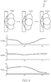
- FIG. 4 a series of inputs to vertical columns of ECG sensors are shown in comparison to graphs of the output signal-to-noise ratios from those columns of sensors.
- an overhead view is shown of a subject individual 402a, 402b and 402c in different positions while in contact with the left (L), center (C) and right (R) columns of the sensor array.
- Graphs of the signal-to-noise output for each column 404a, 404b and 404c are shown below the corresponding position of the subject individual.
- the signal-to-noise ratio on all columns of sensors is steady 404a, 404b, and 404c.
- the signal-to-noise ratio increases 402c. Meanwhile, the signal-to-noise ratio decreases on the left side as the pressure decreases 404a. Conversely, as a subject individual shifts to the left side of the array and increases pressure there 402c, the signal-to-noise ratio increases on the left side column of sensors 404a. The signal-to-noise ratio decreases on the right side column of sensors as the pressure decreases 404c. It should be understood, that similar signal to noise ratio patterns can be achieved with other types of movement by the subject individual such as bending forward to increase the pressure on the bottom rows of the array and leaning back to increase pressure on the top rows of the array.
- FIG. 5 a series of signal-to-noise ratio maps 500 are shown in comparison to the position of the subject individual.
- a signal-to-noise ratio map 502a representing the distance and pressure of the individual shifting to the right 504a is shown with a pattern that reflects higher signal-to-noise ratios on the right side of the array.
- a signal-to-noise ratio map 502c representing the distance and pressure of the individual shifting to the left 504c is shown with a pattern reflecting higher signal-to-noise ratios on the left side of the array.
- the signal-to-noise ratio map 502b shows a broad signal-to-noise ratio across the center of the array.
- the distance and pressure maps of the ECG signal-to-noise ratios may be used to measure the movement, posture, breathing pattern and pulse rate of the individual.
- the pulse rate of the subject intimate visual may be determined by measuring the delay between the "R-peak” and blood pressure (BP) wave of the signal of the ECG sensors.
- FIG. 6 graphs of the ECG sensor signal-to-noise ratios 600 that correspond to different cognitive states of the subject individual are shown. These graphs 602a, 602b and 602c show signal-to-noise ratio outputs over the period of one minute.
- the first graph 602a shows high amplitude with repeated irregular patterns. This reflects wiggling by the subject individual and is one of the symptoms of fatigue, drowsiness or stress. If this is detected, an alarm may be sent to alert the individual.
- the second graph 602b shows low amplitude irregular patterns which are typical for small-scale body movements during low activity. This pattern indicates no fatigue and no alarm should be sent.
- the third graph 602c shows slow, high amplitude drift which reflects large-scale deliberate body movements during more demanding activity. This pattern also indicates no fatigue and no alarm should be sent.
- FIG. 7 a flowchart is shown of a method of determining the cognitive state of the individual using signal-to-noise ratios from an ECG array 700.
- the ECG array is placed in contact with the subject individual 702.
- the ECG sensors in the array are used to measure the ECG voltage and to generate a signal-to-noise ratio for each individual sensor 706.
- the signal-to-noise ratios are collectively used to create a distance and pressure signal map 708.
- the signal map is analyzed to determine the subject's cognitive state 710. The analysis continues as long as the subject is in contact with the sensor array 712.
- this method may be used to monitor the cognitive state of aircraft flight crew, vehicle drivers, plant operators or any job requiring alertness of the subject individual.
- Skilled artisans may implement the described functionality in varying ways for each particular application, but such implementation decisions should not be interpreted as causing a departure from the scope of the present invention.
- an embodiment of a system or a component may employ various integrated circuit components, e.g., memory elements, digital signal processing elements, logic elements, look-up tables, or the like, which may carry out a variety of functions under the control of one or more microprocessors or other control devices.
- integrated circuit components e.g., memory elements, digital signal processing elements, logic elements, look-up tables, or the like, which may carry out a variety of functions under the control of one or more microprocessors or other control devices.
- DSP digital signal processor
- ASIC application specific integrated circuit
- FPGA field programmable gate array
- a general-purpose processor may be a microprocessor, but in the alternative, the processor may be any conventional processor, controller, microcontroller, or state machine.
- a processor may also be implemented as a combination of computing devices, e.g., a combination of a DSP and a microprocessor, a plurality of microprocessors, one or more microprocessors in conjunction with a DSP core, or any other such configuration.
- a software module may reside in RAM memory, flash memory, ROM memory, EPROM memory, EEPROM memory, registers, hard disk, a removable disk, a CD-ROM, or any other form of storage medium known in the art.
- An exemplary storage medium is coupled to the processor such that the processor can read information from, and write information to, the storage medium.
- the storage medium may be integral to the processor.
- the processor and the storage medium may reside in an ASIC.
- the ASIC may reside in a user terminal.
- the processor and the storage medium may reside as discrete components in a user terminal
Landscapes
- Health & Medical Sciences (AREA)
- Life Sciences & Earth Sciences (AREA)
- Engineering & Computer Science (AREA)
- Public Health (AREA)
- Biophysics (AREA)
- Pathology (AREA)
- Physics & Mathematics (AREA)
- Biomedical Technology (AREA)
- Heart & Thoracic Surgery (AREA)
- Medical Informatics (AREA)
- Molecular Biology (AREA)
- Surgery (AREA)
- Animal Behavior & Ethology (AREA)
- General Health & Medical Sciences (AREA)
- Veterinary Medicine (AREA)
- Cardiology (AREA)
- Signal Processing (AREA)
- Psychiatry (AREA)
- Artificial Intelligence (AREA)
- Computer Vision & Pattern Recognition (AREA)
- Physiology (AREA)
- Child & Adolescent Psychology (AREA)
- Developmental Disabilities (AREA)
- Educational Technology (AREA)
- Hospice & Palliative Care (AREA)
- Psychology (AREA)
- Social Psychology (AREA)
- Measurement And Recording Of Electrical Phenomena And Electrical Characteristics Of The Living Body (AREA)
Claims (10)
- Procédé de mesure de l'état cognitif d'une personne, comprenant :le placement d'un réseau de capteurs d'électrocardiogramme (ECG) (102) en contact avec la personne (104) ;la mesure en continu du rapport signal/bruit (302) pour chaque capteur d'ECG (106) ;le calcul d'une distance et d'une pression entre la personne (104) et chaque capteur d'ECG (106) qui correspond au rapport signal/bruit (302) pour chaque capteur d'ECG (106) respectif ;la génération d'une carte de rapport signal/bruit (502a) sur la base des rapports signal/bruit (302) des capteurs d'ECG (106), la carte de rapport signal/bruit (502a) utilisant un codage couleur pour indiquer la valeur relative des rapports signal/bruit (302) ; etl'analyse en continu de la carte de rapport signal/bruit (502a) pour détecter une amplitude élevée et des motifs irréguliers répétés qui indiquent un état cognitif de fatigue de la personne (104).
- Procédé selon la revendication 1, le réseau de capteurs d'ECG (102) comprenant un motif de capteurs (106) en grille de forme rectangulaire.
- Procédé selon la revendication 1, la distance et la pression calculées sur chaque capteur d'ECG (106) correspondant au mouvement de la personne (104).
- Procédé selon la revendication 1, la distance et la pression calculées sur chaque capteur d'ECG (106) correspondant à la posture de la personne (104).
- Procédé selon la revendication 1, la distance et la pression calculées sur chaque capteur d'ECG (106) correspondant à un motif respiratoire de la personne (104).
- Procédé selon la revendication 1, la distance et la pression calculées sur chaque capteur d'ECG (106) correspondant à une fréquence du pouls de la personne (104).
- Procédé selon la revendication 6, la fréquence du pouls de la personne (104) étant déterminée à partir du retard entre le pic R et l'onde de pression artérielle (PA) du signal d'ECG.
- Procédé selon la revendication 1, dans lequel la carte de rapport signal/bruit (502a) est générée sur la base d'amplitudes des rapports signal/bruit (302) des capteurs d'ECG (106).
- Procédé selon la revendication 1, la carte de rapport signal/bruit (502a) étant générée sur la base de la périodicité et de descripteurs chaotiques des rapports signal/bruit (302) des capteurs d'ECG (106).
- Procédé selon la revendication 1, la carte de rapport signal/bruit (502a) étant générée sur la base d'une vitesse d'apparition et d'un déclin des rapports signal/bruit (302) des capteurs d'ECG (106).
Applications Claiming Priority (1)
| Application Number | Priority Date | Filing Date | Title |
|---|---|---|---|
| US15/708,945 US10499827B2 (en) | 2017-09-19 | 2017-09-19 | System and method for interpretation of signal-to-noise ratios detected in an array of electrodes sensors in terms of physical and cognitive state |
Publications (2)
| Publication Number | Publication Date |
|---|---|
| EP3456257A1 EP3456257A1 (fr) | 2019-03-20 |
| EP3456257B1 true EP3456257B1 (fr) | 2021-09-01 |
Family
ID=63667682
Family Applications (1)
| Application Number | Title | Priority Date | Filing Date |
|---|---|---|---|
| EP18192334.3A Active EP3456257B1 (fr) | 2017-09-19 | 2018-09-04 | Procédé d'interprétation des rapports signal/bruit détectés dans un réseau de capteurs d'électrodes en termes d'état cognitif |
Country Status (3)
| Country | Link |
|---|---|
| US (1) | US10499827B2 (fr) |
| EP (1) | EP3456257B1 (fr) |
| CN (1) | CN109512421B (fr) |
Families Citing this family (1)
| Publication number | Priority date | Publication date | Assignee | Title |
|---|---|---|---|---|
| US20220405518A1 (en) * | 2021-06-18 | 2022-12-22 | Honeywell International Inc. | System for sensing an operator's capacitive state |
Family Cites Families (33)
| Publication number | Priority date | Publication date | Assignee | Title |
|---|---|---|---|---|
| WO1998002090A1 (fr) | 1996-07-17 | 1998-01-22 | Cambridge Heart, Inc. | Generation de mesures cardiaques localisees |
| US7485095B2 (en) * | 2000-05-30 | 2009-02-03 | Vladimir Shusterman | Measurement and analysis of trends in physiological and/or health data |
| EP2319410A1 (fr) * | 2003-09-12 | 2011-05-11 | BodyMedia, Inc. | Appareil pour la mesure de paramètres cardiaques |
| US7396331B2 (en) * | 2003-10-27 | 2008-07-08 | Home Guardian, Llc | System and process for non-invasive collection and analysis of physiological signals |
| US20060041196A1 (en) | 2004-08-17 | 2006-02-23 | Quasar, Inc. | Unobtrusive measurement system for bioelectric signals |
| AU2004324705A1 (en) * | 2004-11-08 | 2006-05-11 | Idesia Ltd. | Method and apparatus for electro-biometric indentity recognition |
| WO2006109072A2 (fr) * | 2005-04-14 | 2006-10-19 | Hidalgo Limited | Appareil et systeme de surveillance |
| US9101264B2 (en) * | 2006-06-15 | 2015-08-11 | Peerbridge Health, Inc. | Wireless electrode arrangement and method for patient monitoring via electrocardiography |
| US8214007B2 (en) * | 2006-11-01 | 2012-07-03 | Welch Allyn, Inc. | Body worn physiological sensor device having a disposable electrode module |
| US8602997B2 (en) * | 2007-06-12 | 2013-12-10 | Sotera Wireless, Inc. | Body-worn system for measuring continuous non-invasive blood pressure (cNIBP) |
| US8396537B2 (en) * | 2009-04-20 | 2013-03-12 | Mindray Ds Usa, Inc. | Method and system to measure ECG and respiration |
| US20140249432A1 (en) * | 2010-12-28 | 2014-09-04 | Matt Banet | Body-worn system for continuous, noninvasive measurement of cardiac output, stroke volume, cardiac power, and blood pressure |
| US9629566B2 (en) * | 2011-03-11 | 2017-04-25 | Spacelabs Healthcare Llc | Methods and systems to determine multi-parameter managed alarm hierarchy during patient monitoring |
| US20120265080A1 (en) | 2011-04-15 | 2012-10-18 | Xiong Yu | Non-contact sensing of physiological signals |
| WO2013075270A1 (fr) | 2011-11-25 | 2013-05-30 | Yang Chang-Ming | Objet, procédé, et système servant à détecter un battement de cœur ou à déterminer si des électrodes sont en contact correct |
| KR101316497B1 (ko) * | 2012-08-03 | 2013-10-10 | 현대자동차주식회사 | 승객의 심박수 관찰시스템 및 관찰방법 |
| JP2016509868A (ja) * | 2013-02-13 | 2016-04-04 | ルマン・ミクロ・デバイシズ・ソシエテ・アノニムLeman Micro Devices Sa | 非侵襲的血液分析 |
| AU2014232694A1 (en) * | 2013-03-15 | 2015-09-17 | Peerbridge Health, Inc. | System and method for monitoring and diagnosing patient condition based on wireless sensor monitoring data |
| US8874301B1 (en) | 2013-07-09 | 2014-10-28 | Ford Global Technologies, Llc | Autonomous vehicle with driver presence and physiological monitoring |
| DE102013219513A1 (de) * | 2013-09-27 | 2015-04-02 | Ford Global Technologies, Llc | Sensor zur berührungslosen elektrokardiographischen Messung, Sensorarray und Sitz oder Liege |
| JP6711750B2 (ja) * | 2013-11-22 | 2020-06-17 | エムシー10 インコーポレイテッドMc10,Inc. | 心臓活動の検知および分析のためのコンフォーマルセンサシステム |
| US9554724B2 (en) * | 2013-12-11 | 2017-01-31 | Samsung Electronics Co., Ltd. | Self-aligning sensor array |
| CN104706343A (zh) * | 2013-12-11 | 2015-06-17 | 三星电子株式会社 | 用于心率检测的生物阻抗传感器阵列 |
| CA2931274A1 (fr) * | 2014-01-21 | 2015-07-30 | California Institute Of Technology | Systemes de capteur d'etat hemodynamique electronique portatifs |
| JP6539827B2 (ja) * | 2014-01-27 | 2019-07-10 | リズム ダイアグノスティック システムズ,インク. | 生理パラメータをモニタリングするデバイス |
| US10258288B2 (en) * | 2014-03-24 | 2019-04-16 | Samsung Electronics Co., Ltd. | Confidence indicator for physiological measurements using a wearable sensor platform |
| BR112016030185A2 (pt) | 2014-09-23 | 2021-09-08 | Rr Sequences Inc | Módulo de processamento digital (dpm), sistema e método para prover sinais de eletrocardiograma (ecg) para um corpo humano |
| US9848825B2 (en) * | 2014-09-29 | 2017-12-26 | Microsoft Technology Licensing, Llc | Wearable sensing band |
| WO2016125214A1 (fr) | 2015-02-06 | 2016-08-11 | パナソニックIpマネジメント株式会社 | Dispositif et procédé d'acquisition de signal biologique |
| KR20160147516A (ko) * | 2015-06-15 | 2016-12-23 | 삼성전자주식회사 | 부정맥을 검출하기 위한 방법 및 이를 지원하는 장치 |
| CN105260864B (zh) * | 2015-09-17 | 2019-03-29 | 浙江万里学院 | 基于频谱感知的云物流监控系统及监控方法 |
| CN106255066B (zh) * | 2016-09-23 | 2019-06-25 | 宁波大学 | 协同认知无线网络多用户通信动态判决方法 |
| CN107102305B (zh) * | 2017-02-24 | 2020-08-11 | 电子科技大学 | 一种杂波环境下稳健的认知雷达发射接收联合设计方法 |
-
2017
- 2017-09-19 US US15/708,945 patent/US10499827B2/en active Active
-
2018
- 2018-09-04 EP EP18192334.3A patent/EP3456257B1/fr active Active
- 2018-09-18 CN CN201811086510.XA patent/CN109512421B/zh active Active
Non-Patent Citations (1)
| Title |
|---|
| BIN HE ET AL: "A high resolution cardiac mapping system", PROCEEDINGS OF THE ANNUAL INTERNATIONAL CONFERENCE OF THE IEEE ENGINEERING IN MEDICINE AND BIOLOGY SOCIETY : PARIS, FRANCE, OCTOBER 29 - NOVEMBER 1, 1992, IEEE, NEW YORK, NY, USA, 29 October 1992 (1992-10-29), pages 812 - 814, XP031861787, ISBN: 978-0-7803-0785-8, DOI: 10.1109/IEMBS.1992.5761252 * |
Also Published As
| Publication number | Publication date |
|---|---|
| US10499827B2 (en) | 2019-12-10 |
| CN109512421B (zh) | 2023-08-04 |
| US20190082986A1 (en) | 2019-03-21 |
| CN109512421A (zh) | 2019-03-26 |
| EP3456257A1 (fr) | 2019-03-20 |
Similar Documents
| Publication | Publication Date | Title |
|---|---|---|
| JP6435104B2 (ja) | 身体状態の変化を判定するシステム及び方法 | |
| Tayel et al. | Poincaré plot for heart rate variability | |
| Jung et al. | Driver fatigue and drowsiness monitoring system with embedded electrocardiogram sensor on steering wheel | |
| CN103815896B (zh) | 一种精神疲劳监测方法、装置、系统及移动处理终端 | |
| JP5872559B2 (ja) | 被験者の呼吸活動をモニタする方法と装置 | |
| EP3485806A1 (fr) | Dispositif portable capable de détecter un événement d'apnée du sommeil | |
| JP2014180543A5 (fr) | ||
| JP2008264138A (ja) | 睡眠状態判定装置、睡眠状態判定方法及びコンピュータプログラム | |
| JP2007061439A (ja) | 生体情報測定装置および生体情報計測方法 | |
| CN107997754B (zh) | 一种智能床垫系统及人体生理特征数据提取方法 | |
| KR20200010145A (ko) | 심전도 기반 모션 제어 장치 | |
| EP4104759A1 (fr) | Système de détection de l'état psychophysiologique d'un opérateur | |
| US20170367655A1 (en) | State determination system | |
| US10499827B2 (en) | System and method for interpretation of signal-to-noise ratios detected in an array of electrodes sensors in terms of physical and cognitive state | |
| US12605102B2 (en) | Biological signal processing device, watching system, and watching method | |
| US10512434B2 (en) | Brain activity measurement device, program, and method | |
| JP5846179B2 (ja) | 生体情報取得装置 | |
| JP5785791B2 (ja) | 入眠状態判定装置 | |
| KR102718009B1 (ko) | 심박수 측정 장치 및 방법 | |
| Rawal et al. | Adaptive correlation dimension method for analysing heart rate variability during the menstrual cycle | |
| JP7458170B2 (ja) | 学習装置、学習方法、および測定装置 | |
| WO2017169993A1 (fr) | Distribution de pression corporelle et dispositif de mesure d'informations biométriques | |
| CN106175735A (zh) | 无创血压检测装置、方法及穿戴式电子装置 | |
| JP2015066319A (ja) | 生体情報取得装置 | |
| TWI744017B (zh) | 疲勞分析方法 |
Legal Events
| Date | Code | Title | Description |
|---|---|---|---|
| PUAI | Public reference made under article 153(3) epc to a published international application that has entered the european phase |
Free format text: ORIGINAL CODE: 0009012 |
|
| STAA | Information on the status of an ep patent application or granted ep patent |
Free format text: STATUS: REQUEST FOR EXAMINATION WAS MADE |
|
| 17P | Request for examination filed |
Effective date: 20180904 |
|
| AK | Designated contracting states |
Kind code of ref document: A1 Designated state(s): AL AT BE BG CH CY CZ DE DK EE ES FI FR GB GR HR HU IE IS IT LI LT LU LV MC MK MT NL NO PL PT RO RS SE SI SK SM TR |
|
| AX | Request for extension of the european patent |
Extension state: BA ME |
|
| STAA | Information on the status of an ep patent application or granted ep patent |
Free format text: STATUS: EXAMINATION IS IN PROGRESS |
|
| 17Q | First examination report despatched |
Effective date: 20201020 |
|
| REG | Reference to a national code |
Ref country code: DE Ref legal event code: R079 Ref document number: 602018022709 Country of ref document: DE Free format text: PREVIOUS MAIN CLASS: A61B0005040800 Ipc: A61B0005282000 |
|
| GRAP | Despatch of communication of intention to grant a patent |
Free format text: ORIGINAL CODE: EPIDOSNIGR1 |
|
| STAA | Information on the status of an ep patent application or granted ep patent |
Free format text: STATUS: GRANT OF PATENT IS INTENDED |
|
| RIC1 | Information provided on ipc code assigned before grant |
Ipc: A61B 5/18 20060101ALI20210517BHEP Ipc: A61B 5/00 20060101ALI20210517BHEP Ipc: A61B 5/339 20210101ALI20210517BHEP Ipc: A61B 5/282 20210101AFI20210517BHEP |
|
| INTG | Intention to grant announced |
Effective date: 20210614 |
|
| RIN1 | Information on inventor provided before grant (corrected) |
Inventor name: MALY, LUKAS Inventor name: KUNES, DAVID Inventor name: MORAVEK, ZDENEK |
|
| GRAS | Grant fee paid |
Free format text: ORIGINAL CODE: EPIDOSNIGR3 |
|
| GRAA | (expected) grant |
Free format text: ORIGINAL CODE: 0009210 |
|
| STAA | Information on the status of an ep patent application or granted ep patent |
Free format text: STATUS: THE PATENT HAS BEEN GRANTED |
|
| AK | Designated contracting states |
Kind code of ref document: B1 Designated state(s): AL AT BE BG CH CY CZ DE DK EE ES FI FR GB GR HR HU IE IS IT LI LT LU LV MC MK MT NL NO PL PT RO RS SE SI SK SM TR |
|
| REG | Reference to a national code |
Ref country code: GB Ref legal event code: FG4D |
|
| REG | Reference to a national code |
Ref country code: CH Ref legal event code: EP Ref country code: AT Ref legal event code: REF Ref document number: 1425346 Country of ref document: AT Kind code of ref document: T Effective date: 20210915 |
|
| REG | Reference to a national code |
Ref country code: DE Ref legal event code: R096 Ref document number: 602018022709 Country of ref document: DE |
|
| REG | Reference to a national code |
Ref country code: IE Ref legal event code: FG4D |
|
| REG | Reference to a national code |
Ref country code: LT Ref legal event code: MG9D |
|
| REG | Reference to a national code |
Ref country code: NL Ref legal event code: MP Effective date: 20210901 |
|
| PG25 | Lapsed in a contracting state [announced via postgrant information from national office to epo] |
Ref country code: RS Free format text: LAPSE BECAUSE OF FAILURE TO SUBMIT A TRANSLATION OF THE DESCRIPTION OR TO PAY THE FEE WITHIN THE PRESCRIBED TIME-LIMIT Effective date: 20210901 Ref country code: SE Free format text: LAPSE BECAUSE OF FAILURE TO SUBMIT A TRANSLATION OF THE DESCRIPTION OR TO PAY THE FEE WITHIN THE PRESCRIBED TIME-LIMIT Effective date: 20210901 Ref country code: HR Free format text: LAPSE BECAUSE OF FAILURE TO SUBMIT A TRANSLATION OF THE DESCRIPTION OR TO PAY THE FEE WITHIN THE PRESCRIBED TIME-LIMIT Effective date: 20210901 Ref country code: FI Free format text: LAPSE BECAUSE OF FAILURE TO SUBMIT A TRANSLATION OF THE DESCRIPTION OR TO PAY THE FEE WITHIN THE PRESCRIBED TIME-LIMIT Effective date: 20210901 Ref country code: ES Free format text: LAPSE BECAUSE OF FAILURE TO SUBMIT A TRANSLATION OF THE DESCRIPTION OR TO PAY THE FEE WITHIN THE PRESCRIBED TIME-LIMIT Effective date: 20210901 Ref country code: LT Free format text: LAPSE BECAUSE OF FAILURE TO SUBMIT A TRANSLATION OF THE DESCRIPTION OR TO PAY THE FEE WITHIN THE PRESCRIBED TIME-LIMIT Effective date: 20210901 Ref country code: BG Free format text: LAPSE BECAUSE OF FAILURE TO SUBMIT A TRANSLATION OF THE DESCRIPTION OR TO PAY THE FEE WITHIN THE PRESCRIBED TIME-LIMIT Effective date: 20211201 Ref country code: NO Free format text: LAPSE BECAUSE OF FAILURE TO SUBMIT A TRANSLATION OF THE DESCRIPTION OR TO PAY THE FEE WITHIN THE PRESCRIBED TIME-LIMIT Effective date: 20211201 |
|
| REG | Reference to a national code |
Ref country code: AT Ref legal event code: MK05 Ref document number: 1425346 Country of ref document: AT Kind code of ref document: T Effective date: 20210901 |
|
| PG25 | Lapsed in a contracting state [announced via postgrant information from national office to epo] |
Ref country code: PL Free format text: LAPSE BECAUSE OF FAILURE TO SUBMIT A TRANSLATION OF THE DESCRIPTION OR TO PAY THE FEE WITHIN THE PRESCRIBED TIME-LIMIT Effective date: 20210901 Ref country code: LV Free format text: LAPSE BECAUSE OF FAILURE TO SUBMIT A TRANSLATION OF THE DESCRIPTION OR TO PAY THE FEE WITHIN THE PRESCRIBED TIME-LIMIT Effective date: 20210901 Ref country code: GR Free format text: LAPSE BECAUSE OF FAILURE TO SUBMIT A TRANSLATION OF THE DESCRIPTION OR TO PAY THE FEE WITHIN THE PRESCRIBED TIME-LIMIT Effective date: 20211202 |
|
| PG25 | Lapsed in a contracting state [announced via postgrant information from national office to epo] |
Ref country code: AT Free format text: LAPSE BECAUSE OF FAILURE TO SUBMIT A TRANSLATION OF THE DESCRIPTION OR TO PAY THE FEE WITHIN THE PRESCRIBED TIME-LIMIT Effective date: 20210901 |
|
| REG | Reference to a national code |
Ref country code: CH Ref legal event code: PL |
|
| REG | Reference to a national code |
Ref country code: BE Ref legal event code: MM Effective date: 20210930 |
|
| PG25 | Lapsed in a contracting state [announced via postgrant information from national office to epo] |
Ref country code: IS Free format text: LAPSE BECAUSE OF FAILURE TO SUBMIT A TRANSLATION OF THE DESCRIPTION OR TO PAY THE FEE WITHIN THE PRESCRIBED TIME-LIMIT Effective date: 20220101 Ref country code: SM Free format text: LAPSE BECAUSE OF FAILURE TO SUBMIT A TRANSLATION OF THE DESCRIPTION OR TO PAY THE FEE WITHIN THE PRESCRIBED TIME-LIMIT Effective date: 20210901 Ref country code: SK Free format text: LAPSE BECAUSE OF FAILURE TO SUBMIT A TRANSLATION OF THE DESCRIPTION OR TO PAY THE FEE WITHIN THE PRESCRIBED TIME-LIMIT Effective date: 20210901 Ref country code: RO Free format text: LAPSE BECAUSE OF FAILURE TO SUBMIT A TRANSLATION OF THE DESCRIPTION OR TO PAY THE FEE WITHIN THE PRESCRIBED TIME-LIMIT Effective date: 20210901 Ref country code: PT Free format text: LAPSE BECAUSE OF FAILURE TO SUBMIT A TRANSLATION OF THE DESCRIPTION OR TO PAY THE FEE WITHIN THE PRESCRIBED TIME-LIMIT Effective date: 20220103 Ref country code: NL Free format text: LAPSE BECAUSE OF FAILURE TO SUBMIT A TRANSLATION OF THE DESCRIPTION OR TO PAY THE FEE WITHIN THE PRESCRIBED TIME-LIMIT Effective date: 20210901 Ref country code: EE Free format text: LAPSE BECAUSE OF FAILURE TO SUBMIT A TRANSLATION OF THE DESCRIPTION OR TO PAY THE FEE WITHIN THE PRESCRIBED TIME-LIMIT Effective date: 20210901 Ref country code: CZ Free format text: LAPSE BECAUSE OF FAILURE TO SUBMIT A TRANSLATION OF THE DESCRIPTION OR TO PAY THE FEE WITHIN THE PRESCRIBED TIME-LIMIT Effective date: 20210901 Ref country code: AL Free format text: LAPSE BECAUSE OF FAILURE TO SUBMIT A TRANSLATION OF THE DESCRIPTION OR TO PAY THE FEE WITHIN THE PRESCRIBED TIME-LIMIT Effective date: 20210901 |
|
| REG | Reference to a national code |
Ref country code: DE Ref legal event code: R097 Ref document number: 602018022709 Country of ref document: DE |
|
| PG25 | Lapsed in a contracting state [announced via postgrant information from national office to epo] |
Ref country code: MC Free format text: LAPSE BECAUSE OF FAILURE TO SUBMIT A TRANSLATION OF THE DESCRIPTION OR TO PAY THE FEE WITHIN THE PRESCRIBED TIME-LIMIT Effective date: 20210901 |
|
| PLBE | No opposition filed within time limit |
Free format text: ORIGINAL CODE: 0009261 |
|
| STAA | Information on the status of an ep patent application or granted ep patent |
Free format text: STATUS: NO OPPOSITION FILED WITHIN TIME LIMIT |
|
| PG25 | Lapsed in a contracting state [announced via postgrant information from national office to epo] |
Ref country code: LU Free format text: LAPSE BECAUSE OF NON-PAYMENT OF DUE FEES Effective date: 20210904 Ref country code: IT Free format text: LAPSE BECAUSE OF FAILURE TO SUBMIT A TRANSLATION OF THE DESCRIPTION OR TO PAY THE FEE WITHIN THE PRESCRIBED TIME-LIMIT Effective date: 20210901 Ref country code: IE Free format text: LAPSE BECAUSE OF NON-PAYMENT OF DUE FEES Effective date: 20210904 Ref country code: DK Free format text: LAPSE BECAUSE OF FAILURE TO SUBMIT A TRANSLATION OF THE DESCRIPTION OR TO PAY THE FEE WITHIN THE PRESCRIBED TIME-LIMIT Effective date: 20210901 Ref country code: BE Free format text: LAPSE BECAUSE OF NON-PAYMENT OF DUE FEES Effective date: 20210930 |
|
| 26N | No opposition filed |
Effective date: 20220602 |
|
| PG25 | Lapsed in a contracting state [announced via postgrant information from national office to epo] |
Ref country code: SI Free format text: LAPSE BECAUSE OF FAILURE TO SUBMIT A TRANSLATION OF THE DESCRIPTION OR TO PAY THE FEE WITHIN THE PRESCRIBED TIME-LIMIT Effective date: 20210901 Ref country code: LI Free format text: LAPSE BECAUSE OF NON-PAYMENT OF DUE FEES Effective date: 20210930 Ref country code: CH Free format text: LAPSE BECAUSE OF NON-PAYMENT OF DUE FEES Effective date: 20210930 |
|
| GBPC | Gb: european patent ceased through non-payment of renewal fee |
Effective date: 20220904 |
|
| PG25 | Lapsed in a contracting state [announced via postgrant information from national office to epo] |
Ref country code: CY Free format text: LAPSE BECAUSE OF FAILURE TO SUBMIT A TRANSLATION OF THE DESCRIPTION OR TO PAY THE FEE WITHIN THE PRESCRIBED TIME-LIMIT Effective date: 20210901 |
|
| P01 | Opt-out of the competence of the unified patent court (upc) registered |
Effective date: 20230525 |
|
| PG25 | Lapsed in a contracting state [announced via postgrant information from national office to epo] |
Ref country code: HU Free format text: LAPSE BECAUSE OF FAILURE TO SUBMIT A TRANSLATION OF THE DESCRIPTION OR TO PAY THE FEE WITHIN THE PRESCRIBED TIME-LIMIT; INVALID AB INITIO Effective date: 20180904 |
|
| PG25 | Lapsed in a contracting state [announced via postgrant information from national office to epo] |
Ref country code: GB Free format text: LAPSE BECAUSE OF NON-PAYMENT OF DUE FEES Effective date: 20220904 |
|
| PG25 | Lapsed in a contracting state [announced via postgrant information from national office to epo] |
Ref country code: MK Free format text: LAPSE BECAUSE OF FAILURE TO SUBMIT A TRANSLATION OF THE DESCRIPTION OR TO PAY THE FEE WITHIN THE PRESCRIBED TIME-LIMIT Effective date: 20210901 |
|
| PG25 | Lapsed in a contracting state [announced via postgrant information from national office to epo] |
Ref country code: MT Free format text: LAPSE BECAUSE OF FAILURE TO SUBMIT A TRANSLATION OF THE DESCRIPTION OR TO PAY THE FEE WITHIN THE PRESCRIBED TIME-LIMIT Effective date: 20210901 |
|
| PGFP | Annual fee paid to national office [announced via postgrant information from national office to epo] |
Ref country code: DE Payment date: 20250926 Year of fee payment: 8 |
|
| PGFP | Annual fee paid to national office [announced via postgrant information from national office to epo] |
Ref country code: FR Payment date: 20250925 Year of fee payment: 8 |
|
| PG25 | Lapsed in a contracting state [announced via postgrant information from national office to epo] |
Ref country code: TR Free format text: LAPSE BECAUSE OF FAILURE TO SUBMIT A TRANSLATION OF THE DESCRIPTION OR TO PAY THE FEE WITHIN THE PRESCRIBED TIME-LIMIT Effective date: 20210901 |