EP3456476A1 - Procédé de mise en place de ressorts toroïdaux circulaires dans des rainures extérieures de pièces à usiner et son dispositif de mise en uvre - Google Patents
Procédé de mise en place de ressorts toroïdaux circulaires dans des rainures extérieures de pièces à usiner et son dispositif de mise en uvre Download PDFInfo
- Publication number
- EP3456476A1 EP3456476A1 EP18191094.4A EP18191094A EP3456476A1 EP 3456476 A1 EP3456476 A1 EP 3456476A1 EP 18191094 A EP18191094 A EP 18191094A EP 3456476 A1 EP3456476 A1 EP 3456476A1
- Authority
- EP
- European Patent Office
- Prior art keywords
- bearing
- mandrel
- spring
- insert
- transfer
- Prior art date
- Legal status (The legal status is an assumption and is not a legal conclusion. Google has not performed a legal analysis and makes no representation as to the accuracy of the status listed.)
- Granted
Links
Images


Classifications
-
- B—PERFORMING OPERATIONS; TRANSPORTING
- B25—HAND TOOLS; PORTABLE POWER-DRIVEN TOOLS; MANIPULATORS
- B25B—TOOLS OR BENCH DEVICES NOT OTHERWISE PROVIDED FOR, FOR FASTENING, CONNECTING, DISENGAGING, OR HOLDING
- B25B27/00—Hand tools, specially adapted for fitting together or separating parts or objects whether or not involving some deformation, not otherwise provided for
- B25B27/0028—Tools for removing or installing seals
-
- B—PERFORMING OPERATIONS; TRANSPORTING
- B23—MACHINE TOOLS; METAL-WORKING NOT OTHERWISE PROVIDED FOR
- B23P—METAL-WORKING NOT OTHERWISE PROVIDED FOR; COMBINED OPERATIONS; UNIVERSAL MACHINE TOOLS
- B23P19/00—Machines for simply fitting together or separating metal parts or objects, or metal and non-metal parts, whether or not involving some deformation; Tools or devices therefor so far as not provided for in other classes
- B23P19/04—Machines for simply fitting together or separating metal parts or objects, or metal and non-metal parts, whether or not involving some deformation; Tools or devices therefor so far as not provided for in other classes for assembling or disassembling parts
- B23P19/08—Machines for placing washers, circlips, or the like on bolts or other members
- B23P19/084—Machines for placing washers, circlips, or the like on bolts or other members for placing resilient or flexible rings, e.g. O-rings, circlips
Definitions
- the invention relates to a method of putting circular toroidal springs into outer grooves of workpieces, particularly the outer grooves of shaft seals.
- the invention also relates to a device which automatically puts circular toroidal springs into the outer grooves of workpieces using this method.
- a known device for automatic insertion of circular springs includes a pneumatically operated gripping device resembling thin fingers. A circular spring is put on these thin fingers when they are pulled together, then by spreading the fingers apart the diameter of the circular spring is increased to the desired size and the circular spring is inserted into a workpiece.
- the disadvantage of this device is that when putting on the toroidal ring springs, the fingers spread out are in contact with the spring only at several points where the finger pressure on the spring causes damage to the windings of the thread and thus the spring degradation.
- the minimum and maximum diameter of the circular spring is limited by the minimum and maximum values of pulling the fingers of the device together or spreading them out.
- the aim of the invention is to provide a method of putting circular toroidal springs into the outer grooves of a shaft seal which removes the disadvantages described above.
- the aim of the invention is to provide a device for the automatic mounting of circular toroidal springs into the outer grooves of a shaft seal which overcomes the drawbacks described above.
- the aim of the invention is achieved by a method of putting circular toroidal springs into the outer grooves of workpieces, especially the outer grooves of shaft seals according to the invention, whose principle consists in that the circular spring is placed in a flexible bearing, into which a transfer mandrel is inserted, and consequently, the spring is transferred onto its circumference, the transfer mandrel with the spring is ejected from the flexible bearing and moves above a shifting bearing on which it abuts, whereupon with the aid of a transfer sliding sleeve, the spring is moved from the circumference of the transfer mandrel onto the circumference of the shifting bearing on which it remains even after the return of the transfer mandrel to its parking position, whereupon an insert mandrel moves above the shifting bearing and abuts on it, whereupon, with the aid of the shifting sliding sleeve, the spring moves onto the circumference of the insert mandrel, which moves along with the spring above the insert bearing in which the workpiece is placed and the
- the aim of the invention is achieved by a device for the automatic mounting of circular toroidal springs, whose principle consists in that it comprises a lower set of elements and an upper set of elements mutually displaceable in the horizontal direction, whereby the individual elements are capable of selectively occupying positions in which their front portions are facing each other, whereby the elements are in this position vertically adjustable in relation to each other and are provided with means for passing the transferred circular spring being transferred from one element to another.
- the upper set of elements includes a transfer mandrel and an insert mandrel
- the lower set of elements includes a flexible bearing, a shifting bearing and an insert bearing.
- the individual elements of the upper set are displaceably mounted and coupled to means for ejecting them in the direction of the mounting or inserting them against the direction of the mounting of the lower set of elements.
- the elements of the sets are provided with reversibly displaceable sliding sleeves, which, after an element from the upper set abuts on an element from the lower set, transfer the spring from one element to another.
- the flexible arms of the flexible bearing are on their inner side provided with protrusions which are oriented towards the axis of the flexible bearing. Between these protrusions there is an opening to the inner part of the flexible bearing whose diameter is smaller than the internal diameter of the placed spring and smaller than the diameter of the transfer mandrel.
- the front portion of the transfer mandrel is tapered into the shape of a truncated cone, and in the front portion of the shifting bearing a recess is formed, whose shape is negative towards the front portion of the transfer mandrel, the diameter of the transfer mandrel being the same as the diameter of the shifting bearing.
- the shifting bearing includes an opening whose bottom constitues a bearing surface for an abutting protrusion of the insert mandrel, and so upon its abutment the front portion of the shifting bearing body is not in close contact with the front portion of the insert mandrel body, thereby preventing undesired damage to these front surfaces by mutual impact.
- a lid coupled to a pressure spring is reversibly displaceably mounted in the inner part of the flexible bearing.
- the lid may be also provided with a protrusion on its front side, whereby the protrusion is flush with the plane of the front portion of the protrusions or extends above it when the lid has been pushed towards the inner side of the protrusions of the flexible arms.
- the device for the automatic mounting of circular springs consists of two sets of elements, which are arranged with their front portions facing each other, whereby at least one set of elements can move along the vertical axis and/or at least one horizontal axis.
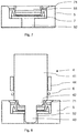
- the first set of elements comprises a transfer mandrel 2 and an insert mandrel 4
- the second set of elements comprises a flexible bearing 1 , a shifting bearing 3 and an insert bearing 5 .
- the annular flexible bearing 1 comprises four flexible arms 11 which are part of a cylindrical surface in the illustrated embodiment and are connected to each other at one end thereof.
- the number of the flexible arms 11 is not limiting and is determined particularly by the size of the spring to be transferred.
- the flexible arms 11 are on their inner side provided with protrusions 111 , which point towards the axis of the flexible bearing 1 and together with the inner side of the flexible arms 11 form a space for accommodating a circular spring 6 .
- the protrusions are part of the inner ring inside the flexible arms and form an opening whose diameter is smaller than the inner diameter of the spring 6 to be transferred.
- the outer sides of the flexible arms 11 may be provided with grooves to increase the flexibility of the flexible arms or are provided with grooves to receive auxiliary external sliding flexible elements, such as a spring or rubber O-ring.
- a cylindrically shaped lid 12 is mounted reversibly displaceably on an unillustrated pressure spring and is provided with a central protrusion 121 on its front portion, whereby when the lid 12 is pushed from the inner side towards the protrusions 111 of the flexible arms 11 , the central protrusion 121 extends above the outer side of these protrusions 111 .
- the transfer mandrel 2 comprises a cylindrical body 21 with an adjacent front portion 22 in the shape of a truncated cone.
- the body 21 and the front portion 22 of the transfer mandrel 2 are made from a single piece of material; in another embodiment, they may be removable and replaceable.
- An insert sliding sleeve 23 of annular shape is arranged reversibly displaceably in the direction of its axis around the body 21 of the transfer mandrel 2 .
- the annular insert sleeve 23 is coupled to a known unillustrated device to cause its reciprocating movement.
- the front surface of the front portion 22 of the transfer mandrel 2 has a diameter smaller than the diameter of the opening between the protrusions 111 of the flexible arms 11 .
- the shifting bearing 3 comprises a cylindrical body 31 having the same diameter as the transfer mandrel 2 .
- a recess 32 is formed whose shape is negative to the front portion 22 of the transfer mandrel 2 .
- the recess 32 is in the axis of the shifting bearing 3 provided with an opening 33 of a cylindrical shape, whose bottom constitutes a bearing surface 35 for the abutting protrusion 43 of the insert mandrel 4 , which will be described in greater detail hereinafter.
- the annular shifting sliding sleeve 34 is reversibly displaceably arranged from the outer side of the body 31 of the shifting bearing 2 in the direction of its axis, the annular shifting sliding sleeve 34 being coupled to a known unillustrated device to cause its reciprocating movement.
- the insert bearing 4 comprises a cylindrical body 41 having the same diameter as the shifting bearing 3 .
- a guide protrusion 42 of a cylindrical shape which contributes to the correct placement, i.e. centering, of the insert mandrel 4 into the workpiece 7 placed in the insert bearing 5 .
- an abutting protrusion 43 is formed which contributes to the centering of the insert mandrel 4 with respect to the shifting bearing 3 and its front surface 431 is designed to abut on the abutting bearing 35 in the shifting bearing 3 , thereby preventing undesired damage to the front surfaces of the insert mandrel 4 facing each other and surfaces of the shifting bearing 3 by the impact during the spring 6 transfer.
- the edges of the guide and abutting protrusions 42 , 43 are bevelled, which simplifies the initial centering of the insert mandrel 4 and of the shifting bearing 3 and, moreover, reduces the risk of their damage, e.g. splintering of edges, etc.
- An annular insert sliding sleeve 44 is mounted reversibly displaceably around the cylindrical body 41 of the insert mandrel 4 in the direction of its axis, the insert sliding sleeve 44 being coupled to a known unillustrated device to cause its reciprocating motion.
- the insert bearing 5 comprises a recess 51 on its front side, into which a workpiece 7 is inserted, e.g. a shaft seal.
- a workpiece 7 e.g. a shaft seal.
- an opening 52 is provided, which forms a space for the abutting protusion 43 of the insert mandrel 4 .
- the above-described device for the automatic mounting of circular springs works in such a manner that the circular spring 6 is transferred with the aid of mandrels and bearings from the flexible bearing 1 to the groove 71 of a shaft seal, which in the illustrated embodiment constitutes a workpiece 7 .
- a circular spring 6 the position of which is partially centered by the central protrusion 121 of the slidably mounted lid 12 and the inner wall of the flexible arms 11 of the flexible bearing 1 , is manually inserted by the machine operator or by a separator from a vibrating feeder.
- the transfer mandrel 2 moves along the linear track above the flexible bearing 1 with the circular spring 6 placed thereon and after that it is moved towards the flexible bearing 1 .
- the slidably mounted lid 12 is pushed into the inner part of the flexible bearing 1 and, at the same time, the free ends of the flexible arms 11 are pushed apart upon the contact of the inner protrusions 111 with the rising flat front portion 22 of the transfer mandrel.
- the spring 6 is pushed by the front side of the inner protrusions 111 along the rising surface of the front portion 22 of the transfer mandrel 2 and extends until it is moved onto the body 21 of the transfer mandrel 2 . Afterwards, the transfer mandrel 2 is pushed back to the linear track along with the spring 6 placed thereon.
- the transfer mandrel 2 moves along the linear track above the shifting bearing 3 and subsequently abuts on and simultaneously the front portion 22 of the transfer mandrel 2 is inserted into the recess 33 of the shifting bearing 3 .
- the transfer sliding sleeve 23 mounted around the body 21 of the transfer mandrel 2 moves towards the shifting bearing 3 , thereby simultaneously moving the spring 6 placed on the body of the transfer mandrel 2 onto the body of the shifting bearing 3 . Subsequently, the transfer mandrel 2 is pushed back to the linear track.
- the insert mandrel 4 moves above the shifting bearing 3 and subsequently abuts on it, whereby the abutting protrusion 43 of the insert mandrel 4 abuts on the bearing surface 35 , which constitutes the bottom of the opening 33 of the shifting bearing 3 .
- the shifting sliding sleeve 34 mounted around the body 31 of the shifting bearing 3 moves towards the insert mandrel 4 , pushing the spring 6 in front of it, thereby moving the spring 6 onto the body 41 of the insert mandrel 4 and subsequently the insert mandrel 4 moves back to the linear track.
- the insert mandrel 4 moves along the linear track above the insert bearing 5 , in whose recess 51 the workpiece 7 is placed and then the insert mandrel 4 abuts on the workpiece 7 , whereby the guide protrusion 43 is inserted into the workpiece 7 .
- the insert sliding sleeve 44 begins to move towards the insert bearing 5 , pushing the spring 6 in front of it.
- the spring engages into the groove 71 of the workpiece 7 and reduces its diameter, thereby placing the spring 6 in the desired position. Subsequently, the insert mandrel 4 is pushed back to the linear track and thereby allows the workpiece 7 to be removed.
Landscapes
- Engineering & Computer Science (AREA)
- Mechanical Engineering (AREA)
- Automatic Assembly (AREA)
Applications Claiming Priority (1)
| Application Number | Priority Date | Filing Date | Title |
|---|---|---|---|
| CZ2017-496A CZ307496B6 (cs) | 2017-08-29 | 2017-08-29 | Způsob navlékání kruhových toroidních pružinek do vnějších drážek pracovních dílů a zařízení k jeho provádění |
Publications (2)
| Publication Number | Publication Date |
|---|---|
| EP3456476A1 true EP3456476A1 (fr) | 2019-03-20 |
| EP3456476B1 EP3456476B1 (fr) | 2021-08-25 |
Family
ID=63791145
Family Applications (1)
| Application Number | Title | Priority Date | Filing Date |
|---|---|---|---|
| EP18191094.4A Active EP3456476B1 (fr) | 2017-08-29 | 2018-08-28 | Procédé de mise en place de ressorts toroïdaux circulaires dans des rainures extérieures de pièces à usiner et son dispositif de mise en oeuvre |
Country Status (2)
| Country | Link |
|---|---|
| EP (1) | EP3456476B1 (fr) |
| CZ (1) | CZ307496B6 (fr) |
Cited By (3)
| Publication number | Priority date | Publication date | Assignee | Title |
|---|---|---|---|---|
| CN112847234A (zh) * | 2020-12-22 | 2021-05-28 | 建德市三业金属制造有限公司 | 一种桶口座密封圈安装装置 |
| WO2022063631A1 (fr) * | 2020-09-28 | 2022-03-31 | Magna powertrain gmbh & co kg | Outil de montage permettant le positionnement d'une bague d'étanchéité d'arbre sur un arbre et procédé de fabrication d'un joint d'étanchéité d'arbre |
| CN117484436A (zh) * | 2023-12-17 | 2024-02-02 | 江西财经大学 | 一种纽扣式储能元件密封圈嵌套工具 |
Citations (4)
| Publication number | Priority date | Publication date | Assignee | Title |
|---|---|---|---|---|
| US20040194277A1 (en) * | 2003-03-14 | 2004-10-07 | Michael Hunter | Single stroke O-ring insertion device |
| CN203831341U (zh) * | 2014-05-21 | 2014-09-17 | 常州宝菱重工机械有限公司 | 密封圈装配导入工具 |
| US20150224613A1 (en) * | 2012-08-28 | 2015-08-13 | Nissan Motor Co., Ltd. | Device for press-fitting oil seal |
| WO2017057181A1 (fr) * | 2015-09-29 | 2017-04-06 | Kyb株式会社 | Dispositif d'extraction d'élément d'étanchéité |
Family Cites Families (6)
| Publication number | Priority date | Publication date | Assignee | Title |
|---|---|---|---|---|
| DE19815442A1 (de) * | 1998-04-07 | 1999-10-14 | Freudenberg Carl Fa | Verfahren und Vorrichtung zum Einfügen einer ringförmigen Feder in eine radial nach außen offene Nut einer ringförmigen Dichtlippe einer Wellen- oder Stangendichtung |
| CN201872136U (zh) * | 2010-11-17 | 2011-06-22 | 中冶陕压重工设备有限公司 | 活塞杆用密封圈安装工具 |
| CN202668483U (zh) * | 2012-03-02 | 2013-01-16 | 昌河飞机工业(集团)有限责任公司 | 耐磨密封圈安装器 |
| CN203401447U (zh) * | 2013-08-26 | 2014-01-22 | 上海贝洱热系统有限公司 | O形圈装配工具 |
| CN105179694B (zh) * | 2015-06-17 | 2018-08-31 | 北京精密机电控制设备研究所 | 实现组合式密封件引装或整形的装置及安装方法 |
| CN105757251A (zh) * | 2016-05-06 | 2016-07-13 | 张辉 | 一种轴密封安装工具及安装方法 |
-
2017
- 2017-08-29 CZ CZ2017-496A patent/CZ307496B6/cs unknown
-
2018
- 2018-08-28 EP EP18191094.4A patent/EP3456476B1/fr active Active
Patent Citations (4)
| Publication number | Priority date | Publication date | Assignee | Title |
|---|---|---|---|---|
| US20040194277A1 (en) * | 2003-03-14 | 2004-10-07 | Michael Hunter | Single stroke O-ring insertion device |
| US20150224613A1 (en) * | 2012-08-28 | 2015-08-13 | Nissan Motor Co., Ltd. | Device for press-fitting oil seal |
| CN203831341U (zh) * | 2014-05-21 | 2014-09-17 | 常州宝菱重工机械有限公司 | 密封圈装配导入工具 |
| WO2017057181A1 (fr) * | 2015-09-29 | 2017-04-06 | Kyb株式会社 | Dispositif d'extraction d'élément d'étanchéité |
Cited By (5)
| Publication number | Priority date | Publication date | Assignee | Title |
|---|---|---|---|---|
| WO2022063631A1 (fr) * | 2020-09-28 | 2022-03-31 | Magna powertrain gmbh & co kg | Outil de montage permettant le positionnement d'une bague d'étanchéité d'arbre sur un arbre et procédé de fabrication d'un joint d'étanchéité d'arbre |
| US12564923B2 (en) | 2020-09-28 | 2026-03-03 | Magna powertrain gmbh & co kg | Mounting tool for positioning a shaft sealing ring on a shaft and method for producing a shaft seal |
| CN112847234A (zh) * | 2020-12-22 | 2021-05-28 | 建德市三业金属制造有限公司 | 一种桶口座密封圈安装装置 |
| CN112847234B (zh) * | 2020-12-22 | 2022-08-12 | 建德市三业金属制造有限公司 | 一种桶口座密封圈安装装置 |
| CN117484436A (zh) * | 2023-12-17 | 2024-02-02 | 江西财经大学 | 一种纽扣式储能元件密封圈嵌套工具 |
Also Published As
| Publication number | Publication date |
|---|---|
| CZ2017496A3 (cs) | 2018-10-17 |
| CZ307496B6 (cs) | 2018-10-17 |
| EP3456476B1 (fr) | 2021-08-25 |
Similar Documents
| Publication | Publication Date | Title |
|---|---|---|
| EP3456476B1 (fr) | Procédé de mise en place de ressorts toroïdaux circulaires dans des rainures extérieures de pièces à usiner et son dispositif de mise en oeuvre | |
| US3605239A (en) | Apparatus for external installation of resilient seals | |
| KR102865944B1 (ko) | 이동 부품 분류 유닛 | |
| KR100978319B1 (ko) | 선반용 자동배출식 척 | |
| CN104874988B (zh) | O型环安装装置及方法、o型环安装治具、及多关节型机器人 | |
| US7047618B2 (en) | Single stroke O-ring insertion device | |
| US10486310B2 (en) | Robot tool for setting sealing plugs | |
| EP3202530A1 (fr) | Dispositif et procédé de montage de joint torique | |
| RU2017135398A (ru) | Устройство и способ вставки вкладыша в вертлужную чашку | |
| EP4253021A1 (fr) | Dispositif d'insertion forcée d'objets en général à insérer dans un siège pré-difin | |
| CN108778614B (zh) | 用于将圆形坯料环插入到圆形坯料的外环中的方法和插入装置 | |
| JP2023001578A (ja) | Oリング組付け機構及びoリング組付け方法 | |
| CN104227403B (zh) | 压装装置 | |
| KR101462702B1 (ko) | 금속 용기를 그리핑하고 핸들링하기 위한 장치 | |
| EP1652622A1 (fr) | Dispositif pour l'insertion d'une bague élastique | |
| EP3834971A4 (fr) | Procédé de confirmation de précision de serrage de mandrin, procédé de remplacement de griffe de mandrin et dispositif de confirmation de précision de serrage de mandrin | |
| KR100731499B1 (ko) | 인풋샤프트의 오링 조립장치 및 방법 | |
| JP2004209621A (ja) | スナップリング組付装置 | |
| CN108406910B (zh) | 成型设备及取放治具 | |
| KR100881464B1 (ko) | 플레이트 고정용 척 | |
| US5718032A (en) | Method of jointing a flexible tubular component to the end of a main component, and device for carrying out the method | |
| JP2006255886A (ja) | 弾性リング装着治具および弾性リング装着方法 | |
| GB1559211A (en) | Method of assembling an 'o' ring on a cylindrical component and apparatus therefor | |
| US10213781B2 (en) | Method and device for orienting individual elements, in particular filter elements, during the transfer thereof further processing | |
| KR100812125B1 (ko) | 공작기계용 선반척의 원통형 탄성변형 흡수장치 |
Legal Events
| Date | Code | Title | Description |
|---|---|---|---|
| PUAI | Public reference made under article 153(3) epc to a published international application that has entered the european phase |
Free format text: ORIGINAL CODE: 0009012 |
|
| STAA | Information on the status of an ep patent application or granted ep patent |
Free format text: STATUS: THE APPLICATION HAS BEEN PUBLISHED |
|
| AK | Designated contracting states |
Kind code of ref document: A1 Designated state(s): AL AT BE BG CH CY CZ DE DK EE ES FI FR GB GR HR HU IE IS IT LI LT LU LV MC MK MT NL NO PL PT RO RS SE SI SK SM TR |
|
| AX | Request for extension of the european patent |
Extension state: BA ME |
|
| STAA | Information on the status of an ep patent application or granted ep patent |
Free format text: STATUS: REQUEST FOR EXAMINATION WAS MADE |
|
| 17P | Request for examination filed |
Effective date: 20190718 |
|
| RBV | Designated contracting states (corrected) |
Designated state(s): AL AT BE BG CH CY CZ DE DK EE ES FI FR GB GR HR HU IE IS IT LI LT LU LV MC MK MT NL NO PL PT RO RS SE SI SK SM TR |
|
| RIC1 | Information provided on ipc code assigned before grant |
Ipc: B25B 27/00 20060101AFI20191105BHEP Ipc: F16J 15/3268 20160101ALI20191105BHEP Ipc: B23P 19/08 20060101ALI20191105BHEP |
|
| STAA | Information on the status of an ep patent application or granted ep patent |
Free format text: STATUS: EXAMINATION IS IN PROGRESS |
|
| 17Q | First examination report despatched |
Effective date: 20200706 |
|
| GRAP | Despatch of communication of intention to grant a patent |
Free format text: ORIGINAL CODE: EPIDOSNIGR1 |
|
| STAA | Information on the status of an ep patent application or granted ep patent |
Free format text: STATUS: GRANT OF PATENT IS INTENDED |
|
| INTG | Intention to grant announced |
Effective date: 20210312 |
|
| GRAS | Grant fee paid |
Free format text: ORIGINAL CODE: EPIDOSNIGR3 |
|
| GRAA | (expected) grant |
Free format text: ORIGINAL CODE: 0009210 |
|
| STAA | Information on the status of an ep patent application or granted ep patent |
Free format text: STATUS: THE PATENT HAS BEEN GRANTED |
|
| AK | Designated contracting states |
Kind code of ref document: B1 Designated state(s): AL AT BE BG CH CY CZ DE DK EE ES FI FR GB GR HR HU IE IS IT LI LT LU LV MC MK MT NL NO PL PT RO RS SE SI SK SM TR |
|
| REG | Reference to a national code |
Ref country code: CH Ref legal event code: EP |
|
| REG | Reference to a national code |
Ref country code: IE Ref legal event code: FG4D Ref country code: AT Ref legal event code: REF Ref document number: 1423305 Country of ref document: AT Kind code of ref document: T Effective date: 20210915 |
|
| REG | Reference to a national code |
Ref country code: DE Ref legal event code: R096 Ref document number: 602018022290 Country of ref document: DE |
|
| PGFP | Annual fee paid to national office [announced via postgrant information from national office to epo] |
Ref country code: DE Payment date: 20210907 Year of fee payment: 4 |
|
| REG | Reference to a national code |
Ref country code: LT Ref legal event code: MG9D |
|
| REG | Reference to a national code |
Ref country code: NL Ref legal event code: MP Effective date: 20210825 |
|
| REG | Reference to a national code |
Ref country code: AT Ref legal event code: MK05 Ref document number: 1423305 Country of ref document: AT Kind code of ref document: T Effective date: 20210825 |
|
| PG25 | Lapsed in a contracting state [announced via postgrant information from national office to epo] |
Ref country code: RS Free format text: LAPSE BECAUSE OF FAILURE TO SUBMIT A TRANSLATION OF THE DESCRIPTION OR TO PAY THE FEE WITHIN THE PRESCRIBED TIME-LIMIT Effective date: 20210825 Ref country code: SE Free format text: LAPSE BECAUSE OF FAILURE TO SUBMIT A TRANSLATION OF THE DESCRIPTION OR TO PAY THE FEE WITHIN THE PRESCRIBED TIME-LIMIT Effective date: 20210825 Ref country code: FI Free format text: LAPSE BECAUSE OF FAILURE TO SUBMIT A TRANSLATION OF THE DESCRIPTION OR TO PAY THE FEE WITHIN THE PRESCRIBED TIME-LIMIT Effective date: 20210825 Ref country code: ES Free format text: LAPSE BECAUSE OF FAILURE TO SUBMIT A TRANSLATION OF THE DESCRIPTION OR TO PAY THE FEE WITHIN THE PRESCRIBED TIME-LIMIT Effective date: 20210825 Ref country code: HR Free format text: LAPSE BECAUSE OF FAILURE TO SUBMIT A TRANSLATION OF THE DESCRIPTION OR TO PAY THE FEE WITHIN THE PRESCRIBED TIME-LIMIT Effective date: 20210825 Ref country code: BG Free format text: LAPSE BECAUSE OF FAILURE TO SUBMIT A TRANSLATION OF THE DESCRIPTION OR TO PAY THE FEE WITHIN THE PRESCRIBED TIME-LIMIT Effective date: 20211125 Ref country code: AT Free format text: LAPSE BECAUSE OF FAILURE TO SUBMIT A TRANSLATION OF THE DESCRIPTION OR TO PAY THE FEE WITHIN THE PRESCRIBED TIME-LIMIT Effective date: 20210825 Ref country code: LT Free format text: LAPSE BECAUSE OF FAILURE TO SUBMIT A TRANSLATION OF THE DESCRIPTION OR TO PAY THE FEE WITHIN THE PRESCRIBED TIME-LIMIT Effective date: 20210825 Ref country code: PT Free format text: LAPSE BECAUSE OF FAILURE TO SUBMIT A TRANSLATION OF THE DESCRIPTION OR TO PAY THE FEE WITHIN THE PRESCRIBED TIME-LIMIT Effective date: 20211227 Ref country code: NO Free format text: LAPSE BECAUSE OF FAILURE TO SUBMIT A TRANSLATION OF THE DESCRIPTION OR TO PAY THE FEE WITHIN THE PRESCRIBED TIME-LIMIT Effective date: 20211125 |
|
| PG25 | Lapsed in a contracting state [announced via postgrant information from national office to epo] |
Ref country code: PL Free format text: LAPSE BECAUSE OF FAILURE TO SUBMIT A TRANSLATION OF THE DESCRIPTION OR TO PAY THE FEE WITHIN THE PRESCRIBED TIME-LIMIT Effective date: 20210825 Ref country code: LV Free format text: LAPSE BECAUSE OF FAILURE TO SUBMIT A TRANSLATION OF THE DESCRIPTION OR TO PAY THE FEE WITHIN THE PRESCRIBED TIME-LIMIT Effective date: 20210825 Ref country code: GR Free format text: LAPSE BECAUSE OF FAILURE TO SUBMIT A TRANSLATION OF THE DESCRIPTION OR TO PAY THE FEE WITHIN THE PRESCRIBED TIME-LIMIT Effective date: 20211126 |
|
| REG | Reference to a national code |
Ref country code: CH Ref legal event code: PL |
|
| PG25 | Lapsed in a contracting state [announced via postgrant information from national office to epo] |
Ref country code: NL Free format text: LAPSE BECAUSE OF FAILURE TO SUBMIT A TRANSLATION OF THE DESCRIPTION OR TO PAY THE FEE WITHIN THE PRESCRIBED TIME-LIMIT Effective date: 20210825 |
|
| REG | Reference to a national code |
Ref country code: BE Ref legal event code: MM Effective date: 20210831 |
|
| PG25 | Lapsed in a contracting state [announced via postgrant information from national office to epo] |
Ref country code: LI Free format text: LAPSE BECAUSE OF NON-PAYMENT OF DUE FEES Effective date: 20210831 Ref country code: DK Free format text: LAPSE BECAUSE OF FAILURE TO SUBMIT A TRANSLATION OF THE DESCRIPTION OR TO PAY THE FEE WITHIN THE PRESCRIBED TIME-LIMIT Effective date: 20210825 Ref country code: CH Free format text: LAPSE BECAUSE OF NON-PAYMENT OF DUE FEES Effective date: 20210831 |
|
| REG | Reference to a national code |
Ref country code: DE Ref legal event code: R097 Ref document number: 602018022290 Country of ref document: DE |
|
| PG25 | Lapsed in a contracting state [announced via postgrant information from national office to epo] |
Ref country code: SM Free format text: LAPSE BECAUSE OF FAILURE TO SUBMIT A TRANSLATION OF THE DESCRIPTION OR TO PAY THE FEE WITHIN THE PRESCRIBED TIME-LIMIT Effective date: 20210825 Ref country code: SK Free format text: LAPSE BECAUSE OF FAILURE TO SUBMIT A TRANSLATION OF THE DESCRIPTION OR TO PAY THE FEE WITHIN THE PRESCRIBED TIME-LIMIT Effective date: 20210825 Ref country code: RO Free format text: LAPSE BECAUSE OF FAILURE TO SUBMIT A TRANSLATION OF THE DESCRIPTION OR TO PAY THE FEE WITHIN THE PRESCRIBED TIME-LIMIT Effective date: 20210825 Ref country code: MC Free format text: LAPSE BECAUSE OF FAILURE TO SUBMIT A TRANSLATION OF THE DESCRIPTION OR TO PAY THE FEE WITHIN THE PRESCRIBED TIME-LIMIT Effective date: 20210825 Ref country code: LU Free format text: LAPSE BECAUSE OF NON-PAYMENT OF DUE FEES Effective date: 20210828 Ref country code: EE Free format text: LAPSE BECAUSE OF FAILURE TO SUBMIT A TRANSLATION OF THE DESCRIPTION OR TO PAY THE FEE WITHIN THE PRESCRIBED TIME-LIMIT Effective date: 20210825 Ref country code: CZ Free format text: LAPSE BECAUSE OF FAILURE TO SUBMIT A TRANSLATION OF THE DESCRIPTION OR TO PAY THE FEE WITHIN THE PRESCRIBED TIME-LIMIT Effective date: 20210825 Ref country code: AL Free format text: LAPSE BECAUSE OF FAILURE TO SUBMIT A TRANSLATION OF THE DESCRIPTION OR TO PAY THE FEE WITHIN THE PRESCRIBED TIME-LIMIT Effective date: 20210825 |
|
| PLBE | No opposition filed within time limit |
Free format text: ORIGINAL CODE: 0009261 |
|
| STAA | Information on the status of an ep patent application or granted ep patent |
Free format text: STATUS: NO OPPOSITION FILED WITHIN TIME LIMIT |
|
| PG25 | Lapsed in a contracting state [announced via postgrant information from national office to epo] |
Ref country code: IT Free format text: LAPSE BECAUSE OF FAILURE TO SUBMIT A TRANSLATION OF THE DESCRIPTION OR TO PAY THE FEE WITHIN THE PRESCRIBED TIME-LIMIT Effective date: 20210825 Ref country code: IE Free format text: LAPSE BECAUSE OF NON-PAYMENT OF DUE FEES Effective date: 20210828 Ref country code: BE Free format text: LAPSE BECAUSE OF NON-PAYMENT OF DUE FEES Effective date: 20210831 |
|
| 26N | No opposition filed |
Effective date: 20220527 |
|
| PG25 | Lapsed in a contracting state [announced via postgrant information from national office to epo] |
Ref country code: SI Free format text: LAPSE BECAUSE OF FAILURE TO SUBMIT A TRANSLATION OF THE DESCRIPTION OR TO PAY THE FEE WITHIN THE PRESCRIBED TIME-LIMIT Effective date: 20210825 |
|
| PG25 | Lapsed in a contracting state [announced via postgrant information from national office to epo] |
Ref country code: FR Free format text: LAPSE BECAUSE OF NON-PAYMENT OF DUE FEES Effective date: 20211025 |
|
| REG | Reference to a national code |
Ref country code: DE Ref legal event code: R119 Ref document number: 602018022290 Country of ref document: DE |
|
| GBPC | Gb: european patent ceased through non-payment of renewal fee |
Effective date: 20220828 |
|
| PG25 | Lapsed in a contracting state [announced via postgrant information from national office to epo] |
Ref country code: CY Free format text: LAPSE BECAUSE OF FAILURE TO SUBMIT A TRANSLATION OF THE DESCRIPTION OR TO PAY THE FEE WITHIN THE PRESCRIBED TIME-LIMIT Effective date: 20210825 |
|
| PG25 | Lapsed in a contracting state [announced via postgrant information from national office to epo] |
Ref country code: HU Free format text: LAPSE BECAUSE OF FAILURE TO SUBMIT A TRANSLATION OF THE DESCRIPTION OR TO PAY THE FEE WITHIN THE PRESCRIBED TIME-LIMIT; INVALID AB INITIO Effective date: 20180828 Ref country code: DE Free format text: LAPSE BECAUSE OF NON-PAYMENT OF DUE FEES Effective date: 20230301 |
|
| PG25 | Lapsed in a contracting state [announced via postgrant information from national office to epo] |
Ref country code: GB Free format text: LAPSE BECAUSE OF NON-PAYMENT OF DUE FEES Effective date: 20220828 |
|
| PG25 | Lapsed in a contracting state [announced via postgrant information from national office to epo] |
Ref country code: MK Free format text: LAPSE BECAUSE OF FAILURE TO SUBMIT A TRANSLATION OF THE DESCRIPTION OR TO PAY THE FEE WITHIN THE PRESCRIBED TIME-LIMIT Effective date: 20210825 |
|
| PG25 | Lapsed in a contracting state [announced via postgrant information from national office to epo] |
Ref country code: TR Free format text: LAPSE BECAUSE OF FAILURE TO SUBMIT A TRANSLATION OF THE DESCRIPTION OR TO PAY THE FEE WITHIN THE PRESCRIBED TIME-LIMIT Effective date: 20210825 |
|
| PG25 | Lapsed in a contracting state [announced via postgrant information from national office to epo] |
Ref country code: MT Free format text: LAPSE BECAUSE OF FAILURE TO SUBMIT A TRANSLATION OF THE DESCRIPTION OR TO PAY THE FEE WITHIN THE PRESCRIBED TIME-LIMIT Effective date: 20210825 |