EP3456596A1 - Verfahren und vorrichtung zur vorhersage einer möglichen kollision - Google Patents
Verfahren und vorrichtung zur vorhersage einer möglichen kollision Download PDFInfo
- Publication number
- EP3456596A1 EP3456596A1 EP17465548.0A EP17465548A EP3456596A1 EP 3456596 A1 EP3456596 A1 EP 3456596A1 EP 17465548 A EP17465548 A EP 17465548A EP 3456596 A1 EP3456596 A1 EP 3456596A1
- Authority
- EP
- European Patent Office
- Prior art keywords
- ego vehicle
- target
- path
- computed
- core path
- Prior art date
- Legal status (The legal status is an assumption and is not a legal conclusion. Google has not performed a legal analysis and makes no representation as to the accuracy of the status listed.)
- Withdrawn
Links
Images



Classifications
-
- B—PERFORMING OPERATIONS; TRANSPORTING
- B60—VEHICLES IN GENERAL
- B60W—CONJOINT CONTROL OF VEHICLE SUB-UNITS OF DIFFERENT TYPE OR DIFFERENT FUNCTION; CONTROL SYSTEMS SPECIALLY ADAPTED FOR HYBRID VEHICLES; ROAD VEHICLE DRIVE CONTROL SYSTEMS FOR PURPOSES NOT RELATED TO THE CONTROL OF A PARTICULAR SUB-UNIT
- B60W30/00—Purposes of road vehicle drive control systems not related to the control of a particular sub-unit, e.g. of systems using conjoint control of vehicle sub-units
- B60W30/08—Active safety systems predicting or avoiding probable or impending collision or attempting to minimise its consequences
- B60W30/095—Predicting travel path or likelihood of collision
-
- B—PERFORMING OPERATIONS; TRANSPORTING
- B60—VEHICLES IN GENERAL
- B60W—CONJOINT CONTROL OF VEHICLE SUB-UNITS OF DIFFERENT TYPE OR DIFFERENT FUNCTION; CONTROL SYSTEMS SPECIALLY ADAPTED FOR HYBRID VEHICLES; ROAD VEHICLE DRIVE CONTROL SYSTEMS FOR PURPOSES NOT RELATED TO THE CONTROL OF A PARTICULAR SUB-UNIT
- B60W2540/00—Input parameters relating to occupants
- B60W2540/18—Steering angle
-
- B—PERFORMING OPERATIONS; TRANSPORTING
- B60—VEHICLES IN GENERAL
- B60W—CONJOINT CONTROL OF VEHICLE SUB-UNITS OF DIFFERENT TYPE OR DIFFERENT FUNCTION; CONTROL SYSTEMS SPECIALLY ADAPTED FOR HYBRID VEHICLES; ROAD VEHICLE DRIVE CONTROL SYSTEMS FOR PURPOSES NOT RELATED TO THE CONTROL OF A PARTICULAR SUB-UNIT
- B60W2554/00—Input parameters relating to objects
-
- B—PERFORMING OPERATIONS; TRANSPORTING
- B60—VEHICLES IN GENERAL
- B60W—CONJOINT CONTROL OF VEHICLE SUB-UNITS OF DIFFERENT TYPE OR DIFFERENT FUNCTION; CONTROL SYSTEMS SPECIALLY ADAPTED FOR HYBRID VEHICLES; ROAD VEHICLE DRIVE CONTROL SYSTEMS FOR PURPOSES NOT RELATED TO THE CONTROL OF A PARTICULAR SUB-UNIT
- B60W2554/00—Input parameters relating to objects
- B60W2554/40—Dynamic objects, e.g. animals, windblown objects
- B60W2554/404—Characteristics
- B60W2554/4044—Direction of movement, e.g. backwards
-
- B—PERFORMING OPERATIONS; TRANSPORTING
- B60—VEHICLES IN GENERAL
- B60W—CONJOINT CONTROL OF VEHICLE SUB-UNITS OF DIFFERENT TYPE OR DIFFERENT FUNCTION; CONTROL SYSTEMS SPECIALLY ADAPTED FOR HYBRID VEHICLES; ROAD VEHICLE DRIVE CONTROL SYSTEMS FOR PURPOSES NOT RELATED TO THE CONTROL OF A PARTICULAR SUB-UNIT
- B60W2554/00—Input parameters relating to objects
- B60W2554/80—Spatial relation or speed relative to objects
Definitions
- the invention refers to a method and device of predicting a possible collision of a vehicle with an oncoming moving object, intended mainly for mitigate lateral collision.
- radar sensors are used in order to increase the safety of the cars, either by alerting the driver of an important danger or by triggering autonomous reactions, which can involve braking or steering the car, in case of imminent collisions.
- Short-range radars endowed with large field of views, are mounted on a car's corners monitor large areas around the car and can be used in order to predict probable lateral collisions with other cars.
- Functions that alert the user about such probable collisions are already in use in passenger cars, but often they consider straight, linear trajectories to predict an intersection point, which may be sufficient for driver alert functions, for low driving speeds, or when the host vehicle is standing, but which can cause issues for more important decisions, like having to automatically brake or to steer the car in order to increase the safety of passengers.
- Patent US8060306B2 discloses a method and system for avoiding an obstacle.
- the system comprises a mapping module or path filtering module which is arranged to identify admissible curved paths for which the vehicle is able to stop prior to reaching a detected obstacle in accordance with an observed translational velocity and an observed rotational velocity.
- a data processor determines a respective objective function for the candidate translational velocities and candidate rotational velocities associated with the admissible curved paths, where the objective function includes a curvature comparison term associated with the last curved path of the vehicle.
- a search engine or data processor selects preferential velocities, among the candidate translational velocities and candidate rotational velocities, with a superior value for its corresponding objective function, and the path planning module or data processor determines the vehicular speed and trajectory for a path plan that avoids the obstacle consistent with the selected preferential velocities.
- the invention takes into consideration the subject vehicle's path as a series of admissible curved paths, but it concerns only the case of a possible collision with a static obstacle, not a moving one.
- Another patent document, US 5841366 discloses a traveling-path deduction apparatus and method.
- the said method is able to detect objects existing ahead of the vehicle and to deduce a temporary traveling path of the vehicle and to set the traveling path having the minimum time change amount in the distances. It is said that in case of a properly-set temporary traveling path, the path and running loci of the preceding vehicles are on a concentric circle.
- having to compute a plurality of temporary traveling paths with different curvatures requires a lot of computing resources, when the preceding vehicle (or the vehicle ahead) does not follow a straight trajectory.
- the object of the invention is to indicate means for accurately avoiding collision between an ego vehicle and a target vehicle, when at least one of them follows a curved path.
- the invention provides a method of predicting a possible collision of an ego vehicle with a target vehicle, at least one of them following a curve path.
- a traffic participant entering in a predetermined scanning area is selected and traced as a target. Its approximated current core path is constructed, and a core path of the ego vehicle is computed as well.
- the ego vehicle core path is predicted by extrapolation up to a maximum admissible value, and the intersecting points of the respective core paths are computed.
- a possible collision of the ego vehicle with the target is predicted based on the probability for the ego vehicle to reach the most critical intersection points within a predefined time interval.
- the invention provides a device of predicting a possible collision, which comprises an interface and an evaluation unit.
- the interface is adapted to receive sensor data related to the target, as well as ego vehicle data such as length, width, position of the rear axle and steering angle.
- the evaluation unit is adapted to construct the approximated core path of the target based on the received sensor data, then to compute the core path of the ego vehicle, to predict the ego vehicle core path up to a maximum admissible value and to compute the intersection points of respective core paths.
- the evaluation unit also is adapted to compute the probability for the ego vehicle to reach those points under a predefined time interval.
- the invention provides a vehicle equipped with a sensor system adapted to provide sensor data of a surrounding of the ego vehicle, and steering and/or braking systems able to receive signals from a device for predicting a possible collision.
- the most critical distance to the intersection between a steering ego vehicle and a target vehicle having crossing paths is accurately computed. Having this distance computed, a more precise time to crossing is computed for each of the two implied vehicles, and further on it is possible to autonomously take a better decision, for example when to automatically apply a brake.
- the method also enriches the set of possible scenarios of avoidance of lateral collisions and it increases as well the false positive performance. Also, the considered function can be executed, this way, in other situations as well, like the case when target vehicle is steering.
- the critical distance required to be travelled by the ego vehicle to intersect the target is computed.
- it is computed the time to crossing the computed critical distance by the ego vehicle.
- it is defined a threshold that identify a time to collision with the target by the ego vehicle, and providing signals to the ego vehicle to effect the ego vehicle steering or braking systems, when the computed time to crossing exceeds the defined time to collision.
- the curvilinear core path is delimited by the curves given by the radiuses of the circles described by all four corners of the ego vehicle.
- the maximum length of the core path for the ego vehicle corresponds to a steer angle of 180°.
- the current approximated core path of the target is constructed using regression.
- the curvilinear path of the ego vehicle is computed as a circular path when the steering angle of the ego vehicle is constant.
- the curvilinear path of the ego vehicle is computed as a combination of curvilinear and rectilinear parts.
- the curvilinear path is computed as a part of complex curve, like parabola, clothoid, or the like, when the steering angle of the ego vehicle is not constant.
- the evaluation unit is adapted to construct the current approximated core path of the target using regression.
- the evaluation unit is adapted to compute the critical distance required to be travelled by the ego vehicle to intersect the target.
- the evaluation unit is adapted to compute the critical distance required to be travelled by the ego vehicle to intersect the target.
- the evaluation unit is adapted to compute a time to crossing the computed critical distance for ego vehicle.
- the evaluation unit is further adapted to define a threshold that identify a time to collision with the target by the ego vehicle, and providing signals to the ego vehicle to effect the ego vehicle steering or braking systems, when the computed time to crossing exceeds the defined time to collision.
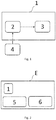
- Fig. 1 shows a schematic block diagram of a device 1 for predicting a possible collision of an ego vehicle E with another traffic participant, designated as target T.
- the traffic participant can be, in the context of the invention, a moving object (described as a rectangle), such as a motor vehicle, a motorcycle/bicycle or alike.
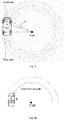
- FIG. 2 A schematic view of an ego vehicle E equipped with such a device 1 and with systems of sensing 4, steering 5 and braking 6 is illustrated in Fig. 2 .
- the device 1 comprises an interface 2 which is adapted to receive input data from any active form of remote sensing, such as radar, lidar, optic or infrared sensors, for example.
- the received input data are related to a target external to said ego vehicle E, said target T being present in a predetermined scanning zone of the sensing system 4.
- the traffic participant designated as target T in this description is an oncoming vehicle, whose direction (angle) of movement over ground has been detected and history of measurement positions has been generated as a trace.
- the device 1 comprises an evaluation unit 3 adapted to construct an approximated path (trajectory) of target T based on the measured trace, for example, using regression.
- the core can be considered the curve parallel to the computed trajectory that contains the intersection of the diagonals (for rectangle objects, as in the illustrated case), and the edges of the path are the parallels that contain the corners considered in the direction of movement of target T.
- the evaluation unit 3 is further adapted to compute the probability for the ego vehicle E to reach the most critical intersection points within a predefined time interval, according to the method which is described in detail in the following section.
- ego vehicle E follows a circular path, i.e. having a constant curve, with a constant speed.
- the curve driven by a modern car can be obtained via the vehicle's CAN. It is computed based on information obtained from steering angle sensors. For the position of the steering wheel considered, the car is supposed to drive on a circle. That's why the curve information is computed as 1/R, where R is the radius of the circle on which the center of gravity CoG of the car is considered to run in that specific moment. Every other point of the car will describe a circle that is concentric with this one and so are the wheels of the car, which are tangent, in their middle, to such circles. The center of these circles, called the center of rotation CoR of the vehicle, is on the line that contains the rear axle of the car, as shown in Fig. 3 .
- the value of the radical alone is the radius of the circle that contains the center of the rear axle, R Ra .
- the CoG circle is what is called the core of the path (there are given later more details about it), on which the distance to be run by the vehicle can be computed, and on which the overall speed is also computed. It is considered to be an appropriate choice, because of the fact that it has the radius close to the average of the radiuses of the circles described by all the four wheels, as it is approximately in the middle of the car.
- the path prediction for an at most 180 degrees turn of the car is taken into consideration, as shown in Fig. 4a or 4b , as turns of a greater angle are not plausible in practice. For high curve values this is the path to consider, while for lower curves the path will be limited to a certain maximum length.
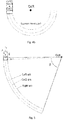
- the maximum length, L max is chosen based on important properties of the function, as the maximum speed limit and the considered time to crossing values, and it is considered as length of the CoG arc of circle, starting from the ego vehicle side (i.e. front or rear).
- the other arcs are limited to the intersection with the line containing the CoR and the end of the CoG arc, as seen in Fig. 5 .
- L ⁇ ⁇ ⁇ ⁇ R CoG
- ⁇ arcsin d Ra R CoG
- d Ra is the distance between the rear axle and the considered side, which distance can be easily determined from car's length and the position of the rear axle.
- the next step it is to find out the interval in which the Y coordinates of the points from the three circles are included.
- y end_left and y end_right are computed similarly.
- the next step, which computes the distance to crossing, is dependent on these intervals, as well as on the previously computed center of rotation and corresponding radiuses.
- the device 3 is afterwards able to compute the intersection points between all the path edges by equalizing the equations. This can be generalized for any possible curve type.
- x ⁇ R 2 ⁇ y ⁇ y CoR 2 ⁇ x CoR ) the minus sign being associated with driving backwards, where R is the radius of the corresponding circle and y ⁇ I y,x , where I y,x is the corresponding previously computed interval delimiting the arc.
- intersection points From here at most eight intersection points are obtained. In Fig. 6 , for example, six such intersection points can be found.
- the device 3 is able to compute the critical distance to crossing, which is the distance that the ego vehicle E has to run in order to reach the most critical intersection point. Doing this, the intersection points are predicted on the core path, as in Fig. 7 .
- the evaluation unit 3 chooses the smallest one, which is the distance D of concern, until the intersection with target T following the given curved ego's E path.
- the distance will be the length of the arc from the back of ego E to the point A'.
- the computed distance can be used to find the time to crossing (or TTC) for each of the two implied vehicles, and, based on them, it is possible to autonomously take a better decision.
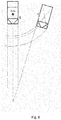
- Fig. 8 when ego vehicle has a straight path and target is predicted to have a curvilinear path bent towards ego vehicle E, the time to crossing TTC is computed more accurately. It is easy to observe, in Fig. 8 , how having computed a curved target path reduces significantly the distance to crossing for both ego E and target T, than in the case when both would have followed a straight path, situation illustrated by dashed lines. This reduces both ego's and target's time to collision (computed as distance/speed), as the speed remains the same. As TTC is one of important factors to be considered in order to take a decision, this leads to an important brake request that otherwise would have been omitted or delayed.
- FIG. 9 Another exemplary embodiment is found in Fig. 9 , where, as it can be seen, cars whose directions of movement at a certain point could be considered as intersecting for straight paths, illustrated as dashed lines, are predicted actually not to have intersecting paths. As a consequence, a false action is prevented.
- FIG. 10 another exemplary embodiment can be seen, illustrating another advantage given by this invention.
- a situation which without curved path intersections wouldn't have been a lateral collision avoidance scenario can easily be detected as such or it can, at least, be detected earlier.
- one method to detect lateral collision situations is to do an approaching angle check.
- target T might have not been detected as a critical object to take an action for, since by considering their straight paths, illustrated by interrupted lines, do not cross.
- the path intersection makes it useless to use such an approach like the one of verifying an approaching angle, because it is enough to compute the intersection of paths and to see if there's a risk of collision.
Landscapes
- Engineering & Computer Science (AREA)
- Automation & Control Theory (AREA)
- Transportation (AREA)
- Mechanical Engineering (AREA)
- Traffic Control Systems (AREA)
Priority Applications (1)
| Application Number | Priority Date | Filing Date | Title |
|---|---|---|---|
| EP17465548.0A EP3456596A1 (de) | 2017-09-14 | 2017-09-14 | Verfahren und vorrichtung zur vorhersage einer möglichen kollision |
Applications Claiming Priority (1)
| Application Number | Priority Date | Filing Date | Title |
|---|---|---|---|
| EP17465548.0A EP3456596A1 (de) | 2017-09-14 | 2017-09-14 | Verfahren und vorrichtung zur vorhersage einer möglichen kollision |
Publications (1)
| Publication Number | Publication Date |
|---|---|
| EP3456596A1 true EP3456596A1 (de) | 2019-03-20 |
Family
ID=60001846
Family Applications (1)
| Application Number | Title | Priority Date | Filing Date |
|---|---|---|---|
| EP17465548.0A Withdrawn EP3456596A1 (de) | 2017-09-14 | 2017-09-14 | Verfahren und vorrichtung zur vorhersage einer möglichen kollision |
Country Status (1)
| Country | Link |
|---|---|
| EP (1) | EP3456596A1 (de) |
Cited By (12)
| Publication number | Priority date | Publication date | Assignee | Title |
|---|---|---|---|---|
| CN110562222A (zh) * | 2019-08-30 | 2019-12-13 | 驭势(上海)汽车科技有限公司 | 用于弯道场景的紧急制动控制方法、车载设备和存储介质 |
| CN111309013A (zh) * | 2020-02-24 | 2020-06-19 | 广州小鹏汽车科技有限公司 | 一种碰撞距离确定方法及系统、车辆、存储介质 |
| CN112026762A (zh) * | 2020-09-15 | 2020-12-04 | 北京经纬恒润科技有限公司 | 一种车辆碰撞分析方法及装置 |
| CN113071482A (zh) * | 2021-04-28 | 2021-07-06 | 江苏大学 | 一种基于通行时间区间的智能车辆防碰撞方法 |
| CN113705636A (zh) * | 2021-08-12 | 2021-11-26 | 重庆邮电大学 | 一种自动驾驶车辆轨迹预测方法、装置及电子设备 |
| CN111409631B (zh) * | 2020-04-10 | 2022-01-11 | 新石器慧通(北京)科技有限公司 | 一种车辆行驶的控制方法、装置、车辆及存储介质 |
| CN114882706A (zh) * | 2022-05-31 | 2022-08-09 | 华中科技大学 | 一种基于非结构性路面的周向防碰撞预警方法及系统 |
| FR3121255A1 (fr) * | 2021-03-26 | 2022-09-30 | Psa Automobiles Sa | Procédé et dispositif de signalement d’une manœuvre de marche arrière d’un véhicule autonome. |
| EP4223604A1 (de) * | 2022-02-04 | 2023-08-09 | Renault s.a.s | Verfahren zur gefahrenerkennung in der umgebung eines kraftfahrzeugs |
| DE102022123474A1 (de) * | 2022-09-14 | 2024-03-14 | Valeo Schalter Und Sensoren Gmbh | Verfahren zum Berechnen einer prognostizierten Zeit bis zu einer möglichen Kollision zweier Kraftfahrzeuge, Computerprogramm und Fahrerassistenzsystem |
| WO2025152862A1 (zh) * | 2024-01-19 | 2025-07-24 | 北京京东远升科技有限公司 | 自动驾驶车辆行驶速度的控制方法和装置 |
| EP4603352A3 (de) * | 2024-06-28 | 2025-12-24 | Shanghai Horizon Intelligent Automotive Technology Co., Ltd. | Verfahren und vorrichtung zur bestimmung der zeit bis zur kollision, vorrichtung und speichermedium |
Citations (7)
| Publication number | Priority date | Publication date | Assignee | Title |
|---|---|---|---|---|
| US5841366A (en) | 1995-07-20 | 1998-11-24 | Mazda Motor Coporaton | Traveling-path deduction apparatus and method for vehicles |
| JP2007164339A (ja) * | 2005-12-12 | 2007-06-28 | Toyota Central Res & Dev Lab Inc | 計算処理プログラム、計算処理装置、及び計算処理方法 |
| EP2208654A1 (de) * | 2009-01-15 | 2010-07-21 | Ford Global Technologies, LLC | Verfahren und System zur Vermeidung der Kollision eines Fahrzeugs mit einem Ziel |
| US8060306B2 (en) | 2007-10-04 | 2011-11-15 | Deere & Company | Method and system for obstacle avoidance for a vehicle |
| EP2495713A1 (de) * | 2009-10-30 | 2012-09-05 | Toyota Jidosha Kabushiki Kaisha | Fahrhilfevorrichtung |
| US20140303882A1 (en) * | 2013-04-05 | 2014-10-09 | Electronics And Telecommunications Research Institute | Apparatus and method for providing intersection collision-related information |
| EP3006294A1 (de) * | 2013-05-31 | 2016-04-13 | Hitachi Automotive Systems, Ltd. | Fahrzeugsteuerungsvorrichtung |
-
2017
- 2017-09-14 EP EP17465548.0A patent/EP3456596A1/de not_active Withdrawn
Patent Citations (7)
| Publication number | Priority date | Publication date | Assignee | Title |
|---|---|---|---|---|
| US5841366A (en) | 1995-07-20 | 1998-11-24 | Mazda Motor Coporaton | Traveling-path deduction apparatus and method for vehicles |
| JP2007164339A (ja) * | 2005-12-12 | 2007-06-28 | Toyota Central Res & Dev Lab Inc | 計算処理プログラム、計算処理装置、及び計算処理方法 |
| US8060306B2 (en) | 2007-10-04 | 2011-11-15 | Deere & Company | Method and system for obstacle avoidance for a vehicle |
| EP2208654A1 (de) * | 2009-01-15 | 2010-07-21 | Ford Global Technologies, LLC | Verfahren und System zur Vermeidung der Kollision eines Fahrzeugs mit einem Ziel |
| EP2495713A1 (de) * | 2009-10-30 | 2012-09-05 | Toyota Jidosha Kabushiki Kaisha | Fahrhilfevorrichtung |
| US20140303882A1 (en) * | 2013-04-05 | 2014-10-09 | Electronics And Telecommunications Research Institute | Apparatus and method for providing intersection collision-related information |
| EP3006294A1 (de) * | 2013-05-31 | 2016-04-13 | Hitachi Automotive Systems, Ltd. | Fahrzeugsteuerungsvorrichtung |
Cited By (16)
| Publication number | Priority date | Publication date | Assignee | Title |
|---|---|---|---|---|
| CN110562222A (zh) * | 2019-08-30 | 2019-12-13 | 驭势(上海)汽车科技有限公司 | 用于弯道场景的紧急制动控制方法、车载设备和存储介质 |
| CN111309013A (zh) * | 2020-02-24 | 2020-06-19 | 广州小鹏汽车科技有限公司 | 一种碰撞距离确定方法及系统、车辆、存储介质 |
| CN111309013B (zh) * | 2020-02-24 | 2022-12-13 | 广州小鹏汽车科技有限公司 | 一种碰撞距离确定方法及系统、车辆、存储介质 |
| CN111409631B (zh) * | 2020-04-10 | 2022-01-11 | 新石器慧通(北京)科技有限公司 | 一种车辆行驶的控制方法、装置、车辆及存储介质 |
| CN112026762A (zh) * | 2020-09-15 | 2020-12-04 | 北京经纬恒润科技有限公司 | 一种车辆碰撞分析方法及装置 |
| CN112026762B (zh) * | 2020-09-15 | 2021-06-29 | 北京经纬恒润科技股份有限公司 | 一种车辆碰撞分析方法及装置 |
| FR3121255A1 (fr) * | 2021-03-26 | 2022-09-30 | Psa Automobiles Sa | Procédé et dispositif de signalement d’une manœuvre de marche arrière d’un véhicule autonome. |
| CN113071482A (zh) * | 2021-04-28 | 2021-07-06 | 江苏大学 | 一种基于通行时间区间的智能车辆防碰撞方法 |
| CN113705636A (zh) * | 2021-08-12 | 2021-11-26 | 重庆邮电大学 | 一种自动驾驶车辆轨迹预测方法、装置及电子设备 |
| CN113705636B (zh) * | 2021-08-12 | 2024-02-20 | 重庆邮电大学 | 一种自动驾驶车辆轨迹预测方法、装置及电子设备 |
| EP4223604A1 (de) * | 2022-02-04 | 2023-08-09 | Renault s.a.s | Verfahren zur gefahrenerkennung in der umgebung eines kraftfahrzeugs |
| FR3132482A1 (fr) * | 2022-02-04 | 2023-08-11 | Renault S.A.S | Procédé de détection de danger dans l’environnement d’un véhicule automobile |
| CN114882706A (zh) * | 2022-05-31 | 2022-08-09 | 华中科技大学 | 一种基于非结构性路面的周向防碰撞预警方法及系统 |
| DE102022123474A1 (de) * | 2022-09-14 | 2024-03-14 | Valeo Schalter Und Sensoren Gmbh | Verfahren zum Berechnen einer prognostizierten Zeit bis zu einer möglichen Kollision zweier Kraftfahrzeuge, Computerprogramm und Fahrerassistenzsystem |
| WO2025152862A1 (zh) * | 2024-01-19 | 2025-07-24 | 北京京东远升科技有限公司 | 自动驾驶车辆行驶速度的控制方法和装置 |
| EP4603352A3 (de) * | 2024-06-28 | 2025-12-24 | Shanghai Horizon Intelligent Automotive Technology Co., Ltd. | Verfahren und vorrichtung zur bestimmung der zeit bis zur kollision, vorrichtung und speichermedium |
Similar Documents
| Publication | Publication Date | Title |
|---|---|---|
| EP3456596A1 (de) | Verfahren und vorrichtung zur vorhersage einer möglichen kollision | |
| EP3715204A1 (de) | Fahrzeugsteuerungsvorrichtung | |
| EP3611069B1 (de) | Fahrzeugsteuerungsvorrichtung | |
| US9159023B2 (en) | System for predicting a driver's intention to change lanes | |
| US20200238980A1 (en) | Vehicle control device | |
| US7729857B2 (en) | System for and method of detecting a collision and predicting a vehicle path | |
| CN101497330B (zh) | 用于碰撞过程预测的系统 | |
| EP2990290B1 (de) | Verfahren und System zur Manöverplanung nach einer Kollision und mit einem derartigen System ausgestattetes Fahrzeug | |
| US20200353918A1 (en) | Vehicle control device | |
| CN102076541B (zh) | 用于自动车道居中和车道变换控制系统的路径生成算法 | |
| US8244408B2 (en) | Method to assess risk associated with operating an autonomic vehicle control system | |
| CN104554272B (zh) | 存在目标车辆和周围物体时的避让转向操作的路径规划 | |
| EP3581449A1 (de) | Fahrassistenzsteuerungsvorrichtung | |
| EP3699051A1 (de) | Fahrzeugsteuerungsvorrichtung | |
| US11390288B2 (en) | Other-vehicle action prediction method and other-vehicle action prediction device | |
| EP3048023B1 (de) | Verfahren zur Unterstützung eines Fahrers beim Fahren eines Ego-Fahrzeugs und zugehöriges Fahrerassistenzsystem | |
| EP3699049A1 (de) | Fahrzeugsteuerungsvorrichtung | |
| US10752223B2 (en) | Autonomous emergency braking system and method for vehicle at crossroad | |
| EP2208654B1 (de) | Verfahren und System zur Vermeidung der Kollision eines Fahrzeugs mit einem Ziel | |
| CN104648395A (zh) | 转向危险判定系统以及在狭窄道路上驾驶的方法 | |
| US20200180614A1 (en) | Vehicle control device | |
| Sivaraman et al. | Merge recommendations for driver assistance: A cross-modal, cost-sensitive approach | |
| EP3597511A1 (de) | Verfahren und system zur bereitstellung einer lenkanleitung an einen fahrer eines host-fahrzeugs | |
| US12164036B2 (en) | Object recognition via indirect signal reflection | |
| US12391247B2 (en) | Method for controlling a motor vehicle equipped with autonomous driving means |
Legal Events
| Date | Code | Title | Description |
|---|---|---|---|
| PUAI | Public reference made under article 153(3) epc to a published international application that has entered the european phase |
Free format text: ORIGINAL CODE: 0009012 |
|
| AK | Designated contracting states |
Kind code of ref document: A1 Designated state(s): AL AT BE BG CH CY CZ DE DK EE ES FI FR GB GR HR HU IE IS IT LI LT LU LV MC MK MT NL NO PL PT RO RS SE SI SK SM TR |
|
| AX | Request for extension of the european patent |
Extension state: BA ME |
|
| STAA | Information on the status of an ep patent application or granted ep patent |
Free format text: STATUS: THE APPLICATION IS DEEMED TO BE WITHDRAWN |
|
| 18D | Application deemed to be withdrawn |
Effective date: 20190921 |