EP3456881B1 - Vorrichtung und verfahren zum entfernen von auf befestigten verkehrsflächen aufgebrachtem auftrag und/oder vorliegender verschmutzung - Google Patents
Vorrichtung und verfahren zum entfernen von auf befestigten verkehrsflächen aufgebrachtem auftrag und/oder vorliegender verschmutzung Download PDFInfo
- Publication number
- EP3456881B1 EP3456881B1 EP17191267.8A EP17191267A EP3456881B1 EP 3456881 B1 EP3456881 B1 EP 3456881B1 EP 17191267 A EP17191267 A EP 17191267A EP 3456881 B1 EP3456881 B1 EP 3456881B1
- Authority
- EP
- European Patent Office
- Prior art keywords
- axis
- milling device
- milling
- suctioning
- opening
- Prior art date
- Legal status (The legal status is an assumption and is not a legal conclusion. Google has not performed a legal analysis and makes no representation as to the accuracy of the status listed.)
- Active
Links
Images



Classifications
-
- E—FIXED CONSTRUCTIONS
- E01—CONSTRUCTION OF ROADS, RAILWAYS, OR BRIDGES
- E01H—STREET CLEANING; CLEANING OF PERMANENT WAYS; CLEANING BEACHES; DISPERSING OR PREVENTING FOG IN GENERAL CLEANING STREET OR RAILWAY FURNITURE OR TUNNEL WALLS
- E01H1/00—Removing undesirable matter from roads or like surfaces, with or without moistening of the surface
- E01H1/10—Hydraulically loosening or dislodging undesirable matter; Raking or scraping apparatus ; Removing liquids or semi-liquids e.g., absorbing water, sliding-off mud
- E01H1/101—Hydraulic loosening or dislodging, combined or not with mechanical loosening or dislodging, e.g. road washing machines with brushes or wipers
- E01H1/103—Hydraulic loosening or dislodging, combined or not with mechanical loosening or dislodging, e.g. road washing machines with brushes or wipers in which the soiled loosening or washing liquid is removed, e.g. by suction
-
- E—FIXED CONSTRUCTIONS
- E01—CONSTRUCTION OF ROADS, RAILWAYS, OR BRIDGES
- E01C—CONSTRUCTION OF, OR SURFACES FOR, ROADS, SPORTS GROUNDS, OR THE LIKE; MACHINES OR AUXILIARY TOOLS FOR CONSTRUCTION OR REPAIR
- E01C23/00—Auxiliary devices or arrangements for constructing, repairing, reconditioning, or taking-up road or like surfaces
- E01C23/06—Devices or arrangements for working the finished surface; Devices for repairing or reconditioning the surface of damaged paving; Recycling in place or on the road
- E01C23/08—Devices or arrangements for working the finished surface; Devices for repairing or reconditioning the surface of damaged paving; Recycling in place or on the road for roughening or patterning; for removing the surface down to a predetermined depth high spots or material bonded to the surface, e.g. markings; for maintaining earth roads, clay courts or like surfaces by means of surface working tools, e.g. scarifiers, levelling blades
- E01C23/085—Devices or arrangements for working the finished surface; Devices for repairing or reconditioning the surface of damaged paving; Recycling in place or on the road for roughening or patterning; for removing the surface down to a predetermined depth high spots or material bonded to the surface, e.g. markings; for maintaining earth roads, clay courts or like surfaces by means of surface working tools, e.g. scarifiers, levelling blades using power-driven tools, e.g. vibratory tools
- E01C23/088—Rotary tools, e.g. milling drums
- E01C23/0885—Rotary tools, e.g. milling drums with vertical or steeply inclined rotary axis
Definitions
- the invention relates to a device for removing applied on paved traffic surfaces order and / or present on paved traffic areas pollution.
- the invention further relates to a method for operating such a device.
- Orders applied to paved traffic areas are, in particular, applied road markings or applied tire abrasion of vehicles on racetracks or aircraft on a runway.
- a variety of other applied on paved traffic surfaces order is conceivable, for example, in an accident on the traffic surface arrived cargo, which is an order, such as leaked paint.
- the device is used to clean and restore the grip on possibly grooved concrete and asphalt concrete surfaces, such as runways or runways, as well as the cleaning and restoration of applied on runways special coverings, in particular so-called Porous Friction Coatings (PFC) or Anti Skid pads, such as the anti-skid pad sold under the trademark "Possehl Antiskid®”.
- PFC Porous Friction Coatings
- Anti Skid pads such as the anti-skid pad sold under the trademark "Possehl Antiskid®.
- the removal of applied on paved traffic surfaces order by means of a high-pressure liquid jet by means of the applied order is milled from the traffic area.
- the liquid dispensed during milling and the milled application are sucked off the traffic surface directly by the device so that after handling the traffic surface no or only slight residues of liquid and milled order remain on the traffic surface.
- a device of the aforementioned type is known from EP 3 026 180 A1 known.
- the device disclosed there for removing applied on paved traffic surface order is movable in a working position relative to the traffic area.
- the device has a milling device, wherein the milling device has a spray element, in the present case a spray bar, with spray nozzles for passing through high-pressure liquid. Outlet openings of the spray nozzles are directed in the working position of the device in the direction of the traffic area.
- the injection element with the spray nozzles is mounted rotatably about a vertical axis in the working position of the device relative to the traffic surface in a bearing structure of the milling device, wherein the milling device has a drive for driving the rotational movement of the injection element about the axis.
- the device has a suction channel, which can be brought into fluid communication with a suction device, for sucking off liquid dispensed from the spray nozzles during milling and milled off or removed dirt.
- the square meter capacity of a device for removing applied application and / or contamination, consequently the area cleaned by the device per unit time, is essentially determined by a working width of the device, ie the width in which milling takes place, perpendicular to a direction of travel of the device , Furthermore, the square meter power is determined by the travel speed of the device relative to the traffic area. Nominally, the square meter power results from the multiplication of the travel speed with the working width of the device.
- a large working width has the advantage of being cleaned at one Surfaces whose width is greater than the working width of the device, as is the case for example with runways, with a larger working width of the device, the number of passes for cleaning the surface is less than that of a device with a smaller working width Case is.
- the number of turning maneuvers of the motor vehicle which corresponds at least to the number of passes, is smaller for large working widths of the device than is the case with devices with a smaller working width.
- the effective square meter of a device with a larger working width is increased compared to a device with a smaller working width.
- the working width of the device is at least 1.40 m, in particular between 1.40 m and 4.20 m.
- a device of the aforementioned type typically has a working width of about 30 cm to 70 cm, typically 50 cm.
- increasing the working width of a device of the aforementioned type by increasing the dimensions of the spray element over a working width of more than 1.0 m would reduce the milling performance of the device.
- an enlargement of the spray element would adversely affect the process of suction.
- a pivotable arm for a mobile demarcation system is known.
- This swivel arm makes it possible to pivot two milling devices with respect to the direction of travel of the demarcation system in a limited angular range and thus to vary the working width of the demarcation system, in particular to increase it.
- the magnification is based on the fact that the milling devices in order to increase the working width the device in a direction perpendicular to the direction of travel can be arranged side by side.
- a pivotable cleaning device is known. This has a linearly movable support rod, which is part of a support rod with extension device. On the support rod, a cleaning hood is rotatably and / or vertically movable suspended, the support rod is in turn rotationally, vertically movable and / or laterally movably mounted on a carrier vehicle.
- the cleaning tool has three disc-shaped, to its vertical axis in the same direction drivable brushes which are rotatable together plate-like about a central axis.
- the object of the present invention is to provide a device for removing applied on paved traffic surfaces order and / or existing pollution, which has a greater working width than a working width of the device provided in the milling device.
- the object of the invention is also to provide an advantageous method for operating such a device.
- the device according to the invention serves to remove applied on paved traffic surfaces order and / or existing pollution.
- the job to be removed is applied road markings or applied tire wear of vehicles on racetracks or aircraft on a runway.
- the device In the working position, the device is movable relative to the traffic area, in particular parallel to the traffic area.
- the device according to the invention has at least one milling device, wherein the milling device has a spray element with spray nozzles for the passage of high-pressure liquid.
- the outlet openings of the spray nozzles are directed in the working position of the device in the direction of the traffic area.
- the device has a suction channel, which can be brought into fluid communication with a suction device, for sucking off liquid discharged from the spray nozzles during milling and milled off and / or detached dirt.
- the milling device is rotatably mounted in a bearing structure of the device about a first axis extending upright in the working position of the device relative to the traffic surface, the device having a first drive for driving the rotary movement of the milling device about the first Has axis.
- Rotatable about the first axis means in this context that the milling device during operation of the device by means of the first drive can be continuously rotated in one and the same direction of rotation about the first axis.
- the spray nozzles are preferably flat jet nozzles.
- the liquid jet emitted from the spray nozzles impinges on the traffic surface at an angle of 5 ° to 45 °.
- the spray nozzles emit the liquid jet in the form of a spray cone.
- the working width of the device When the milling device rotates during operation of the device about the first axis formed outside of the milling device, the working width of the device relative to the working width of the milling device is increased.
- the working width of the device corresponds approximately to twice a distance of a radially outermost point of the working width of the milling device or the tip element of the milling device from the first axis of the device in a plane of rotation which is formed by the rotation of the milling device about the first axis.
- the device according to the invention thus enables a continuous rotation of the milling device about the first axis during operation of the device, as a result of which the working width of the device is substantially greater than the working width of the milling device of the device.
- the first axis is formed in the working position of the device perpendicular to the traffic surface.
- the device has a counterweight which is rotatable about the first axis together with the milling device.
- This counterweight may well be formed by a further milling device.
- the spray element with the spray nozzles is mounted rotatably about a second axis upright in the working position of the device in a bearing structure of the milling device, wherein the milling device has a second drive for driving the rotational movement of the spray element about the second axis ,
- the injection element of the milling device rotates about the second axis of the milling device, which is not identical to the first axis of the device, in the working position of the device relative to the traffic surface, while the milling device itself and thus also the second axis of the milling device rotated about the first axis of the device.
- the injection element is designed as a spray bar.
- the spray bar can be formed quite cross-shaped.
- the second axis is formed parallel to the first axis.
- the first axis and the second axis are formed perpendicular to the traffic area.
- the first drive and / or the second drive is an electric or hydraulic drive.
- the device has at least one further milling device, wherein the further milling device has a spray element with spray nozzles for passing fluid under high pressure, wherein the outlet openings of the spray nozzles in the working position of the device in the direction of the traffic area are directed, wherein the further milling device is rotatably mounted together with the one milling device about the first axis in the bearing structure of the device.
- the milling devices are arranged symmetrically to the first axis of the device. It is provided in particular that the milling devices are arranged radially symmetrical to the first axis.
- the milling devices of the device are identical.
- outer regions of the swept traffic area are more heavily cleaned by the respective milling device than inner regions.
- External areas are the areas of the cleaned traffic area which, in a direction perpendicular to the direction of travel, are at a greater distance from a center axis of the cleaned traffic area running in the direction of travel than the inner areas. This would mean that, when using only one milling device or milling devices at the same distance from the first axis, a milling pattern of the device in the inner region of the swept traffic area would be different from the milling surface of the swept area in the outer area.
- the device is provided that in the plane of rotation which is formed by the rotation of the milling devices about the first axis, a distance of a radially outermost point of the injection element with respect to the first axis a milling device of the first axis of the device is greater than a distance of a radially outermost with respect to the first axis point of the injection element of the further milling device of the first Axis of the device.
- outer areas of the traffic area covered by the milling devices of the device during operation of the device are thus swept by the first milling device, whereas the further milling device passes over only the inner areas of the traffic area to be cleaned.
- the arrangement of the further device in such a way that it predominantly sweeps over the inner region thus has an advantageous effect on the milling pattern of the device.
- the working width of the device is approximately 6 to 22 times, more preferably approximately 6 to 12 times the working width of the milling device.
- the milling device has an outer housing, wherein the injection element is disposed within the outer housing, wherein in the working position of the device, the outer housing is open to the traffic area, wherein the milling device has a suction nozzle for suction during milling From the spray nozzles issued liquid and milled order, wherein a first end of the suction nozzle opens into the outer housing and a second end of the suction nozzle opens into the suction channel.
- the housing is thus associated with the milling device and accordingly rotates about the first axis.
- the liquid dispensed by the spray nozzles of the spray element of the milling device and the job milled by the milling device are sucked off directly at the milling device, thereby avoiding a weakening of the power due to liquid remaining in the region of the milling device or remaining removed application.
- the milling device has an inner hood-shaped housing enclosed by the outer housing, wherein the injection element is arranged within the inner housing, wherein, based on the working position of the device, the two housings are open towards the traffic surface, wherein liquid discharged from the nozzles during milling and milled application is formed by a space formed between the housings and by the suction port of the is sucked outside the housing.
- the flat opening surface of the outer housing at a distance of 10 mm to 60 mm, preferably 20 mm to 30 mm, in particular 25 mm to the traffic surface. It is thus a relatively small sized gap between the outer housing and traffic area, is sucked through the ambient air into the interior of the housing, in particular in the space between the inner housing and the outer housing. This causes high flow velocities of the suction air in this area, whereby the liquid discharged from the spray nozzles, preferably water, and the remote application are optimally conveyed by means of the high-velocity air flow.
- the traffic area surrounding or the distance of the skirt of the traffic area is at least less than the distance of the opening surface of the outer housing of the traffic area.
- a partial region of the suction channel has an opening circumferentially enclosing the first axis for sucking off liquid and milled-out output from the spray nozzles during milling.
- the subregion is designed as a suction ring encircling the first axis.
- suction ring and / or the opening is formed parallel to the plane of rotation which is formed by the rotation of the milling device about the first axis.
- a sealing element for sealing the opening is arranged in the opening.
- the sealing element may be, for example, one or more sealing brushes, sealing lips or the like.
- the sealing element is in particular a flexible sealing element.
- the subregion of the suction channel is designed to be non-rotatable relative to the first axis, wherein the suction nozzle of the milling device opens into the opening. It is considered particularly advantageous in this connection if the second end of the suction nozzle of the milling device is arranged in the opening, and consequently the suction nozzle is mounted displaceably in the partial region of the suction channel along the opening.
- the opening of the portion of the suction channel surrounds the first axis of the device circumferentially, it is ensured that the suction nozzle, which rotates during operation of the device together with the milling device about the first axis, is displaced along the opening, so that a fluid connection between the suction nozzle and the suction channel for the purpose of sucking off the liquid dispensed from the spraying nozzles during milling and the milled off order.
- an opening with a sealing element is provided in particular that the second end of the suction passes through the sealing element, specifically displaced so that only in a portion of the opening in which the second end of the suction is arranged, a suction takes place, however, in areas where no suction nozzle is arranged, the sealing element sealingly seals the opening.
- the position of the suction nozzle in the opening changes due to the rotation of the milling device, wherein the suction nozzle displaces the sealing element only locally and in the remaining areas of the opening, the sealing element seals the opening.
- the partial region of the suction channel is rotatable together with the milling device about the first axis, wherein another portion of the suction channel has a suction nozzle, wherein the suction nozzle of the suction channel opens into the opening of the subregion, preferably an end of the suction nozzle of the suction channel is arranged in the opening of the portion, thus the suction nozzle along the opening slidably mounted in the portion of the suction channel is.
- the one portion of the suction channel rotates together with the milling device about the first axis of the device.
- the suction nozzle of the milling device opens into the one subregion of the suction channel and is firmly connected thereto.
- an opening with a sealing element is provided in particular that the suction nozzle of the suction passage passes through the sealing element, specifically displaced so that only a portion of the opening in which the suction nozzle is arranged, a suction takes place, however, in areas where no suction is arranged , the sealing element sealingly seals the opening.
- the position of the suction nozzle in the opening changes due to the rotation of the portion of the suction channel, the suction nozzle displaces the sealing element only locally and the sealing element sealingly closes the opening in the other areas of the opening.
- the subregion has a plurality of outlet openings which can be brought into fluid connection with the suction device. It is considered particularly advantageous in this connection if the outlet openings open into a common suction tube of the suction channel.
- the device and / or the milling device on a chassis and in this stored rolling means, in particular wheels.
- These rolling means contact in the working position of the device, the traffic area.
- the rolling means can be designed differently, provided that the aforementioned purpose is met.
- the device has a hood-shaped cover, wherein the milling device or the milling devices are arranged within the cover.
- the cover protects the moving parts of the device, in particular the rotating milling device, from external influences, for example against larger foreign bodies located on the traffic surface. In addition, it prevents people from entering the area of the rotating milling device or intervening in this area. It is quite conceivable that the cover has pivotable or hinged elements to allow easy access to the other components of the device and / or to reduce the space requirement of the cover for transport.
- the device has a fastening structure connected to the bearing structure of the device for fastening the device to a motor vehicle.
- the device is pivotally mounted in the motor vehicle.
- the bearing structure is pivotally connected to the attachment structure.
- the pivot axis may in particular be formed parallel or perpendicular to the traffic surface or a first pivot axis may be parallel and a second pivot axis perpendicular to the traffic surface.
- the motor vehicle is in particular a motor vehicle which is used for road maintenance. If this motor vehicle has a suction device and a pump unit for high-pressure fluid, this motor vehicle provided with the device can be used excellently for removing application applied to paved traffic areas. It is only necessary to connect the suction device of the motor vehicle to the suction channel of the device, further to connect the pump unit of the motor vehicle for high-pressure fluid via a hose connection with a liquid supply to the injection element, further the first drive of the device for the rotation of the milling device to the first To connect axis of the device to the motor vehicle, for example, oil connections of the motor vehicle with to connect a designed as a hydraulic drive first drive of the device.
- the milling device By driving the components of the device by the driver of the motor vehicle, the milling device is set in rotation via said components, liquid, specifically water, supplied to the spray nozzles and actuates the suction device of the motor vehicle, so that suction air is sucked through the suction channel of the device. Furthermore, a second drive for driving the rotation of a rotatable injection element of the milling device can be connected to the motor vehicle in an analogous manner.
- the device assumes a position in a non-working position, in which it is pivoted upwardly substantially with respect to the traffic surface, which can be driven by means of the motor vehicle in a conventional manner. If the device is pivoted downwards in its substantially horizontal position, it assumes the working position in which the motor vehicle and thus the device for removing the applied to the traffic surface order can be activated.
- the travel speed of the motor vehicle is relatively slow, typically between 0.1 km / h and 10 km / h. The motor vehicle travels at such a speed that optimal removal of the job applied to the traffic surface is ensured.
- an angular velocity of the milling device rotating around the first axis varies periodically, a period of this period or an integral multiple of the period of this period being identical to a reciprocal of a rotational speed of the milling device.
- the device is moved in the working position of the device parallel to the traffic surface, wherein the angular velocity of the milling device rotating about the first axis is varied such that in a first angular position about the first axis rotating milling device, in which an axis of the milling device, preferably a rotation axis of the injection element of the milling device, with the the first axis of the device is aligned in the direction of travel of the device, the milling device has a lower angular velocity than in a second angular position of the milling around the first axis milling device, wherein an angular difference between the first angular position and the second angular position is 90 °.
- the angular speed of the milling device is lower in a front region and rear region with respect to the travel direction of the device than in the two lateral regions formed between the front region and the rear region.
- the speed of the milling device about the second axis of the device is in particular 10 U / min to 30 U / min.
- a device with a rotatable injection element that the device with a speed of the injection element about the second axis of the milling device from 100 U / min to 3,000 U / min and with a speed of the milling device about the first axis of the device of 10 U / min is operated up to 30 U / min.
- the device is preferably operated with a pressure of the liquid emerging from the spray nozzles from 1 000 bar to 3 000 bar and a vacuum air quantity, which exits through the suction channel, from 1 000 m 3 / h to 30 000 m 3 / h.
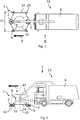
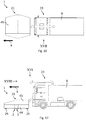
- the Figures 1 and 2 show a motor vehicle 23, with front cab and a rear suction 8.
- a device 1 for removing applied on paved traffic surfaces 22 applied order and / or attached to paved traffic areas 22 pollution via a mounting structure not shown is a device 1 for removing applied on paved traffic surfaces 22 applied order and / or attached to paved traffic areas 22 pollution via a mounting structure not shown .
- the device 1 is in the in the Fig. 1 and 2 illustrated working position arranged substantially horizontally to the traffic surface 22 and by means of the motor vehicle 23 to the traffic surface 22 movable.
- the device 1 has a chassis 24, wherein the chassis 24 in a direction of travel X of the device 1 has two front and two rear roller means 25 which rest on the traffic surface 22.
- the device 1 has two identically designed milling devices 2, the respective milling device 2 a rotatable injection element 3 with spray nozzles 4 for passing high-pressure liquid, in particular water, having.
- outlet openings of the spray nozzles 4 are directed in the working position of the device 1 in the direction of the traffic surface 22.
- the injection element 3 of the respective milling device 2 is rotatably mounted together with the spray nozzles 4 about an upright in the working position of the device 1 relative to the traffic surface 22 axis 5, 12 in a bearing structure 6 of the respective milling device 2.
- the injection element 3 of a milling device 2 about a second axis 5 and the injection element 3 of the further milling device 2 is rotatably mounted about a third axis 12 in a bearing structure 6 of the respective milling device 2.
- the one milling device 2 has a second drive 7 and the further milling device has a third drive 13 for driving the rotational movement of the respective injection element 3 about the respective axis 5, 12.
- the milling devices 2 are mounted rotatably together about a running in the working position of the device 1 relative to the traffic surface 22, outside the milling devices 2 extending first axis 10 in a bearing structure of the device 1, not shown.
- the device 1 has a first drive not shown in detail for driving the rotational movement of the milling devices 2 about the first axis 10.
- the rotational movement of the milling devices 2 about the first axis 10 is illustrated by an arrow 43.
- the two milling devices 2 are arranged opposite to the first axis 10 and symmetrically to the first axis 10.
- the milling devices 2 are fixedly connected to one another via the suction channel 9 designed as a tube, which extends radially inwards from the two milling devices 2 in the direction of the first axis 10 of the device 1 and together with the two milling devices 2 during operation of the device 1 Axis 10 of the device 1 rotates.
- the tube has a socket 11 which is formed coaxially with the first axis 10 and which in turn is connected to the suction device 8 of the truck 23 via a pipe.
- the first axis 10 of the device 1, the second axis 5 of a milling device 2, around which the injection element 3 with the spray nozzles 4 by means of the second drive 7 is rotatable, and the third axis 12 of the further milling device 2, by which the injection element 3 with the spray nozzles 4 of the further milling device 2 by means of a third drive 13 is rotatable, are formed parallel to each other and in the working position of the device 1 perpendicular to the traffic surface 22.
- a distance A of the respective axes 5, 12 of the milling devices 2 from the second axis 10 of the device 1 is approximately 5 times as large as a radius a Circle, which is formed by the rotation of the injection element 3 of the respective milling device 2 about the respective axis 5, 12.
- a working width d of the milling device 2 is formed by the injection element 3 rotating around the second axis 5 and the third axis 12, the working width d of the milling device is approximately twice the radius a of the circle, which is determined by the rotation of the injection element 3 respective milling device 2 about the respective axis 5, 12 is formed.
- a working width D of the device 1 of the working width d of the milling device 2 is added with twice the distance A of the second axis 5 and the third axis 12 from the first axis 10
- the working width D of the device 1 is about 6 times as large as a working width d of the respective milling device 2, which corresponds approximately to the dimension of the respective spray element 3 of the respective milling device 2.
- the working width D of the device 1 corresponds approximately to a dimension of the truck 23 perpendicular to the direction of travel X and parallel to the traffic surface 22nd
- the working width D of the device 1 is between 1.40 m and 4.20 m.
- a distance of a radially outermost point with respect to the first axis 10 of the injection element 3 of the respective milling device 2 from the first axis 10 of the device 1 is approximately equal to the distance A of the second axis 5 or the third axis 12 from the first axis 10 of the device 1 the radius a of the circle, which is formed by the rotation of the injection element 3 of the respective milling device 2 about the respective axis 5, 12.
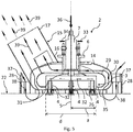
- Fig. 5 shows a detailed view of the milling device 2 according to Fig. 1 ,
- the milling device 2 has a bearing structure 6, wherein in this bearing structure 6 of the second drive 7, which is designed as a hydraulic motor, is mounted.
- An output shaft 31 of the second drive 7 is non-rotatably connected to the spray element formed as a spray bar 3, wherein the injection element 3 has a plurality of spray nozzles 4.
- the output shaft 31 is arranged, with reference to the working position of the device 1 or the milling device 2, upright to the traffic surface 22, specifically arranged perpendicular to the traffic surface 22.
- the injection element 3 is in turn arranged perpendicular to the output shaft 31 and rotates during operation of the device 1 about the second shaft 5 extending through the output shaft 31.
- the arrows 32 illustrate the direction of flow of the high pressure liquid / water through the spray element 3 to the spray nozzles 4.
- the arrow 33 illustrates, concerning the hydraulic drive 7, the input for pressure oil for driving the hydraulic motor 7 and the arrow 34 the output for the pressure oil from the hydraulic motor. 7
- an outer, hood-shaped housing 14 is mounted in the bearing structure 6 and connected thereto.
- an inner, hood-shaped housing 29 is mounted in the bearing structure 6 and connected thereto.
- the two housings 14, 29 are open to the traffic surface 22, wherein the outer housing 14, a flat opening surface 26 and the inner housing 29 forms a flat opening surface 35.
- the two opening surfaces 26, 35 are arranged perpendicular to the second axis 5 of the milling device 2 and thus, based on the working position of the milling device 2, parallel to the traffic surface 22. In this case, a distance of the opening surface 26 of the outer housing 14 is smaller than a distance of the opening surface 35 of the inner housing 29.
- the opening surface 26 of the outer housing 14 at a distance of 25 mm to the traffic surface 22 is arranged.
- the spray nozzles 4 are arranged at a distance from the traffic surface 22, which is slightly larger than the distance of the opening surface 26 of the outer housing 14 from the traffic surface 22. However, the distance of the spray nozzles 4 from the traffic surface 22 is less than the distance of the opening surface 35th of the inner housing 29 from the traffic area 22.
- the milling device 2 has a suction nozzle 15, wherein a first end 16 of the suction nozzle 15 is connected to the outer housing 14 and opens into the intermediate space 30 between the outer housing 14 and the inner housing 29. How the particular Fig. 4 can be seen, opens a second end 17 of the suction nozzle 15 in the suction channel 9 of the device 1, whereby by means of the suction device 8, which is in fluid communication with the suction channel 9, from the respective milling device 2 output liquid and removed order directly in the region of the respective Milling device 2 are sucked from the traffic area 22.
- the supply of the liquid to the injection element 3 of the milling device 2 takes place centrally along the second axis 5 through the hydraulic drive 7 through and is indicated by an arrow 36 in the Fig. 5 illustrated.
- a surrounding the outer housing 14 skirt 28 is disposed, wherein the skirt 28 in, relative to the outer housing 14 radially outwardly projecting, fasteners 37, specifically four fasteners 37 stored is. Consequently, the skirt 28 is radially spaced from the outer housing 14. Furthermore, the skirt 28 contacts the traffic surface 22 circumferentially. Since the skirt 28 is arranged radially spaced from the outer housing 14, an opening extending around the second axis 5 of the milling device 2 is formed between the skirt 28 and the outer housing 14. During operation of the device 1 suction air is sucked from the environment by this circumferential opening.
- the flow path of this suctioned from the environment suction air is indicated by the arrows 38 in the Fig. 5 illustrated.
- the inflow direction of the suction air between the skirt 28 and the outer housing 14 into the inner housing 29 is directed in the area of the opening surface 26 opposite to the radially outwardly directed centrifugal movement of the liquid discharged from the spray nozzles 4 and of the traffic area 22 by means of the liquid Order, so that sucked between the outer housing 14 and the inner housing 29 in the gap 30 suction air entrains the liquid and the removed order and this mixture is sucked along the arrows 39 through the suction 15 through means of the suction device 8 from the milling device 2.
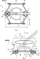
- the second embodiment has a with respect to the traffic surface 22 above the milling 2 arranged, the first axis 10 of the device 1 circumferentially enclosing suction ring 18th on, which forms a portion 18 of the suction channel 9.
- the suction ring 18 is formed parallel to the plane of rotation caused by the rotation of the milling devices 2 about the first axis 10 is formed, and has a facing in the direction of the traffic surface 22, the first axis 10 circumferentially enclosing and parallel to the plane of rotation, which is formed by the rotation of the milling means 2 about the first axis 10, formed opening 19 for sucking when milling the spray nozzles 4 issued liquid and milled order on.
- the suction ring 18 is connected via two angle-shaped fastening elements 40 to the chassis 24 and thus rotatably formed to the first axis 10 of the device 1.
- the suction nozzle 15 of the respective milling device 2 opens into the opening 19 of the suction ring 18, specifically the second end 17 of the suction nozzle 15 of the respective milling device 2 is arranged in the opening 19 of the suction ring 18 and the suction nozzle 15 passes through the opening 19.
- the two milling devices 2 rotate about the first axis 10 of the device 1, wherein the second end 17 of the respective suction nozzle 15 is displaced in the opening 19 of the suction ring 18 along a circumference, so that between the suction ring 18 and the suction nozzle 15th always there is a fluid connection.
- the liquid and saucester order are sucked through the suction nozzle 15 into the suction ring 18 and sucked off via a connected to the suction ring 18 suction tube 20, which in turn is connected to the suction device 8.
- sealing elements for sealing the opening 19 are arranged. These sealing elements are designed such that they close the opening 19 as close as possible, in the region in which the second end 17 of the suction nozzle 15 of the milling 2 is arranged, the second end 17 of the suction nozzle 15 passes through the sealing element, concretely displaced, so that only in the region of the suction ring 18, in which the second end 17 of the suction nozzle 15 is arranged, a suction takes place, however, in areas where no suction nozzle 15 is arranged, the sealing element sealingly closes the opening 19.
- the sealing element is preferably a flexible one or deformable sealing element, for example a flexible sealing lip or a sealing brush.
- the suction ring 18 has two with respect to the first axis 10 opposite outlet openings, wherein the two outlet openings open via a respective connecting pipe 41 in a common suction tube 20 of the suction channel 9, wherein the suction tube 20 is connected to the suction device 8.
- the two outlet openings are formed on the milling devices 2 facing away from the side of the suction ring 18.
- the two milling devices 2 are connected to each other in the second embodiment via a connecting strut 27, wherein the connecting strut 27 is a cylindrical bearing portion 42 for supporting the having two devices 2 in the bearing structure of the device 1.
- the bearing portion 42 is formed coaxially with the first axis 10 of the device 1 and on a side facing away from the traffic surface 22 of the connecting strut 27.
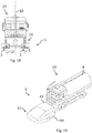
- the Fig. 16 to 19 show the second embodiment of the device 1 in a state connected to the motor vehicle 23, wherein a jacket portion 44 of a hood-shaped cover 21 of the device 1, the milling devices 2, the bearing structure of the device 1, the suction ring 18 and the chassis 24 of the device 1 with respect to the first Axis 10 circumferentially surrounds, thus covering the cover 21, the aforementioned components with respect to the first axis 10 radially outward. Furthermore, the cover 21 has a cover section 45, which is connected to the jacket section 44, the cover section 45 covering the aforementioned components of the device 1 on a side of the device 1 facing away from the traffic surface 22.
- the cover 21 the moving parts of the device 1 are protected from external influences, For example, in front of larger foreign bodies, which are located on the traffic surface 22, and also prevents people from entering the area of the rotating milling devices 2 or intervene in this area.
- the cover 21 is detachably connected to the other device 1. Furthermore, it is conceivable that the cover 21 has pivotable or hinged elements to allow easy access to the other components of the device 1 and / or to reduce the space requirement of the cover 21 for the purpose of transport.
- the two milling devices 2 describe a circular ring R due to the rotation about the first axis 10, wherein the axis 5 or 12 of the respective milling device 2 moves along the circumference of the circular ring R in the direction of the traffic surface 22 in the clockwise direction.
- the device 1 During operation of the device 1, it is moved in the working position of the device 1 parallel to the traffic surface 22 along the travel direction X.
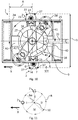
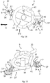
- an angular velocity of the milling device 2 rotating about the first axis 10 is varied such that in a first angular position the milling device 2 rotating about the first axis 10, in which an axis, specifically the axis of rotation 5, 12 of the injection element 3 respective milling device 2, aligned with the first axis 10 of the device 1 in the travel direction X of the device 1, the respective milling device 2 has a lower angular velocity than in a second angular position of the respective rotating milling device 2, wherein an angular difference ⁇ between the first angular position and the second Angular position is 90 °.
- Fig. 11 These different angular positions of the milling device 2 are in the Fig. 11 illustrated. Present in the Fig. 11 just one of the two milling facilities 2 illustrates. The further milling device 2 is arranged with respect to the first axis 10 of the device 1 opposite to a milling device 2.
- a circle which corresponds to the circular ring R described by the milling devices 2, divided into four circle segments, wherein the circle segments are each provided with Roman numerals, I, II, III and IV.
- the milling device 2 is in the first angular position in the circle segment I, which is formed in the travel direction X in front of the first axis 10 of the device 1.
- the angular velocity of the milling device 2 is less than in the two adjacent circle segments II, IV.
- the circle segment III which is opposite to the circle segment I with respect to the first axis 10, the angular velocity of the milling device 2 against the angular velocities in the on the circle segment III adjacent circle segments II, IV reduced.
- the angular velocity of the milling device 2 rotating about the first axis 10 varies periodically, a period of this period or an integral multiple of the period of this period being identical to a reciprocal of a rotational speed of the milling device 2 about the first Axis 10.
- the device 1 is shown with two different angular positions of the milling devices 2, wherein the rotating about the first axis 10 Components in one of the two angular positions are shown with dashed lines.
Landscapes
- Engineering & Computer Science (AREA)
- Architecture (AREA)
- Civil Engineering (AREA)
- Structural Engineering (AREA)
- Mechanical Engineering (AREA)
- Mining & Mineral Resources (AREA)
- Cleaning By Liquid Or Steam (AREA)
Priority Applications (2)
| Application Number | Priority Date | Filing Date | Title |
|---|---|---|---|
| DK17191267.8T DK3456881T3 (da) | 2017-09-15 | 2017-09-15 | Anordning og fremgangsmåde til fjernelse af materiale påført på befæstede færdselsarealer og/eller foreliggende snavs |
| EP17191267.8A EP3456881B1 (de) | 2017-09-15 | 2017-09-15 | Vorrichtung und verfahren zum entfernen von auf befestigten verkehrsflächen aufgebrachtem auftrag und/oder vorliegender verschmutzung |
Applications Claiming Priority (1)
| Application Number | Priority Date | Filing Date | Title |
|---|---|---|---|
| EP17191267.8A EP3456881B1 (de) | 2017-09-15 | 2017-09-15 | Vorrichtung und verfahren zum entfernen von auf befestigten verkehrsflächen aufgebrachtem auftrag und/oder vorliegender verschmutzung |
Publications (2)
| Publication Number | Publication Date |
|---|---|
| EP3456881A1 EP3456881A1 (de) | 2019-03-20 |
| EP3456881B1 true EP3456881B1 (de) | 2019-11-20 |
Family
ID=59895157
Family Applications (1)
| Application Number | Title | Priority Date | Filing Date |
|---|---|---|---|
| EP17191267.8A Active EP3456881B1 (de) | 2017-09-15 | 2017-09-15 | Vorrichtung und verfahren zum entfernen von auf befestigten verkehrsflächen aufgebrachtem auftrag und/oder vorliegender verschmutzung |
Country Status (2)
| Country | Link |
|---|---|
| EP (1) | EP3456881B1 (da) |
| DK (1) | DK3456881T3 (da) |
Families Citing this family (1)
| Publication number | Priority date | Publication date | Assignee | Title |
|---|---|---|---|---|
| CN110965513A (zh) * | 2019-12-04 | 2020-04-07 | 安徽爱瑞特新能源专用汽车股份有限公司 | 一种清扫车洗地机构 |
Family Cites Families (5)
| Publication number | Priority date | Publication date | Assignee | Title |
|---|---|---|---|---|
| DE60237601D1 (de) * | 2001-05-31 | 2010-10-21 | Tennant Co | Vorrichtung zur oberflächenreinigung |
| AT412189B (de) * | 2002-08-20 | 2004-11-25 | Walser & Co Ag | Verfahren zum reinigen von stark verschmutzten bodenflächen sowie dafür geeignetes bodenreinigungsgerät |
| US20070204889A1 (en) | 2006-03-03 | 2007-09-06 | Crocker James P | Articulable arm for a mobile mark removal system |
| DE102010023509A1 (de) * | 2010-06-11 | 2011-12-15 | Airmatic Gesellschaft für Umwelt und Technik mbH | Schwenkbare Reinigungsvorrichtung |
| EP3026180B1 (de) | 2014-11-26 | 2017-07-26 | Jan Cernota | Fräseinrichtung zum Entfernen von auf Verkehrsflächen aufgebrachtem Auftrag sowie Verfahren |
-
2017
- 2017-09-15 DK DK17191267.8T patent/DK3456881T3/da active
- 2017-09-15 EP EP17191267.8A patent/EP3456881B1/de active Active
Non-Patent Citations (1)
| Title |
|---|
| None * |
Also Published As
| Publication number | Publication date |
|---|---|
| EP3456881A1 (de) | 2019-03-20 |
| DK3456881T3 (da) | 2020-02-17 |
Similar Documents
| Publication | Publication Date | Title |
|---|---|---|
| EP2210982B1 (de) | Fahrbare Hochdruck-Reinigungsmaschine für Outdoor-Kunststoffböden und deren Anwendung | |
| EP3037585B1 (de) | Fräseinrichtung zum entfernen von auf verkehrsflächen aufgebrachtem auftrag sowie verfahren | |
| EP1160381A2 (de) | Anordnung zur Entfernung von Bremsspuren bzw, Reifengummiabrieb von einer Fahrbahn | |
| EP0773327B1 (de) | Verfahren und Vorrichtung zur Abreinigung einer durch umweltschädliche Medien kontaminierten und/oder in ihrer Griffigkeit beeinträchtigten Fahrbahn oder sonstigen Verkehrsfläche | |
| DE10359280A1 (de) | Sprühbeschichtungsvorrichtung | |
| DE10042042C1 (de) | Vorrichtung zur Reinigung einer Fahrbahn | |
| DE2257607A1 (de) | Verfahren und vorrichtung zur reinigung von oberflaechen | |
| DE2607385A1 (de) | Spruehvorrichtung | |
| EP3456881B1 (de) | Vorrichtung und verfahren zum entfernen von auf befestigten verkehrsflächen aufgebrachtem auftrag und/oder vorliegender verschmutzung | |
| WO2010105760A1 (de) | Kehrgerät für eine oberfläche | |
| DE4338450A1 (de) | Auffangvorrichtung für Overspray in Spritzkabinen | |
| DE9003356U1 (de) | Einrichtung zum Reinigen von Markierungen in Verkehrswegen | |
| DE202014009368U1 (de) | Fräseneinrichtung zum Entfernen von auf Verkehrsflächen aufgebrachtem Auftrag | |
| EP1312419A1 (de) | Vorrichtung und Verfahren zur Reinigung der Gitterroste einer Lackierkabine | |
| DE2145715A1 (de) | Kehrmaschine mit rotierenden Drehbürsten | |
| EP2690220B1 (de) | Kehrsaugmaschine mit einer Absaugung für einen Seitenbesen | |
| EP1215337A2 (de) | Saug-Kehraggregat | |
| EP2817104B1 (de) | Flächenreinigungskopf und strömungswiderstandselement für einen flächenreinigungskopf | |
| AT361533B (de) | Strassenreinigungsgeraet | |
| DE3816487A1 (de) | Vorrichtung zum reinigen der scheiben von automobil-neukarossen | |
| DE102017218304B4 (de) | System zur Reinigung von Reifen an landwirtschaftlich genutzten Straßenfahrzeugen | |
| DE102004011091A1 (de) | Einrichtung zur Reinhaltung der Oberfläche eines Sensors oder einer Sensorbaueinheit an einem Fahrzeug | |
| EP3195938B1 (de) | Modul zum abdecken von schutzbedürftigen abschnitten oder elementen auf befestigten oberflächen | |
| DE3315717C2 (de) | Gerät zur Herstellung eines verkehrssicheren Straßenzustandes bei Schnee- und Eisglätte | |
| DE2319884A1 (de) | Vorrichtung zum reinigen von reifen |
Legal Events
| Date | Code | Title | Description |
|---|---|---|---|
| PUAI | Public reference made under article 153(3) epc to a published international application that has entered the european phase |
Free format text: ORIGINAL CODE: 0009012 |
|
| STAA | Information on the status of an ep patent application or granted ep patent |
Free format text: STATUS: REQUEST FOR EXAMINATION WAS MADE |
|
| 17P | Request for examination filed |
Effective date: 20180518 |
|
| AK | Designated contracting states |
Kind code of ref document: A1 Designated state(s): AL AT BE BG CH CY CZ DE DK EE ES FI FR GB GR HR HU IE IS IT LI LT LU LV MC MK MT NL NO PL PT RO RS SE SI SK SM TR |
|
| AX | Request for extension of the european patent |
Extension state: BA ME |
|
| STAA | Information on the status of an ep patent application or granted ep patent |
Free format text: STATUS: EXAMINATION IS IN PROGRESS |
|
| 17Q | First examination report despatched |
Effective date: 20190325 |
|
| GRAP | Despatch of communication of intention to grant a patent |
Free format text: ORIGINAL CODE: EPIDOSNIGR1 |
|
| STAA | Information on the status of an ep patent application or granted ep patent |
Free format text: STATUS: GRANT OF PATENT IS INTENDED |
|
| INTG | Intention to grant announced |
Effective date: 20190711 |
|
| GRAS | Grant fee paid |
Free format text: ORIGINAL CODE: EPIDOSNIGR3 |
|
| GRAA | (expected) grant |
Free format text: ORIGINAL CODE: 0009210 |
|
| STAA | Information on the status of an ep patent application or granted ep patent |
Free format text: STATUS: THE PATENT HAS BEEN GRANTED |
|
| AK | Designated contracting states |
Kind code of ref document: B1 Designated state(s): AL AT BE BG CH CY CZ DE DK EE ES FI FR GB GR HR HU IE IS IT LI LT LU LV MC MK MT NL NO PL PT RO RS SE SI SK SM TR |
|
| REG | Reference to a national code |
Ref country code: GB Ref legal event code: FG4D Free format text: NOT ENGLISH |
|
| REG | Reference to a national code |
Ref country code: CH Ref legal event code: EP |
|
| REG | Reference to a national code |
Ref country code: IE Ref legal event code: FG4D Free format text: LANGUAGE OF EP DOCUMENT: GERMAN |
|
| REG | Reference to a national code |
Ref country code: DE Ref legal event code: R096 Ref document number: 502017002910 Country of ref document: DE |
|
| REG | Reference to a national code |
Ref country code: AT Ref legal event code: REF Ref document number: 1204320 Country of ref document: AT Kind code of ref document: T Effective date: 20191215 |
|
| REG | Reference to a national code |
Ref country code: CH Ref legal event code: NV Representative=s name: BOVARD AG PATENT- UND MARKENANWAELTE, CH |
|
| REG | Reference to a national code |
Ref country code: DK Ref legal event code: T3 Effective date: 20200212 |
|
| REG | Reference to a national code |
Ref country code: SE Ref legal event code: TRGR |
|
| REG | Reference to a national code |
Ref country code: NL Ref legal event code: FP |
|
| REG | Reference to a national code |
Ref country code: NO Ref legal event code: T2 Effective date: 20191120 |
|
| REG | Reference to a national code |
Ref country code: LT Ref legal event code: MG4D |
|
| PG25 | Lapsed in a contracting state [announced via postgrant information from national office to epo] |
Ref country code: BG Free format text: LAPSE BECAUSE OF FAILURE TO SUBMIT A TRANSLATION OF THE DESCRIPTION OR TO PAY THE FEE WITHIN THE PRESCRIBED TIME-LIMIT Effective date: 20200220 Ref country code: FI Free format text: LAPSE BECAUSE OF FAILURE TO SUBMIT A TRANSLATION OF THE DESCRIPTION OR TO PAY THE FEE WITHIN THE PRESCRIBED TIME-LIMIT Effective date: 20191120 Ref country code: LT Free format text: LAPSE BECAUSE OF FAILURE TO SUBMIT A TRANSLATION OF THE DESCRIPTION OR TO PAY THE FEE WITHIN THE PRESCRIBED TIME-LIMIT Effective date: 20191120 Ref country code: LV Free format text: LAPSE BECAUSE OF FAILURE TO SUBMIT A TRANSLATION OF THE DESCRIPTION OR TO PAY THE FEE WITHIN THE PRESCRIBED TIME-LIMIT Effective date: 20191120 Ref country code: GR Free format text: LAPSE BECAUSE OF FAILURE TO SUBMIT A TRANSLATION OF THE DESCRIPTION OR TO PAY THE FEE WITHIN THE PRESCRIBED TIME-LIMIT Effective date: 20200221 |
|
| PG25 | Lapsed in a contracting state [announced via postgrant information from national office to epo] |
Ref country code: IS Free format text: LAPSE BECAUSE OF FAILURE TO SUBMIT A TRANSLATION OF THE DESCRIPTION OR TO PAY THE FEE WITHIN THE PRESCRIBED TIME-LIMIT Effective date: 20200320 Ref country code: HR Free format text: LAPSE BECAUSE OF FAILURE TO SUBMIT A TRANSLATION OF THE DESCRIPTION OR TO PAY THE FEE WITHIN THE PRESCRIBED TIME-LIMIT Effective date: 20191120 Ref country code: RS Free format text: LAPSE BECAUSE OF FAILURE TO SUBMIT A TRANSLATION OF THE DESCRIPTION OR TO PAY THE FEE WITHIN THE PRESCRIBED TIME-LIMIT Effective date: 20191120 |
|
| PG25 | Lapsed in a contracting state [announced via postgrant information from national office to epo] |
Ref country code: AL Free format text: LAPSE BECAUSE OF FAILURE TO SUBMIT A TRANSLATION OF THE DESCRIPTION OR TO PAY THE FEE WITHIN THE PRESCRIBED TIME-LIMIT Effective date: 20191120 |
|
| PG25 | Lapsed in a contracting state [announced via postgrant information from national office to epo] |
Ref country code: PT Free format text: LAPSE BECAUSE OF FAILURE TO SUBMIT A TRANSLATION OF THE DESCRIPTION OR TO PAY THE FEE WITHIN THE PRESCRIBED TIME-LIMIT Effective date: 20200412 Ref country code: EE Free format text: LAPSE BECAUSE OF FAILURE TO SUBMIT A TRANSLATION OF THE DESCRIPTION OR TO PAY THE FEE WITHIN THE PRESCRIBED TIME-LIMIT Effective date: 20191120 Ref country code: RO Free format text: LAPSE BECAUSE OF FAILURE TO SUBMIT A TRANSLATION OF THE DESCRIPTION OR TO PAY THE FEE WITHIN THE PRESCRIBED TIME-LIMIT Effective date: 20191120 Ref country code: ES Free format text: LAPSE BECAUSE OF FAILURE TO SUBMIT A TRANSLATION OF THE DESCRIPTION OR TO PAY THE FEE WITHIN THE PRESCRIBED TIME-LIMIT Effective date: 20191120 Ref country code: CZ Free format text: LAPSE BECAUSE OF FAILURE TO SUBMIT A TRANSLATION OF THE DESCRIPTION OR TO PAY THE FEE WITHIN THE PRESCRIBED TIME-LIMIT Effective date: 20191120 |
|
| REG | Reference to a national code |
Ref country code: DE Ref legal event code: R097 Ref document number: 502017002910 Country of ref document: DE |
|
| PG25 | Lapsed in a contracting state [announced via postgrant information from national office to epo] |
Ref country code: SM Free format text: LAPSE BECAUSE OF FAILURE TO SUBMIT A TRANSLATION OF THE DESCRIPTION OR TO PAY THE FEE WITHIN THE PRESCRIBED TIME-LIMIT Effective date: 20191120 Ref country code: SK Free format text: LAPSE BECAUSE OF FAILURE TO SUBMIT A TRANSLATION OF THE DESCRIPTION OR TO PAY THE FEE WITHIN THE PRESCRIBED TIME-LIMIT Effective date: 20191120 |
|
| PLBE | No opposition filed within time limit |
Free format text: ORIGINAL CODE: 0009261 |
|
| STAA | Information on the status of an ep patent application or granted ep patent |
Free format text: STATUS: NO OPPOSITION FILED WITHIN TIME LIMIT |
|
| REG | Reference to a national code |
Ref country code: DE Ref legal event code: R082 Ref document number: 502017002910 Country of ref document: DE Representative=s name: THUM, MOETSCH, WEICKERT PATENTANWAELTE PARTG M, DE Ref country code: DE Ref legal event code: R082 Ref document number: 502017002910 Country of ref document: DE Representative=s name: THUM & PARTNER THUM MOETSCH WEICKERT PATENTANW, DE Ref country code: DE Ref legal event code: R082 Ref document number: 502017002910 Country of ref document: DE Representative=s name: WUESTHOFF & WUESTHOFF, PATENTANWAELTE PARTG MB, DE Ref country code: DE Ref legal event code: R081 Ref document number: 502017002910 Country of ref document: DE Owner name: VOLKMANN & ROSSBACH GMBH & CO KG, DE Free format text: FORMER OWNER: CERNOTA, JAN, 56422 WIRGES, DE |
|
| 26N | No opposition filed |
Effective date: 20200821 |
|
| REG | Reference to a national code |
Ref country code: NO Ref legal event code: CHAD Owner name: VOLKMANN & ROSSBACH GMBH & CO. KG, DE |
|
| REG | Reference to a national code |
Ref country code: CH Ref legal event code: PUE Owner name: VOLKMANN AND ROSSBACH GMBH AND CO. KG, DE Free format text: FORMER OWNER: CERNOTA, JAN, DE |
|
| PG25 | Lapsed in a contracting state [announced via postgrant information from national office to epo] |
Ref country code: SI Free format text: LAPSE BECAUSE OF FAILURE TO SUBMIT A TRANSLATION OF THE DESCRIPTION OR TO PAY THE FEE WITHIN THE PRESCRIBED TIME-LIMIT Effective date: 20191120 Ref country code: PL Free format text: LAPSE BECAUSE OF FAILURE TO SUBMIT A TRANSLATION OF THE DESCRIPTION OR TO PAY THE FEE WITHIN THE PRESCRIBED TIME-LIMIT Effective date: 20191120 |
|
| REG | Reference to a national code |
Ref country code: GB Ref legal event code: 732E Free format text: REGISTERED BETWEEN 20201105 AND 20201111 |
|
| REG | Reference to a national code |
Ref country code: NL Ref legal event code: PD Owner name: VOLKMANN & ROSSBACH GMBH & CO. KG; DE Free format text: DETAILS ASSIGNMENT: CHANGE OF OWNER(S), ASSIGNMENT; FORMER OWNER NAME: CERNOTA, JAN Effective date: 20201210 |
|
| PG25 | Lapsed in a contracting state [announced via postgrant information from national office to epo] |
Ref country code: IT Free format text: LAPSE BECAUSE OF FAILURE TO SUBMIT A TRANSLATION OF THE DESCRIPTION OR TO PAY THE FEE WITHIN THE PRESCRIBED TIME-LIMIT Effective date: 20191120 |
|
| REG | Reference to a national code |
Ref country code: AT Ref legal event code: PC Ref document number: 1204320 Country of ref document: AT Kind code of ref document: T Owner name: VOLKMANN & ROSSBACH GMBH & CO. KG, DE Effective date: 20201218 |
|
| REG | Reference to a national code |
Ref country code: BE Ref legal event code: MM Effective date: 20200930 |
|
| PG25 | Lapsed in a contracting state [announced via postgrant information from national office to epo] |
Ref country code: LU Free format text: LAPSE BECAUSE OF NON-PAYMENT OF DUE FEES Effective date: 20200915 |
|
| PG25 | Lapsed in a contracting state [announced via postgrant information from national office to epo] |
Ref country code: FR Free format text: LAPSE BECAUSE OF NON-PAYMENT OF DUE FEES Effective date: 20200930 |
|
| PG25 | Lapsed in a contracting state [announced via postgrant information from national office to epo] |
Ref country code: BE Free format text: LAPSE BECAUSE OF NON-PAYMENT OF DUE FEES Effective date: 20200930 Ref country code: IE Free format text: LAPSE BECAUSE OF NON-PAYMENT OF DUE FEES Effective date: 20200915 |
|
| REG | Reference to a national code |
Ref country code: DE Ref legal event code: R082 Ref document number: 502017002910 Country of ref document: DE Representative=s name: THUM, MOETSCH, WEICKERT PATENTANWAELTE PARTG M, DE Ref country code: DE Ref legal event code: R082 Ref document number: 502017002910 Country of ref document: DE Representative=s name: THUM & PARTNER THUM MOETSCH WEICKERT PATENTANW, DE |
|
| PG25 | Lapsed in a contracting state [announced via postgrant information from national office to epo] |
Ref country code: TR Free format text: LAPSE BECAUSE OF FAILURE TO SUBMIT A TRANSLATION OF THE DESCRIPTION OR TO PAY THE FEE WITHIN THE PRESCRIBED TIME-LIMIT Effective date: 20191120 Ref country code: MT Free format text: LAPSE BECAUSE OF FAILURE TO SUBMIT A TRANSLATION OF THE DESCRIPTION OR TO PAY THE FEE WITHIN THE PRESCRIBED TIME-LIMIT Effective date: 20191120 Ref country code: CY Free format text: LAPSE BECAUSE OF FAILURE TO SUBMIT A TRANSLATION OF THE DESCRIPTION OR TO PAY THE FEE WITHIN THE PRESCRIBED TIME-LIMIT Effective date: 20191120 |
|
| PG25 | Lapsed in a contracting state [announced via postgrant information from national office to epo] |
Ref country code: MK Free format text: LAPSE BECAUSE OF FAILURE TO SUBMIT A TRANSLATION OF THE DESCRIPTION OR TO PAY THE FEE WITHIN THE PRESCRIBED TIME-LIMIT Effective date: 20191120 Ref country code: MC Free format text: LAPSE BECAUSE OF FAILURE TO SUBMIT A TRANSLATION OF THE DESCRIPTION OR TO PAY THE FEE WITHIN THE PRESCRIBED TIME-LIMIT Effective date: 20191120 |
|
| P01 | Opt-out of the competence of the unified patent court (upc) registered |
Effective date: 20230522 |
|
| REG | Reference to a national code |
Ref country code: CH Ref legal event code: U11 Free format text: ST27 STATUS EVENT CODE: U-0-0-U10-U11 (AS PROVIDED BY THE NATIONAL OFFICE) Effective date: 20251001 |
|
| PGFP | Annual fee paid to national office [announced via postgrant information from national office to epo] |
Ref country code: DK Payment date: 20250922 Year of fee payment: 9 Ref country code: DE Payment date: 20250919 Year of fee payment: 9 |
|
| PGFP | Annual fee paid to national office [announced via postgrant information from national office to epo] |
Ref country code: NO Payment date: 20250919 Year of fee payment: 9 |
|
| PGFP | Annual fee paid to national office [announced via postgrant information from national office to epo] |
Ref country code: NL Payment date: 20250922 Year of fee payment: 9 |
|
| PGFP | Annual fee paid to national office [announced via postgrant information from national office to epo] |
Ref country code: GB Payment date: 20250923 Year of fee payment: 9 |
|
| PGFP | Annual fee paid to national office [announced via postgrant information from national office to epo] |
Ref country code: AT Payment date: 20250918 Year of fee payment: 9 |
|
| PGFP | Annual fee paid to national office [announced via postgrant information from national office to epo] |
Ref country code: SE Payment date: 20250922 Year of fee payment: 9 |
|
| PGFP | Annual fee paid to national office [announced via postgrant information from national office to epo] |
Ref country code: CH Payment date: 20251001 Year of fee payment: 9 |