EP3457047A1 - Personalisierte luftreinigungsvorrichtung - Google Patents
Personalisierte luftreinigungsvorrichtung Download PDFInfo
- Publication number
- EP3457047A1 EP3457047A1 EP17191238.9A EP17191238A EP3457047A1 EP 3457047 A1 EP3457047 A1 EP 3457047A1 EP 17191238 A EP17191238 A EP 17191238A EP 3457047 A1 EP3457047 A1 EP 3457047A1
- Authority
- EP
- European Patent Office
- Prior art keywords
- air
- housing
- cleaning device
- fan
- personalized
- Prior art date
- Legal status (The legal status is an assumption and is not a legal conclusion. Google has not performed a legal analysis and makes no representation as to the accuracy of the status listed.)
- Granted
Links
Images






Classifications
-
- B—PERFORMING OPERATIONS; TRANSPORTING
- B01—PHYSICAL OR CHEMICAL PROCESSES OR APPARATUS IN GENERAL
- B01D—SEPARATION
- B01D46/00—Filters or filtering processes specially modified for separating dispersed particles from gases or vapours
- B01D46/0002—Casings; Housings; Frame constructions
-
- A—HUMAN NECESSITIES
- A61—MEDICAL OR VETERINARY SCIENCE; HYGIENE
- A61M—DEVICES FOR INTRODUCING MEDIA INTO, OR ONTO, THE BODY; DEVICES FOR TRANSDUCING BODY MEDIA OR FOR TAKING MEDIA FROM THE BODY; DEVICES FOR PRODUCING OR ENDING SLEEP OR STUPOR
- A61M16/00—Devices for influencing the respiratory system of patients by gas treatment, e.g. ventilators; Tracheal tubes
- A61M16/10—Preparation of respiratory gases or vapours
- A61M16/105—Filters
-
- F—MECHANICAL ENGINEERING; LIGHTING; HEATING; WEAPONS; BLASTING
- F24—HEATING; RANGES; VENTILATING
- F24F—AIR-CONDITIONING; AIR-HUMIDIFICATION; VENTILATION; USE OF AIR CURRENTS FOR SCREENING
- F24F8/00—Treatment, e.g. purification, of air supplied to human living or working spaces otherwise than by heating, cooling, humidifying or drying
- F24F8/10—Treatment, e.g. purification, of air supplied to human living or working spaces otherwise than by heating, cooling, humidifying or drying by separation, e.g. by filtering
-
- A—HUMAN NECESSITIES
- A61—MEDICAL OR VETERINARY SCIENCE; HYGIENE
- A61L—METHODS OR APPARATUS FOR STERILISING MATERIALS OR OBJECTS IN GENERAL; DISINFECTION, STERILISATION OR DEODORISATION OF AIR; CHEMICAL ASPECTS OF BANDAGES, DRESSINGS, ABSORBENT PADS OR SURGICAL ARTICLES; MATERIALS FOR BANDAGES, DRESSINGS, ABSORBENT PADS OR SURGICAL ARTICLES
- A61L9/00—Disinfection, sterilisation or deodorisation of air
- A61L9/015—Disinfection, sterilisation or deodorisation of air using gaseous or vaporous substances, e.g. ozone
- A61L9/04—Disinfection, sterilisation or deodorisation of air using gaseous or vaporous substances, e.g. ozone using substances evaporated in the air without heating
- A61L9/12—Apparatus, e.g. holders, therefor
- A61L9/122—Apparatus, e.g. holders, therefor comprising a fan
-
- B—PERFORMING OPERATIONS; TRANSPORTING
- B01—PHYSICAL OR CHEMICAL PROCESSES OR APPARATUS IN GENERAL
- B01D—SEPARATION
- B01D45/00—Separating dispersed particles from gases or vapours by gravity, inertia, or centrifugal forces
- B01D45/12—Separating dispersed particles from gases or vapours by gravity, inertia, or centrifugal forces by centrifugal forces
-
- B—PERFORMING OPERATIONS; TRANSPORTING
- B01—PHYSICAL OR CHEMICAL PROCESSES OR APPARATUS IN GENERAL
- B01D—SEPARATION
- B01D46/00—Filters or filtering processes specially modified for separating dispersed particles from gases or vapours
- B01D46/0002—Casings; Housings; Frame constructions
- B01D46/001—Means for connecting filter housings to supports
-
- B—PERFORMING OPERATIONS; TRANSPORTING
- B01—PHYSICAL OR CHEMICAL PROCESSES OR APPARATUS IN GENERAL
- B01D—SEPARATION
- B01D46/00—Filters or filtering processes specially modified for separating dispersed particles from gases or vapours
- B01D46/52—Particle separators, e.g. dust precipitators, using filters embodying folded corrugated or wound sheet material
- B01D46/521—Particle separators, e.g. dust precipitators, using filters embodying folded corrugated or wound sheet material using folded, pleated material
- B01D46/525—Particle separators, e.g. dust precipitators, using filters embodying folded corrugated or wound sheet material using folded, pleated material which comprises flutes
-
- F—MECHANICAL ENGINEERING; LIGHTING; HEATING; WEAPONS; BLASTING
- F24—HEATING; RANGES; VENTILATING
- F24F—AIR-CONDITIONING; AIR-HUMIDIFICATION; VENTILATION; USE OF AIR CURRENTS FOR SCREENING
- F24F1/00—Room units for air-conditioning, e.g. separate or self-contained units or units receiving primary air from a central station
- F24F1/0007—Indoor units, e.g. fan coil units
- F24F1/0071—Indoor units, e.g. fan coil units with means for purifying supplied air
-
- F—MECHANICAL ENGINEERING; LIGHTING; HEATING; WEAPONS; BLASTING
- F24—HEATING; RANGES; VENTILATING
- F24F—AIR-CONDITIONING; AIR-HUMIDIFICATION; VENTILATION; USE OF AIR CURRENTS FOR SCREENING
- F24F1/00—Room units for air-conditioning, e.g. separate or self-contained units or units receiving primary air from a central station
- F24F1/02—Self-contained room units for air-conditioning, i.e. with all apparatus for treatment installed in a common casing
-
- F—MECHANICAL ENGINEERING; LIGHTING; HEATING; WEAPONS; BLASTING
- F24—HEATING; RANGES; VENTILATING
- F24F—AIR-CONDITIONING; AIR-HUMIDIFICATION; VENTILATION; USE OF AIR CURRENTS FOR SCREENING
- F24F1/00—Room units for air-conditioning, e.g. separate or self-contained units or units receiving primary air from a central station
- F24F1/02—Self-contained room units for air-conditioning, i.e. with all apparatus for treatment installed in a common casing
- F24F1/04—Arrangements for portability
-
- F—MECHANICAL ENGINEERING; LIGHTING; HEATING; WEAPONS; BLASTING
- F24—HEATING; RANGES; VENTILATING
- F24F—AIR-CONDITIONING; AIR-HUMIDIFICATION; VENTILATION; USE OF AIR CURRENTS FOR SCREENING
- F24F13/00—Details common to, or for air-conditioning, air-humidification, ventilation or use of air currents for screening
- F24F13/20—Casings or covers
-
- F—MECHANICAL ENGINEERING; LIGHTING; HEATING; WEAPONS; BLASTING
- F24—HEATING; RANGES; VENTILATING
- F24F—AIR-CONDITIONING; AIR-HUMIDIFICATION; VENTILATION; USE OF AIR CURRENTS FOR SCREENING
- F24F13/00—Details common to, or for air-conditioning, air-humidification, ventilation or use of air currents for screening
- F24F13/28—Arrangement or mounting of filters
-
- F—MECHANICAL ENGINEERING; LIGHTING; HEATING; WEAPONS; BLASTING
- F24—HEATING; RANGES; VENTILATING
- F24F—AIR-CONDITIONING; AIR-HUMIDIFICATION; VENTILATION; USE OF AIR CURRENTS FOR SCREENING
- F24F3/00—Air-conditioning systems in which conditioned primary air is supplied from one or more central stations to distributing units in the rooms or spaces where it may receive secondary treatment; Apparatus specially designed for such systems
- F24F3/12—Air-conditioning systems in which conditioned primary air is supplied from one or more central stations to distributing units in the rooms or spaces where it may receive secondary treatment; Apparatus specially designed for such systems characterised by the treatment of the air otherwise than by heating and cooling
- F24F3/16—Air-conditioning systems in which conditioned primary air is supplied from one or more central stations to distributing units in the rooms or spaces where it may receive secondary treatment; Apparatus specially designed for such systems characterised by the treatment of the air otherwise than by heating and cooling by purification, e.g. by filtering; by sterilisation; by ozonisation
- F24F3/163—Clean air work stations, i.e. selected areas within a space which filtered air is passed
-
- F—MECHANICAL ENGINEERING; LIGHTING; HEATING; WEAPONS; BLASTING
- F24—HEATING; RANGES; VENTILATING
- F24F—AIR-CONDITIONING; AIR-HUMIDIFICATION; VENTILATION; USE OF AIR CURRENTS FOR SCREENING
- F24F6/00—Air-humidification, e.g. cooling by humidification
-
- F—MECHANICAL ENGINEERING; LIGHTING; HEATING; WEAPONS; BLASTING
- F24—HEATING; RANGES; VENTILATING
- F24F—AIR-CONDITIONING; AIR-HUMIDIFICATION; VENTILATION; USE OF AIR CURRENTS FOR SCREENING
- F24F8/00—Treatment, e.g. purification, of air supplied to human living or working spaces otherwise than by heating, cooling, humidifying or drying
- F24F8/80—Self-contained air purifiers
-
- F—MECHANICAL ENGINEERING; LIGHTING; HEATING; WEAPONS; BLASTING
- F24—HEATING; RANGES; VENTILATING
- F24F—AIR-CONDITIONING; AIR-HUMIDIFICATION; VENTILATION; USE OF AIR CURRENTS FOR SCREENING
- F24F9/00—Use of air currents for screening, e.g. air curtains
-
- A—HUMAN NECESSITIES
- A47—FURNITURE; DOMESTIC ARTICLES OR APPLIANCES; COFFEE MILLS; SPICE MILLS; SUCTION CLEANERS IN GENERAL
- A47C—CHAIRS; SOFAS; BEDS
- A47C21/00—Attachments for beds, e.g. sheet holders or bed-cover holders; Ventilating, cooling or heating means in connection with bedsteads or mattresses
- A47C21/04—Devices for ventilating, cooling or heating
- A47C21/042—Devices for ventilating, cooling or heating for ventilating or cooling
- A47C21/044—Devices for ventilating, cooling or heating for ventilating or cooling with active means, e.g. by using air blowers or liquid pumps
-
- A—HUMAN NECESSITIES
- A61—MEDICAL OR VETERINARY SCIENCE; HYGIENE
- A61L—METHODS OR APPARATUS FOR STERILISING MATERIALS OR OBJECTS IN GENERAL; DISINFECTION, STERILISATION OR DEODORISATION OF AIR; CHEMICAL ASPECTS OF BANDAGES, DRESSINGS, ABSORBENT PADS OR SURGICAL ARTICLES; MATERIALS FOR BANDAGES, DRESSINGS, ABSORBENT PADS OR SURGICAL ARTICLES
- A61L2209/00—Aspects relating to disinfection, sterilisation or deodorisation of air
- A61L2209/10—Apparatus features
- A61L2209/14—Filtering means
-
- A—HUMAN NECESSITIES
- A61—MEDICAL OR VETERINARY SCIENCE; HYGIENE
- A61M—DEVICES FOR INTRODUCING MEDIA INTO, OR ONTO, THE BODY; DEVICES FOR TRANSDUCING BODY MEDIA OR FOR TAKING MEDIA FROM THE BODY; DEVICES FOR PRODUCING OR ENDING SLEEP OR STUPOR
- A61M16/00—Devices for influencing the respiratory system of patients by gas treatment, e.g. ventilators; Tracheal tubes
- A61M16/0057—Pumps therefor
- A61M16/0066—Blowers or centrifugal pumps
-
- A—HUMAN NECESSITIES
- A62—LIFE-SAVING; FIRE-FIGHTING
- A62B—DEVICES, APPARATUS OR METHODS FOR LIFE-SAVING
- A62B23/00—Filters for breathing-protection purposes
-
- B—PERFORMING OPERATIONS; TRANSPORTING
- B01—PHYSICAL OR CHEMICAL PROCESSES OR APPARATUS IN GENERAL
- B01D—SEPARATION
- B01D2259/00—Type of treatment
- B01D2259/45—Gas separation or purification devices adapted for specific applications
- B01D2259/4541—Gas separation or purification devices adapted for specific applications for portable use, e.g. gas masks
-
- F—MECHANICAL ENGINEERING; LIGHTING; HEATING; WEAPONS; BLASTING
- F24—HEATING; RANGES; VENTILATING
- F24F—AIR-CONDITIONING; AIR-HUMIDIFICATION; VENTILATION; USE OF AIR CURRENTS FOR SCREENING
- F24F13/00—Details common to, or for air-conditioning, air-humidification, ventilation or use of air currents for screening
- F24F13/20—Casings or covers
- F24F2013/205—Mounting a ventilator fan therein
-
- F—MECHANICAL ENGINEERING; LIGHTING; HEATING; WEAPONS; BLASTING
- F24—HEATING; RANGES; VENTILATING
- F24F—AIR-CONDITIONING; AIR-HUMIDIFICATION; VENTILATION; USE OF AIR CURRENTS FOR SCREENING
- F24F2221/00—Details or features not otherwise provided for
- F24F2221/38—Personalised air distribution
Definitions
- the invention relates to a personalized air cleaning device according to the preamble of claim 1.
- Another disadvantage of this known technique is that debris and bacteria can settle in the device itself and in the long air supply hoses, which lead to a contamination of the supplied air.
- the invention is therefore the object of developing a personalized air cleaning device of the type mentioned so that an easy handling of the device and improved reliability are guaranteed.
- the invention is characterized by the technical teaching of claim 1.
- the invention also describes the application of room air conditioning.
- a personalized air purifier is beneficial.
- a personalized air purifier can be more efficient, energy efficient and quieter than air purifiers that try to purify all the air in an interior and often only contribute to a small improvement in the room air because they do not purify enough room air to keep up with the constant air pollution sources it purifies only as much air as is necessary to purify the user's immediate breathing zone.
- the unit can be positioned very close to the outlet and at the optimum angle of the user's breathing zone, the clean air from the personalized air cleaner does not mix with pollutants from pollution sources in the room. The user can breathe extremely clean air.
- the personalized air purification device in the design as a tabletop device has a housing that corresponds in size and shape about a - used for sports competitions - Discus disc, as it is known as a throwing device in sports.
- Characteristic of this form is that the air conditioning and air discharge takes place in a relatively small, rotationally symmetrical housing, so that for the first time offers the possibility to form such an air cleaning device as a tabletop device and set up with a lightweight stand on a table.
- a personalized air cleaning device in the form of a disc-shaped housing, which is preferably rotationally symmetrical, now offers the possibility that the device can be rotated on a table stand in any manner about a horizontal axis of rotation, so as a targeted exposure to allow the body of the user.
- the central transverse region of the approximately disk-shaped housing body spans a radial plane which extends from the center of the device radially outwards in the direction of the outer circumference.
- this radial plane now both the Lufteinsaug Complex and the Heilausblas Complex are aligned and without axial offset from each other, resulting in a small width.
- the blow-off air stream flows in a laminar manner and is turbulence-free and is adjustable in its blow-out strength in order to ensure that the user does not perceive a direct air flow directed directly at the face (and the respiratory tract) as disturbing.
- optically perceptible lighting elements are present on or in the blower outlet, which light up only when an exhaust air flow is actually generated.
- the invention is not limited to the formation of the housing as a tabletop device.
- the device can be used in the same or a larger diameter version as a wall unit. It is then hung on a wall stand and can also be designed to be rotatable about a horizontal axis on this wall stand.
- the invention provides that the disk-shaped air cleaning device according to the invention is also attached to a car seat holder on the backrest of the front seat of a motor vehicle and is also mounted there pivotable or rotatable.
- an additional device for scenting the blow-out air flow can be provided.
- an ionizer is arranged to allow the delivery of ionized air.
- the invention relates to a personalized air cleaning device having a housing, which has at least one Nursingeinsaug Colour for sucking air into the housing and at least one Heilausblas Scheme for blowing the air from the housing, wherein in the housing at least one, to a fan rotation axis rotatable fan wheel of the air cleaning device and at least an intake air filter of the air cleaning device for filtering the air sucked through the Nursingeinsaug Colour are arranged and the fan wheel, the air in the operation of the air cleaning device at least in a direction parallel to the fan rotation axis in the fan and sucks in at least one direction radially away from the fan wheel radially away from the fan wheel.
- the fan wheel is the component of the air cleaning device with which the air movement for sucking the air through the Lufteinsaug Colour, for transporting the air through the housing and for blowing the air through the Heilausblas Scheme out of the housing is generated. It is a wheel which rotates in a rotation direction around the fan rotation axis during operation of the air cleaning device.
- the fan wheel in preferred embodiments, has a plurality of air vanes which are arranged, preferably spaced, from the fan rotation axis, or extend at least in that direction.
- These air blades can be arranged on a base surface of the fan wheel and protrude from this base in the direction parallel to the axis of rotation, preferably orthogonal.
- the base is arranged in preferred embodiments orthogonal to the fan rotation axis.
- the air blades viewed from the fan rotation axis, are aligned at an angle to the radial direction.
- the fan or the fan wheel is designed as a so-called, backward curved centrifugal fan.
- the fan wheels of the air cleaning devices provide for the fan wheel to suck the air into the fan wheel at least in one direction parallel to the fan rotation axis during operation of the air cleaning device and to blow away from the fan wheel in at least one direction radially to the fan rotation axis.
- Air purification devices according to the invention can be used as a room air purifier to clean the air in a room.
- Preferred embodiments of air cleaning devices according to the invention provide, however, that the purified air is blown in a targeted direction or in a directional range.
- Such air cleaning devices according to the invention can also be used as so-called respiratory zone air purifiers, which can be used, for example, to blow a person specifically cleaned air into the breathing zone.
- the air purifier is assigned to a specific person and is thus personalized.
- Preferred embodiments of the invention provide that, viewed in a plan view from the direction parallel to the fan rotation axis, the intake air filter surrounds the interior space in which the fan wheel is arranged only incompletely.
- a blow-out space is arranged in the section left free from the intake air filter, into which the fan wheel blows the air on its way towards the air blow-out area of the housing during operation.
- Blow-out air filters may be arranged in the blow-out space according to the invention.
- variants of an air cleaning device according to the invention are also conceivable in which the exhaust air filter in the blow-out space is dispensed with.
- blow-out space and the air intake area are arranged in the same plane. This is the advantage of a hitherto unknown reduction in height connected.
- the air intake region of the housing is delimited by two imaginary mutually parallel boundary planes and one or the blow-out space into which the fan wheel injects the air during operation on the way to the air blow-out region of the housing, and / or or the Heilausblas Scheme the housing is at least partially, preferably completely, is arranged between the parallel boundary planes or are.
- the boundary planes are preferably orthogonal or normal to the fan rotation axis.
- preferred variants of the invention provide that the intake air filter does not completely enclose the interior space in which the fan wheel is at least partially disposed.
- the intake air filter is C-shaped.
- the term C-shaped design is to be understood broadly. The C can be bent or angular etc. These are ultimately forms of the intake air filter, which surround the said interior but are not completely closed circumferentially.
- Preferred variant of the invention provide that between the intake air filter and the fan wheel, a barrier wall for deflecting the air sucked through the intake air filter toward the fan wheel is arranged.
- the barrier wall is advantageously also arranged in the interior surrounded by the intake air filter.
- the barrier wall With the barrier wall, it is possible that an air flow of the sucked by the fan wheel through the Lufteinsaug Colour in the housing air relative to the fan rotation axis in the radial direction into the Einsaug Kunststofffilter and then at least also in directions parallel to the fan rotation axis around the barrier wall to the fan wheel.
- the barrier wall advantageously has an opening for blowing in the air from the fan wheel into or a blow-out space. The air is thereby blown by the fan wheel in at least one direction radially to the fan rotation axis in the blow-out.
- the barrier wall can partially enclose a receiving space for the fan wheel.
- the fan wheel is arranged eccentrically in the receiving space. This means that the fan wheel is arranged in certain areas closer to the barrier wall, as in other areas of the receiving space.
- the receiving space for the fan wheel is, advantageously together with the barrier wall, at least partially in the interior, which is at least partially surrounded by the intake air filter.
- the housing in a view from the direction parallel to the fan rotation axis has a circular outer contour.
- the housing can have a disc-shaped outer contour.
- the air intake area and / or the air outlet area may be arranged, viewed from the fan rotation axis, at the radially outer edge of the housing.
- the Lufteinsaug Society and the Heilausblashaft seen from the axis of rotation, in mutually different areas of the radially outer edge of the Housing are arranged.
- Both in Vietnameseeinsaug GmbH and in Heilausblas Symposium can be arranged in each case a sequence of lamellae. Air can be sucked into the housing between the fins in the air intake area. Between the louvers in Heilausblas Symposium the air can be blown out of the housing.
- the lamellae can be arranged at an angle relative to the radial direction from the fan rotation axis both in the air intake region and in the air discharge region.
- FIG. 1 is a side perspective view of the air cleaning device 1 according to the invention in the form of a rotationally symmetrical circular cylindrical housing 2, which has two mutually symmetrical half-shells 20, which form a central annular groove 40 between them in the middle, preferably the annular groove 40 recessed circumferentially disposed in the housing, as this for example FIGS. 8 and 9 is removable.
- FIGS. 1 and 2 Can now be attached to the air outlet 4 a Ausblasstutzen 30, which has an approximately trumpet-shaped shape and in its front region has a Ausströmgitter 31 which a laminar air flow over the blow-out stream 32 (see FIG. 3 ) generated.
- the z in the direction of arrow 37 z. B. can be directed against the head portion 33 of a user 49.
- blow-out air stream 32 is directed directly into the breathing zone of the user 49, so that the user 49 receives predominantly purified blow-out air from the blow-out nozzle 30, which is e.g. B. of toxins, foreign odors, plant and grass pollen and the like is cleaned.
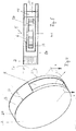
- FIG. 3 also shows that the air cleaning device is approximately disc-shaped in the manner of a Discusis, as used for example as a disc in athletics. Also the size ratios of the execution after the FIGS. 1 to 3 match those of a disc.
- FIGS. 4 and 5 show more details of the device after the FIGS. 1 to 3 , and it is clearly seen that in a rotationally symmetrical housing 2 according to FIG. 4 the shipseinsaug Society 3 extends approximately C-shaped around the outer periphery of the housing 2 and therefore in this large area an adapted C-shaped Einsaug Kunststofffilter 7 (see FIG. 7 and FIG. 14 ) can be arranged so that a high volume flow can be filtered by a suction filter 7 having a large filter surface.
- the inventive merit of the invention is to put the air intake in the peripheral region on the outer circumference of the device to directly behind the housing in a large area preferably designed as a folded filter-suction air filter 7 can, which sucks the intake air over a wide peripheral region and a conical generated to the fan wheel 6 tapered air flow in the housing.
- FIG. 5 Further details of the arrangement can be seen, wherein it is important that both the Lufteinsaug Club 3 is located on the outer circumference of the housing 2 in the region of the aforementioned radial annular groove 40, and the Heilausblas Scheme. 4
- FIG. 6 shows the basic structure of the housing 2, where it can be seen that the two substantially identically formed half-shells 20 receive between them an air guide housing 38, in whose central interior the fan wheel 6 is received, which is driven to rotate about the fan rotation axis 5.
- the Luftausblas Complex 4 of the air guide housing 38 is arranged so that said parts are arranged in the same plane 39.
- FIGS. 7 to 10 further details of the structure of the housing 2 with the air-conducting elements.
- the housing 2 has a circular outer contour.
- the housing 2 has a disc-shaped outer contour.
- the Lufteinsaug Scheme 3 and / or the Heilausblas Scheme 4 are arranged on the radially outer edge 17 of the housing 2. Together they form a surrounding area around the housing 2 of openings for the air inlet and outlet into and out of the housing.
- this can be seen on the lamellae 18 and 19, which are located in the air intake region 3 and in the air outlet region 4, as is the case in particular in the section along the section line AA Fig. 12 in Fig. 13 can be seen.
- Fig. 12 are also the two mutually parallel boundary planes 13 located. Both the Heileinsaug Colour 3 and the Heilausblas Scheme 4 of this embodiment are bounded by these mutually parallel boundary planes 13.
- the two are imaginary Limiting planes 13 are arranged normal or orthogonal to the direction 8 and thus also to the longitudinal course of the fan rotation axis 5.
- the blow-out space 11 is arranged, into which the fan wheel 6 blows the air on its way towards the air blow-off area 4 of the housing 2 during operation.
- a blow-out air filter 12 In the blow-out 11 is in the first embodiment, as is particularly good in Fig. 13 can be seen, arranged a blow-out air filter 12.
- the intake air filter 7 of this embodiment is C-shaped. Between the inlet air filter 7 and the fan wheel 6 there is the barrier wall 14. With this, the air sucked in through the suction air filter 7 is deflected on the way to the fan wheel 6, as will be described in more detail below with reference to FIG Figure 15 and 16 is shown.
- Fig. 13 the directions 9 are shown radially to the fan rotation axis 5.
- the air to be cleaned in the Lucaseinsaug Hoch 3 is sucked by means of the rotating about its fan rotation axis 5 fan wheel 6.
- the sucked air penetrates the spaces between the fins 18 of the housing 2 in the Heileinsaug Scheme 3 and then flows in the radial direction 9 in the Einsaug povertyfilter 7.
- the barrier wall 14 then deflects the so-aspirated air on the way from Einsaugluftfilter 7 towards the fan 6.
- the air is then sucked in direction 8 parallel to the fan rotation axis 5 in the fan wheel 6 and blown in the direction 9 radially outward from the fan wheel 6 through an opening 15 in the barrier wall 14 into the blow-out 11.
- the air leaves the blow-out 11 in this gamericsbei then through the blow-out air filter 12 and through the fins 19 of the Heilausblas Schemes 4 therethrough.
- Fig. 13 is also good to see that both the fins 18 and the fins 19 are arranged in this embodiment, each angled to the radial direction 9.
- the barrier wall 14 encloses the receiving space 16, in which the fan wheel 6 is located partially.
- the fan wheel 6 is arranged eccentrically in this receiving space 16. It is thus on the one hand, namely in Fig. 13 lower left, closer to the barrier wall 14 than on the opposite side, in Fig. 13 top left.
- the fan wheel 6 rotates about its fan rotation axis 5. It is for this purpose of the in the Fig. 15 and 16 drawn fan motor 23 rotated. The direction of rotation 29 of the fan wheel 6 in operation is in Fig. 13 located.
- the fan wheel 6 or the fan is a so-called radial fan with backward curvature. This is also well recognized by the shape of the air blades 21. These are arranged on a base surface 22 of the fan wheel 6 and extend in a direction 8 parallel to the fan rotation axis 5. In a variant not shown in the drawing, the fan can also be designed as a forward curved radial fan.
- filters can be used.
- they may be paper filters, in particular folded paper filters, to filter out dust or particles from the air. But it may also be other porous materials with a corresponding air cleaning effect.
- Both types of filter can be used e.g. also have activated carbon or the like to eliminate germs and the like.
- Fig. 14 shows a section in the sectional plane BB according to Fig. 12 ,
- This sectional plane BB runs parallel to the sectional plane AA in a region in which neither the barrier wall 14 nor the air blades 21 of the fan wheel 6 are located, ie in the region in which the air sucked through the intake air filter 7 the barrier wall 14 can pass.
- exhaust air filter 12 is no longer present in this sectional plane BB.
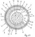
- Fig. 15 shows a section through the air cleaning device 1 of this first embodiment, in which Fig. 13 Plotted cutting plane CC. This runs parallel to the fan rotation axis 5 and cuts the intake air filter 7 twice.
- Fig. 16 shows a section through this air cleaning device 1 in the also in Fig. 13 Plotted cutting plane DD. It is, however, arranged orthogonal to the cutting plane CC and cuts on the one hand the Lufteinsaug Club 3 with the Einsaug Kunststofffilter 7 and on the other hand but also the Heilausblas Scheme 4 and arranged here in this embodiment exhaust air filter 12th
- FIGS Fig. 15 and 16 Based on Fig. 15 and 16 the air flow in the housing 2 is particularly easy to follow.
- the airflow 24 is schematized in the form of arrows in FIGS Fig. 15 and 6 located.
- Fig. 15 and 16 can be clearly seen from the arrows 24 symbolizing the air flow, that the air is sucked from the outside in the Lucaseinsaug Society 3 in the radial direction 9 toward the fan rotation axis 5 in the Einsaugluftfilter 7.
- the barrier wall 14 takes place then within the housing 2, a deflection of the air flow 24 of the sucked air with components of movement in directions 8 parallel to the fan rotation axis 5.
- the sucked air has passed the barrier wall 14, it is then in the direction 8 parallel to the fan rotation axis 5 in sucked in the fan wheel 6.
- the fan wheel 6, which rotates in the direction of rotation 29 by means of the fan motor 23, then presses with its air blades 21 the air through the opening 15 in the barrier wall 14 in the direction 9 radially outward into the blow-out space 11. In this is located, as in Fig. 16 Through this, the air is blown from the fan wheel 6 in the radial direction 9 to the outside, ie away from the fan rotation axis 5, so that it leaves the housing 2 through the Heilausblas Symposium 4.
- the air to be cleaned is sucked into the housing 2 in radial directions 9, then deflected in a direction parallel to the fan rotation axis 5 around the barrier wall 14 and sucked into the fan wheel 6 and from there in radial directions 9 to the outside of the fan rotation axis. 5 blown out of the housing 2 through the blow-out 11 and the air outlet 4 as purified air again.
- the Fig. 18 shows you one Fig. 13 analogue cut.
- the cut according to Fig. 17 corresponds to the section according to Fig. 16 of the first embodiment.
- the purge 11 of this embodiment is empty, so that the blown out of the housing 2 through the Heilausblas Scheme 4 air in the blow-out 11 is not cleaned again by means of a Ausblas Kunststofffilters 12 additionally.
- a scenting device may additionally be arranged in the area of this blow-off air filter 12.
- Fig. 7 the fan wheel 6 with its fan rotation axis 5 and the suction air filter 7 of the first two embodiments are shown without the other components of the air purification device 1.
- the fan wheel 6 is arranged in the interior 10 partially surrounded by the intake air filter 7.
- Fig. 8 to 10 show different variants of how the air purification device 1 can be set up or held in operation.
- a stand 26 is attached laterally to one of the half-shells 20 of the housing 2.
- this base 26 can also be equal to a power connection for the fan motor 23 integrated.
- Fig. 9 shows a variant in which the housing 2 of the air cleaning device 1 is placed into a corresponding base 26.
- an adapter arm 28 is attached laterally to one of the half shells 20. This can be attached with any brackets to a variety of carriers. In all embodiments, it is advantageous to detachable connections between the feet 26 and the adapter arm 28 and the housing second
- a shaping element 25 is releasably attached to the Heilausblas Grade 4, with which the blown through the Heilausblas Scheme 4 cleaned air can be targeted even better targeted to a specific area. This is particularly useful when the air purification device 1 is used as a breathing air purifier to direct targeted purified air into the breathing area of a person.
- This shaping element 25 is formed as a curved, the outer circumference of the housing 2 adapted Ausblasstutzen 30.
- the outflow end is formed by a number of curved fins which provide a laminar blow-off airflow 32 into the respiratory zone of the user 49 (see Figs Fig. 3 ) judge.
- the Ausblas Kunststoffstrom 32 is low turbulence and is therefore not or barely perceived by the user 49. It is therefore additionally provided that one or more colored LEDs are arranged in the air outlet region 4 and / or on the outlet nozzle 30, which display the airflow intensity and / or its composition (scenting, ionization) visually perceptible.
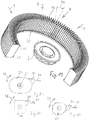
- FIG. 19 shows a preferred embodiment of a Einsaug Kunststofffilters 7, which consists of a folded filter, wherein a number of filter pleats 43 sealed on a plate-shaped C-shaped ring carrier 42 are applied and the upper side of the filter pleats are fixed by a filter all folds inside connecting retaining ring 45.
- the intake air filter 7 is designed as a pleated filter and the filter pleats 43 open conically outward in a cone angle 44.
- intake air filters may be used, in particular intake air filters which are interrupted over their curved length. They then form no continuous C-shaped body, but are sector-shaped composed of individual curved elements, the total then form a C-shaped intake air filter 7.
- FIGS. 20 to 22 show schematically different from the housing shape of the housing 2 different housing forms 2a, 2b, 2c.
- FIG. 20 shows that the rotationally symmetrical housing 2 after the FIGS. 1 to 3 may also be formed as an oval housing 2a, which is mounted about the horizontal axis of rotation 50 in the arrow directions 48 rotatably mounted on a suitable stand, a holder or the like.
- FIG. 21 shows that the housing 2b can also be of square construction and in FIG. 22 It is shown that the housing 2c can also have a polygonal cross-section.
- the housing 2, 2a-2c is approximately disc-shaped, d. H.
- the width 47 has a relation to the diameter of the device in the range between 1: 2 to 1:10.
- FIG. 3 shows the connection with the FIGS. 20 to 22 in that such a housing 2, 2a-2c can set up a suitable base 26 on the footprint 35 of a table 36. It can also be fastened with a wall mount on a building wall rotatable about the axis of rotation 50 or it can be arranged with a suitable holder in a motor vehicle.
Landscapes
- Engineering & Computer Science (AREA)
- Chemical & Material Sciences (AREA)
- Combustion & Propulsion (AREA)
- Mechanical Engineering (AREA)
- General Engineering & Computer Science (AREA)
- Health & Medical Sciences (AREA)
- Chemical Kinetics & Catalysis (AREA)
- General Health & Medical Sciences (AREA)
- Veterinary Medicine (AREA)
- Public Health (AREA)
- Animal Behavior & Ethology (AREA)
- Life Sciences & Earth Sciences (AREA)
- Hematology (AREA)
- Heart & Thoracic Surgery (AREA)
- Biomedical Technology (AREA)
- Emergency Medicine (AREA)
- Anesthesiology (AREA)
- Pulmonology (AREA)
- Epidemiology (AREA)
- Filtering Of Dispersed Particles In Gases (AREA)
- Disinfection, Sterilisation Or Deodorisation Of Air (AREA)
Abstract
Description
- Die Erfindung betrifft eine personalisierte Luftreinigungsvorrichtung nach dem Oberbegriff des Patentanspruches 1.
- Besonders sensitive Personen, die viel Zeit an einem Platz in Großraumbüros und in anderen Räumen verbringen, haben vermehrt das Bedürfnis, Luft zu atmen, die gereinigt ist und/oder beduftet sein kann.
- Es besteht daher ein Bedürfnis, die Luft in Räumen noch zusätzlich zu reinigen und/oder zu beduften und jeweils einem Benutzer personalisiert zuzuführen. Dies auch deshalb, weil Klimaanlagen keine völlige Allergiefreiheit (Freiheit von Blüten- und Gräserpollen) und Geruchsfreiheit der zugeführten Raumluft erreichen können. Des Weiteren deshalb, weil Raumluftreiniger, sofern vorhanden, nicht die gesamte Raumluft in einem Raum, aufgrund ständig aktiver Luftverschmutzungsquellen, vollständig reinigen können.
- Mit dem Gegenstand der
US 9,375,547 B2 US 9,144,697 B2 - Aus der
US 8,414,671 B2 ist es ferner bekannt, den Kopf des Benutzers in einem zentralen kastenförmigen Gerät zu lagern, um gezielt dem Benutzer einen auf ihn abgestimmten gereinigten Luftstrom zuzuführen. - Nachteil der genannten Druckschriften ist die Notwendigkeit der Anordnung von eigenen Luftzuführvorrichtungen, die den Benutzer möglicherweise in seiner Bewegungsfreiheit einschränken und weiterer Nachteil ist die schwierige Handhabung, denn die gereinigte Luft wird von einem auf den Boden aufgestellten Gerät erzeugt, welches über einen relativ langen Schlauch mit der Luftzuführungshutze verbunden ist.
- Weiterer Nachteil dieser bekannten Technik ist, dass sich im Gerät selbst und in den langen Luftzuführungsschläuchen Schmutzteile und Bakterien absetzen können, die zu einer Verkeimung der zugeführten Luft führen.
- Der Erfindung liegt deshalb die Aufgabe zugrunde, eine personalisierte Luftreinigungsvorrichtung der eingangs genannten Art so weiterzubilden, dass eine leichte Handhabbarkeit des Gerätes und eine verbesserte Betriebssicherheit gewährleistet sind.
- Zur Lösung der gestellten Aufgabe ist die Erfindung durch die technische Lehre des Anspruches 1 gekennzeichnet.
- Neben der Notwendigkeit einer personalisierten Klimatisierung beschreibt die Erfindung jedoch auch die Anwendung einer Raumluftklimatisierung.
- Wo immer eine Person für längere Zeit an einem definierten Platz, wie z.B. Arbeitstisch oder im Bett Zeit verbringt und die Luft nicht frei von Luftfremdstoffen ist, ist eine personalisierte Luftreinigungsvorrichtung von Vorteil.
- Gegenüber Raumluftreinigern, die versuchen die ganze Luft in einem Innenraum zu reinigen und oft nur zu einer kleinen Verbesserung der Raumluft beitragen, da sie nicht genug Raumluft reinigen, um mit den ständigen Luftverschmutzungsquellen mitzuhalten, kann eine personalisierte Luftreinigungsvorrichtung wirksamer, stromsparender und leiser sein, da sie nur so viel Luft reinigt wie notwendig ist, um die unmittelbare Atemzone des Nutzers zu reinigen.
- Dadurch, dass das Gerät sehr nahe an und der Auslass im optimalen Winkel der Atemzone des Nutzer positioniert werden kann, vermischt sich die saubere Luft vom personalisierten Luftreiniger nicht mit Schadstoffen aus Schadstoffquellen im Raum. Der Nutzer kann extrem sauberer Luft atmen.
- Merkmal der Erfindung ist deshalb, dass die personalisierte Luftreinigungsvorrichtung in der Ausführung als Tischgerät ein Gehäuse aufweist, das in den Abmessungen und der Formgebung etwa einer - für Sportwettbewerbe verwendeten - Diskusscheibe entspricht, wie sie als Wurfgerät im Sport bekannt ist.
- Kennzeichnend für diese Form ist, dass die Luftaufbereitung und Luftabgabe in einem relativ kleinen, rotationssymmetrischen Gehäuse stattfindet, so dass sich erstmals die Möglichkeit bietet, eine solche Luftreinigungsvorrichtung als Tischgerät auszubilden und mit einem leichtgewichtigen Ständer auf einem Tisch aufzustellen.
- Weiteres Merkmal der Erfindung ist, dass eine solche personalisierte Luftreinigungsvorrichtung in Form eines scheibenförmigen Gehäuses, das bevorzugt rotationssymmetrisch ausgebildet ist, nunmehr die Möglichkeit bietet, dass das Gerät auf einem Tischständer in beliebiger Weise um eine horizontale Rotationsachse gedreht werden kann, um so eine gezielte Anstrahlung des Körpers des Benutzers zu ermöglichen.
- Somit wird ein leicht handhabbares Gerät mit extrem verkürzten Luftführungskanälen beschrieben, denn nach einem weiteren Merkmal der Erfindung befinden sich der Lufteinsaugbereich und der Luftausblasbereich in der gleichen radialen Ebene am äußeren Umfang des Gehäuses, was mit dem Vorteil verbunden ist, dass eine sehr geringe Baubreite (Höhe der Diskusscheibe) erreicht werden kann.
- Der Mittenquerbereich des etwa scheibenförmigen Gehäusekörpers spannt eine radiale Ebene auf, die sich vom Mittelpunkt des Gerätes radial nach außen in Richtung zum Außenumfang erstreckt. In dieser radialen Ebene sind nun sowohl der Lufteinsaugbereich als auch der Luftausblasbereich fluchtend und ohne axialen Versatz zueinander angeordnet, was zu einer geringen Baubreite führt.
- Somit ist es möglich, an einem ersten Umfangsbereich am Außenumfang des Gehäuses einen Luftausblasstutzen anzuordnen, mit dem die gereinigte und möglicherweise auch beduftete Ausblasluft gezielt auf den Körper des Benutzers - bevorzugt auf den Atembereich im Gesicht - gerichtet werden kann und an einem zweiten Umfangsbereich am Außenumfang des Gehäuses den Lufteinsaugbereich anzuordnen. Beide Bereiche befinden sich in der gleichen, am Außenumfang des Gehäuses angeordneten Ringnut.
- Dabei wird bevorzugt, wenn der Ausblasluftstrom laminar strömt und turbulenzfrei ist und in seiner Ausblasstärke einstellbar ausgebildet ist, um zu gewährleisten, dass der Benutzer ein direkt auf das Gesicht (und die Atemwege) gerichteten Luftstrom nicht als störend bemerkt.
- Es sind sogar in einer Weiterbildung der Erfindung Vorkehrungen getroffen, damit der Benutzer überhaupt einen auf das Gesicht gerichteten Luftstrom feststellen kann, obwohl der Luftstrom selbst nicht bemerkbar ist.
- Zu diesem Zweck ist es vorgesehen, dass am oder im Ausblasstutzen optisch wahrnehmbare Leuchtelemente vorhanden sind, die nur dann aufleuchten, wenn auch tatsächlich ein Ausblasluftstrom erzeugt wird.
- Die Erfindung ist nicht auf die Ausbildung des Gehäuses als Tischgerät beschränkt. In einer anderen Ausgestaltung kann es vorgesehen sein, dass das Gerät in der gleichen oder einer im Durchmesser vergrößerten Ausführung als Wandgerät verwendet werden kann. Es wird dann an einen Wandständer gehängt und kann an diesem Wandständer ebenfalls um eine horizontale Achse drehbar ausgebildet sein.
- In gleicher Weise sieht die Erfindung vor, dass das erfindungsgemäße scheibenförmige Luftreinigungsgerät auch mit einer Autositzhalterung an der Rückenlehne des Vordersitzes eines Kraftfahrzeuges befestigt wird und ebenfalls dort schwenkbar oder drehbar gelagert ist.
- Allen Ausführungsformen ist gemeinsam, dass ein frei aus dem Gehäuse der Luftreinigungsvorrichtung abgestrahlter Ausblasluftstrom individuell auf den Benutzer gerichtet werden kann und dieser Ausblasluftstrom mindestens durch ein oder mehrere Filter gereinigt ist und noch zusätzliche Eigenschaften aufweisen kann.
- Wie vorhin angegeben, kann noch eine zusätzliche Vorrichtung zur Beduftung des Ausblasluftstromes vorgesehen sein. Ebenso kann es vorgesehen sein, dass im Innenraum des Gerätes ein Ionisator angeordnet ist, um die Abgabe von ionisierter Luft zu ermöglichen.
- Demnach betrifft die Erfindung eine personalisierte Luftreinigungsvorrichtung mit einem Gehäuse, welches zumindest einen Lufteinsaugbereich zum Einsaugen von Luft in das Gehäuse und zumindest einen Luftausblasbereich zum Ausblasen der Luft aus dem Gehäuse aufweist, wobei im Gehäuse zumindest ein, um eine Ventilatorrotationsachse rotierbares Ventilatorrad der Luftreinigungsvorrichtung und zumindest ein Einsaugluftfilter der Luftreinigungsvorrichtung zum Filtern der durch den Lufteinsaugbereich eingesaugten Luft angeordnet sind und das Ventilatorrad die Luft im Betrieb der Luftreinigungsvorrichtung zumindest in einer Richtung parallel zur Ventilatorrotationsachse in das Ventilatorrad einsaugt und in zumindest einer Richtung radial zur Ventilatorrotationsachse vom Ventilatorrad wegbläst.
- Mit den vorgenannten Merkmalen ergibt sich eine sehr geringe Bauhöhe (=Scheibendicke), wenn das Ventilatorrad in einem vom Einsaugluftfilter teilweise umgebenen Innenraum angeordnet ist und der Lufteinsaugbereich und der Luftausblasbereich in der gleichen radialen Ebene am äußeren Umfang des Gehäuses angeordnet sind.
- Von besonderem Vorteil ist, wenn der Lufteinsaugbereich und der Luftausblasbereich, von der Ventilatorrotationsachse aus gesehen, am radial äußeren Rand des Gehäuses angeordnet sind. Damit ergibt sich die Möglichkeit, dass der Lufteinsaugbereich und der Luftausblasbereich im Bereich einer im Mittenbereich des Gehäuses am Außenumfang angeordneten, umlaufenden Ringnut angeordnet sind, was die Bauhöhe (=Scheibendicke) weiter reduziert.
- Durch das erfindungsgemäße Anordnen des Ventilatorrades in einem vom Einsaugluftfilter teilweise umgebenen Innenraum und damit teilweise innerhalb des Einsaugluftfilters wird eine sehr kompakte Bauweise der Luftreinigungsvorrichtung möglich. Hierdurch können sehr einfach transportable und auch vielseitig einsetzbare Luftreinigungsvorrichtungen geschaffen werden. Damit ist es möglich, eine solche Luftreinigungsvorrichtung als Tischgerät oder als Boden- oder als Wandgerät auszubilden, was vorher nicht möglich war.
- Das Ventilatorrad ist dabei das Bauteil der Luftreinigungsvorrichtung mit welchem die Luftbewegung zum Einsaugen der Luft durch den Lufteinsaugbereich, zum Transport der Luft durch das Gehäuse und zum Ausblasen der Luft durch den Luftausblasbereich aus dem Gehäuse heraus erzeugt wird. Es handelt sich dabei um ein Rad, welches im Betrieb der Luftreinigungsvorrichtung um die Ventilatorrotationsachse in einer Rotationsrichtung rotiert. Das Ventilatorrad hat in bevorzugten Ausgestaltungsformen eine Vielzahl von Luftschaufeln, welche von der Ventilatorrotationsachse, vorzugsweise distanziert, angeordnet sind oder sich zumindest in diese Richtung erstrecken.
- Diese Luftschaufeln können auf einer Grundfläche des Ventilatorrades angeordnet sein und von dieser Grundfläche in Richtung parallel zur Rotationsachse, vorzugsweise orthogonal abstehen. Die Grundfläche ist in bevorzugten Ausgestaltungsformen orthogonal zur Ventilatorrotationsachse angeordnet.
- Bevorzugt sind die Luftschaufeln, von der Ventilatorrotationsachse aus gesehen, abgewinkelt gegen die Radialrichtung ausgerichtet. In bevorzugten Ausgestaltungsformen ist der Ventilator bzw. das Ventilatorrad als ein sogenannter, rückwärts gekrümmter Radialventilator ausgebildet.
- Die Ventilatorräder der erfindungsgemäßen Luftreinigungsvorrichtungen sehen jedenfalls vor, dass das Ventilatorrad die Luft im Betrieb der Luftreinigungsvorrichtung zumindest in einer Richtung parallel zur Ventilatorrotationsachse in das Ventilatorrad einsaugt und in zumindest einer Richtung radial zur Ventilatorrotationsachse vom Ventilatorrad wegbläst.
- Erfindungsgemäße Luftreinigungsvorrichtungen können als Raumluftreiniger eingesetzt werden, um die Luft in einem Raum zu reinigen. Bevorzugte Ausgestaltungsformen von erfindungsgemäßen Luftreinigungsvorrichtungen sehen aber vor, dass die gereinigte Luft gezielt in eine Richtung bzw. in einen Richtungsbereich ausgeblasen wird. Solche erfindungsgemäßen Luftreinigungsvorrichtungen können auch als sogenannte Atemzonenluftreiniger eingesetzt werden, die z.B. dazu verwendet werden können, einer Person gezielt gereinigte Luft in die Atemzone zu blasen. Damit wird der Luftreiniger einer bestimmten Person zugordnet und ist somit personalisiert.
- Bevorzugte Ausgestaltungsformen der Erfindung sehen vor, dass, in einer Draufsicht aus Richtung parallel zur Ventilatorrotationsachse gesehen, der Einsaugluftfilter den Innenraum, in dem das Ventilatorrad angeordnet ist, nur unvollständig umgibt.
- Besonders bevorzugt ist dabei wiederum vorgesehen, dass, in der Draufsicht aus Richtung parallel zur Ventilatorrotationsachse gesehen, im vom Einsaugluftfilter frei bleibenden Abschnitt ein Ausblasraum angeordnet ist, in den das Ventilatorrad im Betrieb die Luft auf dem Weg hin zum Luftausblasbereich des Gehäuses einbläst.
- Hierdurch können besonders kompakte Luftreinigungsvorrichtungen gebaut werden. Im Ausblasraum erfindungsgemäße r Luftreinigungsvorrichtungen können Ausblasluftfilter angeordnet sein. Es sind aber auch erfindungsgemäße Varianten einer Luftreinigungsvorrichtung denkbar, bei denen auf den Ausblasluftfilter im Ausblasraum verzichtet wird.
- Vereinfacht gesprochen, ist bei besonders bevorzugten Ausgestaltungsformen der Erfindung vorgesehen, dass der Ausblasraum und der Lufteinsaugbereich in derselben Ebene angeordnet werden. Damit ist der Vorteil einer bisher nicht gekannten Reduzierung der Bauhöhe verbunden.
- Bei einer bevorzugten Varianten der Erfindung ist vorgesehen, dass der Lufteinsaugbereich des Gehäuses von zwei gedachten, zueinander parallelen Begrenzungsebenen begrenzt ist und ein bzw. der Ausblasraum, in den das Ventilatorrad die Luft im Betrieb auf dem Weg hin zum Luftausblasbereich des Gehäuses einbläst, und/oder der Luftausblasbereich des Gehäuses zumindest teilweise, vorzugsweise vollständig, zwischen den parallelen Begrenzungsebenen angeordnet ist bzw. sind. Die Begrenzungsebenen stehen dabei bevorzugt orthogonal bzw. normal zur Ventilatorrotationsachse.
- Insbesondere, um den Ausblasraum freizugeben, sehen bevorzugte Varianten der Erfindung vor, dass der Einsaugluftfilter den Innenraum, in dem das Ventilatorrad zumindest teilweise angeordnet ist, nicht vollständig umschließt. In diesem Sinne sehen bevorzugte Varianten der Erfindung vor, dass der Einsaugluftfilter C-förmig ausgebildet ist. Dabei ist der Begriff der C-förmigen Ausgestaltung weit aufzufassen. Das C kann dabei gebogen oder eckig usw. sein. Es handelt sich letztendlich um Formen des Einsaugluftfilters, welche den genannten Innenraum umgeben aber nicht vollständig umfangsgeschlossen sind.
- Bevorzugte Variante der Erfindung sehen vor, dass zwischen dem Einsaugluftfilter und dem Ventilatorrad eine Barrierewand zur Umlenkung der durch den Einsaugluftfilter hindurchgesaugten Luft hin zum Ventilatorrad angeordnet ist. Die Barrierewand ist dabei vorteilhaft ebenfalls in dem vom Einsaugluftfilter umgebenen Innenraum angeordnet.
- Mit der Barrierewand wird es möglich, dass ein Luftstrom der vom Ventilatorrad durch den Lufteinsaugbereich in das Gehäuse eingesaugten Luft bezüglich der Ventilatorrotationsachse in radialer Richtung in den Einsaugluftfilter hinein und anschließend zumindest auch in Richtungen parallel zur Ventilatorrotationsachse um die Barrierewand herum hin zum Ventilatorrad verläuft. Die Barrierewand weist vorteilhaft eine Öffnung zum Einblasen der Luft vom Ventilatorrad in den bzw. einen Ausblasraum auf. Die Luft wird dabei vom Ventilatorrad in zumindest einer Richtung radial zur Ventilatorrotationsachse in den Ausblasraum eingeblasen.
- Die Barrierewand kann dabei einen Aufnahmeraum für das Ventilatorrad teilweise umschließen. Bevorzugt ist das Ventilatorrad in dem Aufnahmeraum exzentrisch angeordnet. Dies bedeutet, dass das Ventilatorrad in gewissen Bereichen näher an der Barrierewand angeordnet ist, als in anderen Bereichen des Aufnahmeraums. Der Aufnahmeraum für das Ventilatorrad befindet sich, vorteilhaft zusammen mit der Barrierewand, zumindest teilweise in dem Innenraum, welcher vom Einsaugluftfilter zumindest teilweise umgeben ist.
- Bevorzugte Varianten erfindungsgemäßer Luftreinigungsvorrichtungen sehen vor, dass das Gehäuse in einer Ansicht aus Richtung parallel zur Ventilatorrotationsachse eine kreisrunde Außenkontur aufweist. Das Gehäuse kann insgesamt eine diskusförmige Außenkontur haben. Der Lufteinsaugbereich und/oder der Luftausblasbereich können von der Ventilatorrotationsachse aus gesehen, am radial äußeren Rand des Gehäuses angeordnet sein. Bevorzugt ist vorgesehen, dass der Lufteinsaugbereich und der Luftausblasbereich von der Rotationsachse aus gesehen, in voneinander verschiedenen Bereichen des radial äußeren Randes des Gehäuses angeordnet sind. Sowohl im Lufteinsaugbereich als auch im Luftausblasbereich kann jeweils eine Abfolge von Lamellen angeordnet sein. Zwischen den Lamellen im Lufteinsaugbereich kann Luft in das Gehäuse eingesaugt werden. Zwischen den Lamellen im Luftausblasbereich kann die Luft aus dem Gehäuse ausgeblasen werden. Die Lamellen können sowohl im Lufteinsaugbereich als auch im Luftausblasbereich gegenüber der radialen Richtung von der Ventilatorrotationsachse aus gesehen, abgewinkelt angeordnet sein.
- Weitere Merkmale und Einzelheiten bevorzugter Varianten der Erfindung werden nachfolgend anhand von Ausführungsbeispielen der Erfindung erläutert.
- Es zeigen:
-
Fig. 1 : eine perspektivische Darstellung der Luftreinigungsvorrichtung -
Fig. 2 : eine gedrehte Darstellung nachFigur 1 -
Figur 3 : eine schematische Darstellung einer Anwendung -
Figur 4 : eine perspektivische Darstellung mit weiteren Einzelheiten -
Figur 5 : ein Schnitt gemäß der Linie X-X inFigur 4 -
Figur 6 : eine perspektivische Zusammenstellungszeichnung -
Figur 7 : eine andere perspektivische Darstellung -
Figur 8 : eine Stirnansicht auf die Ausblasseite mit einer ersten Ausführung eines Tischständers -
Figur 9 : eine Stirnansicht auf die Ausblasseite mit einer zweiten Ausführung eines Tischständers -
Figur 10 : die Darstellung nachFigur 8 und 9 ohne Ständer -
Figur 11 : eine Seitenansicht -
Figur 12 : eine Stirnansicht auf die Ansaugseite -
Figur 13 : ein erster Querschnitt durch das Gerät -
Figur 14 : ein zweiter Querschnitt durch das Gerät -
Figur 15 : ein erster Längsschnitt durch das Gerät -
Figur 16 : ein zweiter Längsschnitt durch das Gerät -
Figur 17 : ein dritter Längsschnitt durch das Gerät -
Figur 18 : ein dritter Querschnitt durch das Gerät -
Figur 19 : eine perspektivische Darstellung des verwendeten Filters - In
Figur 1 ist eine perspektivische Seitenansicht der erfindungsgemäßen Luftreinigungsvorrichtung 1 in Form eines rotationssymmetrisch kreiszylindrischen Gehäuses 2 dargestellt, welches zwei zueinander symmetrische Halbschalen 20 aufweist, die zwischen sich im Mittenbereich eine mittige Ringnut 40 ausbilden, wobei bevorzugt die Ringnut 40 vertieft umlaufend im Gehäuse angeordnet ist, wie dies beispielsweise ausFigur 8 und 9 entnehmbar ist. - Im Bereich dieser vertieft angeordneten, mittleren Ringnut 40 sind gemäß den
Figuren 4 bis 10 eine Anzahl von Lamellen 18, 19 (sieheFigur 13 ) angeordnet, wobei die Lamellen 18 dem Lufteinsaugbereich 3 und die Lamellen 19 dem Luftausblasbereich 4 zugeordnet sind. - Gemäß
Figur 1 und 2 kann auf den Luftauslassbereich 4 nunmehr ein Ausblasstutzen 30 aufgesteckt werden, der eine etwa trompetenförmige Gestalt aufweist und in seinem vorderen Bereich ein Ausströmgitter 31 aufweist, welches eine laminare Luftströmung über den Ausblasstrom 32 (sieheFigur 3 ) erzeugt. - Somit strömt aus dem Ausströmgitter 31 des Ausblasstutzens 30 ein bevorzugt laminarer Ausblasluftstrom 32, der in Pfeilrichtung 37 z. B. gegen den Kopfbereich 33 eines Benutzers 49 gerichtet werden kann.
- Besonders bevorzugt wird es, wenn der Ausblasluftstrom 32 direkt in den Atembereich des Benutzers 49 gerichtet ist, so dass der Benutzer 49 vorwiegend gereinigte Ausblasluft aus dem Ausblasstutzen 30 empfängt, die z. B. von Giftstoffen, Fremdgerüchen, Pflanzen- und Gräserpollen und dergleichen gereinigt ist.
- Die
Figur 3 zeigt auch noch, dass die Luftreinigungsvorrichtung etwa scheibenförmig in der Art einer Diskusscheibe ausgebildet ist, wie sie beispielsweise als Wurfscheibe in der Leichtathletik verwendet wird. Auch die Größenverhältnisse der Ausführung nach denFiguren 1 bis 3 entsprechen denen einer Wurfscheibe. - Damit ist es erstmals möglich, eine solche Luftreinigungsvorrichtung 1 gemäß
Figur 3 auf einem Standfuß 26 in den Pfeilrichtungen 48 drehbar anzuordnen, um eine freie Drehbarkeit um die Drehachse 50 des Gehäuses 2 zu erreichen, wobei im Bereich dieser Drehachse 50 gleichzeitig auch die Stecköffnung 34 für einen Stromanschluss angeordnet ist, dessen Stromkabel in die geräteseitige Anschlussbuchse 28 drehbar eingreift. - Die
Figuren 4 und 5 zeigen weitere Einzelheiten des Gerätes nach denFiguren 1 bis 3 , und es ist gut erkennbar, dass bei einem rotationssymmetrischen Gehäuse 2 gemäßFigur 4 sich der Lufteinsaugbereich 3 etwa C-förmig um den Außenumfang des Gehäuses 2 erstreckt und deshalb in diesem großflächigen Bereich ein daran angepasster C-förmiger Einsaugluftfilter 7 (sieheFigur 7 undFigur 14 ) angeordnet werden kann, so dass ein hoher Volumenstrom durch ein eine große Filterfläche aufweisenden Einsaugluftfilter 7 gefiltert werden kann. - Würde die Luft hingegen in axialer Richtung der Ventilatorrotationsachse angesaugt werden, das heisst, im Bereich einer der Deckflächen des scheibenförmigen Gehäuses, wäre es nicht möglich, in diesem Bereich einen großflächigen Luftfilter anzuordnen, ohne die Baubreite des Gerätes wesentlich zu erhöhen.
- Somit liegt der erfinderische Verdienst der Erfindung darin, den Luftansaugbereich in den Umfangsbereich am Außenumfang des Gerätes zu legen, um direkt dahinter im Gehäuse einen großflächigen bevorzugt als Faltenfilter ausgebildeten-Einsaugluftfilter 7 anzuordnen zu können, der die Ansaugluft über einen weiten Umfangsbereich ansaugt und einen konisch zum Ventilatorrad 6 zulaufenden Luftstrom im Gehäuse erzeugt.
- Während sich der Lufteinsaugbereich 3 um einen Umfangswinkel von z. B. 270° um das Gehäuse 2 herum erstreckt, beträgt der Winkel des Luftausblasbereiches 4 nur noch einen Winkel von z. B. 90°.
- Aus
Figur 5 sind weitere Einzelheiten der Anordnung zu entnehmen, wobei wichtig ist, dass sowohl der Lufteinsaugbereich 3 am Außenumfang des Gehäuses 2 im Bereich der vorher erwähnten radialen Ringnut 40 liegt, als auch der Luftausblasbereich 4. - Weil die beiden Bereiche 3, 4 in der gleichen horizontalen Ebene 39 des Gehäuses 2 liegen, ergibt sich eine besondere geringe Baubreite 47 des Gehäuses 2, was eine geringen Scheibendicke des rotationssymmetrischen Gehäuses 2 entspricht.
- Die
Figur 6 zeigt den Prinzipaufbau des Gehäuses 2, wo erkennbar ist, dass die beiden im Wesentlichen gleich ausgebildeten Halbschalen 20 zwischen sich ein Luftführungsgehäuse 38 aufnehmen, in dessen zentralen Innenraum das Ventilatorrad 6 aufgenommen ist, das um die Ventilatorrotationsachse 5 drehend angetrieben ist. - Ferner ist aus
Figur 6 der C-förmige Einsaugluftfilter 7 zu entnehmen, der an seiner Innenseite den C-förmigen Reinluftbereich 51 ausbildet, der einen radial nach innen gerichteten Reinluftstrom in Richtung auf den Luftzuführungsbereich 51 des Luftführungsgehäuses 38 bildet. Somit wird durch die C-Form ein besonders großflächiger Reinluftstrom 53 an der radialen Innenseite des Einsaugluftfilters 7 gebildet, der in Richtung radial einwärts auf das Ventilatorrad 6 komprimiert wird. - In der gleichen Ebene 39 des Einsaugluftfilters 7 ist auch der Luftausblasbereich 4 des Luftführungsgehäuses 38 angeordnet, so dass die genannten Teile in der gleichen Ebene 39 angeordnet sind.
- Aus den
Figuren 7 bis 10 ergeben sich weitere Einzelheiten des Aufbaus des Gehäuses 2 mit den luftführenden Elementen. - In der Ansicht aus Richtung 8 parallel zur Ventilatorrotationsachse 5 gemäß
Fig. 11 weist das Gehäuse 2 eine kreisrunde Außenkontur auf. Betrachtet man die Seitenansicht gemäßFig. 12 auf die Luftreinigungsvorrichtung 1 aus einer hierzu orthogonalen Richtung, so erkennt man, dass in diesem Ausführungsbeispiel das Gehäuse 2 eine diskusförmige Außenkontur aufweist. Der Lufteinsaugbereich 3 und/oder der Luftausblasbereich 4 sind am radial äußeren Rand 17 des Gehäuses 2 angeordnet. Sie bilden gemeinsam einen um das Gehäuse 2 umlaufenden Bereich von Öffnungen für den Lufteintritt und -austritt in und aus dem Gehäuse. Im gezeigten Ausführungsbeispiel ist dies an den Lamellen 18 und 19 zu erkennen, die sich im Lufteinsaugbereich 3 und im Luftausblasbereich 4 befinden, wie dies insbesondere in dem Schnitt entlang der Schnittlinie AA ausFig. 12 inFig. 13 zu erkennen ist. - Dort ist auch gut zu sehen, dass der Lufteinsaugbereich 3 und der Luftausblasbereich 4 in von der Ventilatorrotationsachse 5 aus gesehen voneinander verschiedenen Bereichen des radial äußeren Randes 17 des Gehäuses 2 angeordnet sind. In
Fig. 12 ist gut zu sehen, dass sich zwischen den Halbschalen 20 des Gehäuses 2 am Rand 17 die Lamellen 18 und 19 und damit auch der Lufteinsaugbereich 3 und der Luftausblasbereich 4 befinden. - In
Fig. 12 sind auch die beiden zueinander parallelen Begrenzungsebenen 13 eingezeichnet. Sowohl der Lufteinsaugbereich 3 als auch der Luftausblasbereich 4 dieses Ausführungsbeispiels sind von diesen zueinander parallelen Begrenzungsebenen 13 begrenzt. Auch der weiter unten noch erwähnte Ausblasraum 11, in den das Ventilatorrad 6 die Luft im Betrieb auf dem Weg hin zum Luftausblasbereich 4 des Gehäuses einbläst, befindet sich zwischen diesen beiden zueinander parallelen Begrenzungsebenen 13. Die beiden gedachten Begrenzungsebenen 13 sind normal bzw. orthogonal zur Richtung 8 und damit auch zum Längsverlauf der Ventilatorrotationsachse 5 angeordnet. - In dem Schnitt entlang der Schnittlinie AA aus
Fig.12 , wie er inFig. 13 gezeigt ist, ist gut zu erkennen, dass das Ventilatorrad 6 erfindungsgemäß in einem vom Einsaugluftfilter 7 zumindest teilweise umgebenen Innenraum 10 angeordnet ist. Hierbei ist vorgesehen, dass in der inFig. 13 gezeigten Draufsicht aus Richtung 8 parallel zur Ventilatorrotationsachse 5 gesehen, der Einsaugluftfilter 7 den Innenraum 10, in dem das Ventilatorrad 6 angeordnet ist, nur unvollständig umgibt. - Im vom Einsaugluftfilter 7 freibleibenden Abschnitt ist der Ausblasraum 11 angeordnet, in den das Ventilatorrad 6 im Betrieb die Luft auf dem Weg hin zum Luftausblasbereich 4 des Gehäuses 2 einbläst. In dem Ausblasraum 11 ist im ersten Ausführungsbeispiel, wie dies besonders gut in
Fig. 13 zu sehen ist, ein Ausblasluftfilter 12 angeordnet. Der Einsaugluftfilter 7 dieses Ausführungsbeispiels ist C-förmig ausgebildet. Zwischen dem Einsaugluftfilter 7 und dem Ventilatorrad 6 befindet sich die Barrierewand 14. Mit dieser wird die durch den Einsaugluftfilter 7 hindurch eingesaugte Luft auf dem Weg hin zum Ventilatorrad 6 umgelenkt, wie dies weiter unten noch im Detail anhand derFig.15 und16 gezeigt ist. - In
Fig. 13 sind die Richtungen 9 radial zur Ventilatorrotationsachse 5 eingezeichnet. In diesen Richtungen 9 wird die zu reinigende Luft im Lufteinsaugbereich 3 mittels des um seine Ventilatorrotationsachse 5 rotierenden Ventilatorrades 6 angesaugt. Die angesaugte Luft durchdringt die Zwischenräume zwischen den Lamellen 18 des Gehäuses 2 im Lufteinsaugbereich 3 und strömt dann in radialer Richtung 9 in den Einsaugluftfilter 7. Die Barrierewand 14 lenkt dann die so eingesaugte Luft auf dem Weg vom Einsaugluftfilter 7 hin zum Ventilatorrad 6 um. Die Luft wird dann in Richtung 8 parallel zur Ventilatorrotationsachse 5 in das Ventilatorrad 6 eingesaugt und in Richtung 9 radial nach außen vom Ventilatorrad 6 durch eine Öffnung 15 in der Barrierewand 14 hindurch in den Ausblasraum 11 ausgeblasen. Die Luft verlässt den Ausblasraum 11 in diesem Ausführungsbei spiel dann durch den Ausblasluftfilter 12 und durch die Lamellen 19 des Luftausblasbereichs 4 hindurch. - In
Fig. 13 ist auch gut zu erkennen, dass sowohl die Lamellen 18 als auch die Lamellen 19 in diesem Ausführungsbeispiel jeweils abgewinkelt zur radialen Richtung 9 angeordnet sind. - Die Barrierewand 14 umschließt den Aufnahmeraum 16, in dem sich das Ventilatorrad 6 befindet, teilweise. In
Fig. 13 ist gut zu erkennen, dass das Ventilatorrad 6 in diesem Aufnahmeraum 16 exzentrisch angeordnet ist. Es befindet sich somit auf der einen Seite, nämlich inFig. 13 links unten, näher an der Barrierewand 14 als auf der gegenüberliegenden Seite, inFig. 13 links oben. - Um den genannten Luftstrom zu erzeugen, rotiert das Ventilatorrad 6 um seine Ventilatorrotationsachse 5. Es wird hierzu von dem in den
Fig. 15 und16 eingezeichneten Ventilatormotor 23 gedreht. Die Rotationsrichtung 29 des sich im Betrieb befindlichen Ventilatorrades 6 ist inFig. 13 eingezeichnet. - Im gezeigten Ausführungsbeispiel handelt es sich beim Ventilatorrad 6 bzw. beim Ventilator um einen sogenannten rückwärts gekrümmten Radialventilator. Dies ist auch gut an der Form der Luftschaufeln 21 zu erkennen. Diese sind auf einer Grundfläche 22 des Ventilatorrades 6 angeordnet und erstrecken sich in eine Richtung 8 parallel zur Ventilatorrotationsachse 5. In einer nicht zeichnerisch dargestellten Variante kann der Ventilator auch als vorwärtsgekrümmter Radialventilator ausgebildet sein.
- Als Einsaugluftfilter 7 können unterschiedlichste Filter zum Einsatz kommen. Z.B. kann es sich um Papierfilter, insbesondere gefaltete Papierfilter, handeln, um Staub bzw. Partikel aus der Luft herauszufiltern. Es kann sich aber auch um andere poröse Materialien mit einer entsprechenden Luftreinigungswirkung handeln. Das Gleiche gilt für den gegebenenfalls vorhandenen Ausblasluftfilter 12. Beide Filtertypen können z.B. auch Aktivkohle oder dergleichen zur Beseitigung von Keimen und dergleichen aufweisen.
-
Fig. 14 zeigt einen Schnitt in der Schnittebene BB gemäßFig. 12 . Diese Schnittebene BB verläuft parallel zur Schnittebene AA in einem Bereich, in dem sich weder die Barrierewand 14 noch die Luftschaufeln 21 des Ventilatorrades 6 befinden, also in dem Bereich, in dem die durch den Einsaugluftfilter 7 hindurchgesaugte Luft die Barrierewand 14 passieren kann. Auch der in diesem Ausführungsbeispiel vorhandene Ausblasluftfilter 12 ist in dieser Schnittebene BB nicht mehr vorhanden. -
Fig. 15 zeigt einen Schnitt durch die Luftreinigungsvorrichtung 1 dieses ersten Ausführungsbeispiels, in der inFig. 13 eingezeichneten Schnittebene CC. Diese verläuft parallel zur Ventilatorrotationsachse 5 und schneidet den Einsaugluftfilter 7 zweimal. -
Fig. 16 zeigt einen Schnitt durch diese Luftreinigungsvorrichtung 1 in der ebenfalls inFig. 13 eingezeichneten Schnittebene DD. Auch die Schnittebene DD verläuft parallel zur Ventilatorrotationsachse 5. Sie ist allerdings orthogonal zur Schnittebene CC angeordnet und schneidet einerseits den Lufteinsaugbereich 3 mit dem Einsaugluftfilter 7 und andererseits aber auch den Luftausblasbereich 4 und den hier in diesem Ausführungsbeispiel angeordneten Ausblasluftfilter 12. - Anhand der
Fig. 15 und16 ist die Luftführung im Gehäuse 2 besonders gut nachvollziehbar. Der Luftstrom 24 ist schematisiert in Form von Pfeilen in denFig. 15 und6 eingezeichnet. In denFig. 15 und16 ist anhand der den Luftstrom 24 symbolisierenden Pfeile gut zu erkennen, dass die Luft von außen im Lufteinsaugbereich 3 in radialer Richtung 9 hin zur Ventilatorrotationsachse 5 in den Einsaugluftfilter 7 eingesaugt wird. - Mittels der Barrierewand 14 erfolgt dann innerhalb des Gehäuses 2 eine Umlenkung des Luftstroms 24 der eingesaugten Luft mit Bewegungskomponenten auch in Richtungen 8 parallel zur Ventilatorrotationsachse 5. Sobald die eingesaugte Luft die Barrierewand 14 passiert hat, wird sie dann in Richtung 8 parallel zur Ventilatorrotationsachse 5 in das Ventilatorrad 6 eingesaugt. Das mittels des Ventilatormotors 23 in Rotationsrichtung 29 rotierende Ventilatorrad 6 drückt dann mit seinen Luftschaufeln 21 die Luft durch die Öffnung 15 in der Barrierewand 14 in Richtung 9 radial nach außen in den Ausblasraum 11. In diesem befindet sich, wie dies in
Fig. 16 unten zu sehen ist, in diesem Ausführungsbeispiel der Ausblasluftfilter 12. Durch diesen hindurch wird die Luft vom Ventilatorrad 6 in radialer Richtung 9 nach außen, also weg von der Ventilatorrotationsachse 5 geblasen, sodass sie durch den Luftausblasbereich 4 das Gehäuse 2 verlässt. - Kurz zusammengefasst wird also die zu reinigende Luft in radialen Richtungen 9 in das Gehäuse 2 eingesaugt, dann in zur Ventilatorrotationsachse 5 parallelen Richtung 8 um die Barrierewand 14 herumgelenkt und in das Ventilatorrad 6 eingesaugt und von dort in radialen Richtungen 9 nach außen von der Ventilatorrotationsachse 5 durch den Ausblasraum 11 und den Luftausblasbereich 4 als gereinigte Luft wieder aus dem Gehäuse 2 ausgeblasen.
- In den
Fig. 17 und18 ist ein zweites Ausführungsbeispiel der Erfindung dargestellt, bei dem auf den Ausblasluftfilter 12 verzichtet wurde. Ansonsten entspricht dieses zweite Ausführungsbeispiel dem ersten Ausführungsbei spiel, sodass auf die obigen Ausführungen hierzu verwiesen werden kann. - Die
Fig. 18 zeigt einen zuFig. 13 analogen Schnitt. Der Schnitt gemäßFig. 17 entspricht dem Schnitt gemäßFig. 16 des ersten Ausführungsbeispiels. In diesem zweiten Ausführungsbeispiel gemäß derFig.17 und18 erfolgt die Reinigung der Luft also ausschließlich im Einsaugluftfilter 7. Der Ausblasraum 11 dieses Ausführungsbeispiels ist leer, sodass die aus dem Gehäuse 2 durch den Luftausblasbereich 4 ausgeblasene Luft im Ausblasraum 11 nicht noch einmal mittels eines Ausblasluftfilters 12 zusätzlich gereinigt wird. Im Bereich dieses Ausblasluftfilters 12 kann noch zusätzlich eine Beduftungsvorrichtung angeordnet sein. - In
Fig. 7 sind das Ventilatorrad 6 mit seiner Ventilatorrotationsachse 5 und der Einsaugluftfilter 7 der ersten beiden Ausführungsbeispiele ohne die sonstigen Bauteile der Luftreinigungsvorrichtung 1 dargestellt. Hier ist besonders gut zu erkennen, wie das Ventilatorrad 6 in dem vom Einsaugluftfilter 7 teilweise umgebenden Innenraum 10 angeordnet ist. - Die
Fig. 8 bis 10 zeigen verschiedene Varianten, wie die Luftreinigungsvorrichtung 1 im Betrieb aufgestellt bzw. gehalten sein kann. InFig. 8 wird hierzu ein Standfuß 26 seitlich an einer der Halbschalen 20 des Gehäuses 2 befestigt. In diesen Standfuß 26 kann auch gleich ein Stromanschluss für den Ventilatormotor 23 integriert sein. -
Fig. 9 zeigt eine Variante, bei der das Gehäuse 2 der Luftreinigungsvorrichtung 1 in einen entsprechenden Standfuß 26 hineingestellt wird. Zur Stromversorgung des Ventilatormotors 23 wird hier ein gesondertes Stromkabel 27 in das Gehäuse 2 eingesteckt. InFig. 10 wird seitlich an einer der Halbschalen 20 ein Adapterarm 28 befestigt. Dieser kann mit beliebigen Halterungen an verschiedensten Trägern befestigt sein. In allen Ausführungsbeispielen handelt es sich vorteilhaft um lösbare Verbindungen zwischen den Standfüßen 26 bzw. dem Adapterarm 28 und dem Gehäuse 2. - In den
Fig. 8 und 9 ist zusätzlich am Luftausblasbereich 4 jeweils noch ein Formungselement 25 lösbar befestigt, mit dem die durch den Luftausblasbereich 4 ausgeblasene gereinigte Luft noch besser gezielt auf einen bestimmten Bereich konzentriert werden kann. Dies bietet sich vor allem dann an, wenn die Luftreinigungsvorrichtung 1 als Atemluftreiniger dazu verwendet wird, gezielt gereinigte Luft in den Atembereich einer Person zu lenken. - Dieses Formungselement 25 ist als gekrümmter, dem Außenumfang des Gehäuses 2 angepasster Ausblasstutzen 30 ausgebildet. Das Ausströmende ist durch eine Anzahl von gekrümmten Lamellen gebildet, die einen laminaren Ausblasluftstrom 32 in den Atembereich des Benutzers 49 (siehe
Fig. 3 ) richten. Der Ausblasluftstrom 32 ist turbulenzarm und wird deshalb vom Benutzer 49 nicht oder kaum wahrgenommen. Es ist deshalb zusätzlich vorgesehen, dass im Luftausblasbereich 4 und/oder am Ausblasstutzen 30 eine oder mehrere farbige LED angeordnet sind, welche die Luftstromstärke und/oder deren Zusammensetzung (Beduftung, Ionisierung) optisch wahrnehmbar anzeigen. - Die
Figur 19 zeigt eine bevorzugte Ausführungsform eines Einsaugluftfilters 7, der aus einem Faltenfilter besteht, wobei eine Anzahl von Filterfalten 43 abgedichtet auf einem plattenförmigen C-förmigen Ringträger 42 aufgebracht sind und die obere Seite der Filterfalten durch einen alle Filterfalten innenseitig verbindenden Haltering 45 fixiert sind. - Von besonderem Vorteil ist, dass der Einsaugluftfilter 7 als Faltenfilter ausgebildet ist und sich die Filterfalten 43 konisch nach außen in einem Konuswinkel 44 öffnen.
- Damit wird für die in Pfeilrichtung 9 anströmende Luft eine besonders große Filterfläche zur Verfügung gestellt und etwaige Fremdkörper fallen aufgrund des Konuswinkels 44 selbsttätig nach unten und verstopfen nicht das Einsaugluftfilter 7.
- Statt eines C-förmigen Einsaugluftfilters 7 können auch andere Einsaugluftfilter verwendet werden, insbesondere Einsaugluftfilter, die über ihre gekrümmte Länge hinweg unterbrochen sind. Sie bilden dann keinen durchgehenden C-förmigen Körper, sondern sind sektorförmig aus einzelnen gekrümmten Elementen zusammengesetzt, die insgesamt dann einen C-förmigen Einsaugluftfilter 7 bilden.
- Die
Figuren 20 bis 22 zeigen schematisiert von der Gehäuseform des Gehäuses 2 abweichende Gehäuseformen 2a, 2b, 2c. - Die
Figur 20 zeigt, dass das rotationssymmetrische Gehäuse 2 nach denFiguren 1 bis 3 auch als ovales Gehäuse 2a ausgebildet sein kann, welches um die horizontale Drehachse 50 in den Pfeilrichtungen 48 drehbar auf einem geeigneten Ständer, einer Halterung oder dergleichen gelagert ist. - In Abweichung dazu zeigt die
Figur 21 , dass das Gehäuse 2b auch quadratisch ausgebildet sein kann und inFigur 22 ist dargestellt, dass das Gehäuse 2c auch einen polygonalen Querschnitt aufweisen kann. - Allen Ausführungsformen ist gemeinsam, dass das Gehäuse 2, 2a-2c annähernd scheibenförmig ausgebildet ist, d. h. die Baubreite 47 hat ein Verhältnis zum Durchmesser des Gerätes im Bereich zwischen 1:2 bis 1:10.
- Ebenso zeigt die
Figur 3 die Verbindung mit denFiguren 20 bis 22 , dass ein solches Gehäuse 2, 2a-2c einen geeigneten Standfuß 26 auf der Aufstellfläche 35 eines Tisches 36 aufgestellt werden kann. Er kann auch mit einer Wandhalterung an einer Gebäudewand drehbar um die Drehachse 50 befestigt sein oder es kann mit einem geeigneten Halter auch in einem Kraftfahrzeug angeordnet sein. - Die folgende Erfindungsbeschreibung bezieht sich auf einen Raumluftreiniger, für den die gleichen Merkmale und Vorteile gelten, wie sie vorstehend für einen Luftreiniger als Tischgerät beschrieben wurden:
- 1 Das Grundprinzip der Anordnung des Ventilators ganz oder teilweise innerhalb eines oder mehrerer umgebender Filter optional mit auf gleicher umlaufender Ebene angeordnetem Lufteinlass und Luftauslass, ist nicht nur bei einer personalisierten Luftreinigungsvorrichtung für den Tisch vorteilhaft und neuartig, sondern auch bei einem Raumluftreiniger, der durchaus auf dem Boden stehen kann und bis zu 100 cm im Durchmesser erreichen kann und ohne Ausblasstutzen auskommt.
- 2 Bei einem Raumluftreiniger resultiert aus der Anordnung des Ventilators innerhalb eines umlaufenden Filters auf gleicher Ebene, auch eine besonders flache Scheibe, die in vielen Wohn- und Arbeitsräumen von Vorteil ist. So eignet sich ein flaches Raumluftreinigungsgerät besonders dafür, gegen eine Wand gestellt zu werden oder an eine Wand gehängt zu werden. Die flache Bautiefe nimmt somit weniger aktiven Lebens- oder Arbeitsraum in Anspruch, als alternative Konzepte.
- 3 Bei einem Raumluftreiniger, erlaubt der umlaufende Lufteinlass und Luftauslass, dass die vordere und hintere Halbschale frei von optischen oder funktionalen Beeinträchtigung durch Luftein- oder Luftauslässe bleiben und so für Funktionen wie die Befestigung an einem Bodenständer oder einer Wandaufhängung genutzt werden können. Des Weiteren sind besonders Sichtflächen ohne Luftein- und -auslässe optisch attraktiv, verschmutzen nicht so schnell und können auch für gestalterische Massnahmen (aufdrucken von Bildern etc.) genutzt werden.
- 4 Die besondere Ausbildung des Filters nach
Figur 19 gilt sowohl für ein Tischgerät als auch für ein Wand- oder Bodengerät. Diese besondere Ausbildung des Filters als Faltenfilter mit Falten parallel zur Rotationsachse des Ventilators und ganz oder teilweise überlappend mit dem Ventilator hat den Vorteil der Erreichung einer maximalen Filterfläche bei kleinstem Raumbedarf. -
- 1
- Luftreinigungsvorrichtung
- 2
- Gehäuse
- 3
- Lufteinsaugbereich
- 4
- Luftausblasbereich
- 5
- Ventilatorrotationsachse
- 6
- Ventilatorrad
- 7
- Einsaugluftfilter
- 8
- Richtung
- 9
- Richtung
- 10
- Innenraum
- 11
- Ausblasraum
- 12
- Ausblasfilter
- 13
- Begrenzungsebene
- 14
- Barrierewand
- 15
- Öffnung
- 16
- Aufnahmeraum
- 17
- äußerer Rand
- 18
- Lamelle
- 19
- Lamelle
- 20
- Halbschale
- 21
- Luftschaufel
- 22
- Grundfläche
- 23
- Ventilatormotor
- 24
- Luftstrom
- 25
- Formungselement
- 26
- Standfuß
- 27
- Stromkabel
- 28
- Adapterarm
- 29
- Rotationsrichtung
- 30
- Ausblasstutzen
- 31
- Ausströmgitter
- 32
- Ausblasluftstrom
- 33
- Kopfbereich
- 34
- Stecköffnung
- 35
- Aufstellfläche
- 36
- Tisch
- 37
- Pfeilrichtung
- 38
- Luftführungsgehäuse
- 39
- Ebene
- 40
- Ringnut
- 41
- Innenseite
- 42
- Ringträger
- 43
- Filterfalte
- 44
- Konuswinkel
- 45
- Haltering
- 46
- 47
- Baubreite
- 48
- Pfeilrichtung
- 49
- Benutzer
- 50
- Drehachse
- 51
- Reinluftbereich
- 52
- Luftzuführungsbereich
- 53
- Reinluftstrom
Claims (15)
- Personalisierte Luftreinigungsvorrichtung (1) mit einem Gehäuse (2), welches zumindest einen Lufteinsaugbereich (3) zum Einsaugen von Luft in das Gehäuse (2) und zumindest einen Luftausblasbereich (4) zum Ausblasen der Luft aus dem Gehäuse (2) aufweist, wobei ein gereinigter Ausblasluftstrom (32) gegen den Körper, und insbesondere gegen das Gesicht, eines Benutzers gerichtet ist, dadurch gekennzeichnet, dass das Gehäuse (2) der Luftreinigungsvorrichtung (1) etwa scheibenförmig rund oder oval oder mehreckig ausgebildet ist und dass der Lufteinsaugbereich (3) und der Luftausblasbereich (4) in dergleichen radialen Ebene (39) am Umfang des Gehäuses (2) angeordnet sind.
- Personalisierte Luftreinigungsvorrichtung (1) nach Anspruch 1, dadurch gekennzeichnet, dass der Lufteinsaugbereich (3) und/oder der Luftausblasbereich (4), von der Ventilatorrotationsachse (5) aus gesehen, am radial äußeren Rand (17) des Gehäuses (2) angeordnet sind.
- Personalisierte Luftreinigungsvorrichtung nach einem der Ansprüche 1 bis 2, dadurch gekennzeichnet, dass der Lufteinsaugbereich (3) und der Luftausblasbereich (4) im Bereich einer im Mittenbereich des Gehäuses (2) am Außenumfang angeordneten, umlaufenden Ringnut (40) angeordnet sind.
- Personalisierte Luftreinigungsvorrichtung (1) nach einem der Ansprüche 1 bis 3, dadurch gekennzeichnet, dass der Lufteinsaugbereich (3) und der Luftausblasbereich (4), von der Ventilatorrotationsachse (5) aus gesehen, in voneinander verschiedenen Bereichen eines bzw. des radial äußeren Randes (17) des Gehäuses (2) angeordnet sind.
- Personalisierte Luftreinigungsvorrichtung (1) nach einem der Ansprüche 1 bis 4, dadurch gekennzeichnet, dass das Gehäuse (2) im Lufteinsaugbereich (3) und/oder im Luftausblasbereich (4) eine Abfolge von Lamellen (18, 19) aufweist, wobei zwischen den Lamellen (18) im Lufteinsaugbereich (3) Luft in das Gehäuse (2) einsaugbar ist und zwischen den Lamellen (19) im Luftausblasbereich (4) Luft aus dem Gehäuse (2) ausblasbar ist.
- Personalisierte Luftreinigungsvorrichtung nach einem der Ansprüche 1 bis 5, dadurch gekennzeichnet, dass im Gehäuse (2) zumindest ein, um eine Ventilatorrotationsachse (5) rotierbares Ventilatorrad (6) der Luftreinigungsvorrichtung (1) und zumindest ein Einsaugluftfilter (7) der Luftreinigungsvorrichtung (1) zum Filtern der durch den Lufteinsaugbereich (3) eingesaugten Luft angeordnet sind und das Ventilatorrad (6) die Luft im Betrieb der Luftreinigungsvorrichtung (1) zumindest in einer Richtung (8) parallel zur Ventilatorrotationsachse (5) in das Ventilatorrad (6) einsaugt und in zumindest einer Richtung (9) radial zur Ventilatorrotationsachse (5) vom Ventilatorrad (6) wegbläst.
- Personalisierte Luftreinigungsvorrichtung nach Anspruch 6, dadurch gekennzeichnet, dass das Ventilatorrad (6) in einem vom Einsaugluftfilter (7) teilweise umgebenen Innenraum (10) angeordnet ist.
- Personalisierte Luftreinigungsvorrichtung (1) nach einem der Ansprüche 5 bis 7, dadurch gekennzeichnet, dass, in einer Draufsicht aus Richtung (8) parallel zur Ventilatorrotationsachse (5) gesehen, der Einsaugluftfilter (7) den Innenraum (10), in dem das Ventilatorrad (6) angeordnet ist, nur unvollständig umgibt und C-förmig ausgebildet ist.
- Personalisierte Luftreinigungsvorrichtung (1) nach einem der Ansprüche 5 bis 8, dadurch gekennzeichnet dass, in der Draufsicht aus Richtung (8) parallel zur Ventilatorrotationsachse (5) gesehen, im vom Einsaugluftfilter (7) frei bleibenden Abschnitt ein Ausblasraum (11) angeordnet ist, in den das Ventilatorrad (6) im Betrieb die Luft auf dem Weg hin zum Luftausblasbereich (4) des Gehäuses (2) einbläst.
- Personalisierte Luftreinigungsvorrichtung (1) nach einem der Ansprüche 5 bis 9, dadurch gekennzeichnet, dass im Ausblasraum (11) ein Ausblasluftfilter (12) angeordnet ist, der gegebenenfalls mit einer Vorrichtung zur Beduftung verbunden ist.
- Personalisierte Luftreinigungsvorrichtung (1) nach einem der Ansprüche 5 bis 10, dadurch gekennzeichnet, dass ein Luftstrom (24) der vom Ventilatorrad (6) durch den Lufteinsaugbereich (3) in das Gehäuse (2) eingesaugten Luft bezüglich der Ventilatorrotationsachse (5) in radialer Richtung (9) in den Einsaugluftfilter (7) hinein und anschließend zumindest auch in Richtungen (8) parallel zur Ventilatorrotationsachse (5) um eine Barrierewand (14) herum hin zum Ventilatorrad (6) verläuft.
- Personalisierte Luftreinigungsvorrichtung (1) nach einem der Ansprüche 5 bis 11, dadurch gekennzeichnet, dass die Barrierewand (14) einen Aufnahmeraum (16) für das Ventilatorrad (6) teilweise umschließt und das Ventilatorrad (6) in dem Aufnahmeraum (16) exzentrisch angeordnet ist.
- Personalisierte Luftreinigungsvorrichtung (1) nach einem der Ansprüche 1 bis 12, dadurch gekennzeichnet, dass das Gehäuse (2) in einer Ansicht aus Richtung (8) parallel zur Ventifatorrotationsachse (5) eine kreisrunde oder ovale oder polygonale Außenkontur aufweist.
- Personalisierte Luftreinigungsvorrichtung (1) nach einem der Ansprüche 1 bis 13, dadurch gekennzeichnet, dass das Gehäuse (2, 2a, 2b, 2c) wahlweise als Tischgerät, als Wandgerät oder als Bodengerät ausgebildet ist.
- Personalisierte Luftreinigungsvorrichtung (1) nach einem der Ansprüche 1 bis 13, dadurch gekennzeichnet, dass die Luftreinigungsvorrichtung (1) als Raumluftreiniger und/oder als Tischgerät ausgebildet ist, bei dem die Anordnung des Ventilators (6, 21, 23) ganz oder teilweise innerhalb eines oder mehrerer umgebender Filter (7) erfolgt und dass auf der gleichen umlaufenden Ebene der Lufteinsaugbereich (3) und der Luftausblasbereich (4) angeordnet sind.
Priority Applications (5)
| Application Number | Priority Date | Filing Date | Title |
|---|---|---|---|
| EP17191238.9A EP3457047B1 (de) | 2017-09-15 | 2017-09-15 | Personalisierte luftreinigungsvorrichtung |
| US16/129,966 US11273280B2 (en) | 2017-09-15 | 2018-09-13 | Personalized air purification device |
| JP2018171979A JP7240117B2 (ja) | 2017-09-15 | 2018-09-14 | 個人化された空気浄化装置 |
| KR1020180110343A KR102224702B1 (ko) | 2017-09-15 | 2018-09-14 | 개인화된 공기 정화 디바이스 |
| CN201811081942.1A CN109482016B (zh) | 2017-09-15 | 2018-09-17 | 个性化空气净化装置 |
Applications Claiming Priority (1)
| Application Number | Priority Date | Filing Date | Title |
|---|---|---|---|
| EP17191238.9A EP3457047B1 (de) | 2017-09-15 | 2017-09-15 | Personalisierte luftreinigungsvorrichtung |
Publications (2)
| Publication Number | Publication Date |
|---|---|
| EP3457047A1 true EP3457047A1 (de) | 2019-03-20 |
| EP3457047B1 EP3457047B1 (de) | 2023-01-04 |
Family
ID=59901387
Family Applications (1)
| Application Number | Title | Priority Date | Filing Date |
|---|---|---|---|
| EP17191238.9A Active EP3457047B1 (de) | 2017-09-15 | 2017-09-15 | Personalisierte luftreinigungsvorrichtung |
Country Status (5)
| Country | Link |
|---|---|
| US (1) | US11273280B2 (de) |
| EP (1) | EP3457047B1 (de) |
| JP (1) | JP7240117B2 (de) |
| KR (1) | KR102224702B1 (de) |
| CN (1) | CN109482016B (de) |
Cited By (5)
| Publication number | Priority date | Publication date | Assignee | Title |
|---|---|---|---|---|
| CN110529945A (zh) * | 2019-09-16 | 2019-12-03 | 珠海格力电器股份有限公司 | 一种旋盖组件及空气净化器 |
| CN113522879A (zh) * | 2020-04-22 | 2021-10-22 | 维美德技术有限公司 | 固定清洁单元和用于浆干燥器的风扇塔的设备 |
| EP4108309A1 (de) * | 2021-06-25 | 2022-12-28 | MANN+HUMMEL GmbH | Aussenluftreiniger mit mindestens einem filterelement, filterelement für einen solchen luftreiniger und verwendung eines filterelements |
| EP4365502A1 (de) | 2022-11-02 | 2024-05-08 | IQAir AG | Luftreinigungsvorrichtung mit optimierter luftführung |
| CN119971685A (zh) * | 2025-04-14 | 2025-05-13 | 济南隆超石油机械锻造有限公司 | 一种铸造废气收集环保装置及其处理方法 |
Families Citing this family (25)
| Publication number | Priority date | Publication date | Assignee | Title |
|---|---|---|---|---|
| US11326609B2 (en) * | 2016-02-29 | 2022-05-10 | Honeywell International Inc. | Cross flow blower |
| CN118001537A (zh) | 2016-09-21 | 2024-05-10 | 瑞思迈私人有限公司 | 用于患者接口的换气口和换气口适配器 |
| ES2734948B2 (es) * | 2018-06-07 | 2020-05-08 | Zobele Espana Sa | Dispositivo de purificación de aire |
| EP3636466B1 (de) * | 2018-10-12 | 2021-04-07 | IQAir AG | Adapterplatte für ein luftreinigungsgerät zur verwendung in fahrzeugen |
| JP2020171405A (ja) * | 2019-04-09 | 2020-10-22 | カルテック株式会社 | 脱臭装置 |
| KR102791392B1 (ko) | 2019-12-23 | 2025-04-08 | 삼성전자주식회사 | 필터 조립체 및 이를 구비한 공기 조화 장치 |
| US12179146B2 (en) * | 2020-06-12 | 2024-12-31 | Utah Valley University | Apparatus and system for a molecular imprinted air filter |
| US12187440B2 (en) * | 2020-07-02 | 2025-01-07 | The Boeing Company | Air curtain systems and methods for internal cabins of vehicles |
| US12186459B2 (en) | 2020-07-10 | 2025-01-07 | Luv Systems, Inc. | Ultraviolet pathogen disinfection system |
| US11844884B2 (en) | 2020-07-10 | 2023-12-19 | Luv Systems, Inc. | Ultraviolet pathogen disinfection system |
| JP7761573B2 (ja) * | 2020-09-14 | 2025-10-28 | シャープ株式会社 | 処理風発生装置 |
| US20220120459A1 (en) * | 2020-10-21 | 2022-04-21 | Paul Bemis | Tabletop bio-safty air curtain |
| US11247163B1 (en) | 2020-12-04 | 2022-02-15 | Ags Zephyr Inc. | Localized air filtration system |
| US12416300B2 (en) * | 2020-12-16 | 2025-09-16 | Black & Decker Inc. | Inflator having an outlet rotatable relative to a handle |
| US11678748B2 (en) | 2021-03-10 | 2023-06-20 | Pure-Development 1 B.V. | Upholstery support arrangement, including airflow arrays for conditioned furniture, and associated systems and methods |
| US12022955B2 (en) | 2021-03-10 | 2024-07-02 | Pure-Development 1 B.V. | Environmentally conditioned furniture, and associated systems and methods |
| US11779127B2 (en) * | 2021-03-10 | 2023-10-10 | Pure-Development 1 B.V. | Air handling unit for environmentally conditioned furniture, and associated systems and methods |
| US11744378B2 (en) | 2021-03-10 | 2023-09-05 | Pure-Development 1 B.V. | Support construction for conditioned furniture, and associated systems and methods |
| CA3154743C (en) * | 2021-03-31 | 2025-11-18 | Costar Realty Information, Inc. | CONFERENCE TABLE WITH AIR CIRCULATION |
| CN113623846B (zh) * | 2021-07-09 | 2025-02-11 | 重庆海尔热水器有限公司 | 一种导风结构、室内补风装置及补风方法 |
| CN113459772B (zh) * | 2021-07-15 | 2022-12-16 | 东风云南汽车有限公司 | 一种用于新能源汽车的智能化空气过滤、灭菌系统 |
| KR102583371B1 (ko) * | 2022-10-28 | 2023-09-26 | 주식회사 신성이엔지 | 케미컬 필터 일체형 팬 필터 유닛 |
| CN118686805B (zh) * | 2023-03-23 | 2026-02-03 | 广东美的环境电器制造有限公司 | 机头机构和风扇设备 |
| CN118686806A (zh) * | 2023-03-23 | 2024-09-24 | 广东美的环境电器制造有限公司 | 机头机构和风扇设备 |
| KR102889507B1 (ko) * | 2024-11-20 | 2025-11-21 | 박근용 | 공기청정기능이 구비된 매입등 |
Citations (6)
| Publication number | Priority date | Publication date | Assignee | Title |
|---|---|---|---|---|
| US20070018415A1 (en) * | 2005-07-20 | 2007-01-25 | Koch Hal D | Child transport air filtering system |
| DE202009001190U1 (de) * | 2009-01-27 | 2009-04-23 | Petz Industries Gmbh & Co. Kg | Raumluftfiltervorrichtung |
| US20110030560A1 (en) * | 2009-08-04 | 2011-02-10 | Bohlen John R | Air cleaner with multiple orientations |
| WO2012023655A1 (ko) * | 2010-08-17 | 2012-02-23 | 웅진코웨이주식회사 | 벽걸이용 공기청정기 |
| US8414671B2 (en) | 2008-10-06 | 2013-04-09 | Augustine Biomedical And Design, Llc | Personal air filtration device for use with bedding structure |
| US9144697B2 (en) | 2007-02-23 | 2015-09-29 | Augustine Biomedical And Design, Llc | Personal air filtration device |
Family Cites Families (12)
| Publication number | Priority date | Publication date | Assignee | Title |
|---|---|---|---|---|
| JPS5834334Y2 (ja) | 1979-03-23 | 1983-08-02 | 三菱電機株式会社 | 空気調和機 |
| JP2000107530A (ja) * | 1998-10-02 | 2000-04-18 | Daikin Ind Ltd | 局所用空気清浄機 |
| JP2003033677A (ja) | 2001-07-24 | 2003-02-04 | Jiro Kayama | イオン発生空気清浄器 |
| JP2003262370A (ja) * | 2002-03-08 | 2003-09-19 | Matsushita Electric Ind Co Ltd | 空気浄化装置 |
| JP2003278687A (ja) * | 2002-03-20 | 2003-10-02 | Nippon Densan Corp | 送風機 |
| JP2003307198A (ja) | 2002-04-12 | 2003-10-31 | Mitsubishi Electric Corp | 送風機 |
| JP4518491B2 (ja) * | 2004-12-28 | 2010-08-04 | 九州日立マクセル株式会社 | 温風乾燥機 |
| JP2010227792A (ja) * | 2009-03-26 | 2010-10-14 | Fujifilm Corp | 空気清浄機 |
| JPWO2011030560A1 (ja) | 2009-09-14 | 2013-02-04 | ヤマハモーターエレクトロニクス株式会社 | 鞍乗り型車両用表示器および鞍乗り型車両 |
| KR101366061B1 (ko) * | 2012-09-14 | 2014-02-26 | 조승연 | 개인용 공기청정기 |
| JP6071606B2 (ja) | 2013-02-07 | 2017-02-01 | 三菱電機株式会社 | 送風装置及びこの送風装置を備えた居室 |
| CN104949212B (zh) * | 2014-03-28 | 2017-11-14 | Lg电子株式会社 | 空气净化器 |
-
2017
- 2017-09-15 EP EP17191238.9A patent/EP3457047B1/de active Active
-
2018
- 2018-09-13 US US16/129,966 patent/US11273280B2/en active Active
- 2018-09-14 JP JP2018171979A patent/JP7240117B2/ja active Active
- 2018-09-14 KR KR1020180110343A patent/KR102224702B1/ko active Active
- 2018-09-17 CN CN201811081942.1A patent/CN109482016B/zh active Active
Patent Citations (7)
| Publication number | Priority date | Publication date | Assignee | Title |
|---|---|---|---|---|
| US20070018415A1 (en) * | 2005-07-20 | 2007-01-25 | Koch Hal D | Child transport air filtering system |
| US9144697B2 (en) | 2007-02-23 | 2015-09-29 | Augustine Biomedical And Design, Llc | Personal air filtration device |
| US9375547B2 (en) | 2007-02-23 | 2016-06-28 | Augustine Biomedical And Design, Llc | Personal air filtration device |
| US8414671B2 (en) | 2008-10-06 | 2013-04-09 | Augustine Biomedical And Design, Llc | Personal air filtration device for use with bedding structure |
| DE202009001190U1 (de) * | 2009-01-27 | 2009-04-23 | Petz Industries Gmbh & Co. Kg | Raumluftfiltervorrichtung |
| US20110030560A1 (en) * | 2009-08-04 | 2011-02-10 | Bohlen John R | Air cleaner with multiple orientations |
| WO2012023655A1 (ko) * | 2010-08-17 | 2012-02-23 | 웅진코웨이주식회사 | 벽걸이용 공기청정기 |
Cited By (6)
| Publication number | Priority date | Publication date | Assignee | Title |
|---|---|---|---|---|
| CN110529945A (zh) * | 2019-09-16 | 2019-12-03 | 珠海格力电器股份有限公司 | 一种旋盖组件及空气净化器 |
| CN113522879A (zh) * | 2020-04-22 | 2021-10-22 | 维美德技术有限公司 | 固定清洁单元和用于浆干燥器的风扇塔的设备 |
| EP4108309A1 (de) * | 2021-06-25 | 2022-12-28 | MANN+HUMMEL GmbH | Aussenluftreiniger mit mindestens einem filterelement, filterelement für einen solchen luftreiniger und verwendung eines filterelements |
| WO2022268730A1 (en) * | 2021-06-25 | 2022-12-29 | Mann+Hummel Gmbh | Outdoor air purifier comprising at least one filter element and use of a filter element in such an air purifier |
| EP4365502A1 (de) | 2022-11-02 | 2024-05-08 | IQAir AG | Luftreinigungsvorrichtung mit optimierter luftführung |
| CN119971685A (zh) * | 2025-04-14 | 2025-05-13 | 济南隆超石油机械锻造有限公司 | 一种铸造废气收集环保装置及其处理方法 |
Also Published As
| Publication number | Publication date |
|---|---|
| CN109482016B (zh) | 2022-03-11 |
| JP7240117B2 (ja) | 2023-03-15 |
| US20190105458A1 (en) | 2019-04-11 |
| US11273280B2 (en) | 2022-03-15 |
| JP2019051316A (ja) | 2019-04-04 |
| CN109482016A (zh) | 2019-03-19 |
| KR102224702B1 (ko) | 2021-03-08 |
| EP3457047B1 (de) | 2023-01-04 |
| KR20190031177A (ko) | 2019-03-25 |
Similar Documents
| Publication | Publication Date | Title |
|---|---|---|
| EP3457047B1 (de) | Personalisierte luftreinigungsvorrichtung | |
| DE60302296T2 (de) | Tischbetriebener Luftreiniger | |
| DE69423367T2 (de) | Anordnung einer belüftungsanlage für deckenmontage | |
| DE69612862T2 (de) | Verfahren und vorrichtung zur abtötung von mikroorganismen | |
| DE2351335A1 (de) | Kompakter hochleistungsfilter | |
| DE2930128A1 (de) | Staubsauger | |
| DE19652688A1 (de) | Verfahren und Vorrichtung zum Reinstfiltern und Desinfizieren von Luft | |
| EP2524739B1 (de) | Filtervorrichtung zur Raumluftfilterung, insbesondere für Sanierungsarbeiten in Gebäude | |
| DE60130105T2 (de) | Verfahren und vorrichtung zur luftfiltration | |
| EP1959200A2 (de) | Vorrichtung zum Klimatisieren und Abziehen von Raumluft | |
| DE102020119225B3 (de) | Vorrichtung zur Desinfektion von Luft in Innenräumen | |
| DE4014795C1 (en) | Clean room or operating theatre - incorporates laminar flow ceiling outlets for clean air | |
| EP3457040B1 (de) | Personalisierte luftreinigungsvorrichtung mit einem ständer | |
| EP3457035B1 (de) | Personalisierte luftreinigungsvorrichtung mit einem ausblasteil | |
| DE102009053505A1 (de) | Luftreiniger | |
| EP4041433B1 (de) | Vorrichtung zur reinigung von gas | |
| WO2002048619A1 (de) | Vorrichtung zum reinigen von luft | |
| EP4255610B1 (de) | Luftreinigungseinrichtung und luftreinigungssystem sowie verfahren zur reinigung einer luftreinigungseinrichtung und eines luftreinigungssystems | |
| DE2836708A1 (de) | Mobiles reinluftgeraet | |
| DE2324881A1 (de) | Filteranlage zur entfernung von bakterien aus der belueftungsluft | |
| DE202006000161U1 (de) | Luftreiniger | |
| DE202020105495U1 (de) | Luftreinigungsvorrichtung und Verwendung einer solchen | |
| DE102021000419B4 (de) | Aerosolschutzvorrichtung und Aerosolschutzanordnung | |
| EP1121563A1 (de) | Raumleuchte mit raumluftfiltrierung | |
| DE1685948C3 (de) | Mit Blas- und Saugluft arbeitende Reinigungsvorrichtung für Spinnmaschinen |
Legal Events
| Date | Code | Title | Description |
|---|---|---|---|
| PUAI | Public reference made under article 153(3) epc to a published international application that has entered the european phase |
Free format text: ORIGINAL CODE: 0009012 |
|
| STAA | Information on the status of an ep patent application or granted ep patent |
Free format text: STATUS: THE APPLICATION HAS BEEN PUBLISHED |
|
| AK | Designated contracting states |
Kind code of ref document: A1 Designated state(s): AL AT BE BG CH CY CZ DE DK EE ES FI FR GB GR HR HU IE IS IT LI LT LU LV MC MK MT NL NO PL PT RO RS SE SI SK SM TR |
|
| AX | Request for extension of the european patent |
Extension state: BA ME |
|
| STAA | Information on the status of an ep patent application or granted ep patent |
Free format text: STATUS: REQUEST FOR EXAMINATION WAS MADE |
|
| 17P | Request for examination filed |
Effective date: 20190605 |
|
| RBV | Designated contracting states (corrected) |
Designated state(s): AL AT BE BG CH CY CZ DE DK EE ES FI FR GB GR HR HU IE IS IT LI LT LU LV MC MK MT NL NO PL PT RO RS SE SI SK SM TR |
|
| STAA | Information on the status of an ep patent application or granted ep patent |
Free format text: STATUS: EXAMINATION IS IN PROGRESS |
|
| 17Q | First examination report despatched |
Effective date: 20210504 |
|
| REG | Reference to a national code |
Ref country code: DE Ref legal event code: R079 Ref document number: 502017014290 Country of ref document: DE Free format text: PREVIOUS MAIN CLASS: F24F0013200000 Ipc: F24F0008100000 |
|
| GRAP | Despatch of communication of intention to grant a patent |
Free format text: ORIGINAL CODE: EPIDOSNIGR1 |
|
| STAA | Information on the status of an ep patent application or granted ep patent |
Free format text: STATUS: GRANT OF PATENT IS INTENDED |
|
| RIC1 | Information provided on ipc code assigned before grant |
Ipc: F24F 13/28 20060101ALI20220808BHEP Ipc: F24F 13/20 20060101ALI20220808BHEP Ipc: F24F 8/10 20210101AFI20220808BHEP |
|
| GRAS | Grant fee paid |
Free format text: ORIGINAL CODE: EPIDOSNIGR3 |
|
| INTG | Intention to grant announced |
Effective date: 20220908 |
|
| GRAA | (expected) grant |
Free format text: ORIGINAL CODE: 0009210 |
|
| STAA | Information on the status of an ep patent application or granted ep patent |
Free format text: STATUS: THE PATENT HAS BEEN GRANTED |
|
| AK | Designated contracting states |
Kind code of ref document: B1 Designated state(s): AL AT BE BG CH CY CZ DE DK EE ES FI FR GB GR HR HU IE IS IT LI LT LU LV MC MK MT NL NO PL PT RO RS SE SI SK SM TR |
|
| REG | Reference to a national code |
Ref country code: GB Ref legal event code: FG4D Free format text: NOT ENGLISH |
|
| REG | Reference to a national code |
Ref country code: CH Ref legal event code: EP |
|
| REG | Reference to a national code |
Ref country code: AT Ref legal event code: REF Ref document number: 1542184 Country of ref document: AT Kind code of ref document: T Effective date: 20230115 |
|
| REG | Reference to a national code |
Ref country code: DE Ref legal event code: R096 Ref document number: 502017014290 Country of ref document: DE |
|
| REG | Reference to a national code |
Ref country code: IE Ref legal event code: FG4D Free format text: LANGUAGE OF EP DOCUMENT: GERMAN |
|
| REG | Reference to a national code |
Ref country code: NL Ref legal event code: FP |
|
| REG | Reference to a national code |
Ref country code: LT Ref legal event code: MG9D |
|
| PG25 | Lapsed in a contracting state [announced via postgrant information from national office to epo] |
Ref country code: RS Free format text: LAPSE BECAUSE OF FAILURE TO SUBMIT A TRANSLATION OF THE DESCRIPTION OR TO PAY THE FEE WITHIN THE PRESCRIBED TIME-LIMIT Effective date: 20230104 Ref country code: PT Free format text: LAPSE BECAUSE OF FAILURE TO SUBMIT A TRANSLATION OF THE DESCRIPTION OR TO PAY THE FEE WITHIN THE PRESCRIBED TIME-LIMIT Effective date: 20230504 Ref country code: NO Free format text: LAPSE BECAUSE OF FAILURE TO SUBMIT A TRANSLATION OF THE DESCRIPTION OR TO PAY THE FEE WITHIN THE PRESCRIBED TIME-LIMIT Effective date: 20230404 Ref country code: LV Free format text: LAPSE BECAUSE OF FAILURE TO SUBMIT A TRANSLATION OF THE DESCRIPTION OR TO PAY THE FEE WITHIN THE PRESCRIBED TIME-LIMIT Effective date: 20230104 Ref country code: LT Free format text: LAPSE BECAUSE OF FAILURE TO SUBMIT A TRANSLATION OF THE DESCRIPTION OR TO PAY THE FEE WITHIN THE PRESCRIBED TIME-LIMIT Effective date: 20230104 Ref country code: HR Free format text: LAPSE BECAUSE OF FAILURE TO SUBMIT A TRANSLATION OF THE DESCRIPTION OR TO PAY THE FEE WITHIN THE PRESCRIBED TIME-LIMIT Effective date: 20230104 Ref country code: ES Free format text: LAPSE BECAUSE OF FAILURE TO SUBMIT A TRANSLATION OF THE DESCRIPTION OR TO PAY THE FEE WITHIN THE PRESCRIBED TIME-LIMIT Effective date: 20230104 |
|
| PG25 | Lapsed in a contracting state [announced via postgrant information from national office to epo] |
Ref country code: SE Free format text: LAPSE BECAUSE OF FAILURE TO SUBMIT A TRANSLATION OF THE DESCRIPTION OR TO PAY THE FEE WITHIN THE PRESCRIBED TIME-LIMIT Effective date: 20230104 Ref country code: PL Free format text: LAPSE BECAUSE OF FAILURE TO SUBMIT A TRANSLATION OF THE DESCRIPTION OR TO PAY THE FEE WITHIN THE PRESCRIBED TIME-LIMIT Effective date: 20230104 Ref country code: IS Free format text: LAPSE BECAUSE OF FAILURE TO SUBMIT A TRANSLATION OF THE DESCRIPTION OR TO PAY THE FEE WITHIN THE PRESCRIBED TIME-LIMIT Effective date: 20230504 Ref country code: GR Free format text: LAPSE BECAUSE OF FAILURE TO SUBMIT A TRANSLATION OF THE DESCRIPTION OR TO PAY THE FEE WITHIN THE PRESCRIBED TIME-LIMIT Effective date: 20230405 Ref country code: FI Free format text: LAPSE BECAUSE OF FAILURE TO SUBMIT A TRANSLATION OF THE DESCRIPTION OR TO PAY THE FEE WITHIN THE PRESCRIBED TIME-LIMIT Effective date: 20230104 |
|
| REG | Reference to a national code |
Ref country code: DE Ref legal event code: R097 Ref document number: 502017014290 Country of ref document: DE |
|
| PG25 | Lapsed in a contracting state [announced via postgrant information from national office to epo] |
Ref country code: SM Free format text: LAPSE BECAUSE OF FAILURE TO SUBMIT A TRANSLATION OF THE DESCRIPTION OR TO PAY THE FEE WITHIN THE PRESCRIBED TIME-LIMIT Effective date: 20230104 Ref country code: RO Free format text: LAPSE BECAUSE OF FAILURE TO SUBMIT A TRANSLATION OF THE DESCRIPTION OR TO PAY THE FEE WITHIN THE PRESCRIBED TIME-LIMIT Effective date: 20230104 Ref country code: EE Free format text: LAPSE BECAUSE OF FAILURE TO SUBMIT A TRANSLATION OF THE DESCRIPTION OR TO PAY THE FEE WITHIN THE PRESCRIBED TIME-LIMIT Effective date: 20230104 Ref country code: DK Free format text: LAPSE BECAUSE OF FAILURE TO SUBMIT A TRANSLATION OF THE DESCRIPTION OR TO PAY THE FEE WITHIN THE PRESCRIBED TIME-LIMIT Effective date: 20230104 Ref country code: CZ Free format text: LAPSE BECAUSE OF FAILURE TO SUBMIT A TRANSLATION OF THE DESCRIPTION OR TO PAY THE FEE WITHIN THE PRESCRIBED TIME-LIMIT Effective date: 20230104 |
|
| PLBE | No opposition filed within time limit |
Free format text: ORIGINAL CODE: 0009261 |
|
| STAA | Information on the status of an ep patent application or granted ep patent |
Free format text: STATUS: NO OPPOSITION FILED WITHIN TIME LIMIT |
|
| PG25 | Lapsed in a contracting state [announced via postgrant information from national office to epo] |
Ref country code: SK Free format text: LAPSE BECAUSE OF FAILURE TO SUBMIT A TRANSLATION OF THE DESCRIPTION OR TO PAY THE FEE WITHIN THE PRESCRIBED TIME-LIMIT Effective date: 20230104 |
|
| 26N | No opposition filed |
Effective date: 20231005 |
|
| PG25 | Lapsed in a contracting state [announced via postgrant information from national office to epo] |
Ref country code: SI Free format text: LAPSE BECAUSE OF FAILURE TO SUBMIT A TRANSLATION OF THE DESCRIPTION OR TO PAY THE FEE WITHIN THE PRESCRIBED TIME-LIMIT Effective date: 20230104 |
|
| PGFP | Annual fee paid to national office [announced via postgrant information from national office to epo] |
Ref country code: CH Payment date: 20231001 Year of fee payment: 7 |
|
| PG25 | Lapsed in a contracting state [announced via postgrant information from national office to epo] |
Ref country code: LU Free format text: LAPSE BECAUSE OF NON-PAYMENT OF DUE FEES Effective date: 20230915 |
|
| REG | Reference to a national code |
Ref country code: BE Ref legal event code: MM Effective date: 20230930 |
|
| PG25 | Lapsed in a contracting state [announced via postgrant information from national office to epo] |
Ref country code: LU Free format text: LAPSE BECAUSE OF NON-PAYMENT OF DUE FEES Effective date: 20230915 Ref country code: IT Free format text: LAPSE BECAUSE OF FAILURE TO SUBMIT A TRANSLATION OF THE DESCRIPTION OR TO PAY THE FEE WITHIN THE PRESCRIBED TIME-LIMIT Effective date: 20230104 Ref country code: MC Free format text: LAPSE BECAUSE OF FAILURE TO SUBMIT A TRANSLATION OF THE DESCRIPTION OR TO PAY THE FEE WITHIN THE PRESCRIBED TIME-LIMIT Effective date: 20230104 |
|
| REG | Reference to a national code |
Ref country code: IE Ref legal event code: MM4A |
|
| PG25 | Lapsed in a contracting state [announced via postgrant information from national office to epo] |
Ref country code: IE Free format text: LAPSE BECAUSE OF NON-PAYMENT OF DUE FEES Effective date: 20230915 |
|
| PG25 | Lapsed in a contracting state [announced via postgrant information from national office to epo] |
Ref country code: IE Free format text: LAPSE BECAUSE OF NON-PAYMENT OF DUE FEES Effective date: 20230915 |
|
| PG25 | Lapsed in a contracting state [announced via postgrant information from national office to epo] |
Ref country code: BE Free format text: LAPSE BECAUSE OF NON-PAYMENT OF DUE FEES Effective date: 20230930 |
|
| PG25 | Lapsed in a contracting state [announced via postgrant information from national office to epo] |
Ref country code: BG Free format text: LAPSE BECAUSE OF FAILURE TO SUBMIT A TRANSLATION OF THE DESCRIPTION OR TO PAY THE FEE WITHIN THE PRESCRIBED TIME-LIMIT Effective date: 20230104 |
|
| REG | Reference to a national code |
Ref country code: AT Ref legal event code: MM01 Ref document number: 1542184 Country of ref document: AT Kind code of ref document: T Effective date: 20230915 |
|
| PG25 | Lapsed in a contracting state [announced via postgrant information from national office to epo] |
Ref country code: BG Free format text: LAPSE BECAUSE OF FAILURE TO SUBMIT A TRANSLATION OF THE DESCRIPTION OR TO PAY THE FEE WITHIN THE PRESCRIBED TIME-LIMIT Effective date: 20230104 |
|
| PG25 | Lapsed in a contracting state [announced via postgrant information from national office to epo] |
Ref country code: AT Free format text: LAPSE BECAUSE OF NON-PAYMENT OF DUE FEES Effective date: 20230915 |
|
| PG25 | Lapsed in a contracting state [announced via postgrant information from national office to epo] |
Ref country code: AT Free format text: LAPSE BECAUSE OF NON-PAYMENT OF DUE FEES Effective date: 20230915 |
|
| REG | Reference to a national code |
Ref country code: CH Ref legal event code: PL |
|
| PG25 | Lapsed in a contracting state [announced via postgrant information from national office to epo] |
Ref country code: CH Free format text: LAPSE BECAUSE OF NON-PAYMENT OF DUE FEES Effective date: 20240930 |
|
| PG25 | Lapsed in a contracting state [announced via postgrant information from national office to epo] |
Ref country code: CY Free format text: LAPSE BECAUSE OF FAILURE TO SUBMIT A TRANSLATION OF THE DESCRIPTION OR TO PAY THE FEE WITHIN THE PRESCRIBED TIME-LIMIT; INVALID AB INITIO Effective date: 20170915 |
|
| PG25 | Lapsed in a contracting state [announced via postgrant information from national office to epo] |
Ref country code: HU Free format text: LAPSE BECAUSE OF FAILURE TO SUBMIT A TRANSLATION OF THE DESCRIPTION OR TO PAY THE FEE WITHIN THE PRESCRIBED TIME-LIMIT; INVALID AB INITIO Effective date: 20170915 |
|
| PGFP | Annual fee paid to national office [announced via postgrant information from national office to epo] |
Ref country code: DE Payment date: 20250919 Year of fee payment: 9 |
|
| PGFP | Annual fee paid to national office [announced via postgrant information from national office to epo] |
Ref country code: NL Payment date: 20250922 Year of fee payment: 9 |
|
| PGFP | Annual fee paid to national office [announced via postgrant information from national office to epo] |
Ref country code: GB Payment date: 20250923 Year of fee payment: 9 |
|
| PGFP | Annual fee paid to national office [announced via postgrant information from national office to epo] |
Ref country code: FR Payment date: 20250925 Year of fee payment: 9 |
|
| PG25 | Lapsed in a contracting state [announced via postgrant information from national office to epo] |
Ref country code: TR Free format text: LAPSE BECAUSE OF FAILURE TO SUBMIT A TRANSLATION OF THE DESCRIPTION OR TO PAY THE FEE WITHIN THE PRESCRIBED TIME-LIMIT Effective date: 20230104 |
|
| REG | Reference to a national code |
Ref country code: DE Ref legal event code: R082 Ref document number: 502017014290 Country of ref document: DE Representative=s name: DR. RIEBLING & PARTNER PATENTANWAELTE MBB, DE |