EP3457155A1 - Gegen magnetische streufelder robuster magnetischer feldsensor und system - Google Patents
Gegen magnetische streufelder robuster magnetischer feldsensor und system Download PDFInfo
- Publication number
- EP3457155A1 EP3457155A1 EP18181774.3A EP18181774A EP3457155A1 EP 3457155 A1 EP3457155 A1 EP 3457155A1 EP 18181774 A EP18181774 A EP 18181774A EP 3457155 A1 EP3457155 A1 EP 3457155A1
- Authority
- EP
- European Patent Office
- Prior art keywords
- magnetic field
- magnetic
- shield structure
- axis
- sense element
- Prior art date
- Legal status (The legal status is an assumption and is not a legal conclusion. Google has not performed a legal analysis and makes no representation as to the accuracy of the status listed.)
- Granted
Links
Images


Classifications
-
- G—PHYSICS
- G01—MEASURING; TESTING
- G01R—MEASURING ELECTRIC VARIABLES; MEASURING MAGNETIC VARIABLES
- G01R33/00—Arrangements or instruments for measuring magnetic variables
- G01R33/02—Measuring direction or magnitude of magnetic fields or magnetic flux
-
- G—PHYSICS
- G01—MEASURING; TESTING
- G01R—MEASURING ELECTRIC VARIABLES; MEASURING MAGNETIC VARIABLES
- G01R33/00—Arrangements or instruments for measuring magnetic variables
- G01R33/007—Environmental aspects, e.g. temperature variations, radiation, stray fields
- G01R33/0076—Protection, e.g. with housings against stray fields
-
- G—PHYSICS
- G01—MEASURING; TESTING
- G01D—MEASURING NOT SPECIALLY ADAPTED FOR A SPECIFIC VARIABLE; ARRANGEMENTS FOR MEASURING TWO OR MORE VARIABLES NOT COVERED IN A SINGLE OTHER SUBCLASS; TARIFF METERING APPARATUS; MEASURING OR TESTING NOT OTHERWISE PROVIDED FOR
- G01D3/00—Indicating or recording apparatus with provision for the special purposes referred to in the subgroups
- G01D3/08—Indicating or recording apparatus with provision for the special purposes referred to in the subgroups with provision for safeguarding the apparatus, e.g. against abnormal operation, against breakdown
-
- G—PHYSICS
- G01—MEASURING; TESTING
- G01D—MEASURING NOT SPECIALLY ADAPTED FOR A SPECIFIC VARIABLE; ARRANGEMENTS FOR MEASURING TWO OR MORE VARIABLES NOT COVERED IN A SINGLE OTHER SUBCLASS; TARIFF METERING APPARATUS; MEASURING OR TESTING NOT OTHERWISE PROVIDED FOR
- G01D5/00—Mechanical means for transferring the output of a sensing member; Means for converting the output of a sensing member to another variable where the form or nature of the sensing member does not constrain the means for converting; Transducers not specially adapted for a specific variable
- G01D5/12—Mechanical means for transferring the output of a sensing member; Means for converting the output of a sensing member to another variable where the form or nature of the sensing member does not constrain the means for converting; Transducers not specially adapted for a specific variable using electric or magnetic means
- G01D5/14—Mechanical means for transferring the output of a sensing member; Means for converting the output of a sensing member to another variable where the form or nature of the sensing member does not constrain the means for converting; Transducers not specially adapted for a specific variable using electric or magnetic means influencing the magnitude of a current or voltage
- G01D5/142—Mechanical means for transferring the output of a sensing member; Means for converting the output of a sensing member to another variable where the form or nature of the sensing member does not constrain the means for converting; Transducers not specially adapted for a specific variable using electric or magnetic means influencing the magnitude of a current or voltage using Hall-effect devices
- G01D5/145—Mechanical means for transferring the output of a sensing member; Means for converting the output of a sensing member to another variable where the form or nature of the sensing member does not constrain the means for converting; Transducers not specially adapted for a specific variable using electric or magnetic means influencing the magnitude of a current or voltage using Hall-effect devices influenced by the relative movement between the Hall device and magnetic fields
-
- G—PHYSICS
- G01—MEASURING; TESTING
- G01D—MEASURING NOT SPECIALLY ADAPTED FOR A SPECIFIC VARIABLE; ARRANGEMENTS FOR MEASURING TWO OR MORE VARIABLES NOT COVERED IN A SINGLE OTHER SUBCLASS; TARIFF METERING APPARATUS; MEASURING OR TESTING NOT OTHERWISE PROVIDED FOR
- G01D5/00—Mechanical means for transferring the output of a sensing member; Means for converting the output of a sensing member to another variable where the form or nature of the sensing member does not constrain the means for converting; Transducers not specially adapted for a specific variable
- G01D5/12—Mechanical means for transferring the output of a sensing member; Means for converting the output of a sensing member to another variable where the form or nature of the sensing member does not constrain the means for converting; Transducers not specially adapted for a specific variable using electric or magnetic means
- G01D5/14—Mechanical means for transferring the output of a sensing member; Means for converting the output of a sensing member to another variable where the form or nature of the sensing member does not constrain the means for converting; Transducers not specially adapted for a specific variable using electric or magnetic means influencing the magnitude of a current or voltage
- G01D5/20—Mechanical means for transferring the output of a sensing member; Means for converting the output of a sensing member to another variable where the form or nature of the sensing member does not constrain the means for converting; Transducers not specially adapted for a specific variable using electric or magnetic means influencing the magnitude of a current or voltage by varying inductance, e.g. by a movable armature
- G01D5/2006—Mechanical means for transferring the output of a sensing member; Means for converting the output of a sensing member to another variable where the form or nature of the sensing member does not constrain the means for converting; Transducers not specially adapted for a specific variable using electric or magnetic means influencing the magnitude of a current or voltage by varying inductance, e.g. by a movable armature by influencing the self-induction of one or more coils
- G01D5/2033—Mechanical means for transferring the output of a sensing member; Means for converting the output of a sensing member to another variable where the form or nature of the sensing member does not constrain the means for converting; Transducers not specially adapted for a specific variable using electric or magnetic means influencing the magnitude of a current or voltage by varying inductance, e.g. by a movable armature by influencing the self-induction of one or more coils controlling the saturation of a magnetic circuit by means of a movable element, e.g. a magnet
-
- G—PHYSICS
- G01—MEASURING; TESTING
- G01R—MEASURING ELECTRIC VARIABLES; MEASURING MAGNETIC VARIABLES
- G01R15/00—Details of measuring arrangements of the types provided for in groups G01R17/00 - G01R29/00, G01R33/00 - G01R33/26 or G01R35/00
- G01R15/14—Adaptations providing voltage or current isolation, e.g. for high-voltage or high-current networks
- G01R15/20—Adaptations providing voltage or current isolation, e.g. for high-voltage or high-current networks using galvano-magnetic devices, e.g. Hall-effect devices, i.e. measuring a magnetic field via the interaction between a current and a magnetic field, e.g. magneto resistive or Hall effect devices
- G01R15/207—Constructional details independent of the type of device used
-
- G—PHYSICS
- G01—MEASURING; TESTING
- G01R—MEASURING ELECTRIC VARIABLES; MEASURING MAGNETIC VARIABLES
- G01R33/00—Arrangements or instruments for measuring magnetic variables
- G01R33/0005—Geometrical arrangement of magnetic sensor elements; Apparatus combining different magnetic sensor types
-
- G—PHYSICS
- G01—MEASURING; TESTING
- G01R—MEASURING ELECTRIC VARIABLES; MEASURING MAGNETIC VARIABLES
- G01R33/00—Arrangements or instruments for measuring magnetic variables
- G01R33/0017—Means for compensating offset magnetic fields or the magnetic flux to be measured; Means for generating calibration magnetic fields
-
- G—PHYSICS
- G01—MEASURING; TESTING
- G01R—MEASURING ELECTRIC VARIABLES; MEASURING MAGNETIC VARIABLES
- G01R33/00—Arrangements or instruments for measuring magnetic variables
- G01R33/02—Measuring direction or magnitude of magnetic fields or magnetic flux
- G01R33/022—Measuring gradient
-
- G—PHYSICS
- G01—MEASURING; TESTING
- G01R—MEASURING ELECTRIC VARIABLES; MEASURING MAGNETIC VARIABLES
- G01R33/00—Arrangements or instruments for measuring magnetic variables
- G01R33/02—Measuring direction or magnitude of magnetic fields or magnetic flux
- G01R33/06—Measuring direction or magnitude of magnetic fields or magnetic flux using galvano-magnetic devices
- G01R33/09—Magnetoresistive devices
- G01R33/093—Magnetoresistive devices using multilayer structures, e.g. giant magnetoresistance sensors
-
- H—ELECTRICITY
- H10—SEMICONDUCTOR DEVICES; ELECTRIC SOLID-STATE DEVICES NOT OTHERWISE PROVIDED FOR
- H10N—ELECTRIC SOLID-STATE DEVICES NOT OTHERWISE PROVIDED FOR
- H10N35/00—Magnetostrictive devices
- H10N35/101—Magnetostrictive devices with mechanical input and electrical output, e.g. generators, sensors
-
- H—ELECTRICITY
- H10—SEMICONDUCTOR DEVICES; ELECTRIC SOLID-STATE DEVICES NOT OTHERWISE PROVIDED FOR
- H10N—ELECTRIC SOLID-STATE DEVICES NOT OTHERWISE PROVIDED FOR
- H10N35/00—Magnetostrictive devices
- H10N35/80—Constructional details
Definitions
- the present invention relates generally to magnetic field sensors. More specifically, the present invention relates to magnetic field sensors with integrated shield structures in a gradiometer configuration for measuring out-of-plane magnetic fields and a system incorporating the magnetic field sensors for measuring the out-of-plane magnetic fields while suppressing in-plane stray magnetic fields.
- Magnetic field sensor systems are utilized in a variety of commercial, industrial, and automotive applications to measure magnetic fields for purposes of speed and direction sensing, rotation angle sensing, proximity sensing, and the like.
- a magnetic interference field also referred to as a stray magnetic field, along non-sensing and sensing axes of a magnetic field sensor may change the sensitivity and linearity range of the sensor, thus negatively effecting the magnetic field detection quality.
- a magnetic field sensor includes one or more magnetic sense elements each of which is fully encircled by an integrated magnetic field shield structure for measuring out-of-plane magnetic fields while suppressing in-plane magnetic interference fields.
- the magnetic field shield structures may be vertically integrated with the magnetic sense elements to achieve reductions in size and cost savings.
- the magnetic field sense elements with the shield structures can be implemented in various system configurations for the purpose of rotation angle sensing.
- One system configuration may encompass a gradiometer, i.e., a gradient detection approach, for rotation angle sensing.
- the gradient detection approach may enable the cancellation of homogenous magnetic interference fields to enhance the magnetic field detection quality.
- FIG. 1 shows a top view of magnetic field sensor 20 that includes magnetic sense elements 22, each of which is fully encircled by a shield structure 24, and FIG. 2 shows a side sectional view of magnetic field sensor 20 along section lines 2-2 of FIG. 1 .
- magnetic sense elements 22 and shield structures 24 are formed on or in a surface 26 of a substrate 28, and surface 26 of substrate 28 may be passivated.
- Magnetic sense elements 22 represent any of a variety of magnetoresistors, such as tunnel magnetoresistance (TMR) sensors, anisotropic magnetoresistance (AMR) sensors, giant magnetoresistance (GMR) sensors, and the like.
- magnetic sense elements 22 may be a single resistor element as a dot or stripe, or magnetic sense elements 22 may be an array that includes multiple single resistor elements.
- magnetic field sensor 20 is configured to sense an out-of-plane external magnetic field 34 (denoted by a wide bi-directional arrow in FIG. 2 ) directed along a third axis (referred to as a Z-axis 36) that is oriented perpendicular to surface 26 of substrate 28.
- magnetic field sensor 20 further includes magnetic field deflection elements 38 formed on or in substrate 28 proximate each magnetic sense element 22.
- Magnetic field deflection elements 38 are configured to redirect the out-of-plane magnetic field 34 from Z-axis 36 into X-axis 30 to be sensed as an in-plane measurement magnetic field 40 (denoted by a wide arrow in FIG. 1 ) by magnetic sense elements 22.
- in-plane measurement magnetic field 40 may be a magnetic field gradient directed rightward on the page and corresponding to out-of-plane magnetic field 34. Hence, the rightwardly directed wide arrow denoting in-plane measurement magnetic field 40.
- the sensitive axis of magnetic sense elements 22 may correspond to Z-axis 36.
- shield structures 24 would still fully encircle the magnetic sense elements 22 in order to suppress stray magnetic fields 42, 44 along X-axis 30 and Y-axis 32.
- this configuration would not include magnetic field deflection elements 38 since the out-of-plane magnetic field 34 would be effectively sensed by magnetic sense elements 22 without redirection into an axis parallel to surface 26 of substrate 28.
- Stray magnetic fields 42, 44 are adverse magnetic fields that may exist around magnetic field sensor 20. Stray magnetic fields 42, 44 may be static (i.e., non-periodic) or alternating (i.e., periodic) and may result from external disturbances. Stray magnetic fields 42, 44 may change the sensitivity and linearity range of the sensor if injected onto the non-sensing axis or if stray magnetic fields parallel to the sensing axis are superimposed onto the measurement signal, thus negatively effecting the magnetic field detection quality.
- each magnetic sense element 22 includes sidewalls 46 that exhibit a first height 48 perpendicular to X- and Y-axes 30, 32 and each shield structure 24 includes structure sidewalls 50 that exhibit a second height 52 perpendicular to X- and Y-axes 30, 32 in which second height 50 is no less than first height.
- each shield structure 24 fully encircles one of magnetic sense elements 22 and one of magnetic field deflection elements 38. It should be observed, however, that shield structure 24 encircles magnetic sense element 22 along X- and Y-axes 30, 32. However, shield structure 24 does not encircle magnetic sense element in a direction perpendicular to surface 26 of substrate 28 (i.e., in a direction parallel to Z-axis 36).
- shield structure 24 effectively suppresses stray magnetic fields 42, 44 directed along X-axis 30 and Y-axis 32 parallel to surface 26 of substrate 28 and enables detection of external magnetic field 34 perpendicular to surface 26 of substrate 28.
- shield structures 24 shunt (i.e., redirect/deflect) the in-plane stray magnetic fields 42, 44 around magnetic sense elements 22 to suppress, or prevent, detection of the in-plane stray magnetic fields 42, 44 by magnetic sense elements 22.
- magnetic sense elements 22 are largely limited to sensing magnetic field 34 that is re-directed by magnetic field deflection elements 38 to produce in-plane measurement magnetic field 40.
- FIG. 3 shows a top view of magnetic sense element 22 and shield structure 24 demonstrating the shunting of stray magnetic field 42 directed along a first axis (e.g., X-axis 30) and FIG. 4 shows a top view of magnetic sense element 22 and a shield structure 24 demonstrating the shunting of stray magnetic field 44 directed along a second axis (e.g. Y-axis 32).
- magnetic field deflection element 38 is not shown for simplicity.
- Shield structure 24 may be formed from a high permeability soft magnetic material (e.g., Permalloy) which is deposited such that it encircles, but is laterally spaced apart from, sidewalls 46 of magnetic sense element 22.
- a high permeability soft magnetic material e.g., Permalloy
- stray magnetic field 42 along X-axis 30 is shunted or redirected within the continuous configuration of shield structure 24 and therefore around magnetic sense element 22.
- stray magnetic field 44 along Y-axis 32 is shunted or redirected within the continuous configuration of shield structure 24 and therefore around magnetic sense element 22.
- a volume referred to herein as a central region 54 in which magnetic sense element 22 is located and that is surrounded by shield structure 24 has a strongly reduced magnetic field resulting from stray magnetic fields 42, 44.
- FIG. 5 shows a side view of magnetic sense element 22 and magnetic field deflection element 38 in accordance with an embodiment
- FIG. 6 shows a side view of magnetic sense element 22 and magnetic field deflection element 38 in accordance with another embodiment.
- shield structure 24 is not shown for simplicity.
- magnetic sense element 22 may be embedded within a protective material layer 56 (e.g., passivation coating, silicon nitride, wafer coat, and the like) on surface 26 of substrate 28.
- a protective material layer 56 e.g., passivation coating, silicon nitride, wafer coat, and the like
- magnetic field deflection element 38 is formed at an outer surface 58 of protective layer 56 so that magnetic field deflection element 38 is both laterally and vertically displaced away from sidewall 46 of magnetic sense element 22.
- magnetic sense element 22 is embedded within protective material layer 56 on surface 26 of substrate 28.
- at least a portion of magnetic field deflection element 38 is also embedded within and located below outer surface 58 of protective layer so that this portion of magnetic field deflection element 38 is laterally displaced away from sidewall 46 of magnetic sense element 22, but is not vertically displaced away from sidewall 46.
- the Z-component of magnetic field 34 will be deflected at an edge region of magnetic field deflection element 38 and therefore produce a field component (e.g., in-plane measurement magnetic field 40) in a direction substantially parallel to X-axis 30.
- the configuration presented in FIG. 5 generally involves deposition of the material forming magnetic field deflection element 38 on top of a wafer in which multiple magnetic sense elements 22 are formed.
- the configuration presented in FIG. 6 generally involves forming spaces in protective material layer 56 (i.e., lowering the surface of protective material layer 56) and depositing the material forming magnetic field deflection element 38 into these spaces to produce magnetic field deflection element 38 that is at least partially embedded within protective material layer 56.
- manufacture of the configuration presented in FIG. 6 may be more complex than the configuration presented in FIG. 5 .
- the configuration presented in FIG. 6 with magnetic field deflection element 38 immediately adjacent to magnetic sense element 22 may more effectively deflect the Z-component of magnetic field 34 for detection by magnetic sense element 22 thereby potentially improving signal quality of in-plane measurement magnetic field 40.
- FIG. 2 may also be formed on surface 58 of protective layer 56 or at least partially embedded within protective layer 56 as well.
- FIG. 7 shows a top view of magnetic sense element 22 and shield structure 24 demonstrating a geometric configuration of shield structure 24 in accordance with an embodiment
- FIG. 8 shows top view of magnetic sense element 22 and shield structure 24 demonstrating another geometric configuration of the shield structure in accordance with another embodiment.
- magnetic field deflection element 38 FIG. 1
- shield structure 24 includes first structure sidewalls 60 facing one another and second structure walls 62 facing one another. First ends 64 of first structure sidewalls 60 are coupled to second ends 66 of second structure sidewalls 62 to yield a first rectangular configuration 68 for shield structure 24, in which the first rectangular configuration 68 surrounds central region 54 in which magnetic sense element 22 is located.
- shield structure 24 includes first structure sidewalls 60 facing one another and second structure walls 62 facing one another. First ends 64 of first structure sidewalls 60 are coupled to second ends 66 of second structure sidewalls 62 to yield a second rectangular configuration 70 for shield structure 24, in which the second rectangular configuration 70 surrounds central region 54 in which magnetic sense element 22 is located.
- each intersection of first and second ends 64, 66 of first and second structure sidewalls 60, 62 exhibits a sharp edge 72 (i.e., a ninety-degree bend).
- each intersection of first and second ends 64, 66 of first and second structure sidewalls 60, 62 exhibits a curved or rounded shape to yield rounded edges 74.
- These rounded edges 74 may be provided at each transition between first and second structure sidewalls 60, 62 to yield a relatively smooth shape.
- Sharp edges 72 may lead to significant magnetic field changes (e.g., magnetic field peaks/dips) at these sharp edges 72, thus resulting in inhomogeneity.
- rounded edges 74 may reduce magnetic field changes relative to sharp edges 72, thereby resulting in improved homogeneity.
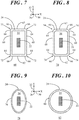
- FIG. 9 shows top view of magnetic sense element 22 and shield structure 24 demonstrating a geometric configuration of shield structure 24 in accordance with another embodiment.
- shield structure 24 has a continuous structure sidewall 76 that yields an elongated elliptical configuration 78 for shield structure 24, in which elongated elliptical configuration 78 surrounds central region 54 in which magnetic sense element 22 is located.
- FIG. 10 shows top view of magnetic sense element 22 and shield structure 24 demonstrating a geometric configuration of shield structure 24 in accordance with another embodiment.
- shield structure 24 has a continuous structure sidewall 80 that yields a circular elliptical configuration 82 for shield structure 24, in which circular elliptical configuration 82 surrounds central region 54 in which magnetic sense element 22 is located.
- FIGs. 7-10 are for illustrative purposes.
- Alternative shield structures may have differing shapes that have continuous extending structure walls that fully encircle magnetic sense elements 22 for effectively shunting stray magnetic fields 42, 44.
- FIGs. 11-17 the ensuing discussion will be directed to various geometric configurations for magnetic field deflection elements 38.
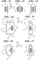
- FIG. 11 shows a simplified top view of a configuration of magnetic sense element 22 with magnetic field deflection element 38.
- FIG. 12 shows a simplified top view of another configuration of magnetic sense elements 22 with magnetic field deflection element 38.
- FIG. 13 shows a simplified top view of another configuration of magnetic sense element 22 with magnetic field deflection elements 38.
- Each of the configurations shown in FIGs. 11-13 include a dedicated soft magnetic structure for redirecting out-of-plane magnetic field 34 ( FIG. 2 ) into in-plane measurement magnetic field 40 ( FIG. 1 ).
- a single magnetic field deflection element 38 is located proximate a single magnetic sense element 22 and is therefore designated as a one-sided simple bar.
- a single magnetic field deflection element 38 is located between a pair of magnetic sense elements 22 and is therefore designated as a doubled-sided simple bar.
- a single magnetic sense element 22 is located between a pair of magnetic deflection elements 38, each of which is configured as a simple bar. It should be understood that various alternative configurations of magnetic field deflection element 38 may suitably redirect out-of-plane magnetic field 34 into in-plane measurement magnetic field 40.
- FIG. 14 shows a simplified top view of a configuration of magnetic sense element 22 with shield structure 24.
- FIG 15 shows a simplified top view of another configuration of magnetic sense element 22 with shield structure 24.
- FIG 16 shows a simplified top view of another configuration of magnetic sense element 22 with shield structure 24.
- FIG. 17 shows a simplified top view of another configuration of magnetic sense element 22 with shield structure 24.
- shield structure 24 serves a dual purpose of both suppressing stray magnetic fields 42, 44 and redirecting out-of-plane magnetic field 34 ( FIG. 2 ) to produce in-plane measurement magnetic field 40 ( FIG. 1 ).
- magnetic sense element 22 is located in central region 54 encircled by a rectangular configuration of shield structure 24 at a position that is offset from a center point 84 of central region 54.
- shield structure 24 fully encircles magnetic sense element 22 to suppress stray magnetic fields 42, 44.
- sidewall 60 of shield structure 24 also serves to redirect out-of-plane magnetic field 34 ( FIG. 2 ) into in-plane measurement magnetic field 40 ( FIG. 1 ) in a one-sided configuration.
- magnetic sense element 22 is located in central region 54 encircled by a rectangular configuration of shield structure 24 at a generally centered position of central region 54.
- shield structure 24 fully encircles magnetic sense element 22 to suppress stray magnetic fields 42, 44.
- the rectangular shape of shield structure 24 is significantly narrowed so that magnetic sense element 22 is very close to two sidewalls 60 of shield structure 24. Due to the proximity of magnetic sense element 22 to two sidewalls 60, shield structure 24 also serves to redirect out-of-plane magnetic field 34 ( FIG. 2 ) into in-plane measurement magnetic field 40 ( FIG. 1 ) in a double-sided configuration.
- magnetic sense element 22 is located in central region 54 encircled by an elongated elliptical configuration of shield structure 24 at a position that is offset from center point 84 of central region 54.
- shield structure 24 fully encircles magnetic sense element 22 to suppress stray magnetic fields 42, 44.
- shield structure 24 also serves to redirect out-of-plane magnetic field 34 ( FIG. 2 ) into in-plane measurement magnetic field 40 ( FIG. 1 ) in a one-sided configuration.
- magnetic sense element 22 is located in central region 54 encircled by an elongated elliptical configuration of shield structure 24 at a generally centered position of central region 54.
- shield structure 24 fully encircles magnetic sense element 22 to suppress stray magnetic fields 42, 44.
- the elliptical shape of shield structure 24 is significantly narrowed so that two sides of magnetic sense element 22 is very close to continuous structure sidewall 76 of shield structure 24. Due to the proximity of two sides of magnetic sense element 22 to continuous structure sidewall 76, shield structure 24 also serves to redirect out-of-plane magnetic field 34 ( FIG. 2 ) into in-plane measurement magnetic field 40 ( FIG. 1 ) in a double-sided configuration.
- shield structure 24 may suitably serve a dual function of both suppressing stray magnetic fields 42, 44 and redirecting out-of-plane magnetic field 34 to produce in-plane measurement magnetic field 40.
- FIG. 18 shows a simplified partial side view a system 90 for rotation angle sensing and FIG. 19 shows a simplified top view of system 90.
- magnetic sense elements 22 with integrated shield structures 24 may be suitably configured to sense angular position of an object in a gradiometer configuration.
- System 90 generally includes first and second gradient units 92, 94 formed on a surface 96 of a substrate 98 and a magnet 100 vertically displaced away from first and second gradient units 92, 94 along Z-axis 36. Magnet 100 is not shown in the top view illustrated in FIG. 19 in order to better visualize the features formed on surface 96 of substrate 98.
- First gradient unit 92 includes a first one of magnetic sense elements (labeled 22A) and one of magnetic field deflection elements (labeled 38 1 ) fully encircled by a first shield structure (labeled 24i) and a second one of the magnetic sense elements (labeled 22A') and one of magnetic field deflection elements (labeled 38 2 ) fully encircled by a second shield structure (labeled 24 2 ).
- second gradient unit 94 includes a third one of magnetic sense elements (labeled 22B) and one of magnetic field deflection elements (labeled 38 3 ) fully encircled by a third shield structure (labeled 24 3 ) and a fourth one of the magnetic sense elements (labeled 22B') and one of magnetic field deflection elements (labeled 38 4 ) fully encircled by a fourth shield structure (labeled 24 4 ).
- second gradient unit 94 is rotated ninety degrees relative to first gradient unit 92. That is, a longitudinal dimension of first and second magnetic sense elements, 22A, 22A' and is aligned with X-axis 30. Additionally, a longitudinal dimension of third and fourth magnetic sense elements, 22B, 22B' is aligned with Y-axis 32.
- magnetic sense elements 22A, 22A' are configured to sense an in-plane measurement magnetic field 102 along a first sense axis, i.e., Y-axis 32, oriented approximately parallel to surface 96 of substrate 98.
- Magnetic sense elements 22B, 22B' are configured to sense an in-plane measurement magnetic field 104 along a second sense axis, i.e., X-axis 30, oriented approximately parallel to surface 96 of substrate 98. Any difference in the magnetic field strength measured by each of magnetic sense elements, 22B, 22B' can be used to determine the magnetic field gradient in a direction parallel to X-axis 30.
- Second gradient unit 94 is spaced apart from first gradient unit 92 by ninety degrees relative to an axis of rotation 106 perpendicular surface 96 of substrate 98. Additionally, first and second gradient units 92, 94 are located the same radial distance 108 away from axis of rotation 106. Further, first magnetic sense element 22A is laterally spaced apart from second magnetic sense element 22A' by a distance 110 and third magnetic sense element 22B is laterally spaced apart from fourth magnetic sense element 22B' by the same distance 110. In another embodiment, the distance between magnetic sense elements 22A, 22A', 22B, and 22B' may differ.
- Magnet 100 may be a permanent magnet in the form of, for example, a disc, ring, rectangle, or bar shape. Magnet 100 is configured to rotate about axis of rotation 106 relative to first and second gradient units 92, 94. Magnet 100 produces a magnetic field 112 that rotates along with magnet 100 relative to first and second gradient units 92, 94. Magnetic field 112 has an out-of-plane magnetic field component 114 having a magnetic field strength that changes as a function of the distance from axis of rotation 106, as represented by varying length arrows. By way of example, the magnetic field strength may be lowest at locations nearest to axis of rotation 106 and greatest at locations farthest from axis of rotation 106.
- out-of-plane magnetic field component 114 is detectable by first and second gradient units 92, 94, and thus may be referred to herein as a magnetic gradient field 114.
- magnetic field deflection elements 38 1 , 38 2 , 38 3 , 38 4 may suitably redirect the out-of-plane magnetic field component 114 into the X-Y plane defined by X-axis 30 and Y-axis 32 for detection by magnetic sense elements 22A, 22A', 22B, 22B'.
- magnetic sense elements 22A, 22A', 22B, 22B' may be configured to directly sense an out-of-plane magnetic field.
- gradient units 92 and 94 need not include magnetic field deflection elements 38 1 , 38 2 , 38 3 , 38 4 .
- out-of-plane magnetic field component 114 detected by first and second gradient units 92, 94 may be suitably processed to identify a rotation angle, 116, labeled ⁇ , of magnet 100 relative to first and second gradient units 92, 94.
- first and second gradient units 92, 94 may include a multitude of gradient units. In such a configuration, the signals of the opposing gradient unit may be averaged or the like. Thus, possible errors from eccentricity and so forth may be mitigated.
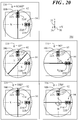
- FIG. 20 shows a table 118 of possible rotation angles 116, ⁇ , of magnet 100 rotating relative to magnetic sense elements 22A, 22A', 22B, 22B' of first and second gradient units 92, 94 of system 90 ( FIG. 18 ).
- magnet 100 is a diametrically magnetized magnet that is magnetized across its diameter, having the north and south poles located at opposing sides of magnet 100 relative to its diameter.
- Rotation angles 116 shown in FIG. 20 are provided as examples only. It should be understood that can be many more possible rotation angles 116 ranging between 0 and 360°.
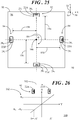
- FIG. 21 shows a block diagram of system 90.
- First gradient unit 92 including first and second magnetic sense elements 22A, 22A' fully encircled by shield structures (not shown, described above) have inputs coupled to a processing circuit 120.
- second gradient unit 94 including third and fourth magnetic sense elements 22B, 22B' fully encircled by shield structures (not shown, described above) have inputs coupled to processing circuit 120.
- First magnetic sense element 22A is configured to produce a first output signal 122, V A , in response to out-of-plane magnetic field component 114 of magnetic field 112 ( FIG. 18 ).
- Second magnetic sense element 22A' is configured to produce a second output signal 124, V A' , in response to out-of-plane magnetic field component 114 ( FIG.
- Third magnetic sense element 22B is configured to produce a third output signal 126, V B , in response to out-of-plane magnetic field component 114 of magnetic field 112.
- fourth magnetic sense element 22B' is configured to produce a fourth output signal 128, V B' , in response to out-of-plane magnetic field component 114 of magnetic field 112.
- FIG. 22 shows a graph 130 of an example a magnetic gradient field distribution in a direction parallel to Y-axis 32 ( FIG. 19 ) produced by magnet 100 ( FIG. 18 ). That is, graph 130 demonstrates the change in the deflected in-plane measurement magnetic field 102 parallel to Y-axis 32 in response to the out-of-plane magnetic field component 114 ( FIG. 18 ) produced by magnet 100 ( FIG. 18 ).
- This example is provided for the case in which rotation angle 116, ⁇ , is equal to 90°, as presented above in connection with FIG. 20 .
- the magnetic gradient field distribution is shown with and without the presence of a magnetic interference field component 132, B i .
- FIG. 23 shows a graph 134 of an example of a magnetic gradient field distribution in a direction parallel to X-axis 30 ( FIG. 19 ) produced by magnet 100. That is, graph 134 demonstrates the change in the deflected in-plane measurement field 104 parallel to X-axis 130 in response to the out-of-plane magnetic field component 114 produced by magnet 100.
- This example is provided for the case in which rotation angle 116, ⁇ , is equal to 90°, as presented above in connection with FIG. 20 .
- the magnetic gradient field distribution is shown with and without the presence of a magnetic interference field component 136, B i .
- FIG. 22 thus shows graph 130 of the magnetic field strength resulting in first and second output voltage signals 122, 124 for first gradient unit 92 and an effect that magnetic interference field component 132, B i , may have on first and second output voltage signals 122, 124.
- FIG. 22 thus shows graph 134 of the magnetic field strength resulting third and fourth output voltage signals 126, 128 for second gradient unit 94 and an effect that magnetic interference field component 136, B i , may have on third and fourth output voltage signals 126, 128.
- a dotted line 138 represents a linear gradient range and related magnetic field/magnetic flux, B, 131 (resulting in first and second output voltage signals 122,124) at the relative positions defined by radial distance 108 ( FIG. 19 ) from axis of rotation 106 ( FIG. 19 ) and distance 110 ( FIG. 19 ) between first and second magnetic sense elements 22A, 22A'.
- a solid line 140 represents a linear gradient range and related magnetic field/magnetic flux 131 (resulting in first and second output voltage signals 122, 124) with an additional spatial homogenous interference magnetic field component 132, B i .
- a dotted line 142 represents a linear gradient range and related magnetic field/magnetic flux 131 (resulting in third and fourth output voltage signals 126, 128) at the relative positions defined by radial distance 108 from axis of rotation 106 and distance 110 between third and fourth magnetic sense elements 22B, 22B'.
- a solid line144 represents a linear gradient range and related magnetic field/magnetic flux 131 (resulting in third and fourth output voltage signals 126, 128) with an additional spatial homogenous magnetic interference field component 136, Bi.
- Processing circuit 120 may be an application specific integrated circuit (ASIC) that includes a combination of hardware and software for suitably processing first, second, third, and fourth output voltage signals 122, 124, 126, 128 to identify rotation angle 116.
- Processing circuit 120 is electrically coupled with first gradient unit 92 and is configured to produce a first differential output signal 146 as a difference between first and second output voltage signals 122, 124, the difference between first and second output voltage signals 122, 124 cancelling magnetic interference field component 132.
- processing circuit 120 is electrically coupled with second gradient unit 94 and is configured to produce a second differential output signal 148 as a difference between third and fourth output voltage signals 126, 128, the difference between the third and fourth output voltage signals 126, 128 cancelling magnetic interference field component 136.
- Shield structure 24 ( FIG. 1 ) suppresses stray magnetic fields 42, 44 ( FIG. 1 ), thus largely eliminating their effect on the sensitivity of the magnetic sense elements 22A, 22A', 22B, 22B'.
- Rotation angle 116 of magnet 100 ( FIG. 18 ) relative to first and second gradient units 92, 94 can thereafter be identified by division of the first and second differential output signals.
- S is the sensitivity of the magnetic sense elements and is assumed to be equal for both of first and second magnetic sense elements 22A, 22A' (e.g., achieved by fabrication accuracy or trimming).
- V A ′ S ⁇ B A ′ + S + B i
- FIG. 24 shows a graph 150 of a change of a magnetic field 152 at the positions of first and second gradient units 92, 94 ( FIG. 19 ) as functions of rotation angle 116.
- a solid curve 153 represents a change of magnetic field component 152 at sensing element 22A and a dotted curve 154 represents a change of magnetic field component 152 at sensing element 22B as a functions of rotation angle 116.
- B mGA (B m ' -B m ).
- FIG. 25 shows a simplified top view of magnetic sense elements 22A, 22A', 22B, 22B' of first and second gradient units 92, 94 in a symmetric position relative to axis of rotation 106.
- first gradient unit 92 includes a first one of magnetic sense elements (labeled 22A) and one of magnetic field deflection elements (labeled 38 1 ) fully encircled by a first shield structure (labeled 24 1 ) and a second one of the magnetic sense elements (labeled 22A') and one of magnetic field deflection elements (labeled 38 2 ) fully encircled by a second shield structure (labeled 24 2 ).
- second gradient unit 94 includes a third one of magnetic sense elements (labeled 22B) and one of magnetic field deflection elements (labeled 38 3 ) fully encircled by a third shield structure (labeled 24 3 ) and a fourth one of the magnetic sense elements (labeled 22B') and one of magnetic field deflection elements (labeled 38 4 ) fully encircled by a fourth shield structure (labeled 24 4 ).
- magnetic sense elements 22A, 22A' of first gradient unit 92 are disposed in the Y-direction on opposing sides of X-axis 30. Further, magnetic sense elements 22A, 22A' are displaced away from X-axis 30 by the same distance 156.
- magnetic sense elements 22B, 22B' of second gradient unit 94 are disposed in the X-direction on opposing sides of Y-axis 32. Further, magnetic sense elements 22B, 22B' are displaced away from Y-axis 32 by the same distance 158. In other embodiments, distances 156, 158 need not be the same. Equations (1) through (20) described above may be implemented in connection with the configuration of FIG. 25 to determine rotation angle 116.
- a larger the distance between the magnetic sense elements of a gradient unit can yield a larger magnetic field gradient (i.e., the difference between the magnetic field strength measured at each of the two magnetic sense elements).
- This larger magnetic field gradient can enable greater tolerance of the width of an air gap between magnet 100 ( FIG. 18 ) and first and second gradient units 92, 94.
- a larger maximum permissible air gap may enable a relaxation of restrictions on the mechanical tolerances of the angular position sensor without incurring potential signal loss, e.g., signal dropouts, during operation.
- FIG. 26 shows a graph 160 of an example magnetic gradient field distribution along the sensing axis (e.g., Y-axis 32) for first gradient unit 92 of the configuration of FIG. 25 . That is, graph 160 demonstrates the change in magnetic field strength 162 of the redirected/deflected in-plane measurement magnetic field 102 parallel to Y-axis 32 in response to the out-of-plane magnetic gradient field 114 ( FIG. 18 ) produced by magnet 100 ( FIG. 18 ).
- This example is provided for the case in which rotation angle 116, ⁇ , is equal to 90°, as presented above in connection with FIG. 20 .
- the magnitude of magnetic field, B A sensed at magnetic sense element 22A will be equivalent to, but opposite in sign from, the magnetic field, -B A' , sensed at magnetic sense element 22A'.
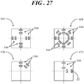
- FIG. 27 shows various simplified top views showing positions of gradient units that may alternatively be incorporated into the system of FIG 18 .
- alternative embodiments of system 90 may include a multitude of gradient units. Further, these gradient units may be arranged differently. Accordingly, FIG. 27 includes a first configuration 164 having four gradient units 166 each separated by 90°. Additionally, a second configuration 168 is shown having eight gradient units 166, each separated by 45°. A third configuration 170 is shown having two gradient units 166, separated by 45°. And a fourth configuration 172 is shown having two gradient units 166, in which the magnetic sense elements 22 are separated by a greater distance than that shown previously. FIG. 27 only shows a few configurations of gradient units. Other configurations may be equivalently applicable.
- Embodiments described herein entail magnetic field sensors and magnetic field sensor systems with integrated magnetic field shield structures for measuring magnetic fields while suppressing stray magnetic fields.
- An embodiment of magnetic field sensor comprises a magnetic sense element formed on a substrate and a shield structure formed on the substrate and fully encircling the magnetic sense element, the shield structure being configured to suppress stray magnetic fields along a first axis and a second axis, wherein the first and second axes are parallel to a surface of the substrate and perpendicular to one another.
- the shield structure encircles the magnetic sense element along the first and second axes parallel to the surface of the substrate.
- the shield structure does not encircle the magnetic sense element in a direction perpendicular to the surface of the substrate.
- the magnetic sense element is configured to sense an external magnetic field along a third axis oriented perpendicular to a surface of the substrate.
- an external magnetic field is oriented along a third axis perpendicular to a surface of the substrate, the magnetic sense element is configured to sense a measurement magnetic field along the first axis.
- the magnetic field sensor further comprises a magnetic field deflection element formed on the substrate proximate the magnetic sense element. The magnetic field deflection element is configured to redirect the external magnetic field from the third axis into the first axis to be sensed as the measurement magnetic field by the magnetic sense element.
- the shield structure additionally encircles sidewalls of the magnetic field deflection element.
- the shield structure comprises first structure sidewalls facing one another and second structure sidewalls facing one another. First ends of the first structure sidewalls are coupled to second ends of the second structure sidewalls to yield a rectangular configuration for the shield structure.
- the rectangular configuration has a central region, and the magnetic sense element is located in the central region.
- each intersection of one of the first ends with one of the second ends exhibits a curved shape.
- the shield structure comprises a continuous structure sidewall to yield an elliptical configuration for the shield structure.
- the elliptical configuration has a central region, and the magnetic sense element is located in the central region.
- the shield structure encircles a central region, and the magnetic sense element is located in the central region at a position that is offset from a center point of the central region.
- the magnetic sense element is a first magnetic sense element and the shield structure is a first shield structure.
- the magnetic field sensor further comprises a second magnetic sense element formed on the substrate; and a second shield structure formed on the substrate and fully encircling sidewalls of the second magnetic sense element.
- the second shield structure is configured to suppress the stray magnetic fields along the first axis and the second axis.
- the first and second magnetic sense elements are spaced apart from one another to form a gradient unit configured to determine a magnetic field gradient.
- the gradient unit is implemented in an angular position sensor.
- the substrate is an active silicon substrate.
- a magnetic field sensor comprises a magnetic sense element formed on an active silicon substrate, a shield structure formed on the active silicon substrate and fully encircling the magnetic sense element, the shield structure being configured to suppress stray magnetic fields along a first axis and a second axis, and a magnetic field deflection element formed on the substrate proximate the magnetic sense element and fully encircled by the shield structure.
- the first and second axes are parallel to a surface of the substrate and perpendicular to one another, a magnetic field is oriented along a third axis perpendicular to a surface of the active silicon substrate, the magnetic sense element is configured to sense a measurement magnetic field along the first axis, and the magnetic field deflection element is configured to redirect the magnetic field from the third axis into the first axis to be sensed as the measurement magnetic field by the magnetic sense element.
- the shield structure comprises first structure sidewalls facing one another and second structure sidewalls facing one another. First ends of the first structure sidewalls are coupled to second ends of the second structure sidewalls to yield a rectangular configuration for the shield structure.
- the rectangular configuration has a central region.
- the magnetic sense element and the magnetic field deflection element are located in the central region.
- the shield structure comprises a continuous structure sidewall to yield an elliptical configuration for the shield structure.
- the elliptical configuration has a central region.
- the magnetic sense element and the magnetic field deflection element are located in the central region.
- the shield structure encircles a central region.
- the magnetic sense element and the magnetic field deflection element are located in the central region.
- the magnetic sense element is located at a position that is offset from a center point of the central region.
- An embodiment of a magnetic field sensor system comprises a gradient unit formed on a substrate.
- the gradient unit comprises a first magnetic sense element and a first shield structure fully encircling the first magnetic sense element, the first shield structure being configured to suppress stray magnetic fields along a first axis and a second axis, wherein the first and second axes are parallel to a surface of the substrate and perpendicular to one another.
- the gradient unit further comprises a second magnetic sense element formed on the substrate and a second shield structure formed on the substrate and fully encircling the second magnetic sense element, the second shield structure being configured to suppress the stray magnetic fields along the first axis and the second axis.
- the first and second magnetic sense elements are laterally spaced apart from one another and configured to sense a magnetic field along a third axis oriented perpendicular to a surface of the substrate, wherein the gradient unit is configured to determine a magnetic field gradient in response to the sensed magnetic field at each of the first and second magnetic sense elements.
- the magnetic field sensor system further comprises a magnet configured to rotate about an axis of rotation relative to the gradient unit.
- the magnet produces the magnetic field.
- the gradient unit is implemented in an angular position sensor.
- the magnetic field shield structures may be vertically integrated with the magnetic sense elements to achieve reductions in size and cost savings. Further, the magnetic field sense elements with the shield structures can be implemented in various system configurations for the purpose of rotation angle sensing.
- the shield structures can effectively suppress stray fields along the non-sensing axis or axes and the gradiometer configuration can cancel stray magnetic fields along the sensing axis to positively enhance the magnetic field detection quality.
Landscapes
- Physics & Mathematics (AREA)
- General Physics & Mathematics (AREA)
- Condensed Matter Physics & Semiconductors (AREA)
- Health & Medical Sciences (AREA)
- Engineering & Computer Science (AREA)
- Environmental & Geological Engineering (AREA)
- Toxicology (AREA)
- Measuring Magnetic Variables (AREA)
Applications Claiming Priority (1)
| Application Number | Priority Date | Filing Date | Title |
|---|---|---|---|
| US15/703,102 US10718825B2 (en) | 2017-09-13 | 2017-09-13 | Stray magnetic field robust magnetic field sensor and system |
Publications (2)
| Publication Number | Publication Date |
|---|---|
| EP3457155A1 true EP3457155A1 (de) | 2019-03-20 |
| EP3457155B1 EP3457155B1 (de) | 2023-02-15 |
Family
ID=62873281
Family Applications (1)
| Application Number | Title | Priority Date | Filing Date |
|---|---|---|---|
| EP18181774.3A Active EP3457155B1 (de) | 2017-09-13 | 2018-07-04 | Gegen magnetische streufelder robuster magnetischer feldsensor und system |
Country Status (3)
| Country | Link |
|---|---|
| US (1) | US10718825B2 (de) |
| EP (1) | EP3457155B1 (de) |
| CN (1) | CN109490795B (de) |
Cited By (4)
| Publication number | Priority date | Publication date | Assignee | Title |
|---|---|---|---|---|
| EP3742129A1 (de) * | 2019-05-23 | 2020-11-25 | Melexis Technologies SA | Magnetisches positionssensorsystem, vorrichtung, magnet und verfahren |
| WO2021052727A1 (en) * | 2019-09-18 | 2021-03-25 | Analog Devices International Unlimited Company | Sensor with magnetic shield |
| EP3882646A1 (de) * | 2020-03-18 | 2021-09-22 | TE Connectivity Germany GmbH | Integriertes magnetometer und verfahren zur detektion eines magnetfeldes |
| US11293784B2 (en) | 2020-05-06 | 2022-04-05 | Melexis Technologies Sa | Magnetic position sensor system and method |
Families Citing this family (7)
| Publication number | Priority date | Publication date | Assignee | Title |
|---|---|---|---|---|
| MX395430B (es) * | 2016-06-29 | 2025-03-26 | Tae Tech Inc | Bucle de flujo combinado aislado mineral y alambre de punto b |
| US10670386B2 (en) * | 2018-04-19 | 2020-06-02 | Infineon Technologies Ag | Multi-turn counter sensor failure detection |
| WO2020040168A1 (ja) | 2018-08-22 | 2020-02-27 | 旭化成エレクトロニクス株式会社 | 磁場計測装置、磁場計測方法、磁場計測プログラム |
| JP6936405B2 (ja) | 2018-12-26 | 2021-09-15 | 旭化成エレクトロニクス株式会社 | 磁場計測装置 |
| EP3754356B1 (de) * | 2019-06-21 | 2023-07-26 | Melexis Technologies SA | Streufeldimmune magnetfeldsensoranordnung, magnetdrehmomentsensoranordnung und verfahren zur bestimmung eines magnetischen flusses |
| WO2022192682A2 (en) | 2021-03-11 | 2022-09-15 | Trustees Of Boston University | Single point gradiometer |
| US11754646B2 (en) | 2021-03-24 | 2023-09-12 | Analog Devices International Unlimited Company | Magnetic sensor system |
Citations (4)
| Publication number | Priority date | Publication date | Assignee | Title |
|---|---|---|---|---|
| WO1998054547A1 (en) * | 1997-05-29 | 1998-12-03 | Laboratorium Für Physikalische Elektronik | Magnetic rotation sensor |
| EP2639594A2 (de) * | 2012-03-14 | 2013-09-18 | Alps Electric Co., Ltd. | Magnetischer Sensor |
| US20150137796A1 (en) * | 2013-11-19 | 2015-05-21 | Infineon Technologies Ag | On-axis magnetic field angle sensors, systems and methods |
| JP2015141121A (ja) * | 2014-01-29 | 2015-08-03 | 株式会社デンソー | 磁気センサ |
Family Cites Families (38)
| Publication number | Priority date | Publication date | Assignee | Title |
|---|---|---|---|---|
| DE59609089D1 (de) | 1995-10-30 | 2002-05-23 | Sentron Ag Zug | Magnetfeldsensor und Strom- oder Energiesensor |
| US5729137A (en) | 1996-10-22 | 1998-03-17 | Nonvolatile Electronics, Incorporated | Magnetic field sensors individualized field reducers |
| US6064197A (en) | 1997-07-26 | 2000-05-16 | U.S. Philips Corporation | Angle sensor having lateral magnetic field sensor element and axial magnetic field direction measuring element for determining angular position |
| JP4936299B2 (ja) | 2000-08-21 | 2012-05-23 | メレクシス・テクノロジーズ・ナムローゼフェンノートシャップ | 磁場方向検出センサ |
| DE10201875C1 (de) | 2002-01-18 | 2003-05-22 | Austriamicrosystems Ag | Sensorsystem und Verfahren zum Betrieb des Sensorsystems |
| DE10314602B4 (de) | 2003-03-31 | 2007-03-01 | Infineon Technologies Ag | Integrierter differentieller Magnetfeldsensor |
| US7112957B2 (en) | 2004-06-16 | 2006-09-26 | Honeywell International Inc. | GMR sensor with flux concentrators |
| US7705586B2 (en) * | 2004-09-27 | 2010-04-27 | Nxp B.V. | Magnetic sensor for input devices |
| US7505233B2 (en) * | 2004-12-15 | 2009-03-17 | International Business Machines Corporation | Magnetic sensor |
| US7768083B2 (en) * | 2006-01-20 | 2010-08-03 | Allegro Microsystems, Inc. | Arrangements for an integrated sensor |
| US8269319B2 (en) * | 2006-10-13 | 2012-09-18 | Tessera, Inc. | Collective and synergistic MRAM shields |
| JP4837749B2 (ja) | 2006-12-13 | 2011-12-14 | アルプス電気株式会社 | 磁気センサ及びそれを用いた磁気エンコーダ |
| JP5592270B2 (ja) | 2008-01-04 | 2014-09-17 | アレグロ・マイクロシステムズ・エルエルシー | 角度センサのための方法および装置 |
| US7923996B2 (en) * | 2008-02-26 | 2011-04-12 | Allegro Microsystems, Inc. | Magnetic field sensor with automatic sensitivity adjustment |
| WO2009151024A1 (ja) | 2008-06-11 | 2009-12-17 | アルプス電気株式会社 | 磁気センサ及び磁気センサモジュール |
| WO2009151023A1 (ja) | 2008-06-11 | 2009-12-17 | アルプス電気株式会社 | 磁気センサ及び磁気センサモジュール |
| JP2009300150A (ja) | 2008-06-11 | 2009-12-24 | Alps Electric Co Ltd | 磁気センサ及び磁気センサモジュール |
| US7956604B2 (en) | 2008-07-09 | 2011-06-07 | Infineon Technologies, Ag | Integrated sensor and magnetic field concentrator devices |
| DE102008041859A1 (de) | 2008-09-08 | 2010-03-11 | Robert Bosch Gmbh | Magnetfeldsensoranordnung zur Messung von räumlichen Komponenten eines magnetischen Feldes |
| US20120217963A1 (en) * | 2010-03-31 | 2012-08-30 | Omron Corporation | Magnetic core, current sensor provided with the magnetic core, and current measuring method |
| US9170309B2 (en) | 2010-06-08 | 2015-10-27 | Infineon Technologies Ag | Through bias pole for IGMR speed sensing |
| CH703405B1 (de) | 2010-07-05 | 2014-05-15 | Melexis Tessenderlo Nv | Magnetischer Winkelsensor. |
| US9116198B2 (en) | 2012-02-10 | 2015-08-25 | Memsic, Inc. | Planar three-axis magnetometer |
| JP2013172040A (ja) | 2012-02-22 | 2013-09-02 | Alps Electric Co Ltd | 磁気センサとその製造方法 |
| CN104246525B (zh) * | 2012-04-23 | 2017-02-22 | 日立金属株式会社 | 磁传感器设备 |
| TWI490517B (zh) * | 2012-11-12 | 2015-07-01 | Univ Nat Kaohsiung Applied Sci | Magnetic field sensing device with magnetometer and gradient meter |
| CN105074487B (zh) * | 2013-03-08 | 2018-03-16 | 韩国标准科学研究院 | 用于测量磁场的屏蔽装置、屏蔽方法及消磁 |
| WO2015194370A1 (ja) * | 2014-06-20 | 2015-12-23 | 日立オートモティブシステムズ株式会社 | 電流検出装置 |
| JP6430201B2 (ja) * | 2014-09-30 | 2018-11-28 | 株式会社東芝 | センサ |
| TWI531807B (zh) * | 2015-01-08 | 2016-05-01 | 國立臺灣大學 | 含蔽磁體之磁性元件之識別系統及其方法 |
| DE102015101246A1 (de) * | 2015-01-28 | 2016-07-28 | Fraba B.V. | Magnet-basiertes Drehwinkelmesssystem |
| CN104820125B (zh) * | 2015-04-27 | 2018-04-06 | 江苏多维科技有限公司 | 采用z轴磁电阻梯度计和引线框电流的集成电流传感器 |
| JP2017000354A (ja) * | 2015-06-09 | 2017-01-05 | セイコーエプソン株式会社 | 磁場計測装置および磁場計測方法 |
| US9634242B2 (en) | 2015-07-27 | 2017-04-25 | Seagate Technology Llc | Data reader with front shield coupling structure |
| DE102016103325B4 (de) * | 2016-02-25 | 2025-03-20 | Infineon Technologies Ag | Magnetischer Winkelpositionssensor |
| US10746821B2 (en) * | 2016-06-15 | 2020-08-18 | Denso Corporation | Current sensor |
| US20170370883A1 (en) * | 2016-06-23 | 2017-12-28 | Auburn University | Multi-spot contaminant detection with magnetostrictive sensors |
| US10261138B2 (en) * | 2017-07-12 | 2019-04-16 | Nxp B.V. | Magnetic field sensor with magnetic field shield structure and systems incorporating same |
-
2017
- 2017-09-13 US US15/703,102 patent/US10718825B2/en active Active
-
2018
- 2018-07-04 EP EP18181774.3A patent/EP3457155B1/de active Active
- 2018-08-31 CN CN201811018563.8A patent/CN109490795B/zh active Active
Patent Citations (4)
| Publication number | Priority date | Publication date | Assignee | Title |
|---|---|---|---|---|
| WO1998054547A1 (en) * | 1997-05-29 | 1998-12-03 | Laboratorium Für Physikalische Elektronik | Magnetic rotation sensor |
| EP2639594A2 (de) * | 2012-03-14 | 2013-09-18 | Alps Electric Co., Ltd. | Magnetischer Sensor |
| US20150137796A1 (en) * | 2013-11-19 | 2015-05-21 | Infineon Technologies Ag | On-axis magnetic field angle sensors, systems and methods |
| JP2015141121A (ja) * | 2014-01-29 | 2015-08-03 | 株式会社デンソー | 磁気センサ |
Cited By (8)
| Publication number | Priority date | Publication date | Assignee | Title |
|---|---|---|---|---|
| EP3742129A1 (de) * | 2019-05-23 | 2020-11-25 | Melexis Technologies SA | Magnetisches positionssensorsystem, vorrichtung, magnet und verfahren |
| US11326868B2 (en) | 2019-05-23 | 2022-05-10 | Melexis Technologies Sa | Magnetic position sensor system, device, magnet and method |
| US11796305B2 (en) | 2019-05-23 | 2023-10-24 | Melexis Technologies Sa | Magnetic position sensor system, device, magnet and method |
| WO2021052727A1 (en) * | 2019-09-18 | 2021-03-25 | Analog Devices International Unlimited Company | Sensor with magnetic shield |
| US11307055B2 (en) | 2019-09-18 | 2022-04-19 | Analog Devices International Unlimited Company | Sensor with magnetic shield |
| EP3882646A1 (de) * | 2020-03-18 | 2021-09-22 | TE Connectivity Germany GmbH | Integriertes magnetometer und verfahren zur detektion eines magnetfeldes |
| US11614500B2 (en) | 2020-03-18 | 2023-03-28 | Te Connectivity Germany Gmbh | Integrated magnetometer and method of detecting a magnetic field |
| US11293784B2 (en) | 2020-05-06 | 2022-04-05 | Melexis Technologies Sa | Magnetic position sensor system and method |
Also Published As
| Publication number | Publication date |
|---|---|
| CN109490795A (zh) | 2019-03-19 |
| EP3457155B1 (de) | 2023-02-15 |
| US20190079141A1 (en) | 2019-03-14 |
| CN109490795B (zh) | 2023-03-31 |
| US10718825B2 (en) | 2020-07-21 |
Similar Documents
| Publication | Publication Date | Title |
|---|---|---|
| US10718825B2 (en) | Stray magnetic field robust magnetic field sensor and system | |
| EP3447513B1 (de) | Magnetfeldsensor mit magnetfeldabschirmungsstruktur und systeme, die diesen enthalten | |
| CN110133543B (zh) | 利用辅助传感器信号进行杂散场抵消的磁阻传感器系统 | |
| US10914611B2 (en) | Magnetic field sensor system and method for rotation angle measurement | |
| US10670425B2 (en) | System for measuring angular position and method of stray field cancellation | |
| US9103657B2 (en) | Magnetic field sensor system with a biasing magnet producing a spatially symmetric magnetic field within a plane being defined by magnetoresistive sensor elements | |
| US11313700B2 (en) | Magnetic field influence during rotation movement of magnetic target | |
| US10591320B2 (en) | Magnetoresistive sensor with stray field cancellation and systems incorporating same | |
| EP3469314B1 (de) | Magnetfeldsensor zur erfassung einer nähe und/oder eines standorts eines objekts | |
| EP3184954A1 (de) | Magnetoresistiver winkelsensor mit doppelter z-achse | |
| US10816363B2 (en) | Angular sensor system and method of stray field cancellation | |
| CN109655767B (zh) | 一种集成磁结构 | |
| EP3814722A1 (de) | Magnetcodierer | |
| CN115930753A (zh) | 位置传感器系统、光学透镜系统和显示器 | |
| JP5959686B1 (ja) | 磁気検出装置 | |
| KR102941651B1 (ko) | 엔코더용 자기 센서, 평면 홀 자기저항 브릿지 센서 및 엔코더 |
Legal Events
| Date | Code | Title | Description |
|---|---|---|---|
| PUAI | Public reference made under article 153(3) epc to a published international application that has entered the european phase |
Free format text: ORIGINAL CODE: 0009012 |
|
| STAA | Information on the status of an ep patent application or granted ep patent |
Free format text: STATUS: THE APPLICATION HAS BEEN PUBLISHED |
|
| AK | Designated contracting states |
Kind code of ref document: A1 Designated state(s): AL AT BE BG CH CY CZ DE DK EE ES FI FR GB GR HR HU IE IS IT LI LT LU LV MC MK MT NL NO PL PT RO RS SE SI SK SM TR |
|
| AX | Request for extension of the european patent |
Extension state: BA ME |
|
| STAA | Information on the status of an ep patent application or granted ep patent |
Free format text: STATUS: REQUEST FOR EXAMINATION WAS MADE |
|
| 17P | Request for examination filed |
Effective date: 20190920 |
|
| RBV | Designated contracting states (corrected) |
Designated state(s): AL AT BE BG CH CY CZ DE DK EE ES FI FR GB GR HR HU IE IS IT LI LT LU LV MC MK MT NL NO PL PT RO RS SE SI SK SM TR |
|
| STAA | Information on the status of an ep patent application or granted ep patent |
Free format text: STATUS: EXAMINATION IS IN PROGRESS |
|
| 17Q | First examination report despatched |
Effective date: 20200324 |
|
| REG | Reference to a national code |
Ref country code: DE Ref legal event code: R079 Ref document number: 602018046097 Country of ref document: DE Free format text: PREVIOUS MAIN CLASS: G01R0033000000 Ipc: G01D0003080000 |
|
| GRAP | Despatch of communication of intention to grant a patent |
Free format text: ORIGINAL CODE: EPIDOSNIGR1 |
|
| STAA | Information on the status of an ep patent application or granted ep patent |
Free format text: STATUS: GRANT OF PATENT IS INTENDED |
|
| RIC1 | Information provided on ipc code assigned before grant |
Ipc: G01R 33/022 20060101ALI20220922BHEP Ipc: G01R 33/09 20060101ALI20220922BHEP Ipc: G01D 5/14 20060101ALI20220922BHEP Ipc: G01R 33/00 20060101ALI20220922BHEP Ipc: G01D 3/08 20060101AFI20220922BHEP |
|
| INTG | Intention to grant announced |
Effective date: 20221020 |
|
| GRAS | Grant fee paid |
Free format text: ORIGINAL CODE: EPIDOSNIGR3 |
|
| GRAA | (expected) grant |
Free format text: ORIGINAL CODE: 0009210 |
|
| STAA | Information on the status of an ep patent application or granted ep patent |
Free format text: STATUS: THE PATENT HAS BEEN GRANTED |
|
| AK | Designated contracting states |
Kind code of ref document: B1 Designated state(s): AL AT BE BG CH CY CZ DE DK EE ES FI FR GB GR HR HU IE IS IT LI LT LU LV MC MK MT NL NO PL PT RO RS SE SI SK SM TR |
|
| REG | Reference to a national code |
Ref country code: CH Ref legal event code: EP Ref country code: GB Ref legal event code: FG4D |
|
| REG | Reference to a national code |
Ref country code: DE Ref legal event code: R096 Ref document number: 602018046097 Country of ref document: DE |
|
| REG | Reference to a national code |
Ref country code: AT Ref legal event code: REF Ref document number: 1548445 Country of ref document: AT Kind code of ref document: T Effective date: 20230315 Ref country code: IE Ref legal event code: FG4D |
|
| REG | Reference to a national code |
Ref country code: LT Ref legal event code: MG9D |
|
| REG | Reference to a national code |
Ref country code: NL Ref legal event code: MP Effective date: 20230215 |
|
| REG | Reference to a national code |
Ref country code: AT Ref legal event code: MK05 Ref document number: 1548445 Country of ref document: AT Kind code of ref document: T Effective date: 20230215 |
|
| PG25 | Lapsed in a contracting state [announced via postgrant information from national office to epo] |
Ref country code: RS Free format text: LAPSE BECAUSE OF FAILURE TO SUBMIT A TRANSLATION OF THE DESCRIPTION OR TO PAY THE FEE WITHIN THE PRESCRIBED TIME-LIMIT Effective date: 20230215 Ref country code: PT Free format text: LAPSE BECAUSE OF FAILURE TO SUBMIT A TRANSLATION OF THE DESCRIPTION OR TO PAY THE FEE WITHIN THE PRESCRIBED TIME-LIMIT Effective date: 20230615 Ref country code: NO Free format text: LAPSE BECAUSE OF FAILURE TO SUBMIT A TRANSLATION OF THE DESCRIPTION OR TO PAY THE FEE WITHIN THE PRESCRIBED TIME-LIMIT Effective date: 20230515 Ref country code: NL Free format text: LAPSE BECAUSE OF FAILURE TO SUBMIT A TRANSLATION OF THE DESCRIPTION OR TO PAY THE FEE WITHIN THE PRESCRIBED TIME-LIMIT Effective date: 20230215 Ref country code: LV Free format text: LAPSE BECAUSE OF FAILURE TO SUBMIT A TRANSLATION OF THE DESCRIPTION OR TO PAY THE FEE WITHIN THE PRESCRIBED TIME-LIMIT Effective date: 20230215 Ref country code: LT Free format text: LAPSE BECAUSE OF FAILURE TO SUBMIT A TRANSLATION OF THE DESCRIPTION OR TO PAY THE FEE WITHIN THE PRESCRIBED TIME-LIMIT Effective date: 20230215 Ref country code: HR Free format text: LAPSE BECAUSE OF FAILURE TO SUBMIT A TRANSLATION OF THE DESCRIPTION OR TO PAY THE FEE WITHIN THE PRESCRIBED TIME-LIMIT Effective date: 20230215 Ref country code: ES Free format text: LAPSE BECAUSE OF FAILURE TO SUBMIT A TRANSLATION OF THE DESCRIPTION OR TO PAY THE FEE WITHIN THE PRESCRIBED TIME-LIMIT Effective date: 20230215 Ref country code: AT Free format text: LAPSE BECAUSE OF FAILURE TO SUBMIT A TRANSLATION OF THE DESCRIPTION OR TO PAY THE FEE WITHIN THE PRESCRIBED TIME-LIMIT Effective date: 20230215 |
|
| P01 | Opt-out of the competence of the unified patent court (upc) registered |
Effective date: 20230725 |
|
| PG25 | Lapsed in a contracting state [announced via postgrant information from national office to epo] |
Ref country code: SE Free format text: LAPSE BECAUSE OF FAILURE TO SUBMIT A TRANSLATION OF THE DESCRIPTION OR TO PAY THE FEE WITHIN THE PRESCRIBED TIME-LIMIT Effective date: 20230215 Ref country code: PL Free format text: LAPSE BECAUSE OF FAILURE TO SUBMIT A TRANSLATION OF THE DESCRIPTION OR TO PAY THE FEE WITHIN THE PRESCRIBED TIME-LIMIT Effective date: 20230215 Ref country code: IS Free format text: LAPSE BECAUSE OF FAILURE TO SUBMIT A TRANSLATION OF THE DESCRIPTION OR TO PAY THE FEE WITHIN THE PRESCRIBED TIME-LIMIT Effective date: 20230615 Ref country code: GR Free format text: LAPSE BECAUSE OF FAILURE TO SUBMIT A TRANSLATION OF THE DESCRIPTION OR TO PAY THE FEE WITHIN THE PRESCRIBED TIME-LIMIT Effective date: 20230516 Ref country code: FI Free format text: LAPSE BECAUSE OF FAILURE TO SUBMIT A TRANSLATION OF THE DESCRIPTION OR TO PAY THE FEE WITHIN THE PRESCRIBED TIME-LIMIT Effective date: 20230215 |
|
| PG25 | Lapsed in a contracting state [announced via postgrant information from national office to epo] |
Ref country code: SM Free format text: LAPSE BECAUSE OF FAILURE TO SUBMIT A TRANSLATION OF THE DESCRIPTION OR TO PAY THE FEE WITHIN THE PRESCRIBED TIME-LIMIT Effective date: 20230215 Ref country code: RO Free format text: LAPSE BECAUSE OF FAILURE TO SUBMIT A TRANSLATION OF THE DESCRIPTION OR TO PAY THE FEE WITHIN THE PRESCRIBED TIME-LIMIT Effective date: 20230215 Ref country code: EE Free format text: LAPSE BECAUSE OF FAILURE TO SUBMIT A TRANSLATION OF THE DESCRIPTION OR TO PAY THE FEE WITHIN THE PRESCRIBED TIME-LIMIT Effective date: 20230215 Ref country code: DK Free format text: LAPSE BECAUSE OF FAILURE TO SUBMIT A TRANSLATION OF THE DESCRIPTION OR TO PAY THE FEE WITHIN THE PRESCRIBED TIME-LIMIT Effective date: 20230215 Ref country code: CZ Free format text: LAPSE BECAUSE OF FAILURE TO SUBMIT A TRANSLATION OF THE DESCRIPTION OR TO PAY THE FEE WITHIN THE PRESCRIBED TIME-LIMIT Effective date: 20230215 |
|
| REG | Reference to a national code |
Ref country code: DE Ref legal event code: R097 Ref document number: 602018046097 Country of ref document: DE |
|
| PG25 | Lapsed in a contracting state [announced via postgrant information from national office to epo] |
Ref country code: SK Free format text: LAPSE BECAUSE OF FAILURE TO SUBMIT A TRANSLATION OF THE DESCRIPTION OR TO PAY THE FEE WITHIN THE PRESCRIBED TIME-LIMIT Effective date: 20230215 |
|
| PLBE | No opposition filed within time limit |
Free format text: ORIGINAL CODE: 0009261 |
|
| STAA | Information on the status of an ep patent application or granted ep patent |
Free format text: STATUS: NO OPPOSITION FILED WITHIN TIME LIMIT |
|
| 26N | No opposition filed |
Effective date: 20231116 |
|
| PG25 | Lapsed in a contracting state [announced via postgrant information from national office to epo] |
Ref country code: SI Free format text: LAPSE BECAUSE OF FAILURE TO SUBMIT A TRANSLATION OF THE DESCRIPTION OR TO PAY THE FEE WITHIN THE PRESCRIBED TIME-LIMIT Effective date: 20230215 |
|
| PG25 | Lapsed in a contracting state [announced via postgrant information from national office to epo] |
Ref country code: MC Free format text: LAPSE BECAUSE OF FAILURE TO SUBMIT A TRANSLATION OF THE DESCRIPTION OR TO PAY THE FEE WITHIN THE PRESCRIBED TIME-LIMIT Effective date: 20230215 |
|
| PG25 | Lapsed in a contracting state [announced via postgrant information from national office to epo] |
Ref country code: MC Free format text: LAPSE BECAUSE OF FAILURE TO SUBMIT A TRANSLATION OF THE DESCRIPTION OR TO PAY THE FEE WITHIN THE PRESCRIBED TIME-LIMIT Effective date: 20230215 |
|
| REG | Reference to a national code |
Ref country code: CH Ref legal event code: PL |
|
| REG | Reference to a national code |
Ref country code: BE Ref legal event code: MM Effective date: 20230731 |
|
| PG25 | Lapsed in a contracting state [announced via postgrant information from national office to epo] |
Ref country code: LU Free format text: LAPSE BECAUSE OF NON-PAYMENT OF DUE FEES Effective date: 20230704 |
|
| PG25 | Lapsed in a contracting state [announced via postgrant information from national office to epo] |
Ref country code: LU Free format text: LAPSE BECAUSE OF NON-PAYMENT OF DUE FEES Effective date: 20230704 |
|
| REG | Reference to a national code |
Ref country code: IE Ref legal event code: MM4A |
|
| PG25 | Lapsed in a contracting state [announced via postgrant information from national office to epo] |
Ref country code: CH Free format text: LAPSE BECAUSE OF NON-PAYMENT OF DUE FEES Effective date: 20230731 |
|
| PG25 | Lapsed in a contracting state [announced via postgrant information from national office to epo] |
Ref country code: IT Free format text: LAPSE BECAUSE OF FAILURE TO SUBMIT A TRANSLATION OF THE DESCRIPTION OR TO PAY THE FEE WITHIN THE PRESCRIBED TIME-LIMIT Effective date: 20230215 Ref country code: FR Free format text: LAPSE BECAUSE OF NON-PAYMENT OF DUE FEES Effective date: 20230731 Ref country code: BE Free format text: LAPSE BECAUSE OF NON-PAYMENT OF DUE FEES Effective date: 20230731 |
|
| PG25 | Lapsed in a contracting state [announced via postgrant information from national office to epo] |
Ref country code: IE Free format text: LAPSE BECAUSE OF NON-PAYMENT OF DUE FEES Effective date: 20230704 |
|
| PG25 | Lapsed in a contracting state [announced via postgrant information from national office to epo] |
Ref country code: IE Free format text: LAPSE BECAUSE OF NON-PAYMENT OF DUE FEES Effective date: 20230704 |
|
| PG25 | Lapsed in a contracting state [announced via postgrant information from national office to epo] |
Ref country code: BG Free format text: LAPSE BECAUSE OF FAILURE TO SUBMIT A TRANSLATION OF THE DESCRIPTION OR TO PAY THE FEE WITHIN THE PRESCRIBED TIME-LIMIT Effective date: 20230215 |
|
| PG25 | Lapsed in a contracting state [announced via postgrant information from national office to epo] |
Ref country code: BG Free format text: LAPSE BECAUSE OF FAILURE TO SUBMIT A TRANSLATION OF THE DESCRIPTION OR TO PAY THE FEE WITHIN THE PRESCRIBED TIME-LIMIT Effective date: 20230215 |
|
| PGFP | Annual fee paid to national office [announced via postgrant information from national office to epo] |
Ref country code: GB Payment date: 20250619 Year of fee payment: 8 |
|
| PG25 | Lapsed in a contracting state [announced via postgrant information from national office to epo] |
Ref country code: CY Free format text: LAPSE BECAUSE OF FAILURE TO SUBMIT A TRANSLATION OF THE DESCRIPTION OR TO PAY THE FEE WITHIN THE PRESCRIBED TIME-LIMIT; INVALID AB INITIO Effective date: 20180704 |
|
| PG25 | Lapsed in a contracting state [announced via postgrant information from national office to epo] |
Ref country code: HU Free format text: LAPSE BECAUSE OF FAILURE TO SUBMIT A TRANSLATION OF THE DESCRIPTION OR TO PAY THE FEE WITHIN THE PRESCRIBED TIME-LIMIT; INVALID AB INITIO Effective date: 20180704 |
|
| PGFP | Annual fee paid to national office [announced via postgrant information from national office to epo] |
Ref country code: DE Payment date: 20250620 Year of fee payment: 8 |
|
| PG25 | Lapsed in a contracting state [announced via postgrant information from national office to epo] |
Ref country code: TR Free format text: LAPSE BECAUSE OF FAILURE TO SUBMIT A TRANSLATION OF THE DESCRIPTION OR TO PAY THE FEE WITHIN THE PRESCRIBED TIME-LIMIT Effective date: 20230215 |