EP3457159B1 - Procédé de prise d'empreintes par résonance magnétique amélioré - Google Patents
Procédé de prise d'empreintes par résonance magnétique amélioré Download PDFInfo
- Publication number
- EP3457159B1 EP3457159B1 EP17191849.3A EP17191849A EP3457159B1 EP 3457159 B1 EP3457159 B1 EP 3457159B1 EP 17191849 A EP17191849 A EP 17191849A EP 3457159 B1 EP3457159 B1 EP 3457159B1
- Authority
- EP
- European Patent Office
- Prior art keywords
- space
- starting
- space trajectory
- measurement
- skrt
- Prior art date
- Legal status (The legal status is an assumption and is not a legal conclusion. Google has not performed a legal analysis and makes no representation as to the accuracy of the status listed.)
- Active
Links
Images


Classifications
-
- G—PHYSICS
- G01—MEASURING; TESTING
- G01R—MEASURING ELECTRIC VARIABLES; MEASURING MAGNETIC VARIABLES
- G01R33/00—Arrangements or instruments for measuring magnetic variables
- G01R33/20—Arrangements or instruments for measuring magnetic variables involving magnetic resonance
- G01R33/44—Arrangements or instruments for measuring magnetic variables involving magnetic resonance using nuclear magnetic resonance [NMR]
- G01R33/48—NMR imaging systems
- G01R33/4818—MR characterised by data acquisition along a specific k-space trajectory or by the temporal order of k-space coverage, e.g. centric or segmented coverage of k-space
-
- G—PHYSICS
- G01—MEASURING; TESTING
- G01R—MEASURING ELECTRIC VARIABLES; MEASURING MAGNETIC VARIABLES
- G01R33/00—Arrangements or instruments for measuring magnetic variables
- G01R33/20—Arrangements or instruments for measuring magnetic variables involving magnetic resonance
- G01R33/28—Details of apparatus provided for in groups G01R33/44 - G01R33/64
- G01R33/32—Excitation or detection systems, e.g. using radio frequency signals
- G01R33/36—Electrical details, e.g. matching or coupling of the coil to the receiver
- G01R33/3607—RF waveform generators, e.g. frequency generators, amplitude-, frequency- or phase modulators or shifters, pulse programmers, digital to analog converters for the RF signal, means for filtering or attenuating of the RF signal
-
- G—PHYSICS
- G01—MEASURING; TESTING
- G01R—MEASURING ELECTRIC VARIABLES; MEASURING MAGNETIC VARIABLES
- G01R33/00—Arrangements or instruments for measuring magnetic variables
- G01R33/20—Arrangements or instruments for measuring magnetic variables involving magnetic resonance
- G01R33/28—Details of apparatus provided for in groups G01R33/44 - G01R33/64
- G01R33/38—Systems for generation, homogenisation or stabilisation of the main or gradient magnetic field
- G01R33/385—Systems for generation, homogenisation or stabilisation of the main or gradient magnetic field using gradient magnetic field coils
-
- G—PHYSICS
- G01—MEASURING; TESTING
- G01R—MEASURING ELECTRIC VARIABLES; MEASURING MAGNETIC VARIABLES
- G01R33/00—Arrangements or instruments for measuring magnetic variables
- G01R33/20—Arrangements or instruments for measuring magnetic variables involving magnetic resonance
- G01R33/44—Arrangements or instruments for measuring magnetic variables involving magnetic resonance using nuclear magnetic resonance [NMR]
- G01R33/48—NMR imaging systems
- G01R33/4818—MR characterised by data acquisition along a specific k-space trajectory or by the temporal order of k-space coverage, e.g. centric or segmented coverage of k-space
- G01R33/4824—MR characterised by data acquisition along a specific k-space trajectory or by the temporal order of k-space coverage, e.g. centric or segmented coverage of k-space using a non-Cartesian trajectory
-
- G—PHYSICS
- G01—MEASURING; TESTING
- G01R—MEASURING ELECTRIC VARIABLES; MEASURING MAGNETIC VARIABLES
- G01R33/00—Arrangements or instruments for measuring magnetic variables
- G01R33/20—Arrangements or instruments for measuring magnetic variables involving magnetic resonance
- G01R33/44—Arrangements or instruments for measuring magnetic variables involving magnetic resonance using nuclear magnetic resonance [NMR]
- G01R33/48—NMR imaging systems
- G01R33/54—Signal processing systems, e.g. using pulse sequences ; Generation or control of pulse sequences; Operator console
- G01R33/543—Control of the operation of the MR system, e.g. setting of acquisition parameters prior to or during MR data acquisition, dynamic shimming, use of one or more scout images for scan plane prescription
-
- G—PHYSICS
- G01—MEASURING; TESTING
- G01R—MEASURING ELECTRIC VARIABLES; MEASURING MAGNETIC VARIABLES
- G01R33/00—Arrangements or instruments for measuring magnetic variables
- G01R33/20—Arrangements or instruments for measuring magnetic variables involving magnetic resonance
- G01R33/44—Arrangements or instruments for measuring magnetic variables involving magnetic resonance using nuclear magnetic resonance [NMR]
- G01R33/48—NMR imaging systems
- G01R33/54—Signal processing systems, e.g. using pulse sequences ; Generation or control of pulse sequences; Operator console
- G01R33/56—Image enhancement or correction, e.g. subtraction or averaging techniques, e.g. improvement of signal-to-noise ratio and resolution
- G01R33/5602—Image enhancement or correction, e.g. subtraction or averaging techniques, e.g. improvement of signal-to-noise ratio and resolution by filtering or weighting based on different relaxation times within the sample, e.g. T1 weighting using an inversion pulse
-
- G—PHYSICS
- G01—MEASURING; TESTING
- G01R—MEASURING ELECTRIC VARIABLES; MEASURING MAGNETIC VARIABLES
- G01R33/00—Arrangements or instruments for measuring magnetic variables
- G01R33/20—Arrangements or instruments for measuring magnetic variables involving magnetic resonance
- G01R33/44—Arrangements or instruments for measuring magnetic variables involving magnetic resonance using nuclear magnetic resonance [NMR]
- G01R33/48—NMR imaging systems
- G01R33/4828—Resolving the MR signals of different chemical species, e.g. water-fat imaging
-
- G—PHYSICS
- G01—MEASURING; TESTING
- G01R—MEASURING ELECTRIC VARIABLES; MEASURING MAGNETIC VARIABLES
- G01R33/00—Arrangements or instruments for measuring magnetic variables
- G01R33/20—Arrangements or instruments for measuring magnetic variables involving magnetic resonance
- G01R33/44—Arrangements or instruments for measuring magnetic variables involving magnetic resonance using nuclear magnetic resonance [NMR]
- G01R33/48—NMR imaging systems
- G01R33/50—NMR imaging systems based on the determination of relaxation times, e.g. T1 measurement by IR sequences; T2 measurement by multiple-echo sequences
Definitions
- the invention relates to an improvement of magnetic resonance fingerprinting methods.
- Magnetic resonance technology (hereinafter the abbreviation MR stands for magnetic resonance) is a well-known technology with which images of the interior of an object under investigation can be generated.
- the object under investigation is positioned in a magnetic resonance system in a comparatively strong static, homogeneous basic magnetic field, also known as a B 0 field, with field strengths of 0.2 Tesla to 7 Tesla and more, so that its nuclear spins are oriented along the basic magnetic field.
- RF pulses high-frequency excitation pulses
- MR images are reconstructed or spectroscopy data are determined on this basis.
- the recorded measurement data are digitized and stored as complex numerical values in a k-space matrix. From the k-space matrix filled with values, an associated MR image can be reconstructed, for example by means of a multidimensional Fourier transformation.
- Magnetic resonance imaging using a magnetic resonance system can be used to determine the presence and/or distribution of a substance in an object under examination.
- the substance can be, for example, a possibly pathological tissue of the object under examination, a contrast agent, a marking substance or a metabolic product.
- Information about the substances present can be obtained in a variety of ways from the recorded measurement data.
- a relatively simple source of information is, for example, image data reconstructed from the measurement data.
- there are also more complex methods that determine information about the object being examined for example from pixel-time series of image data reconstructed from successively measured measurement data sets.
- Such methods include, for example, magnetic resonance fingerprinting (MRF) methods, in which signal curves of image data reconstructed from measurement data recorded one after the other using different recording parameters, the "fingerprinting parameters", are compared using pattern recognition methods with signal curves from a previously determined database of signal curves characteristic of certain substances ("dictionary") in order to determine the substances represented in the image data reconstructed from the measurement data or the spatial distribution of tissue-specific parameters (such as the transverse relaxation T2 or the longitudinal relaxation T1; so-called T1 and T2 maps) in the imaged object under examination.
- MRF magnetic resonance fingerprinting
- Magnetic resonance fingerprinting techniques are described, for example, in the article by Ma et al., “Magnetic Resonance Fingerprinting,” Nature, 495: pp. 187-192 (2013 ), the article by Jiang et al., “MR Fingerprinting Using Fast Imaging with Steady State Precession (FISP) with Spiral Readout,” Magnetic Resonance in Medicine 74: pp. 1621-1631 (2015 ) or the article by Cloos et al. "Online Radial Multiband Magnetic Resonance Fingerprinting", ISMRM 2016: p. 608 known.
- FISP Steady State Precession
- an MRF method uses a FISP ("Fast Imaging with Steady State Precession") sequence that is repeated 1000 times while varying the repetition time TR and the flip angle, with measurement data along a spiral-shaped k-space trajectory.
- FISP Fluorescence Imaging with Steady State Precession
- 24 repetitions are required to completely sample the k-space center with the k-space trajectory according to Nyquist, and even 48 repetitions to achieve a total resolution of 256*256, at which the peripheral k-space region is also completely sampled according to Nyquist.
- a measurement data set of a repetition from which image data is reconstructed is thus 48-fold undersampled. Therefore, the reconstructed image data from which the pixel-time series to be compared with the database are created exhibit strong undersampling artifacts (cf. Figures 6d or 7a in Jiang et al.). Although Jiang et al. in the article conclude that these undersampling artifacts average out overall and therefore have no influence on the parameter maps obtained as results of the comparison with the database, spatial biases, also called shading artifacts, can occur in the parameter maps (cf. Figure 7b in Jiang et al.).
- the invention is based on the object of avoiding artifacts in data sets obtained by means of MRF methods.
- the object is achieved by a magnetic resonance fingerprinting method for generating measurement data of an examination object according to claim 1, a magnetic resonance system according to claim 9, a computer program according to claim 10 and an electronically readable data carrier according to claim 11.
- the invention is based on the finding that an MRF target signal of a pixel, i.e. the result of the comparison with the characteristic signal curves, is always superimposed by additional signals and is therefore subject to noise.
- the additional signals originate from all other pixels of the recorded image and that these additional signals are not random but coherent and change with each repetition of the scanning of a k-space trajectory depending on the k-space trajectory (e.g. depending on the respective angle of rotation).
- the created measurement k-space trajectory no longer follows a stringent path in k-space, but runs erratically. Recording measurement data along such erratic measurement k-space trajectories generates incoherent noise in the recorded signals and thus avoids the above-mentioned systematic errors, distortions and artifacts in results obtained using MRF, such as maps of decay constants.
- the fluctuation of the at least one parameter from a group of parameters that determine the course of the k-space trajectory can be carried out in particular by randomly varying the respective parameter, in particular within predetermined limit values.
- the random variation ensures a sufficiently erratic course.
- the specification of limit values within which the parameters should lie despite the fluctuation provides better control, for example with regard to the feasibility of the obtained measurement k-space trajectories.
- Parameters of this group include in particular the amplitudes of the gradients used, the slew rates of the gradients used, as well as any parameters dependent thereon, such as the starting position of a starting k-space trajectory or the starting angle for radial or spiral starting k-space trajectories or the course of the radius of a spiral starting k-space trajectory, in particular over time.
- the fluctuation occurs in such a way that the spatial and/or temporal distribution of the noise contained in the recorded signals is as homogeneous as possible.
- framework conditions for the fluctuation of the parameters to be fluctuated can be selected in such an optimized way that a desired homogeneity of the spatial and/or temporal distribution of the noise contained in the recorded signals is achieved, thereby reducing undersampling artifacts in image data reconstructed from the measurement data.
- Other criteria for the optimized selection of framework conditions can be, for example, a measurement time required for a obtained measurement k-space trajectory and/or hardware limitations. For example, large fluctuations in the amplitude of a gradient to be switched for a measurement k-space trajectory caused by fluctuation can lead to the measurement time being extended. On the other hand, a certain fluctuation in the parameter is actually desired.
- a magnetic resonance system comprises a magnet unit, a gradient unit, a high-frequency unit and a control device designed to carry out a method according to the invention with a high-frequency transmission/reception control and a fluctuation unit.
- a computer program according to the invention implements a method according to the invention on a control device when it is executed on the control device.
- the computer program can also be in the form of a computer program product which can be loaded directly into a memory of a control device, with program code means for carrying out a method according to the invention when the computer program product is executed in the computing unit of the computing system.
- An electronically readable data carrier comprises electronically readable control information stored thereon, which comprises at least one computer program according to the invention and is designed such that it carries out a method according to the invention when the data carrier is used in a control device of a magnetic resonance system.
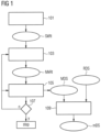
- Figure 1 is a schematic flow diagram of a method according to the invention for generating measurement data of an examination object by means of magnetic resonance fingerprinting.
- Parameters are loaded that describe a starting k-space trajectory SkRt along which generated echo signals are to be recorded as measurement data MDS (block 101).
- the loaded parameters thus contain Information about RF pulses to be radiated, gradients to be switched and readout times in their temporal sequence and relation to each other.
- the starting k-space trajectory described by the parameters can in particular be a Cartesian k-space trajectory or a radial or spiral k-space trajectory.
- a starting k-space trajectory SkRt can be specified for each segment.
- a starting k-space trajectory SkRt can also be determined for each respective segment, for example by rotation and/or translation in k-space starting from a common starting k-space trajectory SkRt.
- parameters for at least two starting k-space trajectories SkRt can therefore also be loaded in block 101, in particular parameters for one starting k-space trajectory SkRt per planned segment.
- a single starting k-space trajectory SkRt can be selected such that it alone does not completely sample the k-space according to Nyquist.
- the loaded starting k-space trajectories can be selected such that together they sample the k-space with a desired degree of completeness.
- a (still) total of the loaded starting k-space trajectories SkRt If incomplete sampling is selected, suitable supplementary methods such as partial Fourier methods, parallel acquisition methods or iterative reconstruction methods can be used to reconstruct image data from the MDS measurement data. This can also be the case with single-shot methods.
- At least one measurement k-space trajectory MkRt is created by fluctuating at least one parameter determining the course of the start k-space trajectory (block 103).
- the course of the measurement k-space trajectory MkRt for successive measurement points deviates in a different way from the course of the associated start k-space trajectory SkRt.
- the shape is changed in such a way that the measurement k-space trajectory MkRt in k-space no longer follows a stringent path like the original start k-space trajectory SkRt, but deviates erratically from the original start k-space trajectory SkRt.
- the fluctuation can occur by random variation of at least one parameter determining the course of the k-space trajectory within predetermined limits.
- the fluctuation is carried out in such a way that a spatial and/or temporal distribution of the noise contained in the recorded signals is as homogeneous as possible.
- framework conditions for the fluctuation can be specified which ensure that the respective measurement k-space trajectories MkRt in successive recordings of measurement data are so fluctuating and/or temporally distributed that any noise contained in the recordings is as incoherent as possible.
- Such framework conditions can also be weighed up and optimized, for example, between the extremes of maximum incoherence (and thus minimal artifacts) on the one hand and maximum quality of the obtained MRF parameter maps or MR images created from the measurement data or a minimum measurement time or acquisition length on the other. Optimization criteria for this can be determined using MR (base) images reconstructed from (subsampled) measurement data and/or obtained MRF parameter maps.
- the at least one parameter determining the course of the k-space trajectory that is fluctuated can, for example, be the starting angle of the starting k-space trajectory for radial or spiral starting k-space trajectories, so that the measuring k-space trajectories also have "curved" starting angles that do not, for example, depend linearly on a number of existing starting k-space trajectories and that would not be used as "intermediate angles" in conventional methods.
- the at least one parameter determining the course of the k-space trajectory and to be fluctuated can additionally or alternatively be the radius (over time) of the starting k-space trajectory that depends on the amplitude of the switched gradients.
- the at least one parameter determining the course of the k-space trajectory that is fluctuated can be a parameter of the switched gradients, in particular their amplitude, which determines the position of a measuring point in k-space.
- measurement data MDS can be recorded repeatedly in at least two repetitions based on a starting k-space trajectory SkRt, whereby for each repetition of the recording of the measurement data MDS, different measurement k-space trajectories MkRt are created starting from the starting k-space trajectory SkRt.
- SkRt a starting k-space trajectory
- Such a constant fluctuation of the k-space trajectories along which the measurement data is repeatedly recorded can achieve a particularly high degree of incoherence in the noise contained in the measurement data.
- measurement data MDS are recorded along the created measurement k-space trajectories MkRt (block 105), which are stored in a measurement data set.
- the measurement data MDS stored in the measurement data set can be compared with a reference data set RDS, for example an MRFdictionary, in order to create desired parameter maps mDS (block 109).
- RDS for example an MRFdictionary
- FIG 2 is an example of the temporal course of a parameter determining the course of a k-space trajectory, here the amplitude of the switched gradients.
- the change in the amplitude over time t of a first gradient G1 to be switched, which is applied in a first direction, e.g. in the readout direction, and of a second gradient G2 to be switched, which is applied in a second direction, e.g. in the phase encoding direction, which differs from the first direction, in particular is perpendicular to the first direction, is shown.
- Such a switching of gradients leads to a typical two-dimensional (2D), stringent, spiral k-space trajectory, as can be used as a starting k-space trajectory.
- the absolute value Abs_G of both gradients G1 and G2 is plotted.
- Such k-space trajectories as also used in the aforementioned article by Jiang et al., can serve as starting k-space trajectories for the method described herein.
- Figure 4 shows the result of a fluctuation of the amplitudes of the gradients G1 and G2 from Figure 2 .
- the gradient G1 became the gradient G1', which swings around the course of the gradient G1.
- the gradient G2 became the gradient G2', which swings around the course of the gradient G2.
- the absolute value Abs_G' of the two gradients G1' and G2 ⁇ also fluctuates erratically around the course of the original absolute value Abs_G.
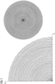
- Figure 6 are in Figure 7 Representations of measurement k-space trajectories, such as those obtained after fluctuation of parameters of the starting k-space trajectories from Figure 6 may have been created, shown once on the left in the overall view, and once on the right, enlarged.
- Each of the 48 starting k-space trajectories from Figure 6 was fluctuated in a unique way, so that the k-space points on a measuring k-space trajectory, at which successively Measurement data are recorded, have locally varying distances and/or the imaged field of view varies. Furthermore, a different fluctuation of the respective starting k-space trajectories ensures that noise contained in measurement data recorded along one of the measurement k-space trajectories is spatially distributed differently in each case. This avoids or at least reduces systematic errors in signal curves determined from the recorded measurement data.
- the order in which the measurement k-space trajectories created on the basis of the starting k-space trajectories are scanned one after the other can be optimized in such a way that any noise contained in the recorded measurement data is also distributed as differently as possible over time.
- the fluctuation of the starting k-space trajectories can also include an optimization of the order of the measurement k-space trajectories to be scanned one after the other.
- a fluctuation of other starting k-space trajectories e.g. radial or Cartesian, can be done analogously.
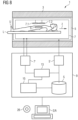
- Figure 8 schematically shows a magnetic resonance system 1 according to the invention.
- This comprises a magnet unit 3 for generating the basic magnetic field, a gradient unit 5 for generating the gradient fields, a high-frequency unit 7 for irradiating and receiving high-frequency signals and a control device 9 designed to carry out a method according to the invention.
- the high-frequency unit 7 can consist of several subunits, for example of several coils such as the schematically shown coils 7.1 and 7.2 or more coils, which are either only used to transmit high-frequency signals or only for receiving the triggered high-frequency signals or for both.
- the slice S represents an exemplary target volume of the examination object from which measurement data can be recorded.
- the control device 9 serves to control the magnetic resonance system and can in particular control the gradient unit 5 by means of a gradient controller 5' and the high-frequency unit 7 by means of a high-frequency transmission/reception controller 7'.
- the high-frequency unit 7 can comprise several channels on which signals can be transmitted or received.
- the center frequency of the high-frequency alternating field also referred to as the B1 field, must be close to the resonance frequency of the spins to be manipulated.
- controlled currents are applied to the RF coils in the high-frequency unit 7 by means of the high-frequency transmit/receive control 7'.
- the control device 9 also includes a fluctuation unit 15, with which k-space trajectories can be fluctuated and, if necessary, optimized framework conditions for the fluctuation can be defined.
- the control device 9 is designed overall to carry out a method according to the invention for avoiding artifacts when acquiring MR data of an examination object.
- a computing unit 13 included in the control device 9 is designed to carry out all the computing operations required for the necessary measurements and determinations. Intermediate results and results required for this purpose or determined in this process can be stored in a storage unit S of the control device 9.
- the units shown are not necessarily to be understood as physically separate units, but merely represent a subdivision into meaningful units, which can also be implemented, for example, in fewer or even in just one single physical unit.
- control commands can be sent to the magnetic resonance system, e.g. by a user, and/or results of the control device 9, such as image data, can be displayed.
- a method described herein can also be in the form of a computer program product which comprises a program and implements the described method on a control device 9 when it is executed on the control device 9.
- an electronically readable data carrier 26 with electronically readable control information stored thereon can be present, which comprise at least one such computer program product just described and are designed such that they carry out the described method when the data carrier 26 is used in a control device 9 of a magnetic resonance system 1.
Landscapes
- Physics & Mathematics (AREA)
- Condensed Matter Physics & Semiconductors (AREA)
- General Physics & Mathematics (AREA)
- High Energy & Nuclear Physics (AREA)
- Engineering & Computer Science (AREA)
- Signal Processing (AREA)
- Health & Medical Sciences (AREA)
- General Health & Medical Sciences (AREA)
- Nuclear Medicine, Radiotherapy & Molecular Imaging (AREA)
- Radiology & Medical Imaging (AREA)
- Magnetic Resonance Imaging Apparatus (AREA)
Claims (11)
- Procédé de prise d'empreintes digitales par résonnance magnétique pour la production de données de mesure d'un objet à examiner, dans lequel le procédé comprend les stades suivants :- charge de paramètres, qui décrivent une trajectoire (SkRt) dans l'espace k de début le long de laquelle des données (MDS) de mesure doivent être enregistrées,- établissement d'au moins une trajectoire (MkRt) dans l'espace k de mesure par fluctuation d'au moins un paramètre déterminant le tracé de la trajectoire (SkRt) dans l'espace k de début, de manière à ce que la trajectoire (MkRt) établie dans l'espace k de mesure s'étende d'une manière erratique,- enregistrement de données (MDS) de mesure le long de la trajectoire (MkRt) dans l'espace k de mesure,- répétition de l'enregistrement de données (MDS) de mesure le long de trajectoires (MkRt) établies dans l'espace k de mesure avec des paramètres de prise d'empreintes digitales différents jusqu'à ce que toutes les données (MDS) de mesure souhaitées soient enregistrées,- mise en mémoire des données (MDS) de mesure enregistrées en un ensemble de données de mesure,caractérisé en ce que
la fluctuation s'effectue de manière à ce qu'une répartition spatiale et/ou temporelle du bruit contenu dans les signaux enregistrés soit homogène le plus possible. - Procédé suivant la revendication 1, dans lequel la fluctuation s'effectue par des variations aléatoires à l'intérieur de valeurs limites données à l'avance du paramètre déterminant le tracé de la trajectoire (SkRt) dans l'espace k de début.
- Procédé suivant l'une des revendications précédentes, dans lequel on enregistre des données (MDS) de mesure de manière répétée en au moins deux répétitions sur la base d'une trajectoire (SkRt) dans l'espace k de début, dans lequel, pour chaque répétition, on établit l'enregistrement des données (MDS) de mesure respectivement de trajectoires (MkRt) dans l'espace k de mesure différentes, à partir de la trajectoire (SkRt) dans l'espace k de début.
- Procédé suivant l'une des revendications 1 à 2, dans lequel on charge des paramètres pour au moins deux trajectoires (SkRt) dans l'espace k de début, pour lesquelles on établit respectivement exactement une trajectoire (MkRt) dans l'espace k de mesure.
- Procédé suivant l'une des revendications précédentes, dans lequel une trajectoire (SkRt) dans l'espace de début sous-échantillonne à soi seule l'espace k suivant Nyquist.
- Procédé suivant l'une des revendications précédentes, dans lequel la trajectoire (SkRt) dans l'espace k de début et d'une trajectoire dans l'espace k radiale ou spirale et on fait fluctuer, comme paramètre, l'angle de début de la trajectoire (SkRt) dans l'espace k de début.
- Procédé suivant l'une des revendications précédentes, dans lequel la trajectoire (SkRt) dans l'espace k de début est une trajectoire dans l'espace k spiral et on fait fluctuer, comme paramètre, le rayon de la trajectoire dans l'espace k de début.
- Procédé d'établissement de cartes de paramètre au moyen d'une prise d'empreintes digitales par résonnance magnétique, dans lequel on compare des tracés de signal caractéristiques connus à au moins un tracé de signal d'au moins un point image, déterminé à partir d'un ensemble de données de résonnance magnétique établi selon un procédé suivant l'une des revendications 1 à 7, et dans lequel, sur la base des résultats de la comparaison, on affecte une valeur de paramètre au au moins un point image.
- Installation (1) de résonnance magnétique comprenant une unité (3) d'aimant, une unité (5) de gradient, une unité (7) de haute fréquence et un dispositif (9) de commande ayant une commande (7') d'émission/réception de haute fréquence et une unité (15) de fluctuation, dans laquelle le dispositif (9) de commande est constitué pour exécuter un procédé suivant l'une des revendications 1 à 8 sur l'installation (1) de résonnance magnétique.
- Programme d'ordinateur, qui peut être chargé directement dans la mémoire d'un dispositif (9) de commande d'une installation (1) de résonnance magnétique, comprenant des moyens de programme pour exécuter les stades du procédé suivant l'une des revendications 1 à 8, lorsque le programme est exécuté dans le dispositif (9) de commande de l'installation (1) de résonnance magnétique.
- Support de données, déchiffrable électroniquement, ayant des informations de commande, déchiffrables électroniquement, qui sont mises en mémoire et qui comprennent au moins un programme d'ordinateur suivant la revendication 10 et qui sont conformées de manière à ce qu'elles exécutent, lors de l'utilisation du support de données dans un dispositif (9) de commande d'une installation (1) de résonnance magnétique, un procédé suivant l'une des revendications 1 à 8.
Priority Applications (2)
| Application Number | Priority Date | Filing Date | Title |
|---|---|---|---|
| EP17191849.3A EP3457159B1 (fr) | 2017-09-19 | 2017-09-19 | Procédé de prise d'empreintes par résonance magnétique amélioré |
| US16/135,257 US20190086494A1 (en) | 2017-09-19 | 2018-09-19 | Magnetic resonance fingerprinting method and apparatus |
Applications Claiming Priority (1)
| Application Number | Priority Date | Filing Date | Title |
|---|---|---|---|
| EP17191849.3A EP3457159B1 (fr) | 2017-09-19 | 2017-09-19 | Procédé de prise d'empreintes par résonance magnétique amélioré |
Publications (3)
| Publication Number | Publication Date |
|---|---|
| EP3457159A1 EP3457159A1 (fr) | 2019-03-20 |
| EP3457159C0 EP3457159C0 (fr) | 2024-11-06 |
| EP3457159B1 true EP3457159B1 (fr) | 2024-11-06 |
Family
ID=59914371
Family Applications (1)
| Application Number | Title | Priority Date | Filing Date |
|---|---|---|---|
| EP17191849.3A Active EP3457159B1 (fr) | 2017-09-19 | 2017-09-19 | Procédé de prise d'empreintes par résonance magnétique amélioré |
Country Status (2)
| Country | Link |
|---|---|
| US (1) | US20190086494A1 (fr) |
| EP (1) | EP3457159B1 (fr) |
Families Citing this family (4)
| Publication number | Priority date | Publication date | Assignee | Title |
|---|---|---|---|---|
| DE102016217675A1 (de) * | 2016-09-15 | 2018-03-15 | Siemens Healthcare Gmbh | Verbesserte Erzeugung von Bildpunkt-Zeit-Serien eines Untersuchungsobjektes mittels Magnetresonanztechnik |
| US11630176B2 (en) * | 2019-12-26 | 2023-04-18 | The Brigham And Women's Hospital, Inc. | System and method for controlling physiological noise in functional magnetic resonance imaging |
| DE102020209383A1 (de) * | 2020-07-24 | 2022-01-27 | Siemens Healthcare Gmbh | Verfahren zur Aufnahme von Messdaten mittels einer Magnetresonanzanlage mit einer Korrektur der verwendeten k-Raumtrajektorien |
| DE102020209382A1 (de) * | 2020-07-24 | 2022-01-27 | Siemens Healthcare Gmbh | Verfahren zur Aufnahme von Messdaten mittels einer Magnetresonanzanlage mit einer Korrektur der verwendeten k-Raumtrajektorien |
Family Cites Families (12)
| Publication number | Priority date | Publication date | Assignee | Title |
|---|---|---|---|---|
| US6414487B1 (en) * | 2000-11-22 | 2002-07-02 | Philips Medical Systems (Cleveland), Inc. | Time and memory optimized method of acquiring and reconstructing multi-shot 3D MRI data |
| US7791338B2 (en) * | 2007-09-07 | 2010-09-07 | The Board Of Trustees Of The Leland Stanford Junior University | MRI method of determining time-optimal gradient waveforms with gradient amplitude as a function of arc-length in k-space |
| GB2498943A (en) * | 2012-01-31 | 2013-08-07 | Ibm | Evaluating and optimizing a trajectory function |
| DE102012222149B4 (de) * | 2012-12-04 | 2014-09-18 | Siemens Aktiengesellschaft | Verfahren zur Erzeugung von Magnetresonanzmessdaten |
| WO2015116894A1 (fr) * | 2014-01-31 | 2015-08-06 | The General Hospital Corporation | Irm à tranches multiples simultanées à codage de gradient aléatoire |
| DE102014203067A1 (de) * | 2014-02-20 | 2015-08-20 | Siemens Aktiengesellschaft | Verfahren zur Aufnahme von Magnetresonanzdaten eines Untersuchungsobjekts und Magnetresonanzeinrichtung |
| DE102014203068B4 (de) * | 2014-02-20 | 2015-11-26 | Siemens Aktiengesellschaft | Pseudo-zufällige Erfassung von MR-Daten eines zweidimensionalen Volumenabschnitts |
| WO2015138941A1 (fr) * | 2014-03-14 | 2015-09-17 | The General Hospital Corporation | Système et procédé d'empreinte de résonance magnétique |
| US10466321B2 (en) * | 2015-11-12 | 2019-11-05 | The General Hospital Corporation | Systems and methods for efficient trajectory optimization in magnetic resonance fingerprinting |
| US20170234951A1 (en) * | 2016-02-11 | 2017-08-17 | The General Hospital Corporation | Systems and methods for improved reconstruction of magnetic resonance fingerprinting data with low-rank methods |
| US10222441B2 (en) * | 2016-04-03 | 2019-03-05 | Q Bio, Inc. | Tensor field mapping |
| US10816625B2 (en) * | 2016-04-26 | 2020-10-27 | Koninklijke Philips N.V. | Silent 3D magnetic resonance fingerprinting |
-
2017
- 2017-09-19 EP EP17191849.3A patent/EP3457159B1/fr active Active
-
2018
- 2018-09-19 US US16/135,257 patent/US20190086494A1/en not_active Abandoned
Also Published As
| Publication number | Publication date |
|---|---|
| EP3457159C0 (fr) | 2024-11-06 |
| US20190086494A1 (en) | 2019-03-21 |
| EP3457159A1 (fr) | 2019-03-20 |
Similar Documents
| Publication | Publication Date | Title |
|---|---|---|
| EP3299833B1 (fr) | Génération améliorée des séries chronologiques de points image d'un objet examiné au moyen de la technique de résonance magnétique | |
| DE102008014060B4 (de) | Verfahren zur Bestimmung einer Phasenlage einer Magnetisierung und Magnetresonanzanlage | |
| DE102014214844B4 (de) | Verfahren und Magnetresonanzanlage zum Erfassen von MR-Daten | |
| DE102014203068B4 (de) | Pseudo-zufällige Erfassung von MR-Daten eines zweidimensionalen Volumenabschnitts | |
| DE102011083871B4 (de) | Anpassung der Grundfrequenz eines HF-Anregungspulses bei der nicht-selektiven Anregung von Kernspinsignalen in einem Untersuchungsobjekt | |
| EP3457159B1 (fr) | Procédé de prise d'empreintes par résonance magnétique amélioré | |
| DE102011083619A1 (de) | Verfahren zur Erzeugung einer Serie von MR-Bildern zur Überwachung einer Position eines in einem Untersuchungsgebiet befindlichen Interventionsgeräts, Magnetresonanzanlage, Computerprogrammprodukt und elektronisch lesbarer Datenträger | |
| DE102015204483A1 (de) | Magnetresonanz-Vorschau-Abbildung | |
| DE102013217617B4 (de) | Steuerungsverfahren zur Kontrolle einer Datenerfassung von Magnetresonanz-Bilddaten | |
| DE102018209584A1 (de) | Magnetresonanz-Fingerprinting-Verfahren | |
| DE102020209382A1 (de) | Verfahren zur Aufnahme von Messdaten mittels einer Magnetresonanzanlage mit einer Korrektur der verwendeten k-Raumtrajektorien | |
| DE102014222495A1 (de) | Korrektur von Magnetresonanz-Bildaufnahmen mit Hilfe konvertierter Feldkarten | |
| DE102013207438A1 (de) | Verfahren zur Erstellung von Bilddatensätzen eines Untersuchungsobjekts mittels eines Magnetresonanzgeräts | |
| DE102011082669A1 (de) | Hyperintense Darstellung von Bereichen im Umfeld von Dipolfeldern mittels MRI | |
| DE102010041659B4 (de) | Erzeugung eines optimierten MR-Bildes eines Untersuchungsobjekts durch Einstrahlen einer mindestens zwei HF-Pulse umfassenden Pulsfolge | |
| DE102016201458B4 (de) | Radiales Erfassen von MR-Daten zur Vermeidung von Artefakten | |
| DE102014204995B4 (de) | Verfahren und Magnetresonanzanlage zur Fettsättigung | |
| DE102012216711A1 (de) | Erstellung einer Folge von Bilddatensätzen eines in einem Messvolumen einer Magnetresonanzanlage befindlichen Abbildungsgebiets | |
| DE102012210324B4 (de) | Anpassung der Echozuglänge bei der Erfassung von MR-Daten in einem vorbestimmten Volumenabschnitt | |
| DE102011083890B4 (de) | MR-Bildgebung mit variabler Anzahl von Präparationspulsen | |
| DE102018205867A1 (de) | Verfahren und Vorrichtung zur Erstellung einer Pulssequenz zur Ansteuerung eines Magnetresonanztomographie-Systems | |
| EP3572824A1 (fr) | Mesure de résonance magnétique insensible à la résistance à l'état bloqué avec un gradient de déphasage | |
| DE102013223191B4 (de) | Erfassen von MR-Daten einer Schicht eines Volumenabschnitts mit einer variablen Anzahl von Phasenkodierschritten | |
| DE102012219920B4 (de) | Doppelecho-MR-Bildgebung mit vollständigen und unvollständigen Rohdatensätzen | |
| EP3629048A1 (fr) | Prise d'empreintes à résonance magnétique à champs faible |
Legal Events
| Date | Code | Title | Description |
|---|---|---|---|
| PUAI | Public reference made under article 153(3) epc to a published international application that has entered the european phase |
Free format text: ORIGINAL CODE: 0009012 |
|
| STAA | Information on the status of an ep patent application or granted ep patent |
Free format text: STATUS: THE APPLICATION HAS BEEN PUBLISHED |
|
| AK | Designated contracting states |
Kind code of ref document: A1 Designated state(s): AL AT BE BG CH CY CZ DE DK EE ES FI FR GB GR HR HU IE IS IT LI LT LU LV MC MK MT NL NO PL PT RO RS SE SI SK SM TR |
|
| AX | Request for extension of the european patent |
Extension state: BA ME |
|
| STAA | Information on the status of an ep patent application or granted ep patent |
Free format text: STATUS: REQUEST FOR EXAMINATION WAS MADE |
|
| 17P | Request for examination filed |
Effective date: 20190920 |
|
| RBV | Designated contracting states (corrected) |
Designated state(s): AL AT BE BG CH CY CZ DE DK EE ES FI FR GB GR HR HU IE IS IT LI LT LU LV MC MK MT NL NO PL PT RO RS SE SI SK SM TR |
|
| STAA | Information on the status of an ep patent application or granted ep patent |
Free format text: STATUS: EXAMINATION IS IN PROGRESS |
|
| 17Q | First examination report despatched |
Effective date: 20220131 |
|
| RAP1 | Party data changed (applicant data changed or rights of an application transferred) |
Owner name: SIEMENS HEALTHINEERS AG |
|
| GRAP | Despatch of communication of intention to grant a patent |
Free format text: ORIGINAL CODE: EPIDOSNIGR1 |
|
| STAA | Information on the status of an ep patent application or granted ep patent |
Free format text: STATUS: GRANT OF PATENT IS INTENDED |
|
| RIC1 | Information provided on ipc code assigned before grant |
Ipc: G01R 33/50 20060101ALN20240611BHEP Ipc: G01R 33/56 20060101ALI20240611BHEP Ipc: G01R 33/48 20060101AFI20240611BHEP |
|
| INTG | Intention to grant announced |
Effective date: 20240701 |
|
| GRAS | Grant fee paid |
Free format text: ORIGINAL CODE: EPIDOSNIGR3 |
|
| GRAA | (expected) grant |
Free format text: ORIGINAL CODE: 0009210 |
|
| STAA | Information on the status of an ep patent application or granted ep patent |
Free format text: STATUS: THE PATENT HAS BEEN GRANTED |
|
| AK | Designated contracting states |
Kind code of ref document: B1 Designated state(s): AL AT BE BG CH CY CZ DE DK EE ES FI FR GB GR HR HU IE IS IT LI LT LU LV MC MK MT NL NO PL PT RO RS SE SI SK SM TR |
|
| REG | Reference to a national code |
Ref country code: GB Ref legal event code: FG4D Free format text: NOT ENGLISH |
|
| REG | Reference to a national code |
Ref country code: CH Ref legal event code: EP |
|
| REG | Reference to a national code |
Ref country code: DE Ref legal event code: R096 Ref document number: 502017016542 Country of ref document: DE |
|
| REG | Reference to a national code |
Ref country code: IE Ref legal event code: FG4D Free format text: LANGUAGE OF EP DOCUMENT: GERMAN |
|
| U01 | Request for unitary effect filed |
Effective date: 20241106 |
|
| U07 | Unitary effect registered |
Designated state(s): AT BE BG DE DK EE FI FR IT LT LU LV MT NL PT RO SE SI Effective date: 20241113 |
|
| PG25 | Lapsed in a contracting state [announced via postgrant information from national office to epo] |
Ref country code: HR Free format text: LAPSE BECAUSE OF FAILURE TO SUBMIT A TRANSLATION OF THE DESCRIPTION OR TO PAY THE FEE WITHIN THE PRESCRIBED TIME-LIMIT Effective date: 20241106 Ref country code: IS Free format text: LAPSE BECAUSE OF FAILURE TO SUBMIT A TRANSLATION OF THE DESCRIPTION OR TO PAY THE FEE WITHIN THE PRESCRIBED TIME-LIMIT Effective date: 20250306 |
|
| PG25 | Lapsed in a contracting state [announced via postgrant information from national office to epo] |
Ref country code: ES Free format text: LAPSE BECAUSE OF FAILURE TO SUBMIT A TRANSLATION OF THE DESCRIPTION OR TO PAY THE FEE WITHIN THE PRESCRIBED TIME-LIMIT Effective date: 20241106 |
|
| PG25 | Lapsed in a contracting state [announced via postgrant information from national office to epo] |
Ref country code: NO Free format text: LAPSE BECAUSE OF FAILURE TO SUBMIT A TRANSLATION OF THE DESCRIPTION OR TO PAY THE FEE WITHIN THE PRESCRIBED TIME-LIMIT Effective date: 20250206 |
|
| PG25 | Lapsed in a contracting state [announced via postgrant information from national office to epo] |
Ref country code: GR Free format text: LAPSE BECAUSE OF FAILURE TO SUBMIT A TRANSLATION OF THE DESCRIPTION OR TO PAY THE FEE WITHIN THE PRESCRIBED TIME-LIMIT Effective date: 20250207 |
|
| PG25 | Lapsed in a contracting state [announced via postgrant information from national office to epo] |
Ref country code: PL Free format text: LAPSE BECAUSE OF FAILURE TO SUBMIT A TRANSLATION OF THE DESCRIPTION OR TO PAY THE FEE WITHIN THE PRESCRIBED TIME-LIMIT Effective date: 20241106 |
|
| PG25 | Lapsed in a contracting state [announced via postgrant information from national office to epo] |
Ref country code: RS Free format text: LAPSE BECAUSE OF FAILURE TO SUBMIT A TRANSLATION OF THE DESCRIPTION OR TO PAY THE FEE WITHIN THE PRESCRIBED TIME-LIMIT Effective date: 20250206 |
|
| PG25 | Lapsed in a contracting state [announced via postgrant information from national office to epo] |
Ref country code: SM Free format text: LAPSE BECAUSE OF FAILURE TO SUBMIT A TRANSLATION OF THE DESCRIPTION OR TO PAY THE FEE WITHIN THE PRESCRIBED TIME-LIMIT Effective date: 20241106 |
|
| PG25 | Lapsed in a contracting state [announced via postgrant information from national office to epo] |
Ref country code: SK Free format text: LAPSE BECAUSE OF FAILURE TO SUBMIT A TRANSLATION OF THE DESCRIPTION OR TO PAY THE FEE WITHIN THE PRESCRIBED TIME-LIMIT Effective date: 20241106 |
|
| PG25 | Lapsed in a contracting state [announced via postgrant information from national office to epo] |
Ref country code: CZ Free format text: LAPSE BECAUSE OF FAILURE TO SUBMIT A TRANSLATION OF THE DESCRIPTION OR TO PAY THE FEE WITHIN THE PRESCRIBED TIME-LIMIT Effective date: 20241106 |
|
| PLBE | No opposition filed within time limit |
Free format text: ORIGINAL CODE: 0009261 |
|
| STAA | Information on the status of an ep patent application or granted ep patent |
Free format text: STATUS: NO OPPOSITION FILED WITHIN TIME LIMIT |
|
| 26N | No opposition filed |
Effective date: 20250807 |
|
| U20 | Renewal fee for the european patent with unitary effect paid |
Year of fee payment: 9 Effective date: 20250919 |
|
| PGFP | Annual fee paid to national office [announced via postgrant information from national office to epo] |
Ref country code: GB Payment date: 20251002 Year of fee payment: 9 |
|
| REG | Reference to a national code |
Ref country code: CH Ref legal event code: H13 Free format text: ST27 STATUS EVENT CODE: U-0-0-H10-H13 (AS PROVIDED BY THE NATIONAL OFFICE) Effective date: 20260425 |