EP3457313B1 - Verfahren und vorrichtung zur abbildung einer referenzansicht mit einem kamerabild - Google Patents
Verfahren und vorrichtung zur abbildung einer referenzansicht mit einem kamerabild Download PDFInfo
- Publication number
- EP3457313B1 EP3457313B1 EP17190979.9A EP17190979A EP3457313B1 EP 3457313 B1 EP3457313 B1 EP 3457313B1 EP 17190979 A EP17190979 A EP 17190979A EP 3457313 B1 EP3457313 B1 EP 3457313B1
- Authority
- EP
- European Patent Office
- Prior art keywords
- camera image
- field lines
- field
- camera
- playing field
- Prior art date
- Legal status (The legal status is an assumption and is not a legal conclusion. Google has not performed a legal analysis and makes no representation as to the accuracy of the status listed.)
- Active
Links
Images



Classifications
-
- G—PHYSICS
- G06—COMPUTING OR CALCULATING; COUNTING
- G06V—IMAGE OR VIDEO RECOGNITION OR UNDERSTANDING
- G06V40/00—Recognition of biometric, human-related or animal-related patterns in image or video data
- G06V40/20—Movements or behaviour, e.g. gesture recognition
- G06V40/23—Recognition of whole body movements, e.g. for sport training
-
- G—PHYSICS
- G06—COMPUTING OR CALCULATING; COUNTING
- G06T—IMAGE DATA PROCESSING OR GENERATION, IN GENERAL
- G06T7/00—Image analysis
- G06T7/80—Analysis of captured images to determine intrinsic or extrinsic camera parameters, i.e. camera calibration
-
- G—PHYSICS
- G06—COMPUTING OR CALCULATING; COUNTING
- G06V—IMAGE OR VIDEO RECOGNITION OR UNDERSTANDING
- G06V20/00—Scenes; Scene-specific elements
- G06V20/40—Scenes; Scene-specific elements in video content
- G06V20/41—Higher-level, semantic clustering, classification or understanding of video scenes, e.g. detection, labelling or Markovian modelling of sport events or news items
- G06V20/42—Higher-level, semantic clustering, classification or understanding of video scenes, e.g. detection, labelling or Markovian modelling of sport events or news items of sport video content
-
- G—PHYSICS
- G06—COMPUTING OR CALCULATING; COUNTING
- G06T—IMAGE DATA PROCESSING OR GENERATION, IN GENERAL
- G06T2207/00—Indexing scheme for image analysis or image enhancement
- G06T2207/30—Subject of image; Context of image processing
- G06T2207/30221—Sports video; Sports image
- G06T2207/30228—Playing field
-
- G—PHYSICS
- G06—COMPUTING OR CALCULATING; COUNTING
- G06V—IMAGE OR VIDEO RECOGNITION OR UNDERSTANDING
- G06V10/00—Arrangements for image or video recognition or understanding
- G06V10/20—Image preprocessing
- G06V10/24—Aligning, centring, orientation detection or correction of the image
- G06V10/247—Aligning, centring, orientation detection or correction of the image by affine transforms, e.g. correction due to perspective effects; Quadrilaterals, e.g. trapezoids
Definitions
- the present disclosure relates to a method for automatically mapping a reference view of a playing field containing field lines with a camera image.
- the disclosure also relates to an apparatus for implementing the method.
- the method and apparatus are particularly relevant for live broadcasts.
- US 2003/0049590 A1 discloses a system for determining the position of all players on a playing field.
- the system is capable of determining, in real time, from optical data a position of a playing ball and positions of players from an offensive team and from a defensive team.
- Two surveillance instruments, such as cameras, survey the playing field and are connected to a computer.
- the computer algorithms identify objects, colors and shapes and thus determine in real time the positions of the ball and the players of the offensive and defensive team.
- EP2034440 A2 discloses a method of calculating a transform matrix for transforming points in a model of an object to an image of the object captured by a camera. This method is applied in particular to images of a football match.
- US 2009/0060352 A1 describes a method for detecting and classifying offside events in a soccer game. The method builds on ball tracking and detection as well as on determining ball dynamics. In addition to that, players are detected. For implementing the ball tracking feature it is suggested to utilize an artificial neural network, which is trained to recognize the ball. For illustrating a potential off-side position a bar parallel to the goal line is positioned manually by an operator.
- the present disclosure suggests a method for automatically mapping a reference view of a playing field containing field lines with a camera image.
- the invention is set out in the appended claims.
- the proposed technique automates the estimation of the homography, which is a kind of geometric transformation between pairs of two-dimensional images.
- Homography maps a reference view of a sports field, as seen from a given, known a priori, viewpoint (e.g. a "top” view) to images acquired by a camera pointed at the same sport field, and vice-versa.
- the method is applicable to one or more camera images corresponding to one or more camera views each one covering the complete playing field or only a fraction of the playing field.
- the suggested method enables automatically detecting predefined positions on the playing field and thus enables to calculate the geometric transformation of the playing field caused by a specific camera view.
- This geometric transformation determines the way how an additional auxiliary line like an offside line has to be inserted into the camera image such that the user has the impression that the line is painted on the grass of the playing field.
- the advantage of the suggested method is that the classification of the predefined positions on the playing field in the calculation of the geometric transformation is performed automatically without human intervention. The operator of a live broadcast covering for example sports events is significantly unburdened by this automatic process.
- the detected field lines are very useful for an assessment of the quality of the geometric transformation because a comparison of the detected field lines and calculated field lines enables the assessment of the fidelity of the geometric transformation.
- An embodiment takes benefit from having two sets of field lines available and further comprises adapting parameters of the geometric transformation for minimizing the differences between the detected field lines and the calculated field lines. In this way a refinement of the geometric transformation is achievable. Once it is no longer possible to further minimize the differences between the detected field lines and calculated field lines the corresponding parameters set of the geometric transformation is used to calculate the position and orientation of the additional line that is to be inserted into the camera image.
- the inserted line can be an offside line. Since the geometric transformation, which is caused by the camera perspective, is known, it is possible to insert the line such that a viewer in front of a TV screen has the impression that the line is painted on the grass of the playing field. All necessary connections and calculations are performed automatically real-time.
- an apparatus for automatic mapping a reference view of a playing field containing field lines with a camera image of a live broadcast production covering a ballgame on a playing field with field lines.
- the present disclosure suggests a software containing program code, which, when executed by a processor, performs a method according to the first aspect of the present disclosure.
- the present disclosure relates to mapping of a reference view of a playing field for sports such as soccer, basketball, US football, tennis and others.
- the reference view is a view on the playing field from a known view point, for instance from a top view.
- the present disclosure suggests a method for mapping the reference view to images acquired by a camera pointed at the same sport field, and vice-versa.
- the mapping permits to determine an estimate for a geometric transformation also known as homography between the pairs of the two dimensional images, namely the reference view and the camera image.
- the geometric transformation is known, it enables the insertion of graphical objects into the camera image in compliance with the perspective of the camera view, e.g. it is possible to display an offside line in a soccer game, player trajectories, advertising, scoreboard, etc. as if these objects were "painted on the grass" of the playing field.
- FIG. 1A an attack situation of a soccer team is shown.
- the goal of the defensive team is on the right side in Fig. 1A .
- An offensive player 101 just has the ball in the situation shown in Fig. 1A .
- a second attacking player 102 is marked by two defenders 103, 104. From the view shown in Fig. 1A it is difficult to say whether this second attacking player 102 is offside or not, i.e. whether he is closer to the goal line of the defensive team than any other defender with the exception of the goalkeeper of the defensive team.
- a linesman 106 runs together with the defender 104, who is closest to the goal line, in order to be able to identify an offside situation.
- the linesman tries to be on the same level as the defender 104 with regard to the goal line to have a view on the position of the defender which is not falsified by a parallax error. If the linesman 106 falls behind the position of the defender 104 or advances with regard to that position there is a risk that the linesmen makes an erroneous decision.
- a line is inserted between offside and fair play.
- the line is shown as a straight line 107 in Fig. 1B .
- the offside line 107 is displayed on a screen of a TV as if it was painted on the grass of the playing field. It is not straightforward to achieve this effect because the vanishing point of the camera image depends on the perspective of the camera on the playing field.
- the present disclosure therefore, aims at replacing manual interventions by automatic processes when inserting an offside line in the camera image.
- Fig. 2 shows a block diagram of an apparatus 200 for achieving this goal.
- a camera 201 captures images in a football stadium. For the sake of simplicity only a single camera 201 is shown in Fig. 2 . But in reality, there are for example 8 to 16 cameras distributed around the playing field to make sure that there is always one camera that has a good shot at an interesting scene anywhere on the playing field. The camera images of multiple cameras are processed in parallel.
- the camera 201 feeds the image data into a data connection 202 that transmits the data to a video processor 203, a first neural network (AI1) 204 and a second neural network (AI2) 206.
- the block diagram is a simplification of the broadcast equipment for producing life broadcast programs.
- the broadcast equipment may also include storage devices, routers, digital video effect devices, character generators etc. All these devices are not shown in Fig. 2 because they are not relevant to understand the present disclosure.
- the data connection 202 transmits the image frames from the camera 201 in synchronized fashion to the video processor 203 and to neural networks 204 and 206, i.e. every image frame arrives at the same time at all three devices.
- the first neural network 204 automatically classifies each pixel of the camera image into a plurality of classes, wherein the classes correspond to predefined locations on the playing field.
- the predefined locations are intersections of field lines on the playing field.
- Fig. 3A shows intersections of field lines on a soccer field. Each intersection is marked with a circle having an index number 1 to 31 in the circle.
- the first neural network 204 has been trained to detect corresponding locations in the camera image as it is shown in Fig. 3B .
- the first neural network 204 generates for each pixel in the camera image a triplet composed of the geometric position of the pixel in the image and a class identifying whether the pixel corresponds to one of the predefined locations: (x,y,class). These triplets are output to the video processor 203 which calculates a first estimate of a geometric transformation that transforms the top view of the playing field into the playing field captured by the camera.
- the known geometric transformation enables the video processor 203 to calculate field lines in the camera image.
- the second neural network 206 has been trained to detect the field lines in the camera image and outputs the coordinates of the field lines to the video processor 203.
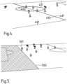
- the result is shown in Fig. 4 as a composite image where field lines captured by the camera 201 are shown as solid lines 401 and the field lines calculated according to the first estimate of the geometric transition are shown as dashed lines 402.
- Fig. 4 there are deviations between the field lines 401 and 402. For better illustration the deviations are exaggerated, i.e. in reality the deviations are smaller.
- the video processor 203 compares the positions of the detected field 401 lines in the camera image with the calculated field lines 402 and refines the geometric transformation to minimize the differences and/or deviations between the two sets of field lines.
- the geometric transformation has eight degrees of freedom (parameters). Finding a refined geometric transformation consists in finding the set of parameter values that causes the calculated lines 402 in the composite image to overlap as good as possible the field lines 401 detected by neural network 206. According to the approach of the present disclosure the first estimate mentioned above is used as a starting point. Subsequently, the 8-dimensional parameter space is explored. This exploration is conducted in an iterative fashion. At each iteration one parameter in the parameter space is incremented. At each iteration, a step of fixed (given) extent in the 8-dimensional parameter space is made. The orientation chosen for this step is the one that increases the most the overlap between the calculated field lines 402 and the detected field lines 401. This process stops when it is no longer possible to make a step that increases the overlap. Such procedure is known in the literature as "iterative gradient descent".
- the offside line is computed and inserted into the camera image by the video processor 203 using the refined geometric transformation.
- the offside line is still manually positioned by an operator, because the operator decides at which distance from the goal line of the defensive team the offside line 107 is drawn in the camera image.
- all preparation steps enabling generating an offside line in the correct perspective for each camera image is performed automatically.
- commercially available processors are fast enough to perform all necessary computations in real time for example within 2 ms, which is the equivalent of processing 500 frames per second.
- the correct geometric transformation is available in real time and an offside line can be inserted into each camera frame in compliance with the right perspective. The only remaining task for the operator is to position the offside line.
- the operator is also unburdened from positioning the offside line.
- a third neural network 207 receives the camera images in synchronicity like the neural networks 204, 206.
- the neural network 207 is trained for detecting players on the playing field. This includes distinguishing the players of the two teams and their respective positions. Therefore, the neural network 207 is capable of detecting the position of the defence player who is closest to the goal line of his team.
- the position data is output as coordinates of the camera image to the video processor 203.
- the video processor 203 utilizes this information to position the offside line as illustrated in Fig. 5 .
- the defence player who is closest to the goal line of his team is referenced as 501.
- the hatched area on the left side of line 502 in Fig. 5 indicates the offside in the moment of the game shown in Fig. 5 . Consequently, at any moment the right position and perspective of the offside line is available in real-time and can be inserted into every camera image frame.
- the offside line is only interesting in some scenes of the game and rather disturbing during other scenes. Therefore, in one embodiment the operator controls the insertion of the offside line by activating a button 601 on a control panel 602 shown in Fig. 6 without the need to provide any further inputs because the video processor 203 of apparatus 200 has already all necessary information to position and orient the offside line such that the viewer gets the desired impression that the offside line is drawn on the grass of the playing field.
- Fig. 7 exhibits a flow diagram illustrating the steps of the method according to the present disclosure.
- step S1 camera images are received and transmitted via a data connection or network 202.
- step S2 a neural network 204 classifies each pixel of each camera image to determine whether the pixel belongs to a predefined position such as an intersection of field lines on a playing field.
- the result of processing step S2 is a data triplet containing the geometric position of the pixel in the camera image and the corresponding class information.
- the data triplet is provided to a video processor 203 that uses in step S3 the data triplet to calculate the geometric transformation which is associated with the camera perspective capturing the playing field.
- step S4 the video processor 203 receives information about a position of the offside line.
- the information is provided as manual input by an operator.
- the information about the position of the offside line is automatically determined or by the neural network 207, which automatically determines the positions of all players on the playing field.
- the neural network 207 can easily detect an offside position by applying a simple rule.
- the video processor 203 uses the information about the position of the offside line to insert the offside line 107 at the right position into the camera image in compliance with the camera perspective. The user gets the impression that the offside line is drawn with paint on the grass of the playing field.
- the offside line is only exemplary for other graphical objects, which are inserted into the camera image and which are of interest to the viewer such as player trajectories, player names, advertising, scoreboard, etc.
- the method according to the present disclosure only performs steps S1 to S3, i.e. calculates the geometric transformation to make it available for other purposes as it is explained in greater detail further below.
- the method of the present disclosure and more particularly the geometric transformation works in both directions between the reference view and the camera image, i.e. it is possible to map a position in a camera image with the corresponding position in the reference view.
- This aspect is interesting e.g. for live broadcasts of sports events when a plurality of cameras are installed in a stadium. Obviously, the cameras have different views on the scenes on the playing field. It occurs that in an important scene a single camera image does not display all key players but only in two or more camera images shot by different cameras having different views or perspectives on the playing field.
- the suggested method allows reconciling observations made by multiple cameras pointed at the same event by projecting all of camera images on the reference view.
- the reference view represents a single tactical view including the position of players, balls etc.
- the projection is performed by video processor.
- the neural network 207 is capable of tracking all players on the playing field in the received camera images.
- the video processor 203 receives this information and is provided with an automated player detection functionality, which is configured to indicate the positions of all players in the reference view.
- the apparatus 200 also implements an automated player detection system.
- Fig. 8 The output of the automated player detection system is displayed in Fig. 8 showing a top view on the playing field.
- a starting point of a player at the beginning of the important scene is indicated with a cross 801.
- a line 802 shows the trajectory of the player to an end point 803 of the player at the end of the important scene.
- the operator can select on the control panel 602 additional players if he finds their trajectories are also interesting for analysing the important scene.
- any information that is easily represented in the tactical view e.g. the offside line
- Figures 9A and 9B illustrate the reversibility of the geometric transformation.
- Fig. 9A shows a camera image or camera view on a playing field.
- Fig. 9A displays players 901 of an offensive team, players of a defensive team 902, an offside line 903 and some predefined locations 904.
- Fig. 9B shows a top view or tactical view corresponding to the camera view of Fig. 9A .
- the positions of the players 901, 902, the offside line 903 and the predefined locations 904 are shown at their corresponding positions in the top view.
- Lines 906 visualize the aperture of a camera that has taken the image shown in Fig. 9A .
- Arrows 907 symbolize the reversible geometric transition between the views.
- the offside line 903 is an example of a graphical object that can easily be positioned in the top view in Fig. 9B . From there it is transferred in the right perspective into the camera image shown in Fig. 9A .
- the operator can check if graphical objects to be inserted into the camera view are obstructed by players. If necessary, he can move the graphical object to a better suited position.
- the method and apparatus of the present disclosure enable augmented reality in live broadcasts, in particular in live broadcasts of sports events.
- a single unit or device may perform the functions of several elements set forth in the claims.
Landscapes
- Engineering & Computer Science (AREA)
- Theoretical Computer Science (AREA)
- Physics & Mathematics (AREA)
- General Physics & Mathematics (AREA)
- Multimedia (AREA)
- Computer Vision & Pattern Recognition (AREA)
- Health & Medical Sciences (AREA)
- Computational Linguistics (AREA)
- Software Systems (AREA)
- General Health & Medical Sciences (AREA)
- Psychiatry (AREA)
- Social Psychology (AREA)
- Human Computer Interaction (AREA)
- Image Analysis (AREA)
- Studio Devices (AREA)
Claims (9)
- Verfahren zum automatischen Abbilden einer Referenzansicht eines Spielfelds, das Feldlinien enthält, mit einem Kamerabild, wobei das Verfahren umfasst:- Bestimmen im Voraus definierter Orte auf dem Spielfeld in der Referenzansicht;- Empfangen des Kamerabilds von einer Kamera (201);- Klassifizieren von Schnittpunkten der Feldlinien mit einem ersten neuronalen Netz (204) an im Voraus definierten Positionen auf dem Spielfeld, um automatisch jedes Pixel des Kamerabilds in mehrere Klassen zu klassifizieren, wobei die Klassen den im Voraus definierten Orten in der Referenzansicht auf dem Spielfeld entsprechen;- Detektieren der Feldlinien (401) in dem Kamerabild mit einem zweiten neuronalen Netz (206);- Empfangen der Ausgabe des ersten neuronalen Netzes (204) und einer bekannten Geometrie des Spielfelds und der Feldlinien darauf, um eine geometrische Transformation zu berechnen, die definiert, wie die Geometrie des Spielfelds durch die Perspektive des Kamerabilds transformiert wird, und um Feldlinien in der Kameraansicht zu berechnen;- Verfeinern der geometrischen Transformation durch Minimieren von Abweichungen zwischen den berechneten Feldlinien und den detektierten Feldlinien;- Detektieren von Positionen von Spielern und Unterscheiden ihrer jeweiligen Mannschaften mit einem dritten neuronalen Netz (207);- automatisches Positionieren einer Abseitslinie (502) in dem Kamerabild unter Verwendung der verfeinerten geometrischen Transformation in Übereinstimmung mit der detektierten Position eines der Spieler (501), wobei die Abseitslinie in dem Kamerabild angezeigt werden kann.
- Verfahren nach Anspruch 1, das ferner umfasst:
Einfügen der Abseitslinie (107; 502; 903) in das Kamerabild gemäß der berechneten geometrischen Transformation. - Verfahren nach Anspruch 1 oder 2, das ferner umfasst:- Berechnen von Feldlinien (402) auf der Grundlage der geometrischen Transformation;- Einfügen der berechneten Feldlinien (402) in das Kamerabild; und- Anpassen von Parametern der geometrischen Transformation zum Minimieren der Unterschiede zwischen den detektierten Feldlinien (401) und den berechneten Feldlinien (402).
- Verfahren nach einem der vorhergehenden Ansprüche, das ferner umfasst:- Anwenden der geometrischen Transformation auf ein oder mehrere Kamerabilder, um das eine oder mehrere Kamerabilder auf die Referenzansicht des Spielfelds abzubilden.
- Verfahren nach Anspruch 4, das ferner umfasst:- Angeben eines Anfangspunkts (801), eines Endpunkts (803) und/oder einer Bewegungsbahn (802) eines ausgewählten Spielers in der Referenzansicht des Spielfelds.
- Vorrichtung zum automatischen Abbilden einer Referenzansicht eines Spielfelds, das Feldlinien enthält, mit einem Kamerabild einer Livesendungsproduktion, die von einem Ballspiel auf einem Spielfeld mit Feldlinien berichtet, wobei die Vorrichtung umfasst:- ein erstes neuronales Netz (204), das in der Vorrichtung implementiert wird und das zum automatischen Klassifizieren jedes Pixels des Kamerabilds in mehrere Klassen trainiert wird, wobei die Klassen im Voraus definierten Orten in der Referenzansicht des Spielfelds entsprechen, wobei das erste neuronale Netz (204) eine Ausgabe erzeugt, die einen Ort jedes Pixels in dem Kamerabild und zu welcher Klasse es gehört, identifiziert;- einen Videoprozessor (203), der die Ausgabe des ersten neuronalen Netzes (204) und eine bekannte Geometrie des Spielfelds und der Feldlinien darauf empfängt, wobei der Videoprozessor (203) zum Berechnen einer geometrischen Transformation, die definiert, wie die Geometrie des Spielfelds durch die Perspektive des Kamerabilds transformiert wird, und zum Berechnen von Feldlinien in der Kameraansicht ausgelegt ist;- ein zweites neuronales Netz (206), das in der Vorrichtung implementiert wird und das zum automatischen Detektieren der Feldlinien (401) in dem Kamerabild; zum Klassifizieren von Schnittpunkten der Feldlinien in dem Kamerabild als im Voraus definierte Positionen auf dem Spielfeld; und zum Ausgeben der Positionen der detektierten Feldlinien an den Videoprozessor (203) trainiert wird;- wobei der Videoprozessor (203) zum Minimieren der Unterschiede zwischen den berechneten Feldlinien (402) und den detektierten Feldlinien (401) durch Anpassen von Parametern der geometrischen Transformation, um eine verfeinerte geometrische Transformation zu erzielen, konfiguriert ist;- ein drittes neuronales Netz (207), das in der Vorrichtung implementiert wird und das zum automatischen Detektieren von Positionen von Spielern auf dem Spielfeld und zum Unterscheiden ihrer jeweiligen Mannschaften trainiert wird; wobei- der Videoprozessor (203) zum Erzeugen einer Abseitslinie (107, 502) in dem Kamerabild in Übereinstimmung mit der detektierten Position eines der Spieler (501) und gemäß der verfeinerten geometrischen Transformation ausgelegt ist; und wobei der Videoprozessor (203) ein Ausgangsbild erzeugt, in dem das Kamerabild und die Abseitslinie zusammengesetzt sind.
- Vorrichtung nach Anspruch 6, wobei der Videoprozessor (203) zum automatischen Positionieren der Abseitslinie (107, 502) und zu ihrem Einfügen in das Kamerabild in Übereinstimmung mit der detektierten Position eines der Spieler (501) konfiguriert ist.
- Vorrichtung nach Anspruch 6 oder 7, wobei die Vorrichtung ein Steuerelement (701) zum Aktivieren des automatischen Einfügens der Linie (502) in das Kamerabild umfasst.
- Software, die Programmcode enthält, der, wenn er durch einen Prozessor ausgeführt wird, ein Verfahren nach den Ansprüchen 1 bis 5 ausführt.
Priority Applications (1)
| Application Number | Priority Date | Filing Date | Title |
|---|---|---|---|
| EP17190979.9A EP3457313B1 (de) | 2017-09-13 | 2017-09-13 | Verfahren und vorrichtung zur abbildung einer referenzansicht mit einem kamerabild |
Applications Claiming Priority (1)
| Application Number | Priority Date | Filing Date | Title |
|---|---|---|---|
| EP17190979.9A EP3457313B1 (de) | 2017-09-13 | 2017-09-13 | Verfahren und vorrichtung zur abbildung einer referenzansicht mit einem kamerabild |
Publications (3)
| Publication Number | Publication Date |
|---|---|
| EP3457313A1 EP3457313A1 (de) | 2019-03-20 |
| EP3457313C0 EP3457313C0 (de) | 2024-11-27 |
| EP3457313B1 true EP3457313B1 (de) | 2024-11-27 |
Family
ID=59930170
Family Applications (1)
| Application Number | Title | Priority Date | Filing Date |
|---|---|---|---|
| EP17190979.9A Active EP3457313B1 (de) | 2017-09-13 | 2017-09-13 | Verfahren und vorrichtung zur abbildung einer referenzansicht mit einem kamerabild |
Country Status (1)
| Country | Link |
|---|---|
| EP (1) | EP3457313B1 (de) |
Families Citing this family (4)
| Publication number | Priority date | Publication date | Assignee | Title |
|---|---|---|---|---|
| US11182623B2 (en) * | 2019-04-30 | 2021-11-23 | Baidu Usa Llc | Flexible hardware design for camera calibration and image pre-procesing in autonomous driving vehicles |
| US10958959B1 (en) * | 2019-09-13 | 2021-03-23 | At&T Intellectual Property I, L.P. | Automatic generation of augmented reality media |
| CN111104851B (zh) * | 2019-11-05 | 2023-05-12 | 新华智云科技有限公司 | 一种篮球进球时刻防守区域自动生成方法及系统 |
| EP4666258A1 (de) * | 2023-04-13 | 2025-12-24 | Stats Llc | Verteidigungsspieleranalyse unter verwendung von videorundfunk im sport |
Family Cites Families (3)
| Publication number | Priority date | Publication date | Assignee | Title |
|---|---|---|---|---|
| GB2379571A (en) | 2001-09-11 | 2003-03-12 | Eitan Feldbau | Determining the Position of Players on a Sports Field |
| ITRM20050192A1 (it) | 2005-04-20 | 2006-10-21 | Consiglio Nazionale Ricerche | Sistema per la rilevazione e la classificazione di eventi durante azioni in movimento. |
| GB2452544A (en) * | 2007-09-07 | 2009-03-11 | Sony Corp | Transforming an image to a model after identifying the best transform metric |
-
2017
- 2017-09-13 EP EP17190979.9A patent/EP3457313B1/de active Active
Also Published As
| Publication number | Publication date |
|---|---|
| EP3457313C0 (de) | 2024-11-27 |
| EP3457313A1 (de) | 2019-03-20 |
Similar Documents
| Publication | Publication Date | Title |
|---|---|---|
| JP7362806B2 (ja) | 情報処理装置、情報処理装置の制御方法、情報処理システム及びプログラム | |
| EP3457313B1 (de) | Verfahren und vorrichtung zur abbildung einer referenzansicht mit einem kamerabild | |
| US20170124769A1 (en) | Augmented reality display system, terminal device and augmented reality display method | |
| US20190287310A1 (en) | Generating three-dimensional content from two-dimensional images | |
| US10652519B2 (en) | Virtual insertions in 3D video | |
| JP6580045B2 (ja) | 映像制作物を作るための方法及びシステム | |
| US20180137363A1 (en) | System for the automated analisys of a sporting match | |
| CN107871120A (zh) | 基于机器学习的体育赛事理解系统及方法 | |
| US9154710B2 (en) | Automatic camera identification from a multi-camera video stream | |
| US9087380B2 (en) | Method and system for creating event data and making same available to be served | |
| CN114025183B (zh) | 直播方法、装置、设备、系统和存储介质 | |
| US20210125349A1 (en) | Systems and methods for visualizing ball trajectory in real-time | |
| KR20110100653A (ko) | 이미지들로부터의 깊이 맵들의 생성 | |
| Pidaparthy et al. | Keep your eye on the puck: Automatic hockey videography | |
| Miles et al. | Investigation of a virtual environment for rugby skills training | |
| CN114584681A (zh) | 目标对象的运动展示方法、装置、电子设备及存储介质 | |
| US20240104793A1 (en) | Adding augmented reality to a sub-view of a high resolution central video feed | |
| CN109126100A (zh) | 控球率计算方法、装置、设备及存储介质 | |
| US20180056189A1 (en) | Method of Replaying Game Video Using Camera Information Calibration | |
| WO2002056254A2 (en) | Monitoring system | |
| Vuyyuru | Augmented Reality in Sports Analysis Using HDM Representation of Players' | |
| CN115314632A (zh) | 摄像控制设备、服务器设备、摄像控制方法和存储介质 | |
| Kim et al. | Real catcher view image generation method for baseball contents | |
| Takahashi et al. | Enrichment system for live sports broadcasts using real-time motion analysis and computer graphics | |
| KR20200001550A (ko) | 다시각적 모델링을 이용한 인공지능 로봇 시뮬레이터의 제어 방법 및 장치 |
Legal Events
| Date | Code | Title | Description |
|---|---|---|---|
| PUAI | Public reference made under article 153(3) epc to a published international application that has entered the european phase |
Free format text: ORIGINAL CODE: 0009012 |
|
| STAA | Information on the status of an ep patent application or granted ep patent |
Free format text: STATUS: THE APPLICATION HAS BEEN PUBLISHED |
|
| AK | Designated contracting states |
Kind code of ref document: A1 Designated state(s): AL AT BE BG CH CY CZ DE DK EE ES FI FR GB GR HR HU IE IS IT LI LT LU LV MC MK MT NL NO PL PT RO RS SE SI SK SM TR |
|
| AX | Request for extension of the european patent |
Extension state: BA ME |
|
| STAA | Information on the status of an ep patent application or granted ep patent |
Free format text: STATUS: REQUEST FOR EXAMINATION WAS MADE |
|
| 17P | Request for examination filed |
Effective date: 20190918 |
|
| RBV | Designated contracting states (corrected) |
Designated state(s): AL AT BE BG CH CY CZ DE DK EE ES FI FR GB GR HR HU IE IS IT LI LT LU LV MC MK MT NL NO PL PT RO RS SE SI SK SM TR |
|
| STAA | Information on the status of an ep patent application or granted ep patent |
Free format text: STATUS: EXAMINATION IS IN PROGRESS |
|
| 17Q | First examination report despatched |
Effective date: 20200331 |
|
| REG | Reference to a national code |
Ref country code: DE Ref legal event code: R079 Free format text: PREVIOUS MAIN CLASS: G06K0009000000 Ipc: G06T0007800000 Ref country code: DE Ref legal event code: R079 Ref document number: 602017086348 Country of ref document: DE Free format text: PREVIOUS MAIN CLASS: G06K0009000000 Ipc: G06T0007800000 |
|
| RIC1 | Information provided on ipc code assigned before grant |
Ipc: G06V 40/20 20220101ALI20230117BHEP Ipc: G06V 20/40 20220101ALI20230117BHEP Ipc: G06T 7/80 20170101AFI20230117BHEP |
|
| GRAP | Despatch of communication of intention to grant a patent |
Free format text: ORIGINAL CODE: EPIDOSNIGR1 |
|
| STAA | Information on the status of an ep patent application or granted ep patent |
Free format text: STATUS: GRANT OF PATENT IS INTENDED |
|
| INTG | Intention to grant announced |
Effective date: 20240725 |
|
| GRAS | Grant fee paid |
Free format text: ORIGINAL CODE: EPIDOSNIGR3 |
|
| GRAA | (expected) grant |
Free format text: ORIGINAL CODE: 0009210 |
|
| STAA | Information on the status of an ep patent application or granted ep patent |
Free format text: STATUS: THE PATENT HAS BEEN GRANTED |
|
| AK | Designated contracting states |
Kind code of ref document: B1 Designated state(s): AL AT BE BG CH CY CZ DE DK EE ES FI FR GB GR HR HU IE IS IT LI LT LU LV MC MK MT NL NO PL PT RO RS SE SI SK SM TR |
|
| REG | Reference to a national code |
Ref country code: GB Ref legal event code: FG4D |
|
| REG | Reference to a national code |
Ref country code: CH Ref legal event code: EP |
|
| REG | Reference to a national code |
Ref country code: DE Ref legal event code: R096 Ref document number: 602017086348 Country of ref document: DE |
|
| REG | Reference to a national code |
Ref country code: IE Ref legal event code: FG4D |
|
| U01 | Request for unitary effect filed |
Effective date: 20241206 |
|
| U07 | Unitary effect registered |
Designated state(s): AT BE BG DE DK EE FI FR IT LT LU LV MT NL PT RO SE SI Effective date: 20241217 |
|
| PG25 | Lapsed in a contracting state [announced via postgrant information from national office to epo] |
Ref country code: HR Free format text: LAPSE BECAUSE OF FAILURE TO SUBMIT A TRANSLATION OF THE DESCRIPTION OR TO PAY THE FEE WITHIN THE PRESCRIBED TIME-LIMIT Effective date: 20241127 Ref country code: IS Free format text: LAPSE BECAUSE OF FAILURE TO SUBMIT A TRANSLATION OF THE DESCRIPTION OR TO PAY THE FEE WITHIN THE PRESCRIBED TIME-LIMIT Effective date: 20250327 |
|
| PG25 | Lapsed in a contracting state [announced via postgrant information from national office to epo] |
Ref country code: ES Free format text: LAPSE BECAUSE OF FAILURE TO SUBMIT A TRANSLATION OF THE DESCRIPTION OR TO PAY THE FEE WITHIN THE PRESCRIBED TIME-LIMIT Effective date: 20241127 |
|
| PG25 | Lapsed in a contracting state [announced via postgrant information from national office to epo] |
Ref country code: NO Free format text: LAPSE BECAUSE OF FAILURE TO SUBMIT A TRANSLATION OF THE DESCRIPTION OR TO PAY THE FEE WITHIN THE PRESCRIBED TIME-LIMIT Effective date: 20250227 |
|
| PG25 | Lapsed in a contracting state [announced via postgrant information from national office to epo] |
Ref country code: GR Free format text: LAPSE BECAUSE OF FAILURE TO SUBMIT A TRANSLATION OF THE DESCRIPTION OR TO PAY THE FEE WITHIN THE PRESCRIBED TIME-LIMIT Effective date: 20250228 |
|
| PG25 | Lapsed in a contracting state [announced via postgrant information from national office to epo] |
Ref country code: PL Free format text: LAPSE BECAUSE OF FAILURE TO SUBMIT A TRANSLATION OF THE DESCRIPTION OR TO PAY THE FEE WITHIN THE PRESCRIBED TIME-LIMIT Effective date: 20241127 |
|
| PG25 | Lapsed in a contracting state [announced via postgrant information from national office to epo] |
Ref country code: RS Free format text: LAPSE BECAUSE OF FAILURE TO SUBMIT A TRANSLATION OF THE DESCRIPTION OR TO PAY THE FEE WITHIN THE PRESCRIBED TIME-LIMIT Effective date: 20250227 |
|
| PG25 | Lapsed in a contracting state [announced via postgrant information from national office to epo] |
Ref country code: SM Free format text: LAPSE BECAUSE OF FAILURE TO SUBMIT A TRANSLATION OF THE DESCRIPTION OR TO PAY THE FEE WITHIN THE PRESCRIBED TIME-LIMIT Effective date: 20241127 |
|
| PG25 | Lapsed in a contracting state [announced via postgrant information from national office to epo] |
Ref country code: SK Free format text: LAPSE BECAUSE OF FAILURE TO SUBMIT A TRANSLATION OF THE DESCRIPTION OR TO PAY THE FEE WITHIN THE PRESCRIBED TIME-LIMIT Effective date: 20241127 |
|
| PG25 | Lapsed in a contracting state [announced via postgrant information from national office to epo] |
Ref country code: CZ Free format text: LAPSE BECAUSE OF FAILURE TO SUBMIT A TRANSLATION OF THE DESCRIPTION OR TO PAY THE FEE WITHIN THE PRESCRIBED TIME-LIMIT Effective date: 20241127 |
|
| PLBE | No opposition filed within time limit |
Free format text: ORIGINAL CODE: 0009261 |
|
| STAA | Information on the status of an ep patent application or granted ep patent |
Free format text: STATUS: NO OPPOSITION FILED WITHIN TIME LIMIT |
|
| 26N | No opposition filed |
Effective date: 20250828 |
|
| U20 | Renewal fee for the european patent with unitary effect paid |
Year of fee payment: 9 Effective date: 20250926 |