EP3457377B1 - Unité d'étiquette à circuit intégré pour instrument, système d'étiquette à circuit intégré pour instrument, instrument comportant une unité d'étiquette à circuit intégré, et procédé d'étalonnage d'instrument comportant une unité d'étiquette à circuit intégré - Google Patents
Unité d'étiquette à circuit intégré pour instrument, système d'étiquette à circuit intégré pour instrument, instrument comportant une unité d'étiquette à circuit intégré, et procédé d'étalonnage d'instrument comportant une unité d'étiquette à circuit intégré Download PDFInfo
- Publication number
- EP3457377B1 EP3457377B1 EP16901600.3A EP16901600A EP3457377B1 EP 3457377 B1 EP3457377 B1 EP 3457377B1 EP 16901600 A EP16901600 A EP 16901600A EP 3457377 B1 EP3457377 B1 EP 3457377B1
- Authority
- EP
- European Patent Office
- Prior art keywords
- tag
- instrument
- indicator
- tag unit
- scale
- Prior art date
- Legal status (The legal status is an assumption and is not a legal conclusion. Google has not performed a legal analysis and makes no representation as to the accuracy of the status listed.)
- Active
Links
Images





Classifications
-
- G—PHYSICS
- G01—MEASURING; TESTING
- G01D—MEASURING NOT SPECIALLY ADAPTED FOR A SPECIFIC VARIABLE; ARRANGEMENTS FOR MEASURING TWO OR MORE VARIABLES NOT COVERED IN A SINGLE OTHER SUBCLASS; TARIFF METERING APPARATUS; MEASURING OR TESTING NOT OTHERWISE PROVIDED FOR
- G01D11/00—Component parts of measuring arrangements not specially adapted for a specific variable
- G01D11/24—Housings ; Casings for instruments
- G01D11/26—Windows; Cover glasses; Sealings therefor
-
- G—PHYSICS
- G01—MEASURING; TESTING
- G01D—MEASURING NOT SPECIALLY ADAPTED FOR A SPECIFIC VARIABLE; ARRANGEMENTS FOR MEASURING TWO OR MORE VARIABLES NOT COVERED IN A SINGLE OTHER SUBCLASS; TARIFF METERING APPARATUS; MEASURING OR TESTING NOT OTHERWISE PROVIDED FOR
- G01D13/00—Component parts of indicators for measuring arrangements not specially adapted for a specific variable
- G01D13/02—Scales; Dials
-
- G—PHYSICS
- G01—MEASURING; TESTING
- G01D—MEASURING NOT SPECIALLY ADAPTED FOR A SPECIFIC VARIABLE; ARRANGEMENTS FOR MEASURING TWO OR MORE VARIABLES NOT COVERED IN A SINGLE OTHER SUBCLASS; TARIFF METERING APPARATUS; MEASURING OR TESTING NOT OTHERWISE PROVIDED FOR
- G01D18/00—Testing or calibrating apparatus or arrangements provided for in groups G01D1/00 - G01D15/00
-
- G—PHYSICS
- G01—MEASURING; TESTING
- G01D—MEASURING NOT SPECIALLY ADAPTED FOR A SPECIFIC VARIABLE; ARRANGEMENTS FOR MEASURING TWO OR MORE VARIABLES NOT COVERED IN A SINGLE OTHER SUBCLASS; TARIFF METERING APPARATUS; MEASURING OR TESTING NOT OTHERWISE PROVIDED FOR
- G01D7/00—Indicating measured values
-
- G—PHYSICS
- G08—SIGNALLING
- G08C—TRANSMISSION SYSTEMS FOR MEASURED VALUES, CONTROL OR SIMILAR SIGNALS
- G08C17/00—Arrangements for transmitting signals characterised by the use of a wireless electrical link
- G08C17/02—Arrangements for transmitting signals characterised by the use of a wireless electrical link using a radio link
-
- H—ELECTRICITY
- H04—ELECTRIC COMMUNICATION TECHNIQUE
- H04Q—SELECTING
- H04Q9/00—Arrangements in telecontrol or telemetry systems for selectively calling a substation from a main station, in which substation desired apparatus is selected for applying a control signal thereto or for obtaining measured values therefrom
-
- G—PHYSICS
- G06—COMPUTING OR CALCULATING; COUNTING
- G06K—GRAPHICAL DATA READING; PRESENTATION OF DATA; RECORD CARRIERS; HANDLING RECORD CARRIERS
- G06K19/00—Record carriers for use with machines and with at least a part designed to carry digital markings
- G06K19/06—Record carriers for use with machines and with at least a part designed to carry digital markings characterised by the kind of the digital marking, e.g. shape, nature, code
- G06K19/067—Record carriers with conductive marks, printed circuits or semiconductor circuit elements, e.g. credit or identity cards also with resonating or responding marks without active components
- G06K19/07—Record carriers with conductive marks, printed circuits or semiconductor circuit elements, e.g. credit or identity cards also with resonating or responding marks without active components with integrated circuit chips
- G06K19/0716—Record carriers with conductive marks, printed circuits or semiconductor circuit elements, e.g. credit or identity cards also with resonating or responding marks without active components with integrated circuit chips at least one of the integrated circuit chips comprising a sensor or an interface to a sensor
-
- G—PHYSICS
- G06—COMPUTING OR CALCULATING; COUNTING
- G06K—GRAPHICAL DATA READING; PRESENTATION OF DATA; RECORD CARRIERS; HANDLING RECORD CARRIERS
- G06K19/00—Record carriers for use with machines and with at least a part designed to carry digital markings
- G06K19/06—Record carriers for use with machines and with at least a part designed to carry digital markings characterised by the kind of the digital marking, e.g. shape, nature, code
- G06K19/067—Record carriers with conductive marks, printed circuits or semiconductor circuit elements, e.g. credit or identity cards also with resonating or responding marks without active components
- G06K19/07—Record carriers with conductive marks, printed circuits or semiconductor circuit elements, e.g. credit or identity cards also with resonating or responding marks without active components with integrated circuit chips
- G06K19/0723—Record carriers with conductive marks, printed circuits or semiconductor circuit elements, e.g. credit or identity cards also with resonating or responding marks without active components with integrated circuit chips the record carrier comprising an arrangement for non-contact communication, e.g. wireless communication circuits on transponder cards, non-contact smart cards or RFIDs
-
- H—ELECTRICITY
- H04—ELECTRIC COMMUNICATION TECHNIQUE
- H04Q—SELECTING
- H04Q2209/00—Arrangements in telecontrol or telemetry systems
- H04Q2209/40—Arrangements in telecontrol or telemetry systems using a wireless architecture
- H04Q2209/43—Arrangements in telecontrol or telemetry systems using a wireless architecture using wireless personal area networks [WPAN], e.g. 802.15, 802.15.1, 802.15.4, Bluetooth® or Zigbee®
-
- H—ELECTRICITY
- H04—ELECTRIC COMMUNICATION TECHNIQUE
- H04Q—SELECTING
- H04Q2209/00—Arrangements in telecontrol or telemetry systems
- H04Q2209/40—Arrangements in telecontrol or telemetry systems using a wireless architecture
- H04Q2209/47—Arrangements in telecontrol or telemetry systems using a wireless architecture using RFID associated with sensors
-
- H—ELECTRICITY
- H04—ELECTRIC COMMUNICATION TECHNIQUE
- H04Q—SELECTING
- H04Q2209/00—Arrangements in telecontrol or telemetry systems
- H04Q2209/60—Arrangements in telecontrol or telemetry systems for transmitting utility meters data, i.e. transmission of data from the reader of the utility meter
Definitions
- the present invention relates to an IC tag unit for an instrument, an IC tag system for an instrument, an instrument provided with the IC tag unit, and a method for calibrating an instrument provided with the IC tag unit. More specifically, the present invention relates to an IC tag unit for an instrument, the IC tag unit configured to be mounted to an instrument, the instrument having: a scale plate and an indicator; and a transparent cover plate which covers the scale plate and the indicator, the scale plate provided with scale increments.
- the IC tag unit includes: an IC tag including an IC chip and an antenna, the IC tag being capable of communicating stored information by a radio wave in a contactless manner; and a mounting medium configured to mount the IC tag to the transparent cover plate and hold the IC tag.
- the IC tag unit is configured to be used together with a wireless reader which performs wireless communication with the IC tag.
- the present invention also relates to: an IC tag system for an instrument; an instrument provided with the IC tag unit; and a method for calibrating an instrument provided with the IC tag unit.
- An IC tag unit described in PATENT DOCUMENT 1 is known as an IC tag, when mounted to an existing instrument, that can be used as a support device for checking calibration of the instrument and for performing periodic inspection of the instrument, the existing instrument including, for example, industrial instruments such as pressure gauges, thermometers, flowmeters, and power meters.
- the IC tag unit includes: an IC tag capable of communicating stored information by a radio wave in a contactless manner; and a mounting means for mounting the IC tag to an instrument.
- the IC tag unit allows the IC tag, into and from which instrument information, calibration information, inspection information, and the like can be written and read, to be mounted to an instrument without subjecting the IC tag to influence by a metal portion of the instrument body, without impairing visibility of scale increments of the instrument, and further without causing deterioration of the IC tag due to dust, raindrops, or the like.
- an RFID that transmits and receives a radio wave having RF (Radio Frequency), thus drives the IC chip by electromotive force of electromagnetic wave, and communicates with a memory of the IC chip by a radio wave, is used.
- RF Radio Frequency
- PATENT DOCUMENT 2 As a device that can be retrofitted to an analog instrument, that can computerize numerical values of the instrument without impairing the calibration state of the instrument, a device described in PATENT DOCUMENT 2 is known. However, according to PATENT DOCUMENT 2, a transparent cover plate requires special processing, and wires are exposed to the scale plate side, and thus, visibility is also impaired.
- an object of the present invention is to provide: an IC tag unit, for an instrument, that can be retrofitted to an analog instrument, that does not impair the visibility and the calibration state of the instrument, that can read a value indicated by an indicator and wirelessly take out the value to outside; an IC tag system for an instrument; an instrument provided with the IC tag unit; and a method for calibrating an instrument provided with the IC tag unit.
- an IC tag unit for an instrument, according to an aspect of the present invention is an IC tag unit for an instrument according to claim 1.
- the IC tag unit is configured to be mounted to an instrument, the instrument having: a scale plate and an indicator; and a transparent cover plate which covers the scale plate and the indicator, the scale plate provided with scale increments.
- the IC tag unit includes: an IC tag including an IC chip and an antenna, the IC tag being capable of communicating stored information by a radio wave in a contactless manner; and a mounting medium configured to mount the IC tag to the transparent cover plate and hold the IC tag.
- the IC tag unit is configured to be used together with a wireless reader which performs wireless communication with the IC tag.
- the IC tag unit further includes a scale increment reading module which reads operation of the indicator.
- the IC tag performs wireless communication with the wireless reader via the antenna.
- the IC tag is provided on the mounting medium at a position where the IC tag is not overlapped, in a viewing direction, with any of the scale increments and an indicating portion of the indicator at a time of mounting the IC tag to the transparent cover plate.
- the scale increment reading module includes a sensor which is opposed to the indicator on the mounting medium and which reads a position of the indicator on the basis of relative movement thereof.
- the IC tag unit is mounted to the transparent cover plate, and even when the IC tag unit is located inside the instrument, the calibration state and the function of the instrument is not impaired. On the basis of relative movement (rotation) between the scale increment reading module and the indicator, the indicated value is read.
- the wireless reader may be provided outside the instrument and can have a relatively sufficient battery mounted therein. Thus, while performing mutual short range communication, the wireless reader can supply sufficient operation power to the IC tag unit. As a result, even when the instrument becomes dirty and the indicator cannot be read, monitoring can be continued, and even if the transparent cover plate of the instrument is contaminated, there is no problem.
- the wireless reader may include a module for short range wireless communication to be performed with the IC tag, and may further include a long range wireless communication module for long range wireless communication. According to this aspect, substantially real time monitoring of the indicator is enabled.
- the mounting medium may hold the sensor such that the sensor is located near a center axis of the indicator, and a marker which specifies an angle on the basis of rotation thereof relative to the sensor may be mounted near the center axis of the indicator. Since the indicator is detected not directly but through the marker, the scale increment reading module can obtain a stable value indicated by the indicator.
- the mounting medium may have a pair of pointers that indicate positions of a minimum value and a maximum value of the indicator, and each of the pointers can be aligned with the indicator by rotating the mounting medium relative to the marker fixed to the indicator.
- the transparent cover plate also has a circular shape, and is caused to perform relative rotation with the axis of the indicator of the instrument aligned therewith. Therefore, settings with regard to the zero point and the maximum point can be performed without changing the value of the instrument, which is convenient.
- the instrument may include a facing, and the antenna may be provided along the facing so as to surround the scale plate. According to this aspect, provision of a large antenna can be ensured without being influenced by a metal portion, and it is possible to stably supply power by use of wireless communication having a long wavelength.
- an IC tag system, for an instrument is an IC tag system for an instrument, the IC tag system including: the IC tag unit for an instrument and the wireless reader according to the configuration of the aspect described above, wherein the wireless reader has a power source from which power to be supplied to the power module of the IC tag is obtained.
- the wireless reader may include a battery as the power source, or the wireless reader may include a solar battery as the power source.
- the wireless reader may be implemented as a reader writer.
- the mounting medium may hold the sensor such that the sensor is located near a center axis of the indicator, and a marker which specifies an angle on the basis of rotation thereof relative to the sensor may be mounted near the center axis of the indicator.
- a method for calibrating an instrument provided with an IC tag unit includes: in a configuration having a pair of the pointers, performing zero point calibration by rotating the IC tag unit together with the transparent cover plate such that a first pointer is overlapped with the indicating portion of the indicator; performing maximum point calibration by rotating the IC tag unit together with the transparent cover plate such that a second pointer is overlapped with the indicating portion, and rotating the IC tag unit together with the transparent cover plate until the first pointer and the second pointer are overlapped with corresponding portions of the scale increments of the scale plate.
- an IC tag unit for an instrument that can be retrofitted to an analog instrument, that does not impair the visibility and the calibration state of the instrument, and that can read a value indicated by an indicator and wirelessly take out the value to outside; an IC tag system for an instrument; an instrument provided with the IC tag unit; and a method for calibrating an instrument provided with the IC tag unit.
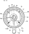
- a Bourdon tube mechanism 57 is supported in a case body 51, and a rotation shaft extending from the Bourdon tube mechanism 57 is inserted into a scale plate 56 to mount an indicator 55. Accordingly, the indicator 55 is rotated relative to scale increments 56a of the scale plate 56 by action of the Bourdon tube mechanism 57 and indicates a pressure.
- a transparent cover plate 53 for protecting the scale plate 56 is provided, and is supported by the case body 51 as a result of a cover 52 being engaged by a thread with the case body 51 with a facing 54 interposed between.
- a Bourdon tube pressure gauge is used as an example, but the present invention can be applied to any type of instrument that has an indicator.
- the scale increments 56a of the scale plate 56 are arranged in an arc shape around the center axis of the indicator 55.
- the tip of the indicator 55 rotates from a scale increment of 0 to 1.5, due to pressure applied from below to the Bourdon tube mechanism 57, to indicate a pressure.
- instrument information the name of the manufacturer, the kind of the instrument such as, for example, pressure gauge or flowmeter, the performance (heat resisting, anti-shock, or the like) and accuracy class of the instrument, and use condition (use no oil, use no water, main part SUS, or the like) are indicated near the center of the scale plate 56. Further, the emblem of the company or the like is indicated therebelow.
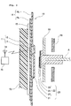
- the IC tag unit 10 for an instrument has an IC tag 11 provided between a first sheet 14a and a second sheet 14b, and the first sheet 14a and the second sheet 14b are adhered to each other by thermocompression bonding or in an unheated manner, whereby the IC tag 11 is held in a waterproof state by the sheet 14.
- an attachment layer 15, formed from an adhesive, for attachment to the transparent cover plate 53 is provided on the front face of the first sheet 14a.
- Both the first sheet 14a and the second sheet 14b are formed from a deformable synthetic resin. Alternatively, for one or both thereof, a glass or hard synthetic resin sheet may be used. In the present embodiment, for the sheet 14, a transparent synthetic resin sheet is used so as not to impair the visibility of the scale plate 56.
- the attachment layer 15 is similarly transparent.
- the first sheet 14a and the second sheet 14b, and the attachment layer 15 have circular shapes having the same diameter, and the diameter is smaller than the inner diameter of the cover 52. However, the diameter may be close to the inner diameter or may be slightly smaller than the inner diameter.
- the IC tag 11 includes an IC chip 12 and an antenna 13 each of which is attached to the first sheet 14a.
- the IC chip 12 is provided near the center of the indicator 55, and the antenna 13 is provided on the IC chip.
- an RFID provided with a power module 31 which transmits and receives a radio wave having RF (Radio Frequency), thus drives the IC chip 12 by electromotive force of electromagnetic wave, and communicates with a memory of the IC chip 12 by a radio wave, is used.
- RF Radio Frequency
- information is stored such as an inspection state before attachment to the instrument or an inspection state at the time of an inspection, a unique ID number of the instrument 50, the model of the instrument 50, calibration time limit of the instrument 50, date of previous inspection of the instrument 50, scheduled date of the next inspection, the name of an inspection operator, and time stamp.
- the antenna 13 is formed on the IC chip 12 by etching of a metal, or the like in this example. However, the antenna 13 may also be formed by printing or vapor deposition on the sheet 14. Further, by an "application and crystallization method" in which: a coating-type organic semiconductor “alkyl DNBDT" is used; and when application onto the sheet 14 is performed, crystallization simultaneously occurs to form a film, an RFID logic circuit may be produced with use of only an organic TFT rectifier, and may be used as the IC tag 11.
- the antenna 13 may be formed as a laminate of a metal foil or resin and a metal foil or etching so as to have such an arc shape that surrounds the scale plate 56, and the antenna 13 may be attached to the facing 54.
- the facing 54 is made of resin, magnetic influence from the case body 51 and the cover 52 can be prevented, and in addition, since the dimensions are large, an RF wave having a long wavelength and large feeding energy can be received.
- the IC chip 11 and the antenna 13' are connected by means of an extraction portion 13a' and an attachable/detachable connector 13b'.
- thermoplastic resin layer may be any thermoplastic resin layer that is melted by heat to fuse laminates to each other, and thus allows the RFID tag to be accommodated.
- thermoplastic resin layer for example, one, or two or more selected from a low-density polyethylene, a medium-density polyethylene, a high-density polyethylene, a linear (flocculent) low-density polyethylene, an ethylene- ⁇ -olefin copolymer obtained by polymerization using a metallocene catalyst (single site catalyst), a polypropylene, an ethylenevinyl acetate copolymer, an ionomer resin, an ethylene-ethyl acrylate copolymer, an ethylene-acrylic acid copolymer, an ethylene-methacrylic acid copolymer, an ethylene-propylene copolymer, a methylpentene polymer, an acid-modified polyolefin resin obtained by modifying a polyolefin resin such as a polyethylene or polypropylene with an unsaturated carboxylic acid such as acrylic acid, methacrylic acid, maleic anhydride, or fuma
- the transparent cover plate 53 and a member 23 not only the material of the sheet 14 formed so as to be hard as described above but also an acrylic plate, a polycarbonate plate, a glass plate, or the like can be used.
- an acrylic adhesive can be used, or an adhesive containing an acrylic polymer and a crosslinking agent may be used.
- the sheet 14 is attached to the transparent cover plate 53 by the attachment layer 15, whereby strength of the transparent cover plate 53 is enhanced and crack or scattering is prevented.
- a scale increment reading module 20 includes a proximity sensor 21 provided on the sheet 14, and a conductive target 22 provided near the center axis of the indicator 55.
- a proximity sensor 21 provided on the sheet 14, and a conductive target 22 provided near the center axis of the indicator 55.
- an induction type proximity sensor which is a proximity sensor capable of detecting movement of an indicator in a contactless manner, is used.
- a capacitance type proximity sensor maybe used, an optical proximity sensor maybe used, or another sensor such as a magnetic sensor obtained by attaching a magnet to an indicator to perform detection may be used.
- a conductive pattern 24 in a spiral shape is formed on a sheet 23 by etching, printing, or the like, and is attached near the center of the indicator 55 through an attachment layer 25 formed from an adhesive material or the like.
- the proximity sensor 21 has a detection coil 21a. The thickness of the spiral located close to the detection coil 21a changes due to rotation of the indicator 55, and the proportion between the conductive layer and the insulation layer changes. Accordingly, the rotation of the conductive target, i.e., the rotation angle of the indicator 55 can be detected.
- the conductive target 22 is used so as to enable detection even when the indicator is made of resin.
- the indicator 55 may be directly detected by the proximity sensor without using the conductive target 22.
- the proximity sensor for example, one of LDC 1000 series of Texas Instruments Inc. can be used.
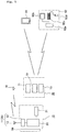
- a long range communication unit 70 is fixed to the rear face of the instrument 50 and used as a wireless communication device.
- the long range communication unit 70 includes: a short range communication module 71 which performs short range communication with the IC tag unit 10 described above; a long range communication module 72 which performs long range communication in accordance with a specification such as 3G or wifi (registered trade mark); a battery 73 for driving these; and an antenna 74 used for each of short range communication and long range communication.
- the long range communication module 72 can be operated by a mobile terminal having a UIF such as a smartphone 91, or a personal computer 92.
- the personal computer includes: a body 92a having a CPU, a memory, and a bus; a display 92b; a keyboard 92c; a mouse 92d; and the like.
- a communication method such as RFID, BLE (Bluetooth Low Energy (Bluetooth is a registered trade mark)), or the like that is operable at weak power can be used.
- Induction current is supplied by the short range communication module 71, whereby power can be supplied via the power module 31 to the RFID and the proximity sensor 21, and the pressure value can be read even in a state where the indicator cannot be seen, such as when the glass is dirty.
- the threshold for monitoring the pressure can be changed and error processing can be changed, by the smartphone 91 or the PC 92 (hereinafter, the smartphone 91 or the like).
- the proximity sensor 21 includes an A/D conversion unit in addition to the detection coil 21a.
- the rotation angle (i.e., pressure value) of the indicator 55 as an analog value read by the detection coil 21a is converted into a digital value by the A/D conversion unit, and the obtained digital value is transmitted to the short range communication module 71 through low-power-consumption short range wireless communication by the IC tag unit 10. Further, data is periodically transmitted by the long range communication unit 70 to the smartphone 91 and the personal computer 92 at remote places.
- the IC tag unit 10 for an instrument is described.
- the release paper for protecting the attachment layer 15 is separated, the cover 52 and the transparent cover plate 53 are removed, and the center of the sheet 14 and the center of the transparent cover plate 53 are aligned with each other as accurately as possible, and the IC tag unit 10 is attached to the reverse surface of the transparent cover plate 53 by the attachment layer 15.
- a pressure gauge such that any user can easily attach the IC tag unit 10 for an instrument on the user end.
- the values obtained in this calibration are stored in a memory of the IC tag of the IC tag sensor unit together with the date and time of the calibration performed. Further, settings such as an interval at which data of the sensor is transmitted, clock adjustment, and a pressure value for which an alert mail is issued, are performed via the mobile terminal and the long range communication unit.
- a second embodiment shown in FIG. 6 is different in that power supply and communication with respect to the IC tag unit 10 are performed by use of a reader writer 80, instead of the long range communication unit 70.
- the reader writer 80 includes a transmission/reception unit 81, a control device 82, a touch panel 83, and an antenna 84, and can perform operation described above with respect to the IC tag unit 10 via the touch panel 83. Further, also during maintenance of the long range communication unit 70 or power failure, reading and the like of the indicator can be performed by use of the reader writer 80.
- the long range communication unit 70 is fixed on the instrument 50 by means of a plate spring 76 having an open lower end 76a.
- This unit 70 includes the short range communication module 71, the long range communication module 72, and the battery 73 as in the embodiment described above, but further, includes a solar battery 75, and generated power therein is charged into the battery 73 to be used.
- a fourth embodiment shown in FIGS. 8A to 8C calibration regarding the zero point and the maximum point is performed without moving the indicator 55.
- the IC tag unit 10 is formed so as to have a larger diameter than in the embodiments described above, and the outer periphery of the IC tag unit 10 is located near the scale increments 56a of the instrument 50. Further, a first pointer 19a and a second pointer 19b are provided so as to be respectively located at the zero point and the maximum point of the scale increments 56a.
- the IC tag unit 10 is rotated in the direction of an arrow R1 together with the transparent cover plate 53 until the first pointer 19a and the indicating portion 55a are overlapped with each other. In this state, the zero point calibration described above is performed.
- the IC tag unit 10 is rotated in the direction of an arrow R2 together with the transparent cover plate 53 until the second pointer 19b and the indicating portion 55a are overlapped with each other. In this state, the maximum point calibration described above is performed. Then, the IC tag unit 10 is rotated until the state shown in FIG. 8A is realized, and the calibration ends.
- the facing 54 and the antenna 13' may be simultaneously rotated, but may be rotated with the connector 13b' of the antenna 13' removed.
- the conductive target 22 described above may be provided with a projection similar to the indicating portion 55a.
- the above calibration can be performed by rotating the conductive target 22 to a position where the projection is overlapped with the indicating portion 55a.
- the present invention when mounted to an existing instrument, can be used as a support device for checking calibration of the instrument and for performing periodic inspection of the instrument.
- the present invention can be used for existing instruments, for example, industrial instruments such as pressure gauges, thermometers, flowmeters, and power meters.
Landscapes
- Physics & Mathematics (AREA)
- General Physics & Mathematics (AREA)
- Engineering & Computer Science (AREA)
- Computer Networks & Wireless Communication (AREA)
- Arrangements For Transmission Of Measured Signals (AREA)
- Testing Or Calibration Of Command Recording Devices (AREA)
- Measuring Fluid Pressure (AREA)
Claims (11)
- Système comprenant une unité d'étiquette à circuit intégré (10) pour un instrument (50) et l'instrument (50),l'unité d'étiquette à circuit intégré (10) étant configurée pour être montée sur ledit instrument (50),l'instrument (50) présentant : une plaque graduée (56), un indicateur (55) et une plaque de couverture transparente (53) qui couvre la plaque graduée (56) et l'indicateur (55), la plaque graduée (56) étant pourvue de graduations (56a),l'unité d'étiquette à circuit intégré (10) comprenant :une étiquette à circuit intégré (11) incluant une puce électronique et une antenne (13), l'étiquette à circuit intégré (11) étant apte à communiquer, par onde radio sans contact, des informations stockées, etun milieu de montage (14) configuré pour monter l'étiquette à circuit intégré (11) sur la plaque de couverture transparente (53) et retenir l'étiquette à circuit intégré (11),l'unité d'étiquette à circuit intégré (10) étant configurée pour être utilisée avec un lecteur sans fil (30) qui effectue des communications sans fil avec l'étiquette à circuit intégré (11), l'étiquette à circuit intégré (11) effectuant des communications sans fil avec le lecteur sans fil (30) via l'antenne (13), etl'étiquette à circuit intégré (11) est prévue sur le milieu de montage (14) dans une position, dans laquelle elle n'est chevauchée, dans une direction de vision, ni par des graduations (56a), ni par une partie d'indication (55a) de l'indicateur (55) à un moment, auquel elle est montée sur la plaque de couverture transparente (53).caractérisé en ce quel'unité d'étiquette à circuit intégré (10) comprend en plus un module de lecture de graduations (20) quilit le fonctionnement de l'indicateur (55) et quiinclut un capteur (21) qui est opposé à l'indicateur (55) sur le milieu de montage (14) et lit une position de l'indicateur (55) sur la base d'un déplacement relatif de celui-ci.
- Système suivant la revendication 1, dans lequel
le lecteur sans fil (30) inclut un module (71) pour une communication sans fil à courte portée à effectuer avec l'étiquette à circuit intégré (11), ainsi qu'un module (72) pour une communication sans fil à longue portée. - Système suivant la revendication 1, dans lequel
le milieu de montage (14) retient le capteur (21) de sorte que celui-ci se situe à proximité d'un axe central de l'indicateur (55), et un marqueur, qui spécifie un angle sur la base d'une rotation de ce dernier par rapport au capteur (21), est monté à proximité de l'axe central de l'indicateur (55). - Système suivant la revendication 3, dans lequel
le milieu de montage (14) présente un premier pointeur (19a) et un second pointer (19b) qui indique des positions d'une valeur minimale et d'une valeur maximale de l'indicateur (55) et chacun des pointeurs (19a, 19b) peut être aligné sur l'indicateur (55) par rotation du milieu de montage (14) par rapport au marqueur fixé sur l'indicateur (55). - Système suivant la revendication 1 ou 2, dans lequel
l'instrument (50) inclut un parement (54) et l'antenne (13) est prévue le long du parement (54) de sorte entourer la plaque graduée (56). - Un autre système d'étiquette à circuit intégré comprenant :le système et le lecteur sans fil (30) suivant la revendication 1, dans lequelle lecteur sans fil (30) présente une source d'alimentation, à partir de laquelle est obtenue une puissance à fournir au module d'alimentation (31) de l'étiquette à circuit intégré (11).
- L'autre système suivant la revendication 6, dans lequel
le lecteur sans fil (30) inclut une pile (73) comme source d'alimentation. - L'autre système suivant la revendication 6, dans lequel
le lecteur sans fil (30) inclut une pile solaire (75) comme source d'alimentation. - L'autre système suivant la revendication 6, dans lequel
le lecteur sans fil (30) est un lecteur scripteur (80). - Système suivant la revendication 1, dans lequel
le milieu de montage (14) retient le capteur (21) de sorte que celui-ci se situe à proximité d'un axe central de l'indicateur (55) et un marqueur, qui spécifie un angle sur la base de rotation de ce dernier par rapport au capteur (21), est monté à proximité de l'axe central de l'indicateur (55). - Procédé à exécuter au moyen du système suivant la revendication 4, le procédé comprenant l'étalonnage de l'instrument (50), le procédé comprenant les étapes suivantes qui consistent à :effectuer un étalonnage du point zéro en faisant tourner l'unité d'étiquette à circuit intégré (10) avec la plaque de couverture transparente (53) de sorte que le premier pointeur (19a) est chevauché par une partie d'indication (55a) de l'indicateur (55),effectuer un étalonnage du point maximal en faisant tourner l'unité d'étiquette à circuit intégré (10) avec la plaque de couverture transparente (53) de sorte que le second pointeur (19b) est chevauché par la partie d'indication (55a), etfaire tourner l'unité d'étiquette à circuit intégré (10) avec la plaque de couverture transparente (53) jusqu'à ce que le premier pointeur (19a) et le second pointeur (19b) soient chevauchés par des parties correspondantes des graduations (56a) de la plaque graduée (56).
Applications Claiming Priority (1)
| Application Number | Priority Date | Filing Date | Title |
|---|---|---|---|
| PCT/JP2016/063758 WO2017195251A1 (fr) | 2016-05-09 | 2016-05-09 | Unité d'étiquette à circuit intégré pour instrument, système d'étiquette à circuit intégré pour instrument, instrument comportant une unité d'étiquette à circuit intégré, et procédé d'étalonnage d'instrument comportant une unité d'étiquette à circuit intégré |
Publications (3)
| Publication Number | Publication Date |
|---|---|
| EP3457377A1 EP3457377A1 (fr) | 2019-03-20 |
| EP3457377A4 EP3457377A4 (fr) | 2019-05-01 |
| EP3457377B1 true EP3457377B1 (fr) | 2020-07-29 |
Family
ID=59081997
Family Applications (1)
| Application Number | Title | Priority Date | Filing Date |
|---|---|---|---|
| EP16901600.3A Active EP3457377B1 (fr) | 2016-05-09 | 2016-05-09 | Unité d'étiquette à circuit intégré pour instrument, système d'étiquette à circuit intégré pour instrument, instrument comportant une unité d'étiquette à circuit intégré, et procédé d'étalonnage d'instrument comportant une unité d'étiquette à circuit intégré |
Country Status (6)
| Country | Link |
|---|---|
| US (1) | US11015963B2 (fr) |
| EP (1) | EP3457377B1 (fr) |
| JP (1) | JP6150319B1 (fr) |
| CN (1) | CN109074724B (fr) |
| SG (1) | SG11201809924QA (fr) |
| WO (1) | WO2017195251A1 (fr) |
Families Citing this family (7)
| Publication number | Priority date | Publication date | Assignee | Title |
|---|---|---|---|---|
| JP6840644B2 (ja) * | 2017-09-05 | 2021-03-10 | 株式会社東芝 | 半導体装置 |
| EP3865071B1 (fr) * | 2018-10-11 | 2022-09-21 | FUJIFILM Corporation | Sonde ultrasonore |
| CN109238341B (zh) * | 2018-11-12 | 2020-06-23 | 安徽江淮汽车集团股份有限公司 | 一种仪表自动化指针校零方法 |
| US11780594B2 (en) * | 2019-10-02 | 2023-10-10 | Ppg Industries Ohio, Inc. | Transparency including a wireless sensor |
| JP7050039B2 (ja) | 2019-10-31 | 2022-04-07 | 長野計器株式会社 | 圧力計 |
| CN112949330B (zh) * | 2021-02-04 | 2021-09-17 | 温州格洛博电子有限公司 | 一种多射频应答器环布式无源计量装置及其信息采集方法 |
| CN120958297A (zh) * | 2023-04-18 | 2025-11-14 | 星电株式会社 | 传感器装置系统 |
Family Cites Families (21)
| Publication number | Priority date | Publication date | Assignee | Title |
|---|---|---|---|---|
| US6742396B2 (en) * | 2001-04-07 | 2004-06-01 | Robertshaw Controls Company | Method for upgrading a dial indicator to provide remote indication capability |
| JP4129369B2 (ja) * | 2002-04-30 | 2008-08-06 | 株式会社エリート | Rfidタグを利用した流量計の検針方法及び検針システム |
| JP3551962B2 (ja) * | 2002-09-13 | 2004-08-11 | オムロン株式会社 | 無線icタグ読取装置とそのシステム |
| JP2005316681A (ja) | 2004-04-28 | 2005-11-10 | Tokyo Electric Power Co Inc:The | 電力量検針支援装置、端末装置、電力量検針支援方法 |
| EP1760900B1 (fr) * | 2004-06-10 | 2011-04-06 | Panasonic Corporation | Etiquette radio et procede de modification de distance de communication d"etiquette radio |
| CN2781340Y (zh) * | 2005-06-17 | 2006-05-17 | 张华� | 主动式无线温度传感器 |
| US8212655B2 (en) | 2006-03-30 | 2012-07-03 | Rosemount Inc. | System and method for identification of process components |
| JP2007298411A (ja) * | 2006-04-28 | 2007-11-15 | Toshiba Corp | 計量器 |
| TWM300807U (en) * | 2006-06-07 | 2006-11-11 | Li-Jen Chen | Adjustable structure of sensory device for pressure meter |
| DE102009000692A1 (de) * | 2009-02-06 | 2010-08-12 | Wika Alexander Wiegand Gmbh & Co. Kg | Messgerät |
| JP5358332B2 (ja) * | 2009-07-23 | 2013-12-04 | テルモ株式会社 | 体温測定システム及びデータ読み取り装置ならびにその駆動制御方法 |
| US9377284B2 (en) * | 2010-04-30 | 2016-06-28 | Renishaw Plc | Metrology apparatus |
| JP3161399U (ja) * | 2010-05-18 | 2010-07-29 | 長野計器株式会社 | 指針読取装置 |
| US20150022010A1 (en) * | 2013-05-10 | 2015-01-22 | DvineWave Inc. | Wireless charging and powering of electronic sensors in a vehicle |
| CN203024803U (zh) * | 2013-01-18 | 2013-06-26 | 重庆中陆承大科技有限公司 | 一种水表以及水表识别系统 |
| US11262215B2 (en) * | 2013-09-17 | 2022-03-01 | Sensia Llc | Smart measurement system |
| JP5896502B1 (ja) | 2014-05-12 | 2016-03-30 | 株式会社木幡計器製作所 | 計器用icタグユニット及びicタグ付き計器 |
| CN204085611U (zh) * | 2014-08-08 | 2015-01-07 | 重庆中陆承大科技有限公司 | 带电子标签的水表部件 |
| US9677919B2 (en) * | 2014-11-26 | 2017-06-13 | Rosemount Inc. | Gauge display system |
| CN204463144U (zh) * | 2015-01-19 | 2015-07-08 | 国网宁夏电力公司电力科学研究院 | 一种rfid系统及内置式rfid防窃电低压ct |
| CN205003707U (zh) * | 2015-09-10 | 2016-01-27 | 北京国金源富科技有限公司 | 电子标签和应用该电子标签的电能表 |
-
2016
- 2016-05-09 EP EP16901600.3A patent/EP3457377B1/fr active Active
- 2016-05-09 JP JP2017510414A patent/JP6150319B1/ja active Active
- 2016-05-09 SG SG11201809924QA patent/SG11201809924QA/en unknown
- 2016-05-09 CN CN201680085379.8A patent/CN109074724B/zh active Active
- 2016-05-09 US US16/300,007 patent/US11015963B2/en active Active
- 2016-05-09 WO PCT/JP2016/063758 patent/WO2017195251A1/fr not_active Ceased
Non-Patent Citations (1)
| Title |
|---|
| None * |
Also Published As
| Publication number | Publication date |
|---|---|
| US20190145802A1 (en) | 2019-05-16 |
| CN109074724B (zh) | 2020-11-06 |
| JPWO2017195251A1 (ja) | 2018-05-31 |
| EP3457377A4 (fr) | 2019-05-01 |
| WO2017195251A1 (fr) | 2017-11-16 |
| EP3457377A1 (fr) | 2019-03-20 |
| JP6150319B1 (ja) | 2017-06-21 |
| US11015963B2 (en) | 2021-05-25 |
| SG11201809924QA (en) | 2018-12-28 |
| CN109074724A (zh) | 2018-12-21 |
Similar Documents
| Publication | Publication Date | Title |
|---|---|---|
| EP3457377B1 (fr) | Unité d'étiquette à circuit intégré pour instrument, système d'étiquette à circuit intégré pour instrument, instrument comportant une unité d'étiquette à circuit intégré, et procédé d'étalonnage d'instrument comportant une unité d'étiquette à circuit intégré | |
| EP3144642B1 (fr) | Unité d'étiquette à circuit intégré pour instrument, et instrument comprenant l'étiquette à circuit intégré | |
| JP5443522B2 (ja) | 離間距離導出システムおよびシクネスゲージ | |
| CN109074731B (zh) | 磁性标识器及驾驶支援系统 | |
| JP6313883B2 (ja) | 計器用icタグユニット、計器用icタグシステム、icタグユニットを備えた計器及びicタグユニットを備えた計器の校正方法 | |
| US20130305551A1 (en) | Dimensioning accessory for mobile device | |
| JP2016051438A (ja) | 容器、液量管理システム及び液量管理方法 | |
| KR20190036756A (ko) | 운송 데이터 로깅 장치 및 이를 포함하는 물품 운송 시스템 | |
| JP2017203775A5 (fr) | ||
| US20210072044A1 (en) | Output system and gauge | |
| CN104504435A (zh) | 一种应用于人体体表的体温检测射频标签 | |
| CN204463185U (zh) | 一种应用于人体体表的体温检测射频标签 | |
| JP6709893B2 (ja) | 計器指針値出力用磁気センサ装置、これを備えた計器、及び、そのキャリブレーション方法 | |
| JP5921728B2 (ja) | Rfidラベルによるトリガイベントの形成 | |
| TW200424545A (en) | Azimuth measuring method and apparatus, and recording medium having stored the azimuth measuring method | |
| CN101685293B (zh) | 多功能时间显示装置 | |
| JP4520759B2 (ja) | メータ装置およびそれを用いたメータ管理システム | |
| JP2010039691A (ja) | Rfidタグ読み取り装置およびrfid管理システム | |
| JP2024035627A (ja) | タグ、通信システム及び製造方法 | |
| KR20100089209A (ko) | 알에프아이디 장치 | |
| TWM448741U (zh) | 具光導引之讀卡裝置 | |
| KR20100089203A (ko) | 금속재질에 사용 가능한 알에프아이디 장치 |
Legal Events
| Date | Code | Title | Description |
|---|---|---|---|
| STAA | Information on the status of an ep patent application or granted ep patent |
Free format text: STATUS: THE INTERNATIONAL PUBLICATION HAS BEEN MADE |
|
| PUAI | Public reference made under article 153(3) epc to a published international application that has entered the european phase |
Free format text: ORIGINAL CODE: 0009012 |
|
| STAA | Information on the status of an ep patent application or granted ep patent |
Free format text: STATUS: REQUEST FOR EXAMINATION WAS MADE |
|
| 17P | Request for examination filed |
Effective date: 20181205 |
|
| AK | Designated contracting states |
Kind code of ref document: A1 Designated state(s): AL AT BE BG CH CY CZ DE DK EE ES FI FR GB GR HR HU IE IS IT LI LT LU LV MC MK MT NL NO PL PT RO RS SE SI SK SM TR |
|
| AX | Request for extension of the european patent |
Extension state: BA ME |
|
| A4 | Supplementary search report drawn up and despatched |
Effective date: 20190403 |
|
| RIC1 | Information provided on ipc code assigned before grant |
Ipc: G08C 17/02 20060101AFI20190328BHEP Ipc: G01D 18/00 20060101ALI20190328BHEP Ipc: G01D 11/26 20060101ALI20190328BHEP |
|
| DAV | Request for validation of the european patent (deleted) | ||
| DAX | Request for extension of the european patent (deleted) | ||
| STAA | Information on the status of an ep patent application or granted ep patent |
Free format text: STATUS: EXAMINATION IS IN PROGRESS |
|
| 17Q | First examination report despatched |
Effective date: 20190920 |
|
| GRAP | Despatch of communication of intention to grant a patent |
Free format text: ORIGINAL CODE: EPIDOSNIGR1 |
|
| STAA | Information on the status of an ep patent application or granted ep patent |
Free format text: STATUS: GRANT OF PATENT IS INTENDED |
|
| INTG | Intention to grant announced |
Effective date: 20200428 |
|
| GRAS | Grant fee paid |
Free format text: ORIGINAL CODE: EPIDOSNIGR3 |
|
| GRAA | (expected) grant |
Free format text: ORIGINAL CODE: 0009210 |
|
| STAA | Information on the status of an ep patent application or granted ep patent |
Free format text: STATUS: THE PATENT HAS BEEN GRANTED |
|
| AK | Designated contracting states |
Kind code of ref document: B1 Designated state(s): AL AT BE BG CH CY CZ DE DK EE ES FI FR GB GR HR HU IE IS IT LI LT LU LV MC MK MT NL NO PL PT RO RS SE SI SK SM TR |
|
| REG | Reference to a national code |
Ref country code: CH Ref legal event code: EP |
|
| REG | Reference to a national code |
Ref country code: AT Ref legal event code: REF Ref document number: 1296707 Country of ref document: AT Kind code of ref document: T Effective date: 20200815 |
|
| REG | Reference to a national code |
Ref country code: IE Ref legal event code: FG4D |
|
| REG | Reference to a national code |
Ref country code: DE Ref legal event code: R096 Ref document number: 602016041115 Country of ref document: DE |
|
| REG | Reference to a national code |
Ref country code: LT Ref legal event code: MG4D |
|
| REG | Reference to a national code |
Ref country code: NL Ref legal event code: MP Effective date: 20200729 |
|
| REG | Reference to a national code |
Ref country code: AT Ref legal event code: MK05 Ref document number: 1296707 Country of ref document: AT Kind code of ref document: T Effective date: 20200729 |
|
| PG25 | Lapsed in a contracting state [announced via postgrant information from national office to epo] |
Ref country code: ES Free format text: LAPSE BECAUSE OF FAILURE TO SUBMIT A TRANSLATION OF THE DESCRIPTION OR TO PAY THE FEE WITHIN THE PRESCRIBED TIME-LIMIT Effective date: 20200729 Ref country code: BG Free format text: LAPSE BECAUSE OF FAILURE TO SUBMIT A TRANSLATION OF THE DESCRIPTION OR TO PAY THE FEE WITHIN THE PRESCRIBED TIME-LIMIT Effective date: 20201029 Ref country code: PT Free format text: LAPSE BECAUSE OF FAILURE TO SUBMIT A TRANSLATION OF THE DESCRIPTION OR TO PAY THE FEE WITHIN THE PRESCRIBED TIME-LIMIT Effective date: 20201130 Ref country code: SE Free format text: LAPSE BECAUSE OF FAILURE TO SUBMIT A TRANSLATION OF THE DESCRIPTION OR TO PAY THE FEE WITHIN THE PRESCRIBED TIME-LIMIT Effective date: 20200729 Ref country code: HR Free format text: LAPSE BECAUSE OF FAILURE TO SUBMIT A TRANSLATION OF THE DESCRIPTION OR TO PAY THE FEE WITHIN THE PRESCRIBED TIME-LIMIT Effective date: 20200729 Ref country code: GR Free format text: LAPSE BECAUSE OF FAILURE TO SUBMIT A TRANSLATION OF THE DESCRIPTION OR TO PAY THE FEE WITHIN THE PRESCRIBED TIME-LIMIT Effective date: 20201030 Ref country code: LT Free format text: LAPSE BECAUSE OF FAILURE TO SUBMIT A TRANSLATION OF THE DESCRIPTION OR TO PAY THE FEE WITHIN THE PRESCRIBED TIME-LIMIT Effective date: 20200729 Ref country code: FI Free format text: LAPSE BECAUSE OF FAILURE TO SUBMIT A TRANSLATION OF THE DESCRIPTION OR TO PAY THE FEE WITHIN THE PRESCRIBED TIME-LIMIT Effective date: 20200729 Ref country code: AT Free format text: LAPSE BECAUSE OF FAILURE TO SUBMIT A TRANSLATION OF THE DESCRIPTION OR TO PAY THE FEE WITHIN THE PRESCRIBED TIME-LIMIT Effective date: 20200729 Ref country code: NO Free format text: LAPSE BECAUSE OF FAILURE TO SUBMIT A TRANSLATION OF THE DESCRIPTION OR TO PAY THE FEE WITHIN THE PRESCRIBED TIME-LIMIT Effective date: 20201029 |
|
| PG25 | Lapsed in a contracting state [announced via postgrant information from national office to epo] |
Ref country code: PL Free format text: LAPSE BECAUSE OF FAILURE TO SUBMIT A TRANSLATION OF THE DESCRIPTION OR TO PAY THE FEE WITHIN THE PRESCRIBED TIME-LIMIT Effective date: 20200729 Ref country code: RS Free format text: LAPSE BECAUSE OF FAILURE TO SUBMIT A TRANSLATION OF THE DESCRIPTION OR TO PAY THE FEE WITHIN THE PRESCRIBED TIME-LIMIT Effective date: 20200729 Ref country code: LV Free format text: LAPSE BECAUSE OF FAILURE TO SUBMIT A TRANSLATION OF THE DESCRIPTION OR TO PAY THE FEE WITHIN THE PRESCRIBED TIME-LIMIT Effective date: 20200729 Ref country code: IS Free format text: LAPSE BECAUSE OF FAILURE TO SUBMIT A TRANSLATION OF THE DESCRIPTION OR TO PAY THE FEE WITHIN THE PRESCRIBED TIME-LIMIT Effective date: 20201129 |
|
| PG25 | Lapsed in a contracting state [announced via postgrant information from national office to epo] |
Ref country code: NL Free format text: LAPSE BECAUSE OF FAILURE TO SUBMIT A TRANSLATION OF THE DESCRIPTION OR TO PAY THE FEE WITHIN THE PRESCRIBED TIME-LIMIT Effective date: 20200729 |
|
| PG25 | Lapsed in a contracting state [announced via postgrant information from national office to epo] |
Ref country code: RO Free format text: LAPSE BECAUSE OF FAILURE TO SUBMIT A TRANSLATION OF THE DESCRIPTION OR TO PAY THE FEE WITHIN THE PRESCRIBED TIME-LIMIT Effective date: 20200729 Ref country code: DK Free format text: LAPSE BECAUSE OF FAILURE TO SUBMIT A TRANSLATION OF THE DESCRIPTION OR TO PAY THE FEE WITHIN THE PRESCRIBED TIME-LIMIT Effective date: 20200729 Ref country code: CZ Free format text: LAPSE BECAUSE OF FAILURE TO SUBMIT A TRANSLATION OF THE DESCRIPTION OR TO PAY THE FEE WITHIN THE PRESCRIBED TIME-LIMIT Effective date: 20200729 Ref country code: IT Free format text: LAPSE BECAUSE OF FAILURE TO SUBMIT A TRANSLATION OF THE DESCRIPTION OR TO PAY THE FEE WITHIN THE PRESCRIBED TIME-LIMIT Effective date: 20200729 Ref country code: EE Free format text: LAPSE BECAUSE OF FAILURE TO SUBMIT A TRANSLATION OF THE DESCRIPTION OR TO PAY THE FEE WITHIN THE PRESCRIBED TIME-LIMIT Effective date: 20200729 Ref country code: SM Free format text: LAPSE BECAUSE OF FAILURE TO SUBMIT A TRANSLATION OF THE DESCRIPTION OR TO PAY THE FEE WITHIN THE PRESCRIBED TIME-LIMIT Effective date: 20200729 |
|
| REG | Reference to a national code |
Ref country code: DE Ref legal event code: R097 Ref document number: 602016041115 Country of ref document: DE |
|
| PG25 | Lapsed in a contracting state [announced via postgrant information from national office to epo] |
Ref country code: AL Free format text: LAPSE BECAUSE OF FAILURE TO SUBMIT A TRANSLATION OF THE DESCRIPTION OR TO PAY THE FEE WITHIN THE PRESCRIBED TIME-LIMIT Effective date: 20200729 |
|
| PLBE | No opposition filed within time limit |
Free format text: ORIGINAL CODE: 0009261 |
|
| STAA | Information on the status of an ep patent application or granted ep patent |
Free format text: STATUS: NO OPPOSITION FILED WITHIN TIME LIMIT |
|
| PG25 | Lapsed in a contracting state [announced via postgrant information from national office to epo] |
Ref country code: SK Free format text: LAPSE BECAUSE OF FAILURE TO SUBMIT A TRANSLATION OF THE DESCRIPTION OR TO PAY THE FEE WITHIN THE PRESCRIBED TIME-LIMIT Effective date: 20200729 |
|
| 26N | No opposition filed |
Effective date: 20210430 |
|
| PG25 | Lapsed in a contracting state [announced via postgrant information from national office to epo] |
Ref country code: SI Free format text: LAPSE BECAUSE OF FAILURE TO SUBMIT A TRANSLATION OF THE DESCRIPTION OR TO PAY THE FEE WITHIN THE PRESCRIBED TIME-LIMIT Effective date: 20200729 |
|
| REG | Reference to a national code |
Ref country code: CH Ref legal event code: PL |
|
| PG25 | Lapsed in a contracting state [announced via postgrant information from national office to epo] |
Ref country code: CH Free format text: LAPSE BECAUSE OF NON-PAYMENT OF DUE FEES Effective date: 20210531 Ref country code: LU Free format text: LAPSE BECAUSE OF NON-PAYMENT OF DUE FEES Effective date: 20210509 Ref country code: MC Free format text: LAPSE BECAUSE OF FAILURE TO SUBMIT A TRANSLATION OF THE DESCRIPTION OR TO PAY THE FEE WITHIN THE PRESCRIBED TIME-LIMIT Effective date: 20200729 Ref country code: LI Free format text: LAPSE BECAUSE OF NON-PAYMENT OF DUE FEES Effective date: 20210531 |
|
| REG | Reference to a national code |
Ref country code: BE Ref legal event code: MM Effective date: 20210531 |
|
| PG25 | Lapsed in a contracting state [announced via postgrant information from national office to epo] |
Ref country code: IE Free format text: LAPSE BECAUSE OF NON-PAYMENT OF DUE FEES Effective date: 20210509 |
|
| PG25 | Lapsed in a contracting state [announced via postgrant information from national office to epo] |
Ref country code: BE Free format text: LAPSE BECAUSE OF NON-PAYMENT OF DUE FEES Effective date: 20210531 |
|
| PG25 | Lapsed in a contracting state [announced via postgrant information from national office to epo] |
Ref country code: CY Free format text: LAPSE BECAUSE OF FAILURE TO SUBMIT A TRANSLATION OF THE DESCRIPTION OR TO PAY THE FEE WITHIN THE PRESCRIBED TIME-LIMIT Effective date: 20200729 |
|
| PG25 | Lapsed in a contracting state [announced via postgrant information from national office to epo] |
Ref country code: HU Free format text: LAPSE BECAUSE OF FAILURE TO SUBMIT A TRANSLATION OF THE DESCRIPTION OR TO PAY THE FEE WITHIN THE PRESCRIBED TIME-LIMIT; INVALID AB INITIO Effective date: 20160509 |
|
| REG | Reference to a national code |
Ref country code: DE Ref legal event code: R082 Ref document number: 602016041115 Country of ref document: DE Representative=s name: PUSCHMANN BORCHERT KAISER KLETTNER PATENTANWAE, DE Ref country code: DE Ref legal event code: R082 Ref document number: 602016041115 Country of ref document: DE Representative=s name: PATCARE PATENTANWAELTE PARTNERSCHAFT MBB, DE |
|
| PG25 | Lapsed in a contracting state [announced via postgrant information from national office to epo] |
Ref country code: MK Free format text: LAPSE BECAUSE OF FAILURE TO SUBMIT A TRANSLATION OF THE DESCRIPTION OR TO PAY THE FEE WITHIN THE PRESCRIBED TIME-LIMIT Effective date: 20200729 |
|
| PG25 | Lapsed in a contracting state [announced via postgrant information from national office to epo] |
Ref country code: MT Free format text: LAPSE BECAUSE OF FAILURE TO SUBMIT A TRANSLATION OF THE DESCRIPTION OR TO PAY THE FEE WITHIN THE PRESCRIBED TIME-LIMIT Effective date: 20200729 |
|
| PGFP | Annual fee paid to national office [announced via postgrant information from national office to epo] |
Ref country code: DE Payment date: 20250527 Year of fee payment: 10 |
|
| PGFP | Annual fee paid to national office [announced via postgrant information from national office to epo] |
Ref country code: GB Payment date: 20250522 Year of fee payment: 10 |
|
| PGFP | Annual fee paid to national office [announced via postgrant information from national office to epo] |
Ref country code: FR Payment date: 20250523 Year of fee payment: 10 |
|
| PG25 | Lapsed in a contracting state [announced via postgrant information from national office to epo] |
Ref country code: TR Free format text: LAPSE BECAUSE OF FAILURE TO SUBMIT A TRANSLATION OF THE DESCRIPTION OR TO PAY THE FEE WITHIN THE PRESCRIBED TIME-LIMIT Effective date: 20200729 |