EP3457532B1 - Dauermagnet für eine dauermagnetmaschine - Google Patents
Dauermagnet für eine dauermagnetmaschine Download PDFInfo
- Publication number
- EP3457532B1 EP3457532B1 EP17191422.9A EP17191422A EP3457532B1 EP 3457532 B1 EP3457532 B1 EP 3457532B1 EP 17191422 A EP17191422 A EP 17191422A EP 3457532 B1 EP3457532 B1 EP 3457532B1
- Authority
- EP
- European Patent Office
- Prior art keywords
- slits
- slit
- base body
- permanent magnet
- depth
- Prior art date
- Legal status (The legal status is an assumption and is not a legal conclusion. Google has not performed a legal analysis and makes no representation as to the accuracy of the status listed.)
- Active
Links
Images



Classifications
-
- H—ELECTRICITY
- H02—GENERATION; CONVERSION OR DISTRIBUTION OF ELECTRIC POWER
- H02K—DYNAMO-ELECTRIC MACHINES
- H02K15/00—Processes or apparatus specially adapted for manufacturing, assembling, maintaining or repairing of dynamo-electric machines
- H02K15/02—Processes or apparatus specially adapted for manufacturing, assembling, maintaining or repairing of dynamo-electric machines of stator or rotor bodies
- H02K15/03—Processes or apparatus specially adapted for manufacturing, assembling, maintaining or repairing of dynamo-electric machines of stator or rotor bodies having permanent magnets
-
- H—ELECTRICITY
- H01—ELECTRIC ELEMENTS
- H01F—MAGNETS; INDUCTANCES; TRANSFORMERS; SELECTION OF MATERIALS FOR THEIR MAGNETIC PROPERTIES
- H01F41/00—Apparatus or processes specially adapted for manufacturing or assembling magnets, inductances or transformers; Apparatus or processes specially adapted for manufacturing materials characterised by their magnetic properties
- H01F41/02—Apparatus or processes specially adapted for manufacturing or assembling magnets, inductances or transformers; Apparatus or processes specially adapted for manufacturing materials characterised by their magnetic properties for manufacturing cores, coils, or magnets
- H01F41/0253—Apparatus or processes specially adapted for manufacturing or assembling magnets, inductances or transformers; Apparatus or processes specially adapted for manufacturing materials characterised by their magnetic properties for manufacturing cores, coils, or magnets for manufacturing permanent magnets
-
- H—ELECTRICITY
- H01—ELECTRIC ELEMENTS
- H01F—MAGNETS; INDUCTANCES; TRANSFORMERS; SELECTION OF MATERIALS FOR THEIR MAGNETIC PROPERTIES
- H01F7/00—Magnets
- H01F7/02—Permanent magnets [PM]
- H01F7/0205—Magnetic circuits with PM in general
- H01F7/021—Construction of PM
Definitions
- the present invention relates to the field of reducing eddy current losses in permanent magnets in a permanent magnet machine.
- the present invention relates to a permanent magnet for a permanent magnet machine, it is also called a permanent magnet machine, and a method of manufacturing a permanent magnet for a permanent magnet machine.
- coating the finished current permanent magnet may be difficult as the adhesive property of the surface of the small magnetic pieces and the glue layers are different. This may cause quality problems of the coating.
- Patent documents EP 1 065 777 A1 , US 2006/186752 A1 , JP 2013 219911 A and DE 10 2013 211858 A1 disclose examples of such permanent magnets.
- the manufacturing costs of a permanent magnet are crucial from the economic perspective of the permanent magnet machine. Further, the reliability of the permanent magnet is a key factor for the operational costs of the permanent magnet machine.
- the depth of the first slit and the further first slit is measured between a surface position on the first side where the respective first slit or the further first slit opens to the first side and the bottom of the respective first slit or the further first slit.
- the base body is formed monolithically as a one-piece element of a magnetic material, wherein the permanent magnet is able to reduce magnet eddy current losses.
- the base body is formed such that the base body comprises a first side and a second side, which are interconnected by a third side and a fourth side as well as a fifth side and a sixth side.
- the base body is formed monolithically as a one-piece element of a magnetic material. The first side and the second side are distanced from each other, and delimit the base body in one dimension.
- the slit may be formed in the base body by for example multi wire cutting, laser cutting, plasma cutting or autogenous gas cutting.
- the first slit extends from the first side in the direction of the second side and may be defined such that the first slit is opened to the first side and extends in the direction of the second side without an opening in the second side.
- the first slit may be a blind hole ending inside the base body.
- a method of manufacturing a permanent magnet for a permanent magnet machine comprises providing a base body having a first side and a second side which is the opposite side with respect to the first side, and forming at least one first slit and at least one further slit in the base body, such that the at least one first slit and the at least one further first slit extend from the first side in the direction of the second side.
- At least one further first slit is formed in the base body such that the at least one first slit and the at least one further first slit extend parallel to each other.
- the at least one second slit may be formed by the same method as the at least one first slit.
- the first slit may be a blind hole ending inside the base body.
- each first slit is arranged between two second slits and each second slit is arranged between two first slits.
- the depth when the first slit extends angulated and not perpendicular with respect to the first side, the depth may be defined as a distance between the bottom of the first slit inside the base body and the first side measured perpendicular to the first side. Accordingly, when the second slit extends angulated and not perpendicular to the second side, the depth may be defined as a distance between the bottom of the second slit inside the base body and the second side measured perpendicular to the second side.
- each of the first slits may have a different depth. Furthermore, when there are formed more than one second slit in the base body, each of the second slits may have a different depth.
- the depth of one first slit and the depth of one adjacent second slit may be added to a respective sum which may be compared to the distance between the first side and the second side.
- a first slit and an adjacent second slit may form the sum, even though one of the first slits or one of the second slits is added to two different sums.
- one of the at least one first slit and one of the at least one second slit may form a pair of slits.
- the first slit and the second slit of the pair of slits are distanced from each other in a first direction being parallel to the first side.
- a middle position may be defined as the position which is in the geometrical middle in the first direction between the first slit and the second slit of the pair of slits.
- the distance between the first side and the second side may be measured at the middle position, and is the distance between the first side and the second side in a second direction being perpendicular to the first direction. Therefore, seen in the second direction in a cross section having a normal being parallel to a third direction which is perpendicular to the first direction and the second direction, an extension of the first slit and an extension of the second slit overlap in the second direction.
- the base body is formed such that the at least one first slit and/or the at least one second slit have the same depth in a direction extending from the first side to the second side.
- an extension of the first slit begins on the first side at a surface position where the first slit opens to the first side. At this surface position a tangent is applied on the contour of the curvature of the first side.
- the first slit extends from the first side in the direction of the second side without any curvatures.
- the first slit is a blind hole ending inside the base body and hence comprises a bottom.
- a connection line is defined from the surface position on the first side to the bottom. Between the connection line and the tangent an angle is defined, which is in the range of larger than 0° and smaller than 180°, i.e. 45° to 135°, particularly in the range of 65° to 115°, more particularly 90°.
- an extension of the second slit begins on the second side at a surface position where the second slit opens to the second side. At this surface position a tangent is applied on the contour of the curvature of the second side.
- the second slit extends from the second side in the direction of the first side without any curvatures.
- the second slit is a blind hole ending inside the base body and hence comprises a bottom.
- a connection line is defined from the surface position on the second side to the bottom. Between the connection line and the tangent an angle is defined, which is in the range of larger than 0° and smaller than 180°, i.e. 45° to 135°, particularly in the range of 65° to 115°, more particularly 90°.
- the base body may be formed such that the at least one second slit extends from the second side in the direction of the first side more than at least for example 90% of a distance between the second side and the first side.
- the 10% of the material which is not cut by the first slit may be cut instead by the second slit and at the same time due to the second slit being distanced to the first slit in the direction which is perpendicular to the first side, the base body is still be held together without the need of additional glue.
- the at least one first slit is formed in the base body such that in a cross-section view of the base body the at least one first slit has a straight, saw-toothed and/or undulated shape.
- the at least one fourth slit is formed in the base body such that the at least one fourth slit extends from the fourth side in the direction of the third side.
- each third slit and the at least one fourth slit have the same depth in the direction extending from the third side to the fourth side, i.e. in the first direction as defined above
- the bottom of each third slit is arranged on a third connecting line which is parallel to the first side.
- the bottom of each fourth slit is arranged on a fourth connecting line which is parallel to the second side.
- the third connecting line is distanced from the fourth connecting line as the sum of the depth of the third slit and the depth of the fourth slit is greater than the distance between the third side and the fourth side as described in detail above with reference to the first slit and the second slit.
- a distance between the third connecting line and the fourth side is smaller than a distance between the third connecting line and the third side. Accordingly, a distance between the fourth connecting line and the third side is smaller than a distance between the fourth connecting line and the fourth side as the sum of the depth of the third slit and the depth of the fourth slit is greater than the distance between the third side and the fourth side as described in detail above with reference to the first slit and the second slit.
- a different depth of the at least one third slit and the at least one fourth slit may be advantageous when the magnetic field generated near the third side and the magnetic field generated near the fourth side are of different strengths.
- the magnetic flux fluctuations which may propagate parallel to the magnetic field lines are interrupted by the at least one first slit.
- the number of first slits may depend on the size of the magnet and the frequency of the fluctuating magnetic flux.
- the number of first slits, second slits, third slits and fourth slits may depend on the size of the magnet and the frequency of the fluctuating magnetic flux. Furthermore, the orientation and the depth of the first slits, the second slits, the third slits and the fourth slits may be adapted on the strength of the magnetic field.
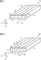
- the three first slits 121 have an identical depth.
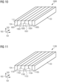
- the first slits may have a different length as may be seen in Figures 10 to 13 .
- the three first ends 141 of the first slit 121 are arranged on a first connecting line 151 of the first slits 121 which is distanced to the first side 131 and to the second side 132.
- a distance between the second side 132 and the first connecting line 151 of the first slits 121 is smaller than a distance between the first side 131 and the first connecting line 151 of the first slits 121.
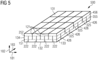
- the base body 110 is formed with four second slits 222. Seen in the first direction 181 from the fourth side 134 to the third side 133, there is a first second slit 222, a first first slit 121, a second second slit 222, a second first slit 121, a third second slit 222, a third first slit 121 and a fourth second slit 222. A total distance in the first direction 181 is the length between the fourth side 134 and the third side 133.
- the three first slits 121 are formed identical to the three first slits in Fig. 1 .
- the four second slits 222 are each formed as blind holes ending inside the base body 210. As exemplarily shown in Fig. 2 only on one second slit 222, each of the four second slits 222 comprises a first end 242 of the second slit 222. The first end 242 of the second slit 222 is a bottom of the blind hole at which the second slit 121 ends in the base body 210. Additionally, each of the four second slits 222 comprises a second end 262 of the second slit 222 where the second slit 222 opens to the second side 132.
- a distance between the second side 132 and the first connecting line 151 of the first slits 121 could be equal or larger than a distance between the first side 131 and the first connecting line 151 of the first slits 121 (not shown in Fig. 2 ).
- the second connecting line 252 of the second slits 222 is parallel to the first side 131 and the second side 132, respectively.
- the three first slits 121 and the four second slits 222 extend parallel to each other and extend such that they never cross each other or are connected in any way.
- the base body 410 is formed with three fifth slits 325 and four sixth slits 426. Seen in the third direction 183 from the first end surface 111 to the second end surface, there is a first sixth slit 426, a first fifth slit 325, a second sixth slit 426, a second fifth slit 325, a third sixth slit 426, a third fifth slit 325 and a fourth sixth slit 426. A total distance in the third direction 183 is the length between the first end surface 111 and the second end surface being parallel to the first end surface 111.
- the three fifth slits 325 and the four sixth slits 426 are each formed as respective blind holes in the base body 410.
- each of the four sixth slits 426 comprises a first end 444 of the sixth slit 426.
- the first end 444 of the sixth slit 426 is a bottom of the blind hole at which the sixth slit 426 ends inside the base body 410.
- each of the four sixth slits 426 comprises a second end 464 of the sixth slit 426 where the sixth slit 426 opens to the first side 131.
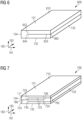
- Fig. 6 shows a cross-sectional view of a permanent magnet 600 comprising one third slit 623 according to an example.
- Fig. 7 shows a cross-sectional view of a permanent magnet 700 comprising two third slits 723 and one fourth slit 724 according to an example.
- Fig. 9 shows a cross-sectional view of a permanent magnet 900 comprising two first slits 921 and two second slits 922 according to a further example.
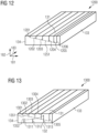
- a first connecting line 1351 connecting the bottom of each of the first slits 1301, 1302, 1303, 1304, and 1305 with each other has the shape of a straight line having an inclination relatively to the first side 131 and the second side 132, respectively.
- a second connecting line 1352 connecting the bottom of each of the second slits 1311, 1312, and 1313 with each other has the shape of a parabola.
Landscapes
- Engineering & Computer Science (AREA)
- Power Engineering (AREA)
- Manufacturing & Machinery (AREA)
- Physics & Mathematics (AREA)
- Electromagnetism (AREA)
- Permanent Field Magnets Of Synchronous Machinery (AREA)
Claims (13)
- Dauermagnet (100) für eine Dauermagnetmaschine, der Folgendes umfasst:einen Basiskörper (810) mit einer ersten Seite (131) und einer zweiten Seite (132), bei der es sich um die der ersten Seite (131) gegenüberliegende Seite handelt,wobei der Basiskörper (810) ferner eine dritte Seite (133) und eine vierte Seite (134), bei der es sich um eine der dritten Seite (133) gegenüberliegende Seite handelt, umfasst und wobei die dritte Seite (133) und die vierte Seite (134) die erste Seite (131) und die zweite Seite (132) miteinander verbinden,wobei erste Schlitze (821) und weitere erste Schlitze (821) derart in dem Basiskörper (810) ausgebildet sind, dass sich die ersten Schlitze (821) und die weiteren ersten Schlitze (821) von der ersten Seite (131) in die Richtung der zweiten Seite (132) erstrecken,wobei sich die ersten Schlitze (821) und die weiteren ersten Schlitze (821) von der ersten Seite (131) in die Richtung der zweiten Seite (132) ohne eine Öffnung in der zweiten Seite (132) erstrecken, so dass die ersten Schlitze (821) und die weiteren ersten Schlitze (121) jeweilige Sacklöcher bilden, die in dem Basiskörper (810) enden,wobei die Tiefe der ersten Schlitze (821) und der weiteren ersten Schlitze (821) zwischen einer Flächenposition auf der ersten Seite (131), an der die jeweiligen ersten Schlitze (821) oder die weiteren ersten Schlitze (821) zu der ersten Seite (131) hin offen sind, und dem Boden der jeweiligen ersten Schlitze (821) oder der weiteren ersten Schlitze (821) gemessen wird,wobei der Basiskörper (810) monolithisch als ein einstückiges Element aus einem magnetischen Material ausgebildet ist,wobei der Dauermagnet Magnetwirbelstromverluste reduzieren kann,wobei jeder der ersten Schlitze (821) eine Erstreckung aufweist, die zur ersten Seite (131) gekröpft ist,wobei die zwei ersten Schlitze (821) so gekröpft sind, dass ein spitzer Winkel zwischen der ersten Seite (131) und dem ersten Schlitz (821) in die Richtung der dritten Seite (133) definiert wird,dadurch gekennzeichnet, dasszwei andere erste Schlitze (821) so gekröpft sind, dass ein spitzer Winkel zwischen der ersten Seite (131) und dem ersten Schlitz (821) in der Richtung der vierten Seite (134) definiert wird.
- Dauermagnet (800) nach Anspruch 1,wobei der Basiskörper (810) so ausgebildet ist, dass der Winkel zwischen dem mindestens einen ersten Schlitz (821) und der ersten Seite (131) gebildet wird,wobei der Winkel im Bereich von 0° bis 180°, speziell 45° bis 135°, liegt.
- Dauermagnet (100) nach Anspruch 1 oder 2,
wobei der Basiskörper (110) so ausgebildet ist, dass sich der mindestens eine erste Schlitz (821) von der ersten Seite (131) in die Richtung der zweiten Seite (132) über mehr als mindestens 1 %, speziell mindestens 25 %, spezieller um mehr als 50 %, noch spezieller 80 %, einer Strecke zwischen der ersten Seite (131) und der zweiten Seite (132) erstreckt. - Dauermagnet (100) nach einem der Ansprüche 1-3,
wobei der mindestens eine erste Schlitz (821) so in dem Basiskörper (110) ausgebildet ist, dass der mindestens eine erste Schlitz (821) in einer Querschnittsansicht des Basiskörpers (110) eine gerade, gezackte und/oder gewellte Form aufweist. - Dauermagnet (600) nach einem der Ansprüche 1-4,
wobei mindestens ein dritter Schlitz (623) so in dem Basiskörper (610) ausgebildet ist, dass sich der mindestens eine dritte Schlitz (623) von der dritten Seite (133) in die Richtung der vierten Seite (134) erstreckt. - Dauermagnet (700) nach einem der Ansprüche 1-5,
wobei mindestens ein vierter Schlitz (724) so in dem Basiskörper (710) ausgebildet ist, dass sich der mindestens eine vierte Schlitz (724) von der vierten Seite (134) in die Richtung der dritten Seite (133) erstreckt. - Dauermagnet (100) nach einem der Ansprüche 1-6,wobei eine erste Richtung (181) parallel zur ersten Seite (131) verläuft,wobei eine zweite Richtung (182) parallel zur dritten Seite (133) verläuft,wobei eine dritte Richtung (183) senkrecht zu der ersten Richtung (181) und der zweiten Richtung (182) verläuft, und wobei sich der mindestens eine erste Schlitz (821) in der dritten Richtung (183) komplett durch den Basiskörper (110) hindurch erstreckt.
- Dauermagnet (100) für eine Dauermagnetmaschine, der Folgendes umfasst:einen Basiskörper (910) mit einer ersten Seite (131) und einer zweiten Seite (132), bei der es sich um die der ersten Seite (131) gegenüberliegende Seite handelt,wobei der Basiskörper (810) ferner eine dritte Seite (133) und eine vierte Seite (134), bei der es sich um eine der dritten Seite (133) gegenüberliegende Seite handelt, umfasst und wobei die dritte Seite (133) und die vierte Seite (134) die erste Seite (131) und die zweite Seite (132) miteinander verbinden,wobei erste Schlitze (921) und weitere erste Schlitze (921) derart in dem Basiskörper (910) ausgebildet sind, dass sich die ersten Schlitze (921) und die weiteren ersten Schlitze (921) von der ersten Seite (131) in die Richtung der zweiten Seite (132) erstrecken,wobei sich die ersten Schlitze (921) und die weiteren ersten Schlitze (921) von der ersten Seite (131) in die Richtung der zweiten Seite (132) ohne eine Öffnung in der zweiten Seite (132) erstrecken, so dass die ersten Schlitze (921) und die weiteren ersten Schlitze (921) jeweilige Sacklöcher bilden,die in dem Basiskörper (910) enden,wobei die Tiefe der ersten Schlitze (921) und der weiteren ersten Schlitze (921) zwischen einer Flächenposition auf der ersten Seite (131), an der die jeweiligen ersten Schlitze (121) oder die weiteren ersten Schlitze (921) zu der ersten Seite (131) hin offen sind, und dem Boden der jeweiligen ersten Schlitze (921) oder der weiteren ersten Schlitze (921) gemessen wird,wobei der Basiskörper (910) monolithisch als ein einstückiges Element aus einem magnetischen Material ausgebildet ist,wobei der Dauermagnet Magnetwirbelstromverluste reduzieren kann,dadurch gekennzeichnet, dasszweite Schlitze (922) so in dem Basiskörper (210) ausgebildet sind, dass sich die zweiten Schlitze (922) von der zweiten Seite (132) in die Richtung der ersten Seite (131) erstrecken,wobei mindestens zwei der ersten Schlitze (921) bezüglich der ersten Seite (131) gekröpft sind und ein spitzer Winkel zwischen der ersten Seite (131) und einer Erstreckung eines der zwei ersten Schlitze (921) in der Richtung der dritten Seite (133) verläuft und ein spitzer Winkel zwischen der ersten Seite (131) und einer Erstreckung des anderen der zwei ersten Schlitze (921) in der Richtung der vierten Seite (134) verläuft,wobei mindestens zwei zweite Schlitze (922) parallel zueinander sind und bezüglich der zweiten Seite (132) gekröpft sind.
- Dauermagnet (100) für eine Dauermagnetmaschine, der Folgendes umfasst:einen Basiskörper (110) mit einer ersten Seite (131) und einer zweiten Seite (132), bei der es sich um die der ersten Seite (131) gegenüberliegende Seite handelt,wobei der Basiskörper (810) ferner eine dritte Seite (133) und eine vierte Seite (134), bei der es sich um eine der dritten Seite (133) gegenüberliegende Seite handelt, umfasst und wobei die dritte Seite (133) und die vierte Seite (134) die erste Seite (131) und die zweite Seite (132) miteinander verbinden,wobei erste Schlitze (1001 bis 1005) derart in dem Basiskörper (110) ausgebildet sind, dass sich die ersten Schlitze (1001 bis 1005) von der ersten Seite (131) in die Richtung der zweiten Seite (132) erstrecken,wobei sich die ersten Schlitze (1001 bis 1005) von der ersten Seite (131) in die Richtung der zweiten Seite (132) ohne eine Öffnung in der zweiten Seite (132) erstrecken, so dass die ersten Schlitze (1001 bis 1005) jeweilige Sacklöcher bilden, die in dem Basiskörper (110) enden,wobei die Tiefe der ersten Schlitze (1001 bis 1005) zwischen einer Flächenposition auf der ersten Seite (131), an der die jeweiligen ersten Schlitze (1001 bis 1005) zu der ersten Seite (131) hin offen sind, und dem Boden der jeweiligen ersten Schlitze (1001 bis 1005) gemessen wird,wobei der Basiskörper (110) monolithisch als ein einstückiges Element aus einem magnetischen Material ausgebildet ist,wobei der Dauermagnet Magnetwirbelstromverluste reduzieren kann,wobei eine erste Richtung (181) parallel zur ersten Seite (131) verläuft,dadurch gekennzeichnet, dasseine erste Tiefe des ersten ersten Schlitzes (1001) größer als die zweite Tiefe des zweiten ersten Schlitzes (1002), die dritte Tiefe des dritten ersten Schlitzes (1003) und die vierte Tiefe des vierten ersten Schlitzes (1004) und gleich der fünften Tiefe des fünften ersten Schlitzes (1005) ist,wobei eine zweite Tiefe des zweiten ersten Schlitzes (1002) größer als die dritte Tiefe des dritten ersten Schlitzes (1003) und gleich der vierten Tiefe des vierten ersten Schlitzes (1004) ist, so dass eine Verbindungslinie (1051), die die Böden aller ersten Schlitze (1001, 1002, 1003, 1004, 1005) miteinander verbindet, eine dreieckige Form aufweist.
- Dauermagnetmaschine, die Folgendes umfasst:einen Basiskörper (110) mit einer ersten Seite (131) und einer zweiten Seite (132), bei der es sich um die der ersten Seite (131) gegenüberliegende Seite handelt,wobei der Basiskörper (810) ferner eine dritte Seite (133) und eine vierte Seite (134), bei der es sich um eine der dritten Seite (133) gegenüberliegende Seite handelt, umfasst und wobei die dritte Seite (133) und die vierte Seite (134) die erste Seite (131) und die zweite Seite (132) miteinander verbinden,wobei erste Schlitze (1101 bis 1105) derart in dem Basiskörper (110) ausgebildet sind, dass sich die ersten Schlitze (1101 bis 1105) von der ersten Seite (131) in die Richtung der zweiten Seite (132) erstrecken,wobei sich die ersten Schlitze (1101 bis 1105) von der ersten Seite (131) in die Richtung der zweiten Seite (132) ohne eine Öffnung in der zweiten Seite (132) erstrecken, so dass die ersten Schlitze (1101 bis 1105) jeweilige Sacklöcher bilden, die in dem Basiskörper (110) enden,wobei die Tiefe der ersten Schlitze (1101 bis 1105) zwischen einer Flächenposition auf der ersten Seite (131), an der die jeweiligen ersten Schlitze (1101 bis 1105) zu der ersten Seite (131) hin offen sind, und dem Boden der jeweiligen ersten Schlitze (1101 bis 1105) gemessen wird,wobei der Basiskörper (110) monolithisch als ein einstückiges Element aus einem magnetischen Material ausgebildet ist,wobei der Dauermagnet Magnetwirbelstromverluste reduzieren kann,wobei eine erste Richtung (181) parallel zur ersten Seite (131) verläuft,dadurch gekennzeichnet, dassbei Betrachtung in der ersten Richtung (181) von der vierten Seite (134) zu der dritten Seite (133) ein erster erster Schlitz (1101), ein zweiter erster Schlitz (1102), ein dritter erster Schlitz (1103), ein vierter erster Schlitz (1104) und ein fünfter erster Schlitz (1105) der ersten Schlitze (1101 bis 1105) angeordnet sind,wobei die erste Tiefe des ersten ersten Schlitzes (1101) gleich der dritten Tiefe des dritten ersten Schlitzes (1103) und der fünften Tiefe des fünften ersten Schlitzes (1105) ist, undwobei die zweite Tiefe des zweiten ersten Schlitzes (1102) gleich der vierten Tiefe des vierten ersten Schlitzes (1104) und kleiner als die erste Tiefe des ersten ersten Schlitzes (1101) ist, so dass eine Verbindungslinie (1151), die die Böden aller ersten Schlitze (1101, 1102, 1103, 1104 und 1105) miteinander verbindet, die Form einer Zickzacklinie aufweist.
- Dauermagnet (100) für eine Dauermagnetmaschine, der Folgendes umfasst:einen Basiskörper (110) mit einer ersten Seite (131) und einer zweiten Seite (132), bei der es sich um die der ersten Seite (131) gegenüberliegende Seite handelt,wobei der Basiskörper (810) ferner eine dritte Seite (133) und eine vierte Seite (134), bei der es sich um eine der dritten Seite (133) gegenüberliegende Seite handelt, umfasst und wobei die dritte Seite (133) und die vierte Seite (134) die erste Seite (131) und die zweite Seite (132) miteinander verbinden,wobei erste Schlitze (1201 bis 1206) derart in dem Basiskörper (110) ausgebildet sind, dass sich die ersten Schlitze (1201 bis 1206) von der ersten Seite (131) in die Richtung der zweiten Seite (132) erstrecken,wobei sich die ersten Schlitze (1201 bis 1206) von der ersten Seite (131) in die Richtung der zweiten Seite (132) ohne eine Öffnung in der zweiten Seite (132) erstrecken, so dass die ersten Schlitze (1201 bis 1206) jeweilige Sacklöcher bilden, die in dem Basiskörper (110) enden,wobei die Tiefe der ersten Schlitze (1201 bis 1206) zwischen einer Flächenposition auf der ersten Seite (131), an der die jeweiligen ersten Schlitze (1201 bis 1206) zu der ersten Seite (131) hin offen sind, und dem Boden der jeweiligen ersten Schlitze (1201 bis 1206) gemessen wird,wobei der Basiskörper (110) monolithisch als ein einstückiges Element aus einem magnetischen Material ausgebildet ist,wobei der Dauermagnet Magnetwirbelstromverluste reduzieren kann,wobei eine erste Richtung (181) parallel zur ersten Seite (131) verläuft,dadurch gekennzeichnet, dassbei Betrachtung in der ersten Richtung (181) von der vierten Seite (134) zu der dritten Seite (133) mindestens sechs erste Schlitze (1201 bis 1206) in einer Reihenfolge angeordnet sind, die von ihrer zunehmenden Tiefe abhängig ist, so dass eine Verbindungslinie 1251, die die Böden aller ersten Schlitze (1201 bis 1206) miteinander verbindet, die Form einer geraden Linie mit einer Neigung bezüglich der ersten Seite (131) aufweist.
- Dauermagnet (100) für eine Dauermagnetmaschine, der Folgendes umfasst:einen Basiskörper (110) mit einer ersten Seite (131) und einer zweiten Seite (132), bei der es sich um die der ersten Seite (131) gegenüberliegende Seite handelt,wobei der Basiskörper (810) ferner eine dritte Seite (133) und eine vierte Seite (134), bei der es sich um eine der dritten Seite (133) gegenüberliegende Seite handelt, umfasst und wobei die dritte Seite (133) und die vierte Seite (134) die erste Seite (131) und die zweite Seite (132) miteinander verbinden,wobei erste Schlitze (1301 bis 1305) derart in dem Basiskörper (110) ausgebildet sind, dass sich die ersten Schlitze (1301 bis 1305) von der ersten Seite (131) in die Richtung der zweiten Seite (132) erstrecken,wobei sich die ersten Schlitze (1301 bis 1305) von der ersten Seite (131) in die Richtung der zweiten Seite (132) ohne eine Öffnung in der zweiten Seite (132) erstrecken, so dass die ersten Schlitze (1301 bis 1305) jeweilige Sacklöcher bilden, die in dem Basiskörper (110) enden,wobei die Tiefe der ersten Schlitze (1301 bis 1305) zwischen einer Flächenposition auf der ersten Seite (131), an der die jeweiligen ersten Schlitze (1301 bis 1305) zu der ersten Seite (131) hin offen sind, und dem Boden der jeweiligen ersten Schlitze (1301 bis 1305) gemessen wird,wobei der Basiskörper (110) monolithisch als ein einstückiges Element aus einem magnetischen Material ausgebildet ist,wobei der Dauermagnet Magnetwirbelstromverluste reduzieren kann,wobei eine erste Richtung (181) parallel zur ersten Seite (131) verläuft,dadurch gekennzeichnet, dasszweite Schlitze (1) so in dem Basiskörper (210) ausgebildet sind, dass sich die zweiten Schlitze (1301 bis 1305) von der zweiten Seite (132) in die Richtung der ersten Seite (131) erstrecken,wobei bei Betrachtung in der ersten Richtung (181) von der vierten Seite (134) zu der dritten Seite (133) von den ersten Schlitzen (1301 bis 1305) und den zweiten Schlitzen (1311 bis 1313) der erste erste Schlitz (1301), der erste zweite Schlitz (1311), der zweite erste Schlitz (1302), der zweite zweite Schlitz (1312), der dritte erste Schlitz (1303), der vierte erste Schlitz (1304), der dritte zweite Schlitz (1313) und der fünfte erste Schlitz (1305) so angeordnet sind, dass eine erste Verbindungslinie (1351), die die Böden aller ersten Schlitze (1301, 1302, 1303, 1304, 1305) miteinander verbindet, die Form einer geraden Linie mit einer Neigung bezüglich der ersten Seite (131) und der zweiten Seite (132) aufweist,wobei eine Zweitverbindungslinie (1352), die die Böden aller drei zweiten Schlitze (1311, 1312, 1313) miteinander verbindet, parabelförmig ist.
- Dauermagnetmaschine, die Folgendes umfasst:einen Dauermagneten (100) nach einem der Ansprüche 1-12, undeine Komponente, die ein Magnetfeld erzeugt.
Priority Applications (4)
| Application Number | Priority Date | Filing Date | Title |
|---|---|---|---|
| EP17191422.9A EP3457532B1 (de) | 2017-09-15 | 2017-09-15 | Dauermagnet für eine dauermagnetmaschine |
| US16/127,320 US11004586B2 (en) | 2017-09-15 | 2018-09-11 | Permanent magnet for a permanent magnet machine |
| EP18194347.3A EP3457535B1 (de) | 2017-09-15 | 2018-09-13 | Dauermagnet für eine dauermagnetmaschine |
| CN201811080920.3A CN109510329B (zh) | 2017-09-15 | 2018-09-17 | 用于永磁电机的永磁体及其制造方法 |
Applications Claiming Priority (1)
| Application Number | Priority Date | Filing Date | Title |
|---|---|---|---|
| EP17191422.9A EP3457532B1 (de) | 2017-09-15 | 2017-09-15 | Dauermagnet für eine dauermagnetmaschine |
Publications (2)
| Publication Number | Publication Date |
|---|---|
| EP3457532A1 EP3457532A1 (de) | 2019-03-20 |
| EP3457532B1 true EP3457532B1 (de) | 2023-02-01 |
Family
ID=59887160
Family Applications (1)
| Application Number | Title | Priority Date | Filing Date |
|---|---|---|---|
| EP17191422.9A Active EP3457532B1 (de) | 2017-09-15 | 2017-09-15 | Dauermagnet für eine dauermagnetmaschine |
Country Status (1)
| Country | Link |
|---|---|
| EP (1) | EP3457532B1 (de) |
Families Citing this family (5)
| Publication number | Priority date | Publication date | Assignee | Title |
|---|---|---|---|---|
| CN115811153A (zh) * | 2021-09-14 | 2023-03-17 | 博泽沃尔兹堡汽车零部件欧洲两合公司 | 用于电机的磁体元件 |
| CN115346791B (zh) * | 2022-09-02 | 2025-09-19 | 浙江盘毂动力科技有限公司 | 一种磁性元件的制造方法 |
| DE102022132795A1 (de) * | 2022-12-09 | 2024-06-20 | Schaeffler Technologies AG & Co. KG | Magnet für einen Rotor, Rotor mit Magnet, Elektromaschine / Axialflussmaschine und Herstellverfahren |
| DE102023004778A1 (de) | 2023-11-22 | 2025-05-22 | Mercedes-Benz Group AG | Segmentierungsanordnung für Permanentmagnete einer Doppel-V-Anordnung in einem Rotor für eine permanenterregte elektrische Maschine |
| EP4682917A1 (de) * | 2024-07-16 | 2026-01-21 | Siemens Aktiengesellschaft | Magnet für eine permanenterregte synchronmaschine |
Citations (3)
| Publication number | Priority date | Publication date | Assignee | Title |
|---|---|---|---|---|
| US20100244608A1 (en) * | 2007-12-06 | 2010-09-30 | Toyota Jidosha Kabushiki Kaisha | Permanent magnet, manufacturing method thereof, and rotor and ipm motor |
| US20130057374A1 (en) * | 2010-05-19 | 2013-03-07 | Nissan Motor Co., Ltd. | Permanent magnet disposed in rotating electrical machine and manufacturing method of the same |
| EP2811628B1 (de) * | 2012-02-01 | 2015-11-18 | Nissan Motor Co., Ltd. | Verfahren zur herstellung von magnetteilen zur formung von feldpolmagneten |
Family Cites Families (5)
| Publication number | Priority date | Publication date | Assignee | Title |
|---|---|---|---|---|
| DE60014780T2 (de) * | 1999-06-30 | 2005-03-10 | Shin-Etsu Chemical Co., Ltd. | Auf seltenen Erden basierender gesinterter Dauermagnet und mit einem solchen Magnet versehener Synchronmotor |
| JP4734957B2 (ja) * | 2005-02-24 | 2011-07-27 | トヨタ自動車株式会社 | ロータ |
| JP4962870B2 (ja) * | 2007-06-29 | 2012-06-27 | 日産自動車株式会社 | 界磁極用磁石体の製造方法、永久磁石型回転電動機の製造方法及び界磁極用磁石体 |
| JP5911358B2 (ja) * | 2012-04-09 | 2016-04-27 | 三菱電機株式会社 | 希土類永久磁石、希土類永久磁石の製造方法、および、モータ |
| DE102013211858A1 (de) * | 2013-06-21 | 2014-12-24 | Robert Bosch Gmbh | Oberflächen- Magnete und vergrabene Magnete für einen Rotor oder Stator einer elektrischen Maschine, der eine Haltegeometrie aufweist |
-
2017
- 2017-09-15 EP EP17191422.9A patent/EP3457532B1/de active Active
Patent Citations (3)
| Publication number | Priority date | Publication date | Assignee | Title |
|---|---|---|---|---|
| US20100244608A1 (en) * | 2007-12-06 | 2010-09-30 | Toyota Jidosha Kabushiki Kaisha | Permanent magnet, manufacturing method thereof, and rotor and ipm motor |
| US20130057374A1 (en) * | 2010-05-19 | 2013-03-07 | Nissan Motor Co., Ltd. | Permanent magnet disposed in rotating electrical machine and manufacturing method of the same |
| EP2811628B1 (de) * | 2012-02-01 | 2015-11-18 | Nissan Motor Co., Ltd. | Verfahren zur herstellung von magnetteilen zur formung von feldpolmagneten |
Also Published As
| Publication number | Publication date |
|---|---|
| EP3457532A1 (de) | 2019-03-20 |
Similar Documents
| Publication | Publication Date | Title |
|---|---|---|
| EP3457535B1 (de) | Dauermagnet für eine dauermagnetmaschine | |
| EP3457532A1 (de) | Dauermagnet für eine dauermagnetmaschine | |
| KR100386314B1 (ko) | 철심장치 | |
| EP3273580B1 (de) | Verfahren zur herstellung eines laminierten eisenkerns und vorrichtung zur herstellung eines laminierten eisenkerns | |
| TWI523378B (zh) | Manufacture of coils and coils | |
| JP4365271B2 (ja) | 積層型鉄心の製造方法 | |
| US11456629B2 (en) | Stator with divided cores connected circumferentially | |
| KR20190035888A (ko) | 회전자 및 자기 저항 모터 | |
| US10291092B2 (en) | Rotor and motor including the same | |
| JP4730461B2 (ja) | 磁芯の製造方法 | |
| JP6169505B2 (ja) | 回転子積層鉄心の製造方法 | |
| JP6293712B2 (ja) | 電機子および電機子の製造方法 | |
| JP5683045B2 (ja) | 巻線成形装置および巻線成形方法 | |
| CN108988533B (zh) | 转子铁芯及具有其的永磁同步电机 | |
| JP6934714B2 (ja) | 積層鉄心の製造方法及び積層鉄心 | |
| JP2009065833A (ja) | 積層型鉄心及びその製造方法 | |
| US10826362B2 (en) | Laminated iron core and method for manufacturing same | |
| JPH11346447A (ja) | 鉄 心 | |
| JP5154398B2 (ja) | 積層型鉄心の製造方法及び積層型固定子の製造方法 | |
| EP4492638A1 (de) | Laminierter kern, rotor und herstellungsverfahren für einen laminierten kern | |
| JP2022152174A (ja) | ステータ及びステータの製造方法 | |
| JP6926874B2 (ja) | ロータ | |
| JP4748315B2 (ja) | フェライトシート | |
| US10811921B2 (en) | Insulating member and stator | |
| JP2007082282A (ja) | ステータコア、それを用いたモータ及びその製造方法 |
Legal Events
| Date | Code | Title | Description |
|---|---|---|---|
| PUAI | Public reference made under article 153(3) epc to a published international application that has entered the european phase |
Free format text: ORIGINAL CODE: 0009012 |
|
| STAA | Information on the status of an ep patent application or granted ep patent |
Free format text: STATUS: THE APPLICATION HAS BEEN PUBLISHED |
|
| AK | Designated contracting states |
Kind code of ref document: A1 Designated state(s): AL AT BE BG CH CY CZ DE DK EE ES FI FR GB GR HR HU IE IS IT LI LT LU LV MC MK MT NL NO PL PT RO RS SE SI SK SM TR |
|
| AX | Request for extension of the european patent |
Extension state: BA ME |
|
| STAA | Information on the status of an ep patent application or granted ep patent |
Free format text: STATUS: REQUEST FOR EXAMINATION WAS MADE |
|
| 17P | Request for examination filed |
Effective date: 20190605 |
|
| RBV | Designated contracting states (corrected) |
Designated state(s): AL AT BE BG CH CY CZ DE DK EE ES FI FR GB GR HR HU IE IS IT LI LT LU LV MC MK MT NL NO PL PT RO RS SE SI SK SM TR |
|
| STAA | Information on the status of an ep patent application or granted ep patent |
Free format text: STATUS: EXAMINATION IS IN PROGRESS |
|
| 17Q | First examination report despatched |
Effective date: 20200217 |
|
| REG | Reference to a national code |
Ref country code: DE Ref legal event code: R079 Ref document number: 602017065873 Country of ref document: DE Free format text: PREVIOUS MAIN CLASS: H02K0001270000 Ipc: H01F0007020000 |
|
| RIC1 | Information provided on ipc code assigned before grant |
Ipc: H01F 41/02 20060101ALI20200818BHEP Ipc: H02K 15/03 20060101ALI20200818BHEP Ipc: H01F 7/02 20060101AFI20200818BHEP |
|
| GRAP | Despatch of communication of intention to grant a patent |
Free format text: ORIGINAL CODE: EPIDOSNIGR1 |
|
| STAA | Information on the status of an ep patent application or granted ep patent |
Free format text: STATUS: GRANT OF PATENT IS INTENDED |
|
| GRAJ | Information related to disapproval of communication of intention to grant by the applicant or resumption of examination proceedings by the epo deleted |
Free format text: ORIGINAL CODE: EPIDOSDIGR1 |
|
| STAA | Information on the status of an ep patent application or granted ep patent |
Free format text: STATUS: EXAMINATION IS IN PROGRESS |
|
| INTG | Intention to grant announced |
Effective date: 20220718 |
|
| GRAP | Despatch of communication of intention to grant a patent |
Free format text: ORIGINAL CODE: EPIDOSNIGR1 |
|
| STAA | Information on the status of an ep patent application or granted ep patent |
Free format text: STATUS: GRANT OF PATENT IS INTENDED |
|
| INTC | Intention to grant announced (deleted) | ||
| INTG | Intention to grant announced |
Effective date: 20220907 |
|
| GRAS | Grant fee paid |
Free format text: ORIGINAL CODE: EPIDOSNIGR3 |
|
| GRAA | (expected) grant |
Free format text: ORIGINAL CODE: 0009210 |
|
| STAA | Information on the status of an ep patent application or granted ep patent |
Free format text: STATUS: THE PATENT HAS BEEN GRANTED |
|
| AK | Designated contracting states |
Kind code of ref document: B1 Designated state(s): AL AT BE BG CH CY CZ DE DK EE ES FI FR GB GR HR HU IE IS IT LI LT LU LV MC MK MT NL NO PL PT RO RS SE SI SK SM TR |
|
| REG | Reference to a national code |
Ref country code: GB Ref legal event code: FG4D |
|
| REG | Reference to a national code |
Ref country code: CH Ref legal event code: EP Ref country code: AT Ref legal event code: REF Ref document number: 1547133 Country of ref document: AT Kind code of ref document: T Effective date: 20230215 |
|
| REG | Reference to a national code |
Ref country code: DE Ref legal event code: R096 Ref document number: 602017065873 Country of ref document: DE |
|
| REG | Reference to a national code |
Ref country code: IE Ref legal event code: FG4D |
|
| REG | Reference to a national code |
Ref country code: LT Ref legal event code: MG9D |
|
| REG | Reference to a national code |
Ref country code: NL Ref legal event code: MP Effective date: 20230201 |
|
| REG | Reference to a national code |
Ref country code: AT Ref legal event code: MK05 Ref document number: 1547133 Country of ref document: AT Kind code of ref document: T Effective date: 20230201 |
|
| PG25 | Lapsed in a contracting state [announced via postgrant information from national office to epo] |
Ref country code: RS Free format text: LAPSE BECAUSE OF FAILURE TO SUBMIT A TRANSLATION OF THE DESCRIPTION OR TO PAY THE FEE WITHIN THE PRESCRIBED TIME-LIMIT Effective date: 20230201 Ref country code: PT Free format text: LAPSE BECAUSE OF FAILURE TO SUBMIT A TRANSLATION OF THE DESCRIPTION OR TO PAY THE FEE WITHIN THE PRESCRIBED TIME-LIMIT Effective date: 20230601 Ref country code: NO Free format text: LAPSE BECAUSE OF FAILURE TO SUBMIT A TRANSLATION OF THE DESCRIPTION OR TO PAY THE FEE WITHIN THE PRESCRIBED TIME-LIMIT Effective date: 20230501 Ref country code: NL Free format text: LAPSE BECAUSE OF FAILURE TO SUBMIT A TRANSLATION OF THE DESCRIPTION OR TO PAY THE FEE WITHIN THE PRESCRIBED TIME-LIMIT Effective date: 20230201 Ref country code: LV Free format text: LAPSE BECAUSE OF FAILURE TO SUBMIT A TRANSLATION OF THE DESCRIPTION OR TO PAY THE FEE WITHIN THE PRESCRIBED TIME-LIMIT Effective date: 20230201 Ref country code: LT Free format text: LAPSE BECAUSE OF FAILURE TO SUBMIT A TRANSLATION OF THE DESCRIPTION OR TO PAY THE FEE WITHIN THE PRESCRIBED TIME-LIMIT Effective date: 20230201 Ref country code: HR Free format text: LAPSE BECAUSE OF FAILURE TO SUBMIT A TRANSLATION OF THE DESCRIPTION OR TO PAY THE FEE WITHIN THE PRESCRIBED TIME-LIMIT Effective date: 20230201 Ref country code: ES Free format text: LAPSE BECAUSE OF FAILURE TO SUBMIT A TRANSLATION OF THE DESCRIPTION OR TO PAY THE FEE WITHIN THE PRESCRIBED TIME-LIMIT Effective date: 20230201 Ref country code: AT Free format text: LAPSE BECAUSE OF FAILURE TO SUBMIT A TRANSLATION OF THE DESCRIPTION OR TO PAY THE FEE WITHIN THE PRESCRIBED TIME-LIMIT Effective date: 20230201 |
|
| PG25 | Lapsed in a contracting state [announced via postgrant information from national office to epo] |
Ref country code: SE Free format text: LAPSE BECAUSE OF FAILURE TO SUBMIT A TRANSLATION OF THE DESCRIPTION OR TO PAY THE FEE WITHIN THE PRESCRIBED TIME-LIMIT Effective date: 20230201 Ref country code: PL Free format text: LAPSE BECAUSE OF FAILURE TO SUBMIT A TRANSLATION OF THE DESCRIPTION OR TO PAY THE FEE WITHIN THE PRESCRIBED TIME-LIMIT Effective date: 20230201 Ref country code: IS Free format text: LAPSE BECAUSE OF FAILURE TO SUBMIT A TRANSLATION OF THE DESCRIPTION OR TO PAY THE FEE WITHIN THE PRESCRIBED TIME-LIMIT Effective date: 20230601 Ref country code: GR Free format text: LAPSE BECAUSE OF FAILURE TO SUBMIT A TRANSLATION OF THE DESCRIPTION OR TO PAY THE FEE WITHIN THE PRESCRIBED TIME-LIMIT Effective date: 20230502 Ref country code: FI Free format text: LAPSE BECAUSE OF FAILURE TO SUBMIT A TRANSLATION OF THE DESCRIPTION OR TO PAY THE FEE WITHIN THE PRESCRIBED TIME-LIMIT Effective date: 20230201 |
|
| PG25 | Lapsed in a contracting state [announced via postgrant information from national office to epo] |
Ref country code: SM Free format text: LAPSE BECAUSE OF FAILURE TO SUBMIT A TRANSLATION OF THE DESCRIPTION OR TO PAY THE FEE WITHIN THE PRESCRIBED TIME-LIMIT Effective date: 20230201 Ref country code: RO Free format text: LAPSE BECAUSE OF FAILURE TO SUBMIT A TRANSLATION OF THE DESCRIPTION OR TO PAY THE FEE WITHIN THE PRESCRIBED TIME-LIMIT Effective date: 20230201 Ref country code: EE Free format text: LAPSE BECAUSE OF FAILURE TO SUBMIT A TRANSLATION OF THE DESCRIPTION OR TO PAY THE FEE WITHIN THE PRESCRIBED TIME-LIMIT Effective date: 20230201 Ref country code: DK Free format text: LAPSE BECAUSE OF FAILURE TO SUBMIT A TRANSLATION OF THE DESCRIPTION OR TO PAY THE FEE WITHIN THE PRESCRIBED TIME-LIMIT Effective date: 20230201 Ref country code: CZ Free format text: LAPSE BECAUSE OF FAILURE TO SUBMIT A TRANSLATION OF THE DESCRIPTION OR TO PAY THE FEE WITHIN THE PRESCRIBED TIME-LIMIT Effective date: 20230201 |
|
| REG | Reference to a national code |
Ref country code: DE Ref legal event code: R097 Ref document number: 602017065873 Country of ref document: DE |
|
| PG25 | Lapsed in a contracting state [announced via postgrant information from national office to epo] |
Ref country code: SK Free format text: LAPSE BECAUSE OF FAILURE TO SUBMIT A TRANSLATION OF THE DESCRIPTION OR TO PAY THE FEE WITHIN THE PRESCRIBED TIME-LIMIT Effective date: 20230201 |
|
| PLBE | No opposition filed within time limit |
Free format text: ORIGINAL CODE: 0009261 |
|
| STAA | Information on the status of an ep patent application or granted ep patent |
Free format text: STATUS: NO OPPOSITION FILED WITHIN TIME LIMIT |
|
| 26N | No opposition filed |
Effective date: 20231103 |
|
| PG25 | Lapsed in a contracting state [announced via postgrant information from national office to epo] |
Ref country code: SI Free format text: LAPSE BECAUSE OF FAILURE TO SUBMIT A TRANSLATION OF THE DESCRIPTION OR TO PAY THE FEE WITHIN THE PRESCRIBED TIME-LIMIT Effective date: 20230201 |
|
| REG | Reference to a national code |
Ref country code: DE Ref legal event code: R119 Ref document number: 602017065873 Country of ref document: DE |
|
| REG | Reference to a national code |
Ref country code: CH Ref legal event code: PL |
|
| PG25 | Lapsed in a contracting state [announced via postgrant information from national office to epo] |
Ref country code: LU Free format text: LAPSE BECAUSE OF NON-PAYMENT OF DUE FEES Effective date: 20230915 |
|
| REG | Reference to a national code |
Ref country code: BE Ref legal event code: MM Effective date: 20230930 |
|
| GBPC | Gb: european patent ceased through non-payment of renewal fee |
Effective date: 20230915 |
|
| PG25 | Lapsed in a contracting state [announced via postgrant information from national office to epo] |
Ref country code: LU Free format text: LAPSE BECAUSE OF NON-PAYMENT OF DUE FEES Effective date: 20230915 Ref country code: IT Free format text: LAPSE BECAUSE OF FAILURE TO SUBMIT A TRANSLATION OF THE DESCRIPTION OR TO PAY THE FEE WITHIN THE PRESCRIBED TIME-LIMIT Effective date: 20230201 Ref country code: MC Free format text: LAPSE BECAUSE OF FAILURE TO SUBMIT A TRANSLATION OF THE DESCRIPTION OR TO PAY THE FEE WITHIN THE PRESCRIBED TIME-LIMIT Effective date: 20230201 |
|
| REG | Reference to a national code |
Ref country code: IE Ref legal event code: MM4A |
|
| PG25 | Lapsed in a contracting state [announced via postgrant information from national office to epo] |
Ref country code: IE Free format text: LAPSE BECAUSE OF NON-PAYMENT OF DUE FEES Effective date: 20230915 |
|
| PG25 | Lapsed in a contracting state [announced via postgrant information from national office to epo] |
Ref country code: GB Free format text: LAPSE BECAUSE OF NON-PAYMENT OF DUE FEES Effective date: 20230915 |
|
| PG25 | Lapsed in a contracting state [announced via postgrant information from national office to epo] |
Ref country code: CH Free format text: LAPSE BECAUSE OF NON-PAYMENT OF DUE FEES Effective date: 20230930 |
|
| PG25 | Lapsed in a contracting state [announced via postgrant information from national office to epo] |
Ref country code: IE Free format text: LAPSE BECAUSE OF NON-PAYMENT OF DUE FEES Effective date: 20230915 Ref country code: GB Free format text: LAPSE BECAUSE OF NON-PAYMENT OF DUE FEES Effective date: 20230915 Ref country code: FR Free format text: LAPSE BECAUSE OF NON-PAYMENT OF DUE FEES Effective date: 20230930 Ref country code: DE Free format text: LAPSE BECAUSE OF NON-PAYMENT OF DUE FEES Effective date: 20240403 Ref country code: CH Free format text: LAPSE BECAUSE OF NON-PAYMENT OF DUE FEES Effective date: 20230930 |
|
| PG25 | Lapsed in a contracting state [announced via postgrant information from national office to epo] |
Ref country code: BE Free format text: LAPSE BECAUSE OF NON-PAYMENT OF DUE FEES Effective date: 20230930 |
|
| PG25 | Lapsed in a contracting state [announced via postgrant information from national office to epo] |
Ref country code: BG Free format text: LAPSE BECAUSE OF FAILURE TO SUBMIT A TRANSLATION OF THE DESCRIPTION OR TO PAY THE FEE WITHIN THE PRESCRIBED TIME-LIMIT Effective date: 20230201 |
|
| PG25 | Lapsed in a contracting state [announced via postgrant information from national office to epo] |
Ref country code: BG Free format text: LAPSE BECAUSE OF FAILURE TO SUBMIT A TRANSLATION OF THE DESCRIPTION OR TO PAY THE FEE WITHIN THE PRESCRIBED TIME-LIMIT Effective date: 20230201 |
|
| PG25 | Lapsed in a contracting state [announced via postgrant information from national office to epo] |
Ref country code: CY Free format text: LAPSE BECAUSE OF FAILURE TO SUBMIT A TRANSLATION OF THE DESCRIPTION OR TO PAY THE FEE WITHIN THE PRESCRIBED TIME-LIMIT; INVALID AB INITIO Effective date: 20170915 |
|
| PG25 | Lapsed in a contracting state [announced via postgrant information from national office to epo] |
Ref country code: HU Free format text: LAPSE BECAUSE OF FAILURE TO SUBMIT A TRANSLATION OF THE DESCRIPTION OR TO PAY THE FEE WITHIN THE PRESCRIBED TIME-LIMIT; INVALID AB INITIO Effective date: 20170915 |
|
| PG25 | Lapsed in a contracting state [announced via postgrant information from national office to epo] |
Ref country code: TR Free format text: LAPSE BECAUSE OF FAILURE TO SUBMIT A TRANSLATION OF THE DESCRIPTION OR TO PAY THE FEE WITHIN THE PRESCRIBED TIME-LIMIT Effective date: 20230201 |